1
BL67USER MANUAL
for
BL67-PG-EN
E_co.fm Seite I Montag, 13. Oktober 2003 8:40 08
All brand and product names are trademarks or registered trade
marks of the owner concerned.
1st edition, version 11/06
© Hans Turck GmbH, Mülheim an der Ruhr
All rights reserved, including those of the translation.
No part of this manual may be reproduced in any form (printed,
photocopy, microfilm or any other process) or processed, duplicated or distributed by means of electronic systems without written
permission of Hans Turck GmbH & Co. KG, Mülheim an der Ruhr.
Subject to alterations without notice.
Before starting the installation
Disconnect the power supply of the device.
Ensure that devices cannot be accidentally restarted.
Verify isolation from the supply.
Earth and short circuit.
Cover or enclose neighboring units that are live.
Follow the engineering instructions (AWA) of the device
concerned.
Only suitably qualified personnel in accordance with EN 50 1101/-2 (VDE 0 105 Part 100) may work on this device/system.
Before installation and before touching the device ensure that
you are free of electrostatic charge.
The functional earth (FE) must be connected to the protective
earth (PE) or to the potential equalization. The system installer is
responsible for implementing this connection.
Connecting cables and signal lines should be installed so that
inductive or capacitive interference do not impair the automation
functions.
Install automation devices and related operating elements in
such a way that they are well protected against unintentional
operation.
Suitable safety hardware and software measures should be
implemented for the I/O interface so that a line or wire breakage
on the signal side does not result in undefined states in the automation devices.
Ensure a reliable electrical isolation of the low voltage for the 24
volt supply. Only use power supply units complying with IEC 60
364-4-41 (VDE 0 100 Part 410) or HD 384.4.41 S2.
Deviations of the mains voltage from the rated value must not
exceed the tolerance limits given in the specifications, otherwise
this may cause malfunction and dangerous operation.
Emergency stop devices complying with IEC/EN 60 204-1 must
be effective in all operating modes of the automation devices.
Unlatching the emergency-stop devices must not cause restart.
Devices that are designed for mounting in housings or control
cabinets must only be operated and controlled after they have
1
been installed with the housing closed. Desktop or portable units
must only be operated and controlled in enclosed housings.
Measures should be taken to ensure the proper restart of
programs interrupted after a voltage dip or failure. This should
not cause dangerous operating states even for a short time. If
necessary, emergency-stop devices should be implemented.
Wherever faults in the automation system may cause damage to
persons or property, external measures must be implemented to
ensure a safe operating state in the event of a fault or malfunction (for example, by means of separate limit switches, mechanical interlocks etc.).
The electrical installation must be carried out in accordance with
the relevant regulations (e. g. with regard to cable cross
sections, fuses, PE).
All work relating to transport, installation, commissioning and
maintenance must only be carried out by qualified personnel.
(IEC 60 364 and HD 384 and national work safety regulations).
All shrouds and doors must be kept closed during operation.
2
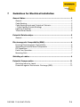
Table of Contents
About this Manual
Documentation Concept ............................................................................... 2-2
General Information ...................................................................................... 2-3
Prescribed Use ........................................................................................ 2-3
Notes Concerning Planning /Installation of this Product ........................ 2-3
Description of Symbols Used ....................................................................... 2-4
1
BL67 Philosophy
The Basic Concept........................................................................................ 1-2
Flexibility.................................................................................................. 1-2
Convenient Handling ............................................................................... 1-3
BL67 Components ........................................................................................ 1-4
Gateways................................................................................................. 1-4
Electronic Modules.................................................................................. 1-5
Base Modules.......................................................................................... 1-6
End Plate ................................................................................................ 1-7
2
Ethernet
System Description ...................................................................................... 2-2
Ethernet MAC-ID ..................................................................................... 2-2
IP address ............................................................................................... 2-2
Network Classes ..................................................................................... 2-3
Data transfer............................................................................................ 2-4
Checking the communication via "ping-signals" .................................... 2-6
ARP (Address Resolution Protocol)......................................................... 2-6
Transmission Media ................................................................................ 2-7
3
Technical Features
General.......................................................................................................... 3-2
Function ........................................................................................................ 3-3
Programming........................................................................................... 3-3
Technical Data ............................................................................................. 3-4
Structure of PLC runtime system ............................................................ 3-5
Connection possibilities .............................................................................. 3-10
Field bus connection ............................................................................. 3-10
Power Supply via 7/8" connector.......................................................... 3-11
Connection PS2 female connector ....................................................... 3-12
D301033 1106 BL67-PG-EN
i
Table of Contents
Address Setting........................................................................................... 3-15
LED-behavior......................................................................................... 3-15
Default setting of the gateway............................................................... 3-16
Address setting via the rotary-mode ..................................................... 3-17
Address setting via BootP-mode .......................................................... 3-18
Address setting via DHCP-mode .......................................................... 3-19
Address setting via PGM-mode ............................................................ 3-20
Addressing via PGM-DHCP .................................................................. 3-21
Address setting via the software "I/O-ASSISTANT" ............................. 3-22
SET Button .................................................................................................. 3-24
Status Indicators/Diagnostic Messages Gateway ...................................... 3-25
Diagnostic Messages via LEDs ............................................................. 3-25
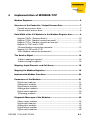
4
Implementation of MODBUS-TCP
Modbus Registers ......................................................................................... 4-3
Structure of the Packed In-/ Output Process Data ...................................... 4-7
Packed input-process data ..................................................................... 4-7
Packed output process data ................................................................... 4-8
Data Width of the I/O-Modules in the Modbus-Register Area...................... 4-9
Register 100Ch: "Gateway-Status"....................................................... 4-10
Register 1130h: "Modbus-connection-mode" ...................................... 4-12
Register 1131h: "Modbus-connection time-out" .................................. 4-12
Register 0×113C and 0×113D:
"Restore Modbus-connection parameter" ............................................ 4-12
Register 0×113E and 0×113F:
"Save Modbus-connection parameters"............................................... 4-13
The Service-Object ..................................................................................... 4-14
"Indirect reading of registers" ............................................................... 4-16
"Indirect writing of registers"................................................................. 4-16
Mapping: Input-Discrete- and Coil-Areas ................................................... 4-18
Mapping the Modbus Registers.................................................................. 4-19
Implemented Modbus Functions ................................................................ 4-20
Parameters of the Modules......................................................................... 4-21
Digital input modules............................................................................. 4-21
Analog input modules............................................................................ 4-23
Digital output modules .......................................................................... 4-27
Analog output modules ......................................................................... 4-28
Digital combi modules........................................................................... 4-30
Technology modules ............................................................................. 4-32
ii
D301033 1106 BL67-PG-EN
Diagnostic Messages of the Modules......................................................... 4-42
Power supply modules .......................................................................... 4-42
Digital input modules............................................................................. 4-42
Analog input modules............................................................................ 4-43
Digital output modules .......................................................................... 4-46
Digital combi modules........................................................................... 4-49
Technology modules ............................................................................. 4-51
5
Configuration of the programmable gateway with CoDeSys
General.......................................................................................................... 5-2
System requirements .............................................................................. 5-2
Installation of the BL67 target files................................................................ 5-3
Installation ............................................................................................... 5-4
BL67 Hardware Configuration ...................................................................... 5-6
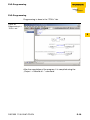
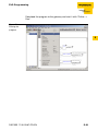
Configuration/ Programming of the PG in CoDeSys .................................... 5-7
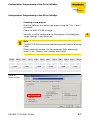
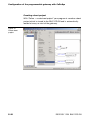
Creating a new project ............................................................................ 5-7
Configuration of the BL67 Station............................................................... 5-13
Parameterization of the I/O modules..................................................... 5-14
Addressing the in- and output data ...................................................... 5-14
Mapping of the Modbus Registers........................................................ 5-17
PLC-Programming ...................................................................................... 5-19
Online .................................................................................................... 5-20
Creating a boot project ......................................................................... 5-22
6
Guidelines for Station Planning
Module Arrangement .................................................................................... 6-2
Random Module Arrangement ................................................................ 6-2
Complete Planning........................................................................................ 6-3
Maximum System Extension......................................................................... 6-4
Creating Potential Groups ....................................................................... 6-5
Plugging and Pulling Electronic Modules ..................................................... 6-6
Extending an Existing Station ....................................................................... 6-7
7
Guidelines for Electrical Installation
General Notes ............................................................................................... 7-2
General .................................................................................................... 7-2
Cable Routing.......................................................................................... 7-2
Cable Routing Inside and Outside of Cabinets: ...................................... 7-2
D301033 1106 BL67-PG-EN
iii
Table of Contents
Lightning Protection ................................................................................ 7-3
Transmission Media ................................................................................ 7-4
Potential Relationships ................................................................................. 7-5
General .................................................................................................... 7-5
Electromagnetic Compatibility (EMC) ........................................................... 7-6
Ensuring Electromagnetic Compatibility ................................................. 7-6
Grounding of Inactive Metal Components .............................................. 7-6
PE Connection......................................................................................... 7-7
Earth-Free Operation............................................................................... 7-7
Mounting Rails......................................................................................... 7-7
Shielding of cables........................................................................................ 7-9
Potential Compensation.............................................................................. 7-11
Switching Inductive Loads .................................................................... 7-11
Protection against Electrostatic Discharge (ESD) ................................. 7-12
8
Appendix
Network Configuration .................................................................................. 8-2
Changing the IP address of a PC/ network interface card...................... 8-3
Deactivating/ adapting the firewall in Windows XP................................. 8-9
Nominal Current Consumption of Modules at Ethernet ............................. 8-12
9
Glossary
10
Index
iv
D301033 1106 BL67-PG-EN
About this Manual
Documentation Concept .................................................................... 2
General Information........................................................................... 3
Prescribed Use ............................................................................................3
Notes Concerning Planning /Installation of this Product ............................3
Description of Symbols Used............................................................. 4
D301033 1106 BL67-PG-EN
0-1
About this Manual
Documentation Concept
This manual contains information about the programmable BL67
MODBUS-TCP gateway BL67-PG-EN.
The following chapters contain a short BL67 system description, a
description of the field bus system Ethernet, exact information about
function and structure of the BL67 Ethernet gateways as well as all
bus specific information concerning the connection to automation
devices, the maximum system extension etc.
The bus-independent I/O-modules for BL67 as well as all further
fieldbus-independent chapters like mounting, labelling etc. are
described in a separate manual.
BL67 I/O-modules
(TURCK-Documentation-No.: German D300572/
English D300529)
Furthermore, the manual mentioned above contains a short description of the project planning and diagnostics software for TURCK
I/O-systems, the engineering software I/O-ASSISTANT.
0-2
D301033 1106 BL67-PG-EN
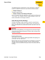
General Information
General Information
Attention
Please read this section carefully. Safety aspects cannot be left to
chance when dealing with electrical equipment.
This manual contains all necessary information about the prescibed
use of the programmable TURCK gateway BL67-PG-EN.
It has been specially conceived for personnel with the necessary
qualifications.
Prescribed Use
Warning
The devices described in this manual must be used only in applications prescribed in this manual or in the respective technical descriptions, and only with certified components and devices from
third party manufacturers.
Appropriate transport, storage, deployment and mounting as well as
careful operating and thorough maintenance guarantee the troublefree and safe operation of these devices.
Notes Concerning Planning /Installation of this Product
Warning
All respective safety measures and accident protection guidelines
must be considered carefully and without exception.
D301033 1106 BL67-PG-EN
0-3
About this Manual
Description of Symbols Used
Warning
This sign can be found next to all notes that indicate a source of hazards. This can refer to danger to personnel or damage to the system
(hardware and software) and to the facility.
This sign means for the operator: work with extreme caution.
Attention
This sign can be found next to all notes that indicate a potential
hazard.
This can refer to possible danger to personnel and damages to the
system (hardware and software) and to the facility.
Note
This sign can be found next to all general notes that supply important information about one or more operating steps. These specific
notes are intended to make operation easier and avoid unnecessary
work due to incorrect operation.
0-4
D301033 1106 BL67-PG-EN
1
BL67 Philosophy
The Basic Concept ............................................................................ 2
Flexibility......................................................................................................2
Convenient Handling ...................................................................................3
BL67 Components ............................................................................. 4
Gateways.....................................................................................................4
Electronic Modules......................................................................................5
– Power Feeding Modules ..........................................................................5
Base Modules..............................................................................................6
End Plate ....................................................................................................7
D301033 1106 BL67-PG-EN
1-1
BL67 Philosophy
The Basic Concept
BL67 is a modular IP67 I/O-system for use in industrial automation.
It connects the sensors and actuators in the field to the higher-level
master.
BL67 offers modules for practically all applications:
Digital input and output modules
Analog input and output modules
Technology modules (RS232 interface,...)
A complete BL67 station counts as one station on the bus and
therefore occupies one fieldbus address in any given fieldbus structure. A BL67 station consists of a gateway, power distribution
modules and I/O-modules.
The connection to the relevant fieldbus is made via the bus-specific
gateway, which is responsible for the communication between the
BL67 station and the other fieldbus stations.
The communication within the BL67 station between the gateway
and the individual BL67 modules is realized via an internal module
bus.
Note
The gateway is the only fieldbus-dependent module on a BL67 station. All other BL67 modules are not dependent on the fieldbus
used.
Flexibility
A BL67 station can contain modules in any combination, which
means it is possible to adapt the system to practically all applications in automated industries.
1-2
D301033 1106 BL67-PG-EN
The Basic Concept
Convenient Handling
1
All BL67 modules, with the exception of the gateway, consist of a
base module and an electronic module.
The gateway and the base modules are either snapped onto a
mounting rail or are directly mounted onto the machine frame. The
electronic modules are plugged onto the appropriate base modules.
After disconnection of the load, the electronic modules can be
plugged or pulled when the station is being commissioned or for
maintenance purposes, without having to disconnect the field wiring
from the base modules.
D301033 1106 BL67-PG-EN
1-3
BL67 Philosophy
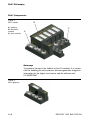
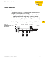
BL67 Components
Figure 1:
BL67 station
A gateway
B electronic
module
C base module
B
C
A
Gateways
The gateway connects the fieldbus to the I/O-modules. It is responsible for handling the entire process data and generates diagnostic
information for the higher-level master and the software tool
I/O-ASSISTANT.
Figure 2:
BL67 gateway
1-4
D301033 1106 BL67-PG-EN
BL67 Components
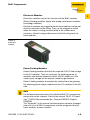
Electronic Modules
1
Electronic modules contain the functions of the BL67 modules
(Power Feeding modules, digital and analog input/output modules,
technology modules).
Electronic modules are plugged onto the base modules and are not
directly connected to the wiring. They can be plugged or pulled
when the station is being commissioned or for maintenance
purposes, without having to disconnect the field wiring from the
base modules.
Figure 3:
electronic
module
Power Feeding Modules
Power Feeding modules distribute the required 24 V DC field voltage
to the I/O-modules. They are necessary for building groups of
modules with different potentials within a BL67 station, or if the
rated supply voltage for the outputs cannot be guaranteed.
Power Feeding modules are potentially isolated from the gateway,
the adjoining power supply module and the I/O-modules to the left
side.
Note
For detailed information about the individual BL67 I/O components,
please refer to the chapters 2 to 8 of the manual "BL67- I/O-modules" (TURCK Documentation-No.: German D300572; English:
D300529).
The "Appendix" to the manual mentioned above contains (amongst
others) a list of all BL67 components and the assignment of electronic modules to base modules.
D301033 1106 BL67-PG-EN
1-5
BL67 Philosophy
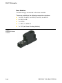
Base Modules
The field wiring is connected to the base modules.
These are available in the following connection variations:
1 x M12, 2 x M12, 2 x M12-P, 4 x M12, 4 x M12-P
4 x M8, 8 x M8
1 x M12-8
1 × M23, 1 x M23-19
1 x 7/8" (for Power Feeding Module)
Figure 4:
example of a base
module
1-6
D301033 1106 BL67-PG-EN
BL67 Components
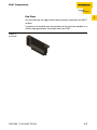
End Plate
1
An end plate on the right-hand side physically completes the BL67
station.
It protects the module bus connections of the last base module in a
station and guarantees the protection class IP67.
Figure 5:
end plate
D301033 1106 BL67-PG-EN
1-7
BL67 Philosophy
1-8
D301033 1106 BL67-PG-EN
2
Ethernet
System Description ........................................................................... 2
Ethernet MAC-ID .........................................................................................2
IP address ...................................................................................................2
Network Classes .........................................................................................3
Data transfer................................................................................................4
– IP (Internet Protocol) ................................................................................5
– TCP (Transmission Control Protocol) ......................................................5
– Modbus TCP ............................................................................................5
Checking the communication via "ping-signals" ........................................6
ARP (Address Resolution Protocol).............................................................6
Transmission Media ....................................................................................7
D301033 1106 BL67-PG-EN
2-1
Ethernet
System Description
Originally developed by DEC, Intel and Xerox (as DIX standard) for
data transmission between office equipment, Ethernet stands for
the IEEE 802.3 CSMA/CD specification published in 1985.
The rapid increase of application and the worldwide use of this technology enables problem-free and above all cost-effective connection to existing networks.
Ethernet MAC-ID
The Ethernet MAC-ID is a 6-byte-value which serves to definitely
identify an Ethernet device. The MAC-ID is determined for each
device by the IEEE (Institute of Electrical and Electronics Engineers,
New York).
The first 3 bytes of the MAC-ID contain a manufacturer identifier
(TURCK: 00:07:46:xx:xx:xx). The last 3 bytes can be chosen freely
by the manufacturer for each device and contain a definite serial
number.
A label on the TURCK modules shows the respective MAC-ID.
In addition to that, the MAC-ID can be read out using the software
tool "I/O-ASSISTANT".
IP address
Each Ethernet-host receives its own IP address. In addition to that
the node knows its netmask and the IP address of the default
gateway.
The IP address is a 4-byte-value which contains the address of the
network to which the node is connected as well as the host address
in the network.
The IP address of the gateway BL67-PG-EN is predefined as
follows:
2-2
IP address:
192.168.1.254
netmask:
255.255.255.0
gateway:
192.168.1.1
D301033 1106 BL67-PG-EN
System Description
The netmask shows which part of the IP address defines the
network as well as the network class and which part of the IP
address defines the single node in the network.
2
In the example mentioned above, the first 3 bytes of the IP address
define the network. They contain the subnet-ID 192.168.1.
The last byte of the IP address defines the node’s address within the
network.
Note
In order to build up the communication between a PC and an
Ethernet-module, both have to be nodes of the same network.
If necessary, the nodes’ network addresses have to be adapted one
to another. Please read Chapter 8, „Changing the IP address of a
PC/ network interface card”, page 8-3.
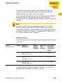
Network Classes
The available networks are divided into the different network classes
A, B, and C.
Figure 6:
Network classes
Class
Network
addresses
A
Bytes
for net
address
Bytes for
host
address
No. of the
possible
networks/
hosts
1.×××.×××.×××1
126.×××.×××.×××
3
126/ 224
B
128.0.×××.××× 191.255.×××.×××
2
2
214/ 216
C
192.0.0.××× 223.255.255.×××
3
1
221/ 256
According to their predefined address 192.168.1.××× the BL67
gateways are thus nodes of a Class C network.
D301033 1106 BL67-PG-EN
2-3
Ethernet
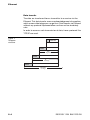
Data transfer
The data are transferred from a transmitter to a receiver via the
Ethernet. This data transfer uses no acknowledgement of reception,
which means data telegrams can get lost. Data transfer via Ethernet
without any protocol implementation can thus not be absolutely
safe.
In order to assure a safe transmission of data, frame-protocols like
TCP/IP are used.
Figure 7:
Telegram
structure
LAYER 7
Modbus etc.
TCPHeader
TCP-DATA
TCPSegment
IPHeader
IP-DATA
IPPackage
EthernetHeader
EtherNet-DATA
EtherNetPackage
2-4
D301033 1106 BL67-PG-EN
System Description
IP (Internet Protocol)
The Internet Protocol is a connection-free transport protocol. The
protocol does not use acknowledgement messages, telegrams can
get lost. It is thus not suitable for safe data transfer. The main functions of the internet protocol are the addressing of hosts and the
fragmentation of data packages.
TCP (Transmission Control Protocol)
The Transmission Control Protocol (TCP) is a connection-oriented
transport protocol and is based on the Internet Protocol. A safe and
error-free data transport can be guaranteed by means of certain
error diagnostic mechanisms as for example acknowledgement and
time monitoring of telegrams.
MODBUS-TCP
In Ethernet TCP/IP networks, MODBUS-TCP uses the Transport
Control Protocol (TCP) for the transmission of the Modbus application protocol.
All parameters and data are embedded in the user data of the TCPtelegram using the encapsulation protocol: the client generates a
special header (MBAP = Modbus Application Header), which
enables the server to clearly interpret the received Modbus-parameters and -commands.
The Modbus protocol is thus part of the TCP/IP-protocol.
The communication via Modbus is realized by means of function
codes embedded in the data telegram.
Figure 8:
telegram structure
MODBUS-TCP
The function codes contain, amongst others, commands for reading
input data or writing output data. Please read Chapter 4, „Implemented Modbus Functions”, page 4-17 for further information about
the function codes implemented in the BL67 gateway.
D301033 1106 BL67-PG-EN
2-5
2
Ethernet
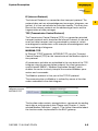
Checking the communication via "ping-signals"
You can check the communication between nodes in a network
using ping-signals in the DOS-prompt of your PC.
For that purpose, please enter the command "ping" and the IP
address of the network node to be checked.
If the node answers the ping-signal, it is ready for communication
and takes part in the data transfer.
Figure 9:
ping-signal
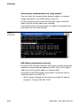
ARP (Address Resolution Protocol)
In each TCP/IP-capable computer, ARP serves to clearly assign the
worldwide unique hardware addresses (MAC-IDs) to the single IP
addresses of the network nodes via internal tables.
Using ARP in the DOS-prompt, every node in a network can be
clearly identified via its MAC-ID.
Write a ping command for the respective station/ IP address:
(example: "x:\\ping 192.168.1.100").
2-6
D301033 1106 BL67-PG-EN
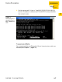
System Description
Via the command "x:\\arp -a" the MAC-ID (00-07-46-ff-60-13)
for this IP address is determined. This MAC-ID clearly identifies
the network node.
Figure 10:
Determination of
the MAC-ID of a
BL67 module via
ARP
Transmission Media
For a communication via Ethernet, different transmission media can
be used (see Chapter 7, page 7-4).
D301033 1106 BL67-PG-EN
2-7
2
Ethernet
2-8
D301033 1106 BL67-PG-EN
3
Technical Features
General .............................................................................................. 2
Function............................................................................................. 3
Programming...............................................................................................3
Technical Data .................................................................................. 4
Gateway structure .......................................................................................5
Connection possibilities .................................................................. 10
Field bus connection .................................................................................10
– Ethernet-connection ..............................................................................10
Power Supply via 7/8" connector..............................................................11
Connection PS2 female connector ...........................................................12
– Connection with I/O-ASSISTANT-Connection Cable ............................12
– Connection Using Commercially Available Cables ...............................13
Address Setting ............................................................................... 15
LED-behavior.............................................................................................15
Default setting of the gateway...................................................................16
Address setting via the rotary-mode .........................................................17
Address setting via BootP-mode ..............................................................18
Address setting via DHCP-mode ..............................................................19
Address setting via PGM-mode ................................................................21
Addressing via PGM-DHCP ......................................................................22
Address setting via the software "I/O-ASSISTANT" .................................23
SET Button....................................................................................... 25
Status Indicators/Diagnostic Messages Gateway............................ 26
Diagnostic Messages via LEDs .................................................................26
D301033 1106 BL67-PG-EN
3-1
Technical Features
General
This chapter contains the general technical description of the
programmable BL67 gateway for Modbus TCP.
3-2
D301033 1106 BL67-PG-EN
Function
Function
The programmable BL67 gateways can be used as an autonomous
PLC or as a de-central PLC in a network interconnection for fast
signal processing
Hinweis
The programmable BL67 gateway BL67-PG-EN is designed as a
Single Task System.
The gateway handles the entire process data traffic between the
I/O-level and the PLC runtime system.
Programming
The gateways BL67-PG-××× are programmable according to
IEC61131-3 using the software tool CoDeSys V2.3 from 3S - Smart
Software Solutions GmbH.
For programming the gateway, the following programming
languages according the standards can be used:
LD
= Ladder
FDB
= Function Block Diagram
IL
= Instruction List
ST
= Structured Text
SFC
= Sequential Function Chart
D301033 1106 BL67-PG-EN
3-3
3
Technical Features
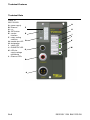
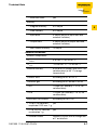
Technical Data
Figure 11:
BL67-PG-EN
G
A
B
C
D
E
F
G
H
I
J
K
L
power supply
Ethernet
n.c.
SET-button
serviceinterface
rotary coding
switches
module bus LED
designation
status LED
RUN/STOP LED
LEDs for
supply voltage
monitoring
Ethernet LEDs
F
H
E
I
J
D
K
M
C
B
A
3-4
D301033 1106 BL67-PG-EN
Technical Data
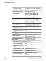
Structure of PLC runtime system
The BL67-PG-EN has the following structure:
Figure 12:
Structure of PLC
runtime system
3
BL67Systembus
service
interface
mC
memory
PS/2
Ethernet
interface
2
1
4
communication
bus
module bus
interface
3
Ethernet
5
1
2
3
4
V0
5 VDC
Vi
24 VDC
Power
bus
short circuit
protection
Vsens
PE
GND
Table 1:
Technical data
Ethernet gateway
Supply voltage
System supply VI (UB)
permissible range
Field supply VO (UL)
permissible range
Isys
D301033 1106 BL67-PG-EN
24 VDC
18 to 30 VDC
used to generate
the galvanically
isolated module
bus supply
24 VDC
18 to 30 VDC
600 mA
current consumption CPU + module
bus at maximum
system extension
3-5
Technical Features
IMB
max. 1,3 A
maximum output
current of module
bus supply
IVI
max. 4 A
short-circuit and
overload protection of the sensor
supply from
gateway or power
feeding module
Isolation voltages
URS
(Ethernet/
service interface)
500 V AC
UEN
(Ethernet/ module bus)
500 V DC
Usys
(VO/VI to Usys)
1000 V DC
SPS-data
Programming
– Software
– Released for
CoDeSys V 2.3
V 2.3.5.8
– Programming
languages
IEC 61131-3
(IL, LD, FDB, SFC, ST)
– Application tasks
1
– No. of POUs (Program 1024
Organization Unit)
– Programming interfaces
Processor
– Cycle time
3-6
RS232-interface, Ethernet
RISC, 32 bit
< 1 ms for 1000 IL-commands
(without I/O-cycle)
D301033 1106 BL67-PG-EN
Technical Data
– Real time clock
yes
Memory
– Program memory
512 KByte
– Data memory
512 KByte
– Input data
4 KByte (physical input data and
network variables)
– Output data
4 KByte (physical output data and
network variables)
– Non-volatile memory
16 KByte
3
Ambient conditions
Ambient temperature
– tAmbient
0 to +55 °C /32 to 131 °F
– tStore
- 25 to +85 °C / - 13 to 185 °F
Relative humidity
5 up to 95 % (inside), level RH-2, no
condensation (at 45 °C storage
temperature)
Climatic tests
according to IEC 61131-2
Corrosive gas
according to IEC 60068-2-42/43
– SO2
10 ppm (rel. humidity < 75 %, no
condensation)
– H2S
1.0 ppm (rel. humidity < 75 %, no
condensation)
Resistance to vibration
according to EN 61131
– 10 to 57 Hz,constant
yes
amplitude 0.075 mm, 1 g
– 57 to 150 Hz, constant
acceleration 1 g
yes
– Vibration mode
frequency cycles with a change rate
of 1 octave/min
D301033 1106 BL67-PG-EN
3-7
Technical Features
– Vibration duration
20 frequency cycles per coordinate
axis
Application conditions
according to EN 61131
Shock resistant
according to IEC 68-2-27, 18
shocks, semi-sinusoidal 15 g
threshold/11 ms, each in ± direction
per space coordinate
Repetitive shock resistance
according to IEC 68-2-29, 1000
shocks, semi-sinusoidal 25 g
threshold/6 ms, each in ± direction
per space coordinate
Drop and topple
according to IEC 68-2-31 and free
fall according to IEC 68-2-32
– Drop height (weight <
10 kg)
1m
– Drop height (weight 10 to 0.5 m
40 kg)
– Test cycles
7
Protection class
IP67
according to IEC 60529
Electromagnetic capability (EMC)
according to EN 61131-2/
EN 50082-2 (Industrial)
Static electricity according to EN 61000-4-2
Air discharge (direct)
8 kV
Relay discharge (indirect)
4 kV
Electromagnetic HF fields according to IEC 61131-2
3-8
Fast transients (Burst)
according to IEC 61131-2
Conducted interferences
induced by HF fields
according to IEC 61000-4-6
10 V
Criteria A
D301033 1106 BL67-PG-EN
Technical Data
A I/O-line-length
≤ 30 m
High energy
transients (Surge) A
voltage supply
according to IEC 61000-4-5
0,5 kV CM, 12 Ω/ 9 µF
0,5 kV DM, 2 Ω/ 18 µF
Criteria B
3
Reliability
Operational life MTBF
min. 120 000 h
Electronics modules pull/
plug cycles
20
Housing material
PC-V0 (Lexan)
Dimensions
Width x length x height
(mm/inch)
64,5 x 145,0 x 77,5 /
2,54 x 5,71 x 3,05
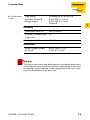
Warning
This device can cause radio disturbances in residential areas and in
small industrial areas (residential, business and trading). In this case,
the operator can be required to take appropriate measures to suppress the disturbance at his own cost.
D301033 1106 BL67-PG-EN
3-9
Technical Features
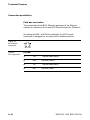
Connection possibilities
Field bus connection
The connection of the BL67 Ethernet gateways to the Ethernet
network is realized via the 4-pole M12 female connector “Ethernet“.
According to PNO- and ODVA-standards, the M12 female
connector is designed as a 4-pole and D-coded connector.
Figure 13:
M12-female
connector
Table 2:
Pin assignment
3-10
2
1
4
3
Pin-No.
1
TD+
Transmission Data +
2
RD+
Receive Data +
3
TD-
Transmission Data -
4
RD-
Receive Data -
D301033 1106 BL67-PG-EN
Connection possibilities
Power Supply via 7/8" connector
The power supply is realized via a 7/8" male connector on the
gateway.
3
Abbildung 14:
power supply via
1
7/8" male connec2
tor
5
4
3
Table 3:
PinPin assignment of No.
the 7/8" power
supply connector 1
Color
7/8"
black
GND
2
blue
GND
3
green/
yellow
PE
Protective earth
4
brown
VI (UB)
Feed-in of nominal voltage for input
modules (sensor supply); also used for
the generation of the system supply
voltage
5
white
VO (UL) Feed-in of nominal voltage for output
modules (can be switched off separately)
D301033 1106 BL67-PG-EN
Description
3-11
Technical Features
Connection PS2 female connector
The PS/2 female connector is used for the gateway’s connection to
the I/O-ASSISTANT (project planning and diagnostic software).
The interface is conceived as a 6-pole mini DIN connector.
In order to connect the gateway to the PC, two types of cables can
be used:
special I/O-ASSISTANT-connection cable from TURCK
(IOASSISTANT-ADAPTERKABEL-BL20/BL67; Ident-no.:
6827133)
Commercially available PS/2 cable with adapter cable
SUB-D/ PS/2
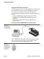
Connection with I/O-ASSISTANT-Connection Cable
Figure 15:
BL67-gateway
connected to PC
via special cable
B
C
A
The I/O-ASSISTANT-cables have a PS/2 male connector (connection for female connector on gateway) and a SUB-D female
connector (connection for male connector on PC).
Figure 16:
PS/2 male connector on the
connection cable
to the gateway
(top view)
4 3
5
2
6
3-12
1
D301033 1106 BL67-PG-EN
Connection possibilities
Figure 17:
9-pole SUB-D
female connector
on the cable for
connecting to PC
(top view)
5
4
9
3
8
2
7
1
3
6
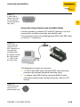
Connection Using Commercially Available Cables
A further possibility to connect PC and BL67 gateway is to use a
commercially available connection and adapter cable.
The connection shown in the following figure (PS2-male/ PS2-male)
is a 6-wire 1:1 connection.
Figure 18:
Connection between PC and
BL67 gateway via
commercially
available cable
B
C
A SUB-D- female
B PS/2-female
<–> PS/2-male
C PS/2-male
A
The following two cables are necessary:
1 x PS/2 cable (PS/2 male connector/PS/2 male connector)
(commercially available keyboard extension cable)
1 x adapter cable (PS/2 female connector/SUB-D female
connector) (commercially available extension cable for a PC
mouse)
Figure 19:
PS/2 female connector on the
2
gateway (top view)
3 4
5
1
6
D301033 1106 BL67-PG-EN
3-13
Technical Features
Figure 20:
9-pole SUB-D
male connector
on PC (top view)
1
2
6
3
7
4
8
5
9
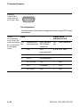
Pin assignment
The table below shows the pin assignment when using a PS/2 cable
and adapter:
Table 4:
PS/2
Pin assignment
when using PS/2
cable and adapter PinStandard PS/2
A not supported
by all adapter
cables.
3-14
9-pole serial
interface on PC
No.
BL67 gateway:
male connector PS/2 female
connector
PinNo.
Male connector
1
CLK
+5 V
(from gateway)
4, 6 A DTR, DSR
2
GND
GND
5
GND
3
DATA
not connected
–
–
4
n.c. (DATA2)
TxD
2
RxD
5
+5 V
/CtrlMode
7
RTS
6
n.c. (CLK2)
RxD
3
TxD
D301033 1106 BL67-PG-EN
Address Setting
Address Setting
The addressing of BL67-PG-EN can be realized via different modes:
rotary mode (manual addressing via rotary coding-switches)
3
PGM mode (manual addressing via software)
BootP mode, DHCP mode (automatic addressing via BootP/
DHCP-server at the boot-up of the gateway).
The setting of the address modes is done via the 3 rotary codingswitches at the gateway.
Note
It is not necessary to address the station’s internal module bus.
Attention
The cover of the decimal rotary coding-switches must be closed by
tightening the screw after use.
The seal in the cover must not be damaged or slipped.
The protection class IP67 can only be guaranteed when the cover is
closed correctly.
LED-behavior
During it’s start-up, the module waits for the address setting via the
BootP-server. This is indicated by the red flashing "MS" LED. The
LED begins to flash green, as soon as the address setting via the
server is completed. The station is ready for communication.
D301033 1106 BL67-PG-EN
3-15
Technical Features
Default setting of the gateway
The gateway’s "out of the box"-settings are the following:
IP address
subnet mask
default gateway
192.168.1.254
255.255.255.000
192.168.1.1
Note
The gateway can be reset to these default settings by the user at any
time.
To reset the gateway, please set the three coding-switches at the
gateway to "000" followed by a power-on reset.
Figure 21:
Decimal rotary
coding-switches
for the address
setting
9 0 1
2
8
3
7
x 100
6 5 4
9 0 1
2
8
3
7
x 10
6 5 4
9 0 1
2
8
3
7
x1
6 5 4
000: 192.168.1.254
1 - 254: static rotary
300: BootP
400: DHCP
500: PGM
600: PGM-DHCP
Attention
After every change of the address-mode, a voltage reset must be
carried out.
3-16
D301033 1106 BL67-PG-EN
Address Setting
Address setting via the rotary-mode
When using the rotary-mode, the last byte of the gateway’s IP
address can be set via the rotary coding-switches at the gateway.
3
Note
All other network settings are stored in the module’s non-volatile
EEPROM and can not be changed in the rotary-mode.
Addresses in the range from 0 to 254 can be allocated. The
addresses 0 and 255 are reserved for broadcast messages in the
subnet.
The following example shows the setting of the address 173.
Figure 22:
Address setting
9 0 1
2
8
3
7
× 100
6 5 4
9 0 1
2
8
3
7
× 10
6 5 4
9 0 1
2
8
3
7
×1
6 5 4
Attention
The settings carried out in the rotary-mode are not stored in the
module’s EEPROM. Thus, they will get lost in case of a subsequent
address-assignment via a BootP/ DHCP or PGM.
Attention
After changing the position of the rotary coding-switches, a voltage
reset must be carried out to store the new address.
D301033 1106 BL67-PG-EN
3-17
Technical Features
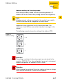
Address setting via BootP-mode
The address setting is carried out by a BootP-server in the network
after the start-up of the gateway.
In order to activate the BootP-mode, the rotary coding-switches
have to be set to "300".
Figure 23:
BootP-mode
9 0 1
8
2
7
3
× 100
6 5 4
9 0 1
2
8
3
7
× 10
6 5 4
9 0 1
2
8
3
7
×1
6 5 4
Note
The IP address as well as the default subnet mask assigned to the
gateway by the BootP-server are stored in the gateway’s non-volatile memory.
If the gateway is subsequently switched to rotary- or PGM-mode,
the settings carried out via BootP (IP address, subnet mask, etc) will
be taken from the module’s EEPROM.
3-18
D301033 1106 BL67-PG-EN
Address Setting
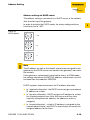
Address setting via DHCP-mode
The address setting is carried out by a DHCP-server in the network
after the start-up of the gateway.
In order to activate the DHCP-mode, the rotary coding-switches
have to be set to "400".
Figure 24:
DHCP-Modus
9 0 1
2
8
3
7
× 100
6 5 4
9 0 1
2
8
3
7
× 10
6 5 4
9 0 1
2
8
3
7
×1
6 5 4
Note
The IP address as well as the default subnet mask assigned to the
gateway by the DHCP-server are stored in the gateway’s non-volatile memory.
If the gateway is subsequently switched to rotary- or PGM-mode,
the settings carried out via DHCP (IP address, subnet mask, etc) will
be taken from the module’s EEPROM.
DHCP supports three mechanisms for IP address allocation:
In "automatic allocation", the DHCP-server assigns a permanent
IP address to a client.
In "dynamic allocation", DHCP assigns an IP address to a client
for a limited period of time. After this time or until the client
explicitly relinquishes the address, the address can be reassigned.
In "manual allocation", a client's IP address is assigned by the
network administrator, and DHCP is used simply to convey the
assigned address to the client.
D301033 1106 BL67-PG-EN
3-19
3
Technical Features
Address setting via PGM-mode
The PGM-mode enables the access of I/O-ASSISTANTs to the
module’s network settings.
In order to activate the PGM-mode, the rotary coding-switches have
to be set to "500".
Figure 25:
PGM-mode
9 0 1
2
8
3
7
× 100
6 5 4
9 0 1
2
8
3
7
× 10
6 5 4
9 0 1
2
8
3
7
×1
6 5 4
Note
In the PGM-mode, all network settings (IP address, subnet mask,
etc.) are read from the module’s internal EEPROM.
The settings carried out in the rotary-mode are stored in the
module’s non-volatile EEPROM.
3-20
D301033 1106 BL67-PG-EN
Address Setting
Addressing via PGM-DHCP
The addressing of the BL67 Modbus TCP gateway via PGM-DHCP
is at the moment comparable to the addressing via DHCP (see page
3-19).
3
D301033 1106 BL67-PG-EN
3-21
Technical Features
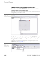
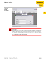
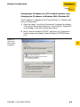
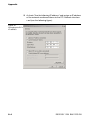
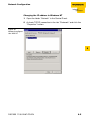
Address setting via the software "I/O-ASSISTANT"
The software-tool "I/O-ASSISTANT" enables direct access to the
Ethernet-network via the fieldbus cable.
Naturally, the access to the single station via the service interface at
the gateway is possible as well.
Figure 26:
Interface Ethernet
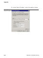
The IP address as well as the subnet mask of the TURCK Ethernet
gateways can be changed according to the application by using the
integrated Address Tool.
Changes in the network-configuration are only accepted in the
PGM-mode (see page 3-20).
Figure 27:
Opening the
Address-Tool
3-22
D301033 1106 BL67-PG-EN
Address Setting
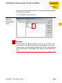
Figure 28:
change
IP address
3
Attention
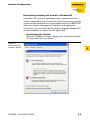
Please observe that, if the system integrated Windows-firewall is activated, difficulties may occur during the communication between
the gateway and the Address-tool. The firewall may possibly inhibit
the access of the tool on Ethernet.
D301033 1106 BL67-PG-EN
3-23
Technical Features
SET Button
The SET button on the gateway is used to save the Current Configuration of the station as the Reference Configuration in the
gateway’s non volatile configuration memory.
Note
Please press the SET button for 10 seconds after every change in
the station’s hardware configuration in order to save the Current
Configuration as the Reference Configuration in the Gateway.
3-24
D301033 1106 BL67-PG-EN
Status Indicators/Diagnostic Messages Gateway
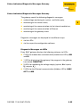
Status Indicators/Diagnostic Messages Gateway
The gateway sends the following diagnostic messages:
undervoltage monitoring for system- and field supply,
3
monitoring of the station status,
monitoring of the communication via the internal module bus,
monitoring of the communication to Ethernet
monitoring of the gateway status
Diagnostic messages are displayed in two different ways:
via the LEDs
via the respective configuration software
Diagnostic Messages via LEDs
Every BL67 gateway displays the following statuses via LEDs:
2 LEDs for module bus communication (module bus LEDs): GW
and IO
1 LED for displaying if the gateway/ the program in the gateway
has started: RUN/STOP
3 LEDs for monitoring the voltage supply (system, VCC/ inputs,
Vi/ outputs, Vo).
2 LEDs for the Ethernet communication (fieldbus-LEDs): LINK/
ACT and MS.
D301033 1106 BL67-PG-EN
3-25
Technical Features
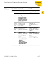
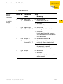
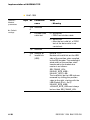
Table 5:
LED-displays
3-26
LED Status
Meaning
Remedy
GW
Off
CPU not supplied.
–
Green
Firmware active,
gateway ready to
operate and transmit
–
Green, Firmware not active.
flashing,
1 Hz
If LED "IO" red → Firmware download necessary
Green, Firmware active,
flashing, gateway hardware
4 Hz
defect.
Replace the gateway.
Red
– Check wiring at the
gateway and the voltage
supply.
– Dismount modules
– Replace the gateway.
Controller is not
ready, VCC level is
not within the
required range →
possible reasons:
– too many modules
connected to the
gateway
– short circuit in
connected module
– hardware error in
gateway
D301033 1106 BL67-PG-EN
Status Indicators/Diagnostic Messages Gateway
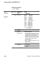
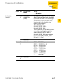
Table 5:
LED-displays
LED Status
Meaning
Remedy
IO
CPU not supplied.
– Check the voltage
supply at the gateway.
Off
Green
Module bus is
–
running,
the configured
module bus station
corresponds to the
physically connected
station, communication is active.
Green, Station is in the
flashing I/O-ASSISTANT
1 Hz
Force Mode.
– Deactivate the
I/O-ASSISTANT Force
Mode.
Green, Maximum number of – Check the number of
flashing modules at the
modules connected to
4 Hz
gateway is exceeded. the gateway, dismount
modules
Red
D301033 1106 BL67-PG-EN
Controller is not
– Check wiring at the
ready, VCC level is not
gateway and the voltage
supply.
within the required
– Dismount modules
range →
possible reasons:
– Replace the gateway.
– too many modules
connected to the
gateway
– short circuit in
connected module
– hardware error in
– gateway
3-27
3
Technical Features
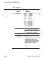
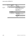
Table 5:
LED-displays
LED Status
IO
Meaning
Remedy
Red
Non-adaptable modi- – Compare the planned
flashing, fication of the physiBL67 station with the
1 Hz
cally connected
physical station.
– Check the physical
station.
station for defective or
incorrectly fitted electronics modules.
Red
no module bus
flashing, communication
4 Hz
Red/
green
flashing,
1 Hz
RUN/ Off
STOP
Green
– At least one module has
to be plugged and has to
be able to communicate
with the gateway.
Adaptable modifica- – Check the physical
tion of the physically
station for pulled or new
connected station;
but not planned
data transfer possible
modules.
No program loaded
into the gateway.
–
Application loaded to –
gateway, program
running.
Green
Application loaded to – Start the gateway/ the
flashing gateway, PLC not yet
PLC program.
started or stopped.
VCC
3-28
Red
PLC test during
gateway start.
–
Off
CPU not supplied
– Check the system
supply at the gateway.
Green
Module bus and CPU –
running
D301033 1106 BL67-PG-EN
Status Indicators/Diagnostic Messages Gateway
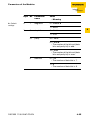
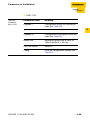
Table 5:
LED-displays
LED Status
Meaning
Remedy
VO
No voltage supply.
Check the system supply
at the gateway.
Off
Output
supply
ok.
– Check the wiring at Green
the gateway and the
voltage supply.
Green
Undervoltage VO,
flashing, system running
1 Hz
– Check the system
supply at the gateway
Green
Overvoltage VO,
flashing, system running
4 Hz
VI
Off
No voltage supply.
– Check the wiring of the
voltage supply at the
gateway
Green
sensor supply ok.
–
Green, undervoltage VI,
flashing, system running
1Hz
– Check the wiring of the
voltage supply at the
gateway
Green, Overvoltage VI,
flashing, system running
4 Hz
Red
D301033 1106 BL67-PG-EN
Short circuit or over- – Automatic restart when
load at sensor supply
debugging.
→ sensor supply is
switched off
3-29
3
Technical Features
Table 5:
LED-displays
LED Status
Meaning
Remedy
LINK/Off
ACT
No Ethernet link
– Check the Ethernetconnection
Link, 100 Mbit
–
Green
MS
Green
Ethernet Traffic,
flashing 100 Mbit
–
Yellow
–
Link, 10 Mbit
Yellow, Ethernet Traffic,
flashing 10 Mbit
–
Green
–
Displays the logical
connection to a
Master (1. Modbus
TCP- connection)
Green, Gateway is ready for
flashing operation
–
Red
–
Gateway indicates
error
Red,
DHCP/BootP search
flashing of settings
3-30
–
D301033 1106 BL67-PG-EN
4
Implementation of MODBUS-TCP
Modbus Registers .............................................................................. 3
Structure of the Packed In-/ Output Process Data ........................... 7
Packed input-process data .........................................................................7
Packed output process data .......................................................................8
Data Width of the I/O-Modules in the Modbus-Register Area ........... 9
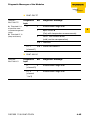
Register 100Ch: "Gateway-Status"...........................................................10
Register 1130h: "Modbus-connection-mode" ..........................................12
Register 1131h: "Modbus-connection time-out" ......................................12
Register 0×113C and 0×113D:
"Restore Modbus-connection parameter" ................................................12
Register 0×113E and 0×113F:
"Save Modbus-connection parameters"...................................................13
The Service-Object .......................................................................... 14
"Indirect reading of registers" ...................................................................16
"Indirect writing of registers".....................................................................16
Mapping: Input-Discrete- and Coil-Areas ........................................ 18
Mapping the Modbus Registers ....................................................... 19
Implemented Modbus Functions ..................................................... 20
Parameters of the Modules ............................................................. 21
Digital input modules.................................................................................21
Analog input modules................................................................................23
Digital output modules ..............................................................................27
Analog output modules .............................................................................28
Digital combi modules...............................................................................30
Technology modules .................................................................................32
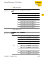
Diagnostic Messages of the Modules .............................................. 42
Power supply modules ..............................................................................42
Digital input modules.................................................................................42
Analog input modules................................................................................43
Digital output modules ..............................................................................46
Digital combi modules...............................................................................49
D301033 1106 BL67-PG-EN
4-1
Implementation of MODBUS-TCP
Technology modules .................................................................................51
4-2
D301033 1106 BL67-PG-EN
Modbus Registers
Modbus Registers
As soon as an application is downloaded to the BL67-PG-EN, the
programmable gateway simply allows read-only-access to the standard Modbus registers (0×0000h to 0×01FFh, 0×0800h to 0×09FFh).
A write-access is only possible using the Modbus output registers
(register 0×4400 to 0×47FF, see following table).
Note
If no application is loaded to the BL67-PG-EN, the programmable
gateway works as a standard-gateway for MODBUS-TCP.
Note
Some Modbus PLCs and/ or configuration tools do not define
register-number 0×0000h as the starting address according to the
Modbus specification. In this case, the address area may begin with
decimal "1".
D301033 1106 BL67-PG-EN
4-3
4
Implementation of MODBUS-TCP
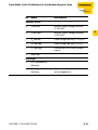
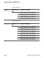
Table 6:
Modbus registers
of the gateway
A ro = read only
rw = read write
4-4
Address
(hex.)
Access
Description
0×0000 to
0×01FF
ro
packed process data of inputs
(process data length of modules, see
Table 7: "Data width of the I/O-modules")
0×0800 to
0×09FF
rw
packed process data of outputs
(process data length of modules, see
Table 7: "Data width of the I/O-modules")
0×1000 to
0×1006
ro
gateway identifier
0×100C
ro
gateway status (see Table 8: "Register
100Ch: gateway-status")
0×1010
ro
process image length in bit for the intelligent output modules
0×1011
ro
process image length in bit for the intelligent input modules
0×1012
ro
process image length in bit for the digital
output modules
0×1013
ro
process image length in bit for the digital
input modules
0×1017
ro
register-mapping revision (always 1, if
not, mapping is incompatible with this
description)
A
D301033 1106 BL67-PG-EN
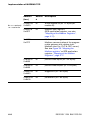
Modbus Registers
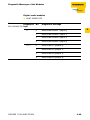
A ro = read only
rw = read write
Address
(hex.)
Access
0×1018 to
0×101A
ro
group diagnostics of I/O-modules 0 to 32
(1 bit per I/O-module)
0×1020
ro
watchdog, actual time [ms]
0×1120
rw
watchdog predefined time [ms]
(default: 0)
0×1121
rw
watchdog reset register
0×1130
rw
modbus connection mode register
0×1131
rw
modbus connection time-out in seconds
(default: 0 = never)
0×113C to
0×113D
rw
modbus parameter restore
0×113E to
0×113F
rw
modbus parameter save
0×2000 to
0×207F
rw
service-object, request-area
0×2080 to
0×20FF
ro
service-object, response-area
0×2400
ro
system voltage USYS [mV]
0×2401
ro
load voltage UL [mV]
0×2405
ro
load current IL [A]
0×27FE
ro
no. of entries in actual module list
0×27FF
rw
no. of entries in reference module list
0×2800 to
0×2840
rw
reference module list (32 × 4 bytes per
module-ID)
0×2900 to
0×29A0
ro
reserved
D301033 1106 BL67-PG-EN
Description
A
4
4-5
Implementation of MODBUS-TCP
A ro = read only
rw = read write
Address
(hex.)
Access
0×2A00 to
0×2A20
ro
actual module list (32 × 4 bytes per
module-ID)
0x4000 to
0x43FF
rw
Modbus input registers
(SPS application-registers, see also
"Mapping of the Modbus Registers",
page 5-17).
0x4400 to
0x47FF
4-6
Description
A
Modbus output registers
Modbus-communication of the programmable gateway with a higher-level
Modbus-client (i.e. PLC or OPC-server).
See also Figure 29: "Mapping the
Modbus registers" or SPS applicationregisters, "Mapping of the Modbus
Registers", page 5-17
0×8000 to
0×8400
ro
process data inputs (32 × 64 bytes)
0×9000 to
0×9400
rw
process data outputs (32 × 64 bytes)
0×A000 to
0×A400
ro
diagnostics (32 × 64 bytes)
0×B000 to
0×B400
rw
parameters (32 × 64 bytes)
D301033 1106 BL67-PG-EN
Structure of the Packed In-/ Output Process Data
Structure of the Packed In-/ Output Process Data
In order to assure a largely efficient access to the process data of a
station, the module data are consistently packed and mapped to a
coherent register area.
The I/O-modules are divided into digital and intelligent modules
(analog modules, serial interfaces).
4
Both module types are mapped in separate register ranges.
The data mapping always starts with the mapping of the intelligent
modules. Each module occupies as much Modbus registers as
necessary, depending on it’s data width. At least one register is
occupied. A RS232-module, for example, occupies 4 consecutive
registers (8 bytes) in the input and in the output area.
The data byte arrangement is done according to the physical order
in the station, from the left to the right.
The data of the intelligent modules are followed by the data of the
digital modules, also structured according to their physical appearance in the station. The Modbus registers for the digital data are
filled-up up to 16 bit. This means on the one hand that one Modbus
register can contain data of different digital modules and on the
other hand that the data of one digital module can be distributed
over multiple registers. Bit 0 of a digital module is thus not obligatory
located on a word limit.
Packed input-process data
input register area: 0000h to 01FFh
0000h
intelligent modules, digital input
input data
modules
01FFh
status/
diagnosis
free
Note
Independent of the I/O-configuration, an access to all 512 registers
is always possible. Registers that are not used send "0".
D301033 1106 BL67-PG-EN
4-7
Implementation of MODBUS-TCP
Status/ diagnosis
The area "status/diagnosis" comprises a maximum of 9 registers.
The first register contains a common gateway-/station-status.
The following registers (max. 8) contain a group diagnostic bit for
each I/O-module which shows whether a diagnostic message is
pending for the relevant module or not.
Status/ diagnosis
n + 0000h
gateway status
(Reg. 100Ch)
n + 0008h
group diagnosis I/O-modules 0...127
(registers 1018h to 101Fh)
Packed output process data
output register area: 0800h to 09FFh
0800h
intelligent modules,
output data
09FFh
digital output data
free
Note
Independent of the I/O-configuration, an access to all 512 registers
is always possible. Registers that are not used send "0" answering
a read access, write accesses are ignored.
4-8
D301033 1106 BL67-PG-EN
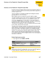
Data Width of the I/O-Modules in the Modbus-Register Area
Data Width of the I/O-Modules in the Modbus-Register Area
The following table shows the data width of the BL67 I/O-modules
within the modbus register area and the type of data alignment.
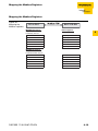
Table 7:
Data width of the
I/O-modules
Module
Process
input
Process
output
Alignment
BL67-4DI-x
4 bit
-
bit by bit
BL67-8DI-x
8 bit
-
bit by bit
BL67-4DO-x
-
4 bit
bit by bit
BL67-8DO-x
-
8 bit
bit by bit
BL67-16DO-x
-
16 bit
bit by bit
4
– digital inputs
– digital outputs
– analog inputs
BL67-2AI-x
2 words
word by word
– analog outputs
BL67-2AO-x
2 words
word by word
– technology modules
BL67-1RS×××
4 words
4 words
word by word
BL67-1SSI
4 words
4 words
word by word
BL67-1CVI
4 words
4 words
word by word
D301033 1106 BL67-PG-EN
4-9
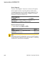
Implementation of MODBUS-TCP
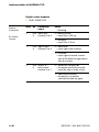
Register 100Ch: "Gateway-Status"
This register contains a general gateway-/ station-status.
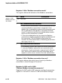
Table 8:
Register 100Ch:
gateway-status
Bit
Name
Description
Gateway
15
I/O Controller Error
The communication controller for
the I/O-system is faulty.
14
Force Mode Active
Error
The Force-Mode it activated.
The state of the outputs may no
longer accord to the settings made
via the fieldbus.
13
reserved
-
12
Modbus Wdog Error
A time-out in the Modbus communication occurred.
Module bus
4-10
11
I/O Cfg Modified Error
The I/O-configuration has been
changed and is now incompatible.
10
I/O Communication
Lost Error
No communication on the I/Omodule bus.
D301033 1106 BL67-PG-EN
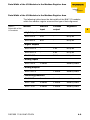
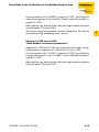
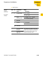
Data Width of the I/O-Modules in the Modbus-Register Area
Bit
Name
Description
Voltage errors
9
VI too low
System supply voltage too low
(< 18 VDC).
8
VI too high
System supply voltage too high
(> 30 VDC).
7
VO too low
Load voltage too low (< 18 VDC).
6
VO too high
Load voltage too high (> 30 V).
5
Isys too high
Overload of the system voltage
supply.
4
reserved
-
4
Warnings
3
I/O Cfg Modified
Warning
0
I/O Diags Active
Warning
D301033 1106 BL67-PG-EN
At least one I/O-module sends
active diagnostics.
4-11
Implementation of MODBUS-TCP
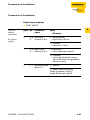
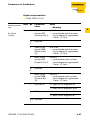
Register 1130h: "Modbus-connection-mode"
This register defines the behavior of the Modbus connections:
Table 9:
Bit
register 1130h:
Modbus-Connec- 15 to
tion-Mode
2
1
Name
Description
reserved
MB_ImmediateWritePermission
– 0: With the first write access, a write authorization for the
respective Modbus-connection is requested. If this
request fails, an exception response with exception-code
01h is generated. If the request is accepted, the write
access is executed and the write authorization remains
active until the connection is closed.
– 1:The write authorization for the respective Modbusconnection is already opened during the establishment of
the connection. The first Modbus-connection thus
receives the write authorization, all following connections
don’t (only if bit 0 = 1).
0
MB_OnlyOneWritePermission
– 0: all Modbus-connections receive the write authorization
– 1: only one Modbus-connection can receive the write
permission. A write permission is opened until a Disconnect. After the Disconnect the next connection which
requests a write access receives the write authorization.
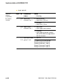
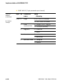
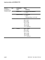
Register 1131h: "Modbus-connection time-out"
This register defines after which time of inactivity a Modbusconnection is closed through a Disconnect.
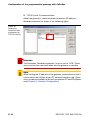
Register 0×113C and 0×113D:
"Restore Modbus-connection parameter"
Registers 0×113C and 0×113D serve for resetting the parameterregister 0×1120 and 0×1130 to 0×113B to the default settings.
4-12
D301033 1106 BL67-PG-EN
Data Width of the I/O-Modules in the Modbus-Register Area
For this purpose, write "0×6C6F" in register 0×113C. To activate the
reset of the registers, write "0×6164" ("load") within 30 seconds in
register 0×113D.
Both registers can also be written with one single request using the
function codes FC16 and FC23.
The service resets the parameters without saving them. This can be
achieved by using a following "save" service.
Register 0×113E and 0×113F:
"Save Modbus-connection parameters"
Registers 0×113E and 0×113F are used for the non-volatile saving
of parameters in registers 0×1120 and 0×1130 to 0×113B.
For this purpose, write "0×7361" in register 0×113E. To activate the
saving of the registers, write "0×7665" ("save") within 30 seconds in
register 0×113F.
Both registers can also be written with one single request using the
function codes FC16 and FC23.
D301033 1106 BL67-PG-EN
4-13
4
Implementation of MODBUS-TCP
The Service-Object
The service-object is used to execute one-time or acyclic services.
It is an acknowledge service which may serve, for example, to
parameterize an I/O-module.
2000h
2080h
20FFh
service request area
service response area
The service request area allows write access, the service response
area only read access.
Service request area
2000h
2001h 2002h 2003h 2004h
2005h 20FFh
service
no.
reserve service index/
d
code
addr
optional data
(0 to122 registers)
dataregcount
The register service no. in the request area can contain a user
defined value which is deleted after the execution of the service.
The register service code specifies which service is requested.
The register index/addr is optional and the meaning depends on
the particular service.
The register data-reg-count contains, depending on the service,
the number (0 to 122) of the transferred or of the requested data
registers.
Depending on the service, the optional data area can contain additional parameters and/or other data to be written.
Service response area
4-14
2080h
2081h 2082h 2083h 2084h
2085h 20FFh
service
no.
result
optional data
(0 to 122 registers)
service index/
code
addr
dataregcount
D301033 1106 BL67-PG-EN
The Service-Object
After the execution of a request, the registers service-no., service
code and index/addr in the response area contain a copy of the
values in the request area.
Note
The service no. is thus used for a simple handshake on the application level. The application increases the service no. with every request. The service is blocked, until the service number in the request
area matches the service number in the response area.
The register result shows whether the execution was successful or
not.
The register data-reg-count contains the number of data registers
(0 to 122).
The optional Data area can contain, depending on the service, the
requested data.
Supported service numbers::
Table 10:
Service code
Supported service
0×0000
numbers:
Meaning
no function
0×0003
indirect reading of registers
0×0010
indirect writing of registers
A service request may have the following results:
Table 11:
results of the
service request
Service code
Meaning
0×0000
error free execution of service
0×FFFE
service parameters
incorrect/ inconsistent
0×FFFF
service code unknown
D301033 1106 BL67-PG-EN
4-15
4
Implementation of MODBUS-TCP
Note
The services "indirect reading of registers" and "indirect writing of
registers " offer an additional possibility to access any Modbus
register.
Current Modbus-masters support only a limited number of registerareas that can be read or written during the communication with a
Modbus-server. These areas can not be changed during operation.
In this case, the services mentioned above enables non-cyclic access to registers.
"Indirect reading of registers"
1 to 122 (Count) Modbus-registers are read, starting with address
x (Addr).
service-request
2000h
2001h 2002h 2003h 2004h 2005h 207Fh
service
no.
0x0000 0x0003
Addr
Count
reserved
service-response
2080h
2081h 2082h 2083h 2084h 2085h 20FFh
service
no.
result
0x0003
Addr
Count
register contents
"Indirect writing of registers"
1 to 122 (Count) Modbus-registers are written, starting with address
x (Addr).
service-request
4-16
2000h
2001h 2002h 2003h 2004h 2005h 207Fh
service
no.
0x0000 0x0010
Addr
Count
register contents
D301033 1106 BL67-PG-EN
The Service-Object
service-response
2080h
2081h 2082h 2083h 2084h 2085h 20FFh
service
no.
result
0x0010
Addr
Count
reserved
4
D301033 1106 BL67-PG-EN
4-17
Implementation of MODBUS-TCP
Mapping: Input-Discrete- and Coil-Areas
Function codes FC1 ("Read Coils"), FC2 ("Read Discrete Inputs"),
FC 5 ("Write Single Coil") and FC15 ("Write Multiple Coils") allow
single-bit access to in- and output data.
The data mapping in these areas is the following:
Mapping: input-discrete-area
All digital inputs are stored in this area (offset "0").
Mapping: Coil-area
All digital outputs are stored in this area (offset "0").
Note
In addition to that, digital in- and outputs can also be accessed via
the packed process data, page 4-7 within the Modbus registers of
the gateway.
In the Modbus registers, the digital I/O data are stored with a variable offset, depending on the station’s I/O-configuration.
4-18
D301033 1106 BL67-PG-EN
Mapping the Modbus Registers
Mapping the Modbus Registers
Figure 29:
Mapping the
Modbus registers
PC or PLC
MODBUS registers
Inputs:
Read only access
BL67-PG-EN
BL67-registers
4
4000hex
Output register 0
4001hex
Output register 1
4002hex
Output register 2
4003hex
Output register 3
...
...
43FFhex
Output register 1023
MODBUS registers
Outputs:
Read and write access
4400hex
Input register 0
4401hex
Input register 1
4402hex
Input register 2
4403hex
Input register 3
...
...
47FFhex
Input register 1023
D301033 1106 BL67-PG-EN
4-19
Implementation of MODBUS-TCP
Implemented Modbus Functions
The BL67 gateway for Ethernet supports the following functions for
accessing process data, parameters, diagnostics and other
services.
Table 12:
Implemented
functions
Function Codes
No.
Function
Description
1
Read Coils
Serves for reading multiple output bits.
2
Read Discrete InputS
Serves for reading multiple input bits
3
Read Holding Registers
Serves for reading multiple output registers
4
Read Input Registers
Serves for reading multiple input registers
5
Write Single Coil
Serves for writing single output bits
6
Write Single Register
Serves for writing single output registers
15
Write Multiple Coils
Serves for writing multiple output bits
16
Write Multiple Registers
Serves for writing multiple output registers
23
Read/Write Multiple Registers
Serves for reading and writing multiple registers
4-20
D301033 1106 BL67-PG-EN
Parameters of the Modules
Parameters of the Modules
Digital input modules
BL67-4DI-PD
Table 13:
Module
parameters
Byte Bit
0
A Defaultsetting
Parameter
name
0 to input filter
3
channel 0 to 3
4
Value
– Meaning
0 = deactivate A:
– input filter: 0,25 ms.
1 = activate:
– input filter: 2,5 ms
1
0 to digital input
3
channel 0 to 3
0 = normal A:
– input signal not inverted.
1 = inverted:
– input signal inverted, conversion of the effective signal direction for sensors
2
0, 1 operation mode 0 = normal
group 1/ 2
1 = open circuit monitoring
Group A (channel 0 and 2)
Group B (channel 2 and 3).
D301033 1106 BL67-PG-EN
4-21
Implementation of MODBUS-TCP
BL67-8DI-PD
Table 14:
Module
parameters
Byte Bit
A Defaultsettings
0
Parameter
name
0 to input filter
7
channel 0 to 7
Value
– Meaning
0 = deactivate A:
– input filter: 0,25 ms.
1 = activate:
– input filter: 2,5 ms
1
0 to digital input
7
channel 0 to 7
0 = normal A:
– input signal not inverted.
1 = inverted:
– input signal inverted, conversion of the effective signal direction for sensors
2
4-22
0, 1, operation mode 0 = normal
2, 3 group 1 to 4
1 = open-circuit monitoring:
Group A (channel 0 and 4)
Group B (channel 1 and 5)
Group C (channel 3 and 6)
Group D (channel 4 and 7).
D301033 1106 BL67-PG-EN
Parameters of the Modules
Analog input modules
BL67-2AI-I (1 byte parameter per channel)
Table 15:
Module
parameters
Byte Bit
0/1
0
Parameter
name
Value
current mode
0 = 0...20 mA A
A Defaultsettings
– Meaning
4
1 = 4...20 mA
1
2
value
representation
0 = Integer (15 bit + sign) A
diagnosis
0 = activate A
1 = 12 bit (left justified)
1 = deactivate
3
channel
0 = activate A
1 = deactivate
BL67-2AI-V (1 byte parameter per channel)
Table 16:
Module
parameters
Byte Bit
0/1
0
Parameter
name
Value
voltage mode
0 = 0...10 V A
A Defaultsettings
– Meaning
1 = -10...+10 V
1
2
value
representation
0 = Integer (15 bit + sign) A
diagnosis
0 = activate A
1 = 12 bit (left justified)
1 = deactivate
3
channel
0 = activate A
1 = deactivate
D301033 1106 BL67-PG-EN
4-23
Implementation of MODBUS-TCP
BL67-2AI-PT (2 byte parameter per channel)
Table 17:
Module
parameters
Byte Bit
0/2
0
A Defaultsettings
1
2
Parameter
name
Value
mains
suppression
0 = 50 Hz A
value
representation
0 = Integer (15 bit + sign) A
diagnosis
0 = release A
– Meaning
0 = 60 Hz
1 = 12 bit (left justified)
1 = block
3
channel
0 = activate A
1 = deactivate
1/3
4-24
7 to element
4
0000 = PT100, -200...850 °CA
0001 = PT100, -200...150 °C
0010 = NI100, -60...250 °C
0011 = NI100, -60...150 °C
0100 = PT200, -200...850 °C
0101 = PT200, -200...150 °C
0110 = PT500, -200...850 °C
0111 = PT500, -200...150 °C
1000 = PT1000, -200...850 °C
1001 = PT1000, -200...150 °C
1010 = NI1000, -60...250 °C
1011 = NI1000, -60...150 °C
1100 = resistance, 0...100 Ω
1101 = resistance, 0...200 Ω
1110 = resistance, 0...400 Ω
1111 = resistance, 0...1000 Ω
0
0 = 2-wire A
measurement
mode
1 = 3-wire
D301033 1106 BL67-PG-EN
Parameters of the Modules
BL67-2AI-TC (2 byte parameter per channel)
Table 18:
Module
parameters
Byte Bit
0/1
0
A Defaultsettings
1
2
Parameter
name
Value
mains
suppression
0 = 50 Hz A
value
representation
0 = Integer (15 bit + sign) A
diagnosis
0 = release A
– Meaning
4
0 = 60 Hz
1 = 12 bit (left justified)
1 = block
3
channel
0 = activate A
1 = deactivate
7 to element
4
D301033 1106 BL67-PG-EN
0000 = type K, -270...1370 °CA
0001 = type B, +100...1820 °C
0010 = type E, -270...1000 °C
0011 = type J, -210...1200 °C
0100 = type N, -270...1300 °C
0101 = type R, -50...1760 °C
0110 = type S, -50...1540 °C
0111 = type T, -270...400 °C
1000 = ± 50 mV
1001 = ± 100 mV
1010 = ± 500 mV
1011 = ± 1000 mV
...
reserved
4-25
Implementation of MODBUS-TCP
BL67-4AI-V/I (1 byte parameter per channel)
Table 19:
Module
parameters
Byte Bit
0 to 3 0
Parameter
name
Value
range
0 = 0...10 V/ 0...20 mA A
A Defaultsettings
– Meaning
1 = -10...+10 V/ 4...20 mA
1
2
value
representation
0 = Integer (15 bit + sign) A
diagnosis
0 = release A
1 = 12 bit (left justified)
1 = block
3
channel
0 = activate A
1 = deactivate
4
operation mode 0 = voltage A
1 = current
4-26
D301033 1106 BL67-PG-EN
Parameters of the Modules
Digital output modules
BL67-16DO-0.1A-P
Tabelle 20:
Module parameters
Byte Bit
0
Value
– Meaning
0
Open circuit
0 to 12 A
current LSB
– current below which an open
(Channel 0 to 7)
circuit diagnosis is generated:
"Value" × 10 mA
1+
2
reserved
3
Open circuit
current MSB
(Channel 8 to
15)
4
Short-circuit
0 A to 12
current LSB
– current above which a short(Channel 0 to 7)
circuit diagnosis is generated:
"Value" × 10 mA.
5+
6
reserved
7
Short-circuit
current MSB
(Channel 8 to
15)
0 A to 12
– current above which a shortcircuit diagnosis is generated:
"Value" × 10 mA.
0
DiaOverCur
0 = short-circuit diagnosis off
A defaultsettings
1
Parameter
name
0 to 12 A
– current below which an open
circuit diagnosis is generated:
"Value" × 10 mA
1 = short-circuit diagnosis on A
1
DiaOpeLoa
0 = open circuit diagnosis off A
1 = open circuit diagnosis on
2 to reserved
7
D301033 1106 BL67-PG-EN
4-27
4
Implementation of MODBUS-TCP
Analog output modules
BL67-2AO-I
Table 21:
Module
parameters
Byte Bit
0
0
Parameter
name
Value
current mode
0 = 0...20 mA A
A Defaultsettings
– Meaning
1 = 4...20 mA
1
value
representation
2
reserved
3
channel
0 = Integer (15 bit + sign) A
1 = 12 bit (left justified)
0 = activate A
1 = deactivate
4 to reserved
7
1
2
4-28
substitute value The substitute value will be translow byte
mitted if the respective parameters
of the gateway have been set to
substitute value "output substitute value".
high byte
D301033 1106 BL67-PG-EN
Parameters of the Modules
BL67-2AO-V
Table 22:
Module
parameters
Byte Bit
0
0
Parameter
name
Value
voltage mode
0 = 0...10 V A
A Defaultsettings
– Meaning
4
1 = -10...+10 V
1
value
representation
2
reserved
3
channel
0 = Integer (15 bit + sign) A
1 = 12 bit (left justified)
0 = activate A
1 = deactivate
4 to reserved
7
1
2
D301033 1106 BL67-PG-EN
substitute value The substitute value will be translow byte
mitted if the respective parameters
of the gateway have been set to
substitute value "output substitute value".
high byte
4-29
Implementation of MODBUS-TCP
Digital combi modules
BL67-4DI4DO-PD
Table 23:
Module
parameters
Byte Bit
0
A Defaultsettings
Parameter
name
0 to input filter
3
channel 0 to 3
Value
– Meaning
0 = deactivate A:
– input filter: 0,25 ms.
1 = activate:
– input filter: 2,5 ms
1
0 to digital input
3
channel 0 to 3
0 = normal A:
– input signal not inverted.
1 = inverted:
– input signal inverted, conversion of the effective signal direction for sensors
2
0 to output at
overcurrent
3
channel 4 to 7
0 = automatic recovery A:
– the output switches-on automatically after a short-circuit
1 = controlled recovery:
– the output is manually
switched-off and on again.
4-30
D301033 1106 BL67-PG-EN
Parameters of the Modules
BL67-8XSG-PD
Table 24:
Module
parameters
Byte Bit
0
A Defaultsettings
Parameter
name
0 to input filter
7
channel 0 to 7
Value
– Meaning
0 = deactivate A:
– input filter: 0,25 ms.
4
1 = activate:
– input filter: 2,5 ms
1
0 to digital input
7
channel 0 to 7
0 = normal A:
– input signal not inverted.
1 = inverted:
– input signal inverted, conversion of the effective signal direction for sensors
2
0 to output at
7
overcurrent
channel 0 to 7
0 = automatic recovery A:
– the output switches-on automatically after a short-circuit
1 = controlled recovery:
– the output is manually
switched-off and on again.
3
0 to output
7
D301033 1106 BL67-PG-EN
0 = deactivate
1 = activate:
– selective activation of outputs
of the module
4-31
Implementation of MODBUS-TCP
Technology modules
BL67-1RS232
Table 25:
Module
parameters
Byte Bit
0
A Defaultsettings
Parameter
name
Value
– Meaning
3 to data rate
0
0000 =
300 bps
0001 =
600 bps
0010 = 1200 bps
0100 = 2400 bps
0101 = 4800 bps
0110 = 9600 bps A
0111 = 14400 bps
1000 = 19200 bps
1001 = 28800 bps
1010 = 38400 bps
1011 = 57600 bps
1100 = 115200 bps
...
reserved
5,4
reserved
-
6
Disable
ReducedCtrl
Constant setting:
– The diagnosis messages are set
in Byte 6 of the process input data
(independent of "diagnostic").
Byte 6 of the process output data
contains two bits which may set
to flush the transmit- or the
receive-buffer.
– Byte 7 contains the status- or the
control-byte.
– Bytes 0 to 5 contain the user data.
7
diagnosis
0 = release A
1 = block
4-32
D301033 1106 BL67-PG-EN
Parameters of the Modules
Byte Bit
A Defaultsettings
1
0
Parameter
name
Value
stop bits
0 = 1 bit A
– Meaning
1 = 2 bit
2,1
parity
4
00 = none
01 = odd A
– The number of the bits set (data
bits and parity bit) is odd.
10 = even
– The number of the bits set (data
bits and parity bit) is even.
3
data bits
0=7A
– The number of data bits is 7.
1=8
– The number of data bits is 8.
5,4
data flow
control
00 = none A
– the data flow control is deactivated
01 = XON/XOFF
– Software-Handshake
(XON/XOFF) is activated
10 = RTS/CTS
– Hardware-Handshake
(RTS/CTS) is activated.
7,6
reserved
2
XON-character
This character is used to start the
data transfer of the data terminal
device (DTE) when the softwarehandshake is activated
3
XOFF-character
This character is used to stop the
data transfer of the data terminal
device (DTE) when the softwarehandshake is activated
D301033 1106 BL67-PG-EN
4-33
Implementation of MODBUS-TCP
BL67-1RS485/422
Table 26:
Module
parameters
Byte Bit
0
A Defaultsettings
Parameter
name
Value
– Meaning
3 to data rate
0
0000 =
300 bps
0001 =
600 bps
0010 = 1200 bps
0100 = 2400 bps
0101 = 4800 bps
0110 = 9600 bps A
0111 = 14400 bps
1000 = 19200 bps
1001 = 28800 bps
1010 = 38400 bps
1011 = 57600 bps
1100 = 115200 bps
...
reserved
4
0=
– parameterization as RS4222
Select RS485
1=
– parameterization as RS485
4-34
5
reserved
6
Disable
ReducedCtrl
Constant setting:
– The diagnosis messages are set
in Byte 6 of the process input data
(independent of "diagnostic").
Byte 6 of the process output data
contains two bits which may set
to flush the transmit- or the
receive-buffer.
– Byte 7 contains the status- or the
control-byte.
– Bytes 0 to 5 contain the user data.
D301033 1106 BL67-PG-EN
Parameters of the Modules
Byte Bit
A Defaultsettings
0
7
Parameter
name
Value
diagnosis
0 = release A
– Meaning
1 = block
1
0
stop bits
4
0 = 1 bit A
1 = 2 bit
2,1
parity
00 = none
01 = odd A
– The number of the bits set (data
bits and parity bit) is odd.
10 = even
– The number of the bits set (data
bits and parity bit) is even.
3
data bits
0=7A
– The number of data bits is 7.
1=8
– The number of data bits is 8.
D301033 1106 BL67-PG-EN
4-35
Implementation of MODBUS-TCP
BL67-1SSI
Table 27:
Module
parameters
Byte Bit
0
A Defaultsettings
Parameter
name
Value
– Meaning
4 to reserved
0
5
Encoder data
cable test
0 = activate A
– ZERO test of data cable.
0 = deactivate
– After the last valid bit, a ZERO
test of the data cable is not
carried out.
7,6
1
4-36
reserved
3 to Number of
0
invalid bits
(LSB)
0000 to 1111:
Number of invalid bits on the LSB
side of the position value supplied
by the SSI encoder. The meaningful
word width of the position value
transferred to the module bus
master is as follows:
SSI_FRAME_LEN INVALID_BITS_MSB INVALID_ BITS_LSB.
The invalid bits on the LSB side are
removed by shifting the position
value to the right, starting with the
LSB.(Default 0 bit = 0x 0).
INVALID_BITS_MSB
+INVALID_BITS_LSB must always
be less than SSI_FRAME_LEN.
D301033 1106 BL67-PG-EN
Parameters of the Modules
Byte Bit
A Defaultsettings
1
6 to Number of
4
invalid bits
(MSB)
7
2
Parameter
name
Value
– Meaning
Number of invalid bits on the MSB
side of the position value supplied
by the SSI encoder. The meaningful
word width of the position value
transferred to the module bus
master is as follows:
SSI_FRAME_LEN INVALID_BITS_MSB INVALID_BITS_LSB.
The invalid bits on the MSB side are
zeroed by masking the position
value. INVALID_BITS_MSB +
INVALID_BITS_LSB must always
be less than SSI_FRAME_LEN.
Default: 0 = 0hex
reserved
3 to data rate
0
0000 = 1000000 bps
0001 = 500000 bps A
0010 = 250000 bps
0011 = 125000 bps
0100 = 100000 bps
0101 = 83000 bps
0110 = 71000 bps
0111 = 62500 bps
...
reserved
7 to reserved
4
D301033 1106 BL67-PG-EN
4-37
4
Implementation of MODBUS-TCP
Byte Bit
A Defaultsettings
3
Parameter
name
5 to data frame bits
0
6
reserved
7
data format
Value
– Meaning
00000 to 100000
Number of bits of the SSI data
frame. SSI_FRAME_LEN must
always be greater than
INVALID_BITS.
Default: 25 = 19hex
binary coded A
– SSI encoder sends data in
binary code
GRAY coded
– SSI encoder sends data in Gray
code
4-38
D301033 1106 BL67-PG-EN
Parameters of the Modules
BL67-1CVI
Table 28:
Parameter
BL67-1CVI
Parameter name
Meaning
CfgNode 1
Configuration of the first connected
node (see Table 29:)
4
...
CfgNode 8
Configuration of the eighth connected
node (see Table 29:)
GuardTime
Setting the guard time in steps of
100ms (default 3 = 300 ms)
Life Time Factor
default 3
Config
Different configuration settings (see
Table 30:)
D301033 1106 BL67-PG-EN
4-39
Implementation of MODBUS-TCP
Table 29:
Bit
Configuration
possibilities of the
CANopen-Nodes
4-40
Parameter
name
Value
0
NodeActive
0 = inactive/ not present A
1 = active
1
NodeGuarding
0 = inactive A
1 = active
– Node guarding is activated.
2 to 4
InLen
000 = 0 bit A
001 = 4 bit
010 = 8 bit
011 = 12 bit
100 = 16 bit
101 = 24 bit
110 = 32 bit
111 = reserved
5 to 7
OutLen
000 = 0 bit A
001 = 4 bit
010 = 8 bit
011 = 12 bit
100 = 16 bit
101 = 24 bit
110 = 32 bit
111 = reserved
– Meaning
D301033 1106 BL67-PG-EN
Parameters of the Modules
Table 30:
Configuration
possibilities for
CANopen
Bit
0 to 2
Parameter
name
Value
BaudRate
000 = 1000 k
001 = reserved
010 = 500 k
011 = 250 k
100 = 125 k A
101 = 50 k
110 = 20 k
111 = 10 k
3
Termination
4 to 7
reserved
D301033 1106 BL67-PG-EN
Meaning
4
0 = no terminating resistor A
1 = terminating resistor active
– Activation of the terminating
resistor.
4-41
Implementation of MODBUS-TCP
Diagnostic Messages of the Modules
Power supply modules
BL67-PF-24VDC
Table 31:
BL67-PF-24VDC
Diagnostic Bit
byte
n
Diagnostic message
0
undervoltage VI
1
undervoltage VO
2
overcurrent II (current consumption too high)
Digital input modules
BL67-4DI-PD
Table 32:
BL67-4DI-PD
Diagnostic Bit
byte
n
n+1
4-42
Diagnostic message
0
overcurrent sensor 1 (channel 0)
1
overcurrent sensor 2 (channel 1)
2
overcurrent sensor 3 (channel 2)
3
overcurrent sensor 4 (channel 3)
0
open circuit K1 (channel 0 and 2)
1
open circuit K2 (channel 1 and 3)
D301033 1106 BL67-PG-EN
Diagnostic Messages of the Modules
BL67-8DI-PD
Table 33:
BL67-8DI-PD
Diagnostic Bit
byte
n
n+1
Diagnostic message
0
overcurrent sensor 1 (sensor supply A)
1
overcurrent sensor 2 (sensor supply B)
2
overcurrent sensor 3 (sensor supply C)
3
overcurrent sensor 4 (sensor supply D)
0
open circuit K1 (Channel 0 and 4)
1
open circuit K2 (Channel 1 and 5)
2
open circuit K3 (Channel 2 and 6)
3
open circuit K4 (Channel 3 and 7)
4
Analog input modules
BL67-2AI-I
Table 34:
BL67-2AI-I
Diagnostic Bit
byte
Diagnostic message
A only detected
when the current
range is set from
4 to 20 mA.
n
(channel 0)
0
measurement range error A
1
open circuit
n+1
(channel 1)
0
measurement range error A
1
open circuit
D301033 1106 BL67-PG-EN
4-43
Implementation of MODBUS-TCP
BL67-2AI-V
Table 35:
BL67-2AI-V
Diagnostic
byte
Bit
Diagnostic message
n
0
(channel 0)
measurement range error
n+1
0
(channel 1)
measurement range error
BL67-2AI-PT
Table 36:
BL67-2AI-PT
A Threshold: 1%
of positive measurement range end
value.
B Threshold: 5 Ω
(loop resistance)
Diagnostic
byte
Bit
n
0
(channel 0)
Diagnostic message
measurement range error A
(Underflow diagnostic only in the temperature measurement range.)
1
open circuit
2
short-circuit B
(Only with temperature measurements)
n+1
0 to 7 similar to channel 0
(channel 1)
4-44
D301033 1106 BL67-PG-EN
Diagnostic Messages of the Modules
BL67-2AI-TC
Table 37:
BL67-2AI-TC
A Threshold: 1%
of positive measurement range end
value.
B Threshold: 5 Ω
(loop resistance)
Diagnostic
byte
n
Bit
Diagnostic message
0
measurement range error
1
open circuit B
(Only with temperature measurements)
3
No PT1000 sensor found
(cold junction compensation)
4
4 to 7 reserved
n+1
0 to 7 similar to channel 0
(channel 1)
BL67-4AI-V/I
Table 38:
BL67-4AI-V/I
Diagnostic
byte
Bit
Diagnostic message
n
0
(channel 0)
measurement range error
n+x
(channel
1 to 3)
measurement range error
D301033 1106 BL67-PG-EN
0
4-45
Implementation of MODBUS-TCP
Digital output modules
BL67-4DO-0.5A-P
Table 39:
BL67-4DO-0.5AP
Diagnostic Bit
byte
n
Diagnostic message
0
overcurrent (short-circuit channel 0)
1
overcurrent (short-circuit channel 1)
2
overcurrent (short-circuit channel 2)
3
overcurrent (short-circuit channel 3)
BL67-4DO-2A-P
Table 40:
BL67-4DO-2A-P
Diagnostic Bit
byte
n
4-46
Diagnostic message
0
overcurrent (short-circuit channel 0)
1
overcurrent (short-circuit channel 1)
2
overcurrent (short-circuit channel 2)
3
overcurrent (short-circuit channel 3)
D301033 1106 BL67-PG-EN
Diagnostic Messages of the Modules
BL67-8DO-0.5A-P
Table 41:
BL67-8DO-0.5AP
Diagnostic Bit
byte
n
Diagnostic message
0
overcurrent (short-circuit channel 0)
1
overcurrent (short-circuit channel 1)
2
overcurrent (short-circuit channel 2)
3
overcurrent (short-circuit channel 3)
4
overcurrent (short-circuit channel 4)
5
overcurrent (short-circuit channel 5)
6
overcurrent (short-circuit channel 6)
7
overcurrent (short-circuit channel 7)
4
BL67-16DO-0.1A-P
Tabelle 5:
DiagnoseBL67-16DO-0.1A- Byte
P
n
n+1
D301033 1106 BL67-PG-EN
Bit
Diagnose
0
Short-circuit or/ and open circuit channel 0
1
Short-circuit or/ and open circuit channel 1
...
...
6
Short-circuit or/ and open circuit channel 6
7
Short-circuit or/ and open circuit channel 7
0
Short-circuit or/ and open circuit channel 8
1
Short-circuit or/ and open circuit channel 9
...
...
6
Short-circuit or/ and open circuit channel 14
7
Short-circuit or/ and open circuit channel 15
4-47
Implementation of MODBUS-TCP
BL67-4DO-2A-N
Table 42:
BL67-4DO-2A-N
Diagnostic Bit
byte
n
Diagnostic message
0
overcurrent (short-circuit channel 0)
1
overcurrent (short-circuit channel 1)
2
overcurrent (short-circuit channel 2)
3
overcurrent (short-circuit channel 3)
BL67-8DO-0.5A-N
Table 43:
BL67-8DO-0.5-N
Diagnostic Bit
byte
n
4-48
Diagnostic message
0
overcurrent (short-circuit channel 0)
1
overcurrent (short-circuit channel 1)
2
overcurrent (short-circuit channel 2)
3
overcurrent (short-circuit channel 3)
4
overcurrent (short-circuit channel 4)
5
overcurrent (short-circuit channel 5)
6
overcurrent (short-circuit channel 6)
7
overcurrent (short-circuit channel 7)
D301033 1106 BL67-PG-EN
Diagnostic Messages of the Modules
Digital combi modules
BL67-4DI4DO-PD
Table 44:
Diagnostic
BL67-4DI4DO-PD byte
n
n+1
D301033 1106 BL67-PG-EN
Bit
Diagnostic message
0
overcurrent sensor 1 (input 0)
1
overcurrent sensor 2 (input 1)
2
overcurrent sensor 3 (input 2)
3
overcurrent sensor 4 (input 3)
0
overcurrent K1 (output 0)
1
overcurrent K2 (output 1)
2
overcurrent K3 (output 2)
3
overcurrent K4 (output 3)
4
4-49
Implementation of MODBUS-TCP
BL67-8XSG-PD
Table 45:
BL67-8XSG-PD
Diagnostic Bit
byte
n
n+1
4-50
Diagnostic message
0
overcurrent sensor 1 (sensor supply A)
1
overcurrent sensor 2 (sensor supply B)
2
overcurrent sensor 3 (sensor supply C)
3
overcurrent sensor 4 (sensor supply D)
0
overcurrent K1 (channel 0)
1
overcurrent K2 (channel 1)
2
overcurrent K3 (channel 2)
3
overcurrent K4 (channel 3)
4
overcurrent K5 (channel 4)
5
overcurrent K6 (channel 5)
6
overcurrent K7 (channel 6)
7
overcurrent K8 (channel 7)
D301033 1106 BL67-PG-EN
Diagnostic Messages of the Modules
Technology modules
BL67-1RS232
Table 46:
BL67-1RS232
Diagnostic Bit
byte
n
Diagnostic message
3
parameterization error
4
hardware failure
5
data flow control error
6
frame error
7
buffer overflow
4
BL67-1RS485/422
Table 47:
BL67-1RS485/
422
Diagnostic Bit
byte
n
Diagnostic message
3
parameterization error
4
hardware failure
6
frame error
7
data flow control error
BL67-1SSI
Table 48:
BL67-1SSI
Diagnostic Bit
byte
n
D301033 1106 BL67-PG-EN
Diagnostic message
0
SSI group diagnostics
1
open circuit
2
sensor value overflow
3
sensor value underflow
4
parameterization error
4-51
Implementation of MODBUS-TCP
BL67-1CVI
Table 49:
Diagnosis data
BL67-1CVI
Diagnostic
byte
Bit
Diagnostic message
n
0 to 3 DiagNode1 (see Table 50:)
4 to 7 DiagNode 2 (see Table 50:)
...
...
...
n+3
0 to 3 DiagNode 7 (see Table 50:)
4 to 7 DiagNode 8 (see Table 50:)
Table 50:
Diagnosis data
CANopen-Node
(DiagNode x)
Table 51:
Global diagnosis
CVI-module
(DiagCVI)
4-52
n+4
DiagCVI (see Table 51:)
n+5
reserved
Bit
Meaning
0
Emergencies transmitted since module start.
1
Node transmitted emergencies
2
Communication error transmitted since module
start/ Guard Time
3
Communication error/Guard Time timeout
Bit
Meaning
0
Emergencies transmitted since module start
1
Node address not within permissible range (1-8)
2
Overcurrent VC (valve power supply)
3
Overcurrent VE (valve electronic power supply)
D301033 1106 BL67-PG-EN
5
Configuration of the programmable gateway with
CoDeSys
General .............................................................................................. 2
System requirements ..................................................................................2
Installation of the BL67 target files ................................................... 3
Installation ...................................................................................................4
BL67 Hardware Configuration ........................................................... 6
Configuration/ Programming of the PG in CoDeSys .......................... 7
Creating a new project ................................................................................7
– Communication parameters of the target ...............................................9
Configuration of the BL67 Station ................................................... 13
Parameterization of the I/O modules.........................................................14
Addressing the in- and output data ..........................................................14
Mapping of the Modbus Registers............................................................17
PLC-Programming ........................................................................... 19
Online ........................................................................................................20
Creating a boot project .............................................................................22
D301033 1106 BL67-PG-EN
5-1
Configuration of the programmable gateway with CoDeSys
General
This chapter describes the configuration of a BL67 station with the
programmable BL67 gateway for MODBUS-TCP in CoDeSys
(Controller Development System) from "3S - Smart Software Solutions GmbH" on the basis of an example.
System requirements
Installation of CoDeSys (version 2.3.5.8)
Installation of the BL67 target files "TSP_Turck_×××.zip"
(can be downloaded from www.turck.com)
Figure 30:
CoDeSys from 3S
5-2
D301033 1106 BL67-PG-EN
Installation of the BL67 target files
Installation of the BL67 target files
Before configuring the BL67 station with CoDeSys and programming the BL67-PG-EN, the BL67 Target Support Package (short:
targets) have to be installed.
Target files contain all information necessary for integrating a
system into the programming tool.
The Target Support Package (TSP) for the BL67-PG-EN can be
downloaded from the TURCK homepage as a zipped archive
(TSP_Turck_BL67_PG_EN ×××.zip).
5
This archive contains the target file and other manufacturer specific
files like libraries etc. which are necessary for the operation of the
gateway at CoDeSys.
The files have to be stored on your PC showing following directory
structure:
Figure 31:
Directory structure of the target
file
Note
Please observe, that the files have to be stored in this directory
structure after having been extracted from the *.zip-file.
Otherwise, problems may occur during the target installation.
D301033 1106 BL67-PG-EN
5-3
Configuration of the programmable gateway with CoDeSys
Installation
The target installation in CoDeSys is done using the "Start →
Programs→ 3S Software → CoDeSys → V2.3 → Install Target"command.
Figure 32:
Install Target
Search the target information file "BL67-×××.tnf" using the „Open“
button and add the TURCK gateways to „Possible Targets“.
Figure 33:
Select the target
file
The BL67 target is installed using the "Install" button.
5-4
D301033 1106 BL67-PG-EN
Installation of the BL67 target files
The BL67-PG-EN can now be found under "Installed Targets" and
can be chosen in CoDeSys as a target now.
Figure 34:
Installation of the
TURCK target
5
D301033 1106 BL67-PG-EN
5-5
Configuration of the programmable gateway with CoDeSys
BL67 Hardware Configuration
1 At first, configure your BL67 station (BL67-PG-EN and I/O
modules) and switch on the power supply.
2 The gateway saves the actual station configuration, if the SET
button under the cover on the gateway is pressed for approx. 10
seconds.
The actual station configuration is now stored in the gateway as
a reference module list.
Note
As soon as an application is loaded to the PG, the station configuration stored in the application is stored to the PG as reference module list.
IF no application is loaded to the PG, the SET button has to be
pressed after every change in the station configuration.
3 The gateway now executes a reset.
4 If the "IO"-LED lights up green after the gateway’s reset, the new
station configuration has been successfully stored.
5-6
D301033 1106 BL67-PG-EN
Configuration/ Programming of the PG in CoDeSys
Configuration/ Programming of the PG in CoDeSys
Creating a new project
Start the Software an create a new project using the "File → New"command.
Chose the BL67-PG-EN as target.
Normally, a further configuration of the gateway in the dialog box
„target settings“ is not necessary.
Note
The BL67-PG-EN uses the word addressing mode (see the following
table).
Please observe therefore, that the parameter "Byte addressing
mode" in the "General" tab is always deactivated.
%IX0.0 - %IX0.8 - %IX1.0 - %IX1.8 - %IX2.0 - %IX2.8 - %IX3.0 - %IX3.8 - %IX4.0 - %IX4.8 - %IX5.0 - %IX5.8 %IX0.7 %IX0.15 %IX1.7 %IX1.15 %IX2.7 %IX2.15 %IX3.7 %IX3.15 %IX4.7 %IX4.15 %IX5.7 %IX5.15
%IB0
%IB1
%IB2
%IW0
%IB3
%IB4
%IW1
%ID0
%IB5
%IB6
%IW2
%IB7
%IW3
%ID1
%IB8
%IB9
%IB10
%IW4
%IB11
%IW5
%ID2
Figure 35:
Target settings
D301033 1106 BL67-PG-EN
5-7
5
Configuration of the programmable gateway with CoDeSys
Pressing the "Ok" button created a new CoDeSys-project.
Attention
CoDeSys offers the possibility to control the processing of a project
using the task management.
If no task configuration is defined, the project must contain a program named PLC_PRG.
The block PLC_PRG is automatically generated and is cyclically
called by the runtime system.
PLC_PRG is always the main program in a Single-Task program.
If PLC_PRG is deleted or renamed, the project must be controlled
using a task configuration.
Figure 36:
New
CoDeSys-project
Now, the communication parameters for the target have to be
adapted.
5-8
D301033 1106 BL67-PG-EN
Configuration/ Programming of the PG in CoDeSys
Communication parameters of the target
Figure 37:
Opening the
communication
parameters
5
Mark "’localhost’ via TCP/IP" in the „Channels“ field and define a
new channel by pressing the „New“ button.
In the dialog box „Communication Parameters: New Channel“ the
name for the new channel is edited and the communication interface
is selected in the „Device“ field.
The BL67 gateway offers 2 possible communication interfaces:
1 PS/2 female connector for a serial RS232-communication
D301033 1106 BL67-PG-EN
5-9
Configuration of the programmable gateway with CoDeSys
2 Ethernet connector (M12, 4-pole, D-coded) for a „TCP/IP (Level
2)"-communication.
Figure 38:
Defining a new
channel
5-10
D301033 1106 BL67-PG-EN
Configuration/ Programming of the PG in CoDeSys
Select the preferred interface and set the parameters depending on
the interface as follows:
1 serial RS232-communication:
Figure 39:
Setting the
communication
parameters for
RS232
5
Attention
The Parameter "Motorola byteorder" must be set to "YES". Otherwise, no error-free communication with the gateway is possible.
Please observe that the communication with the PG is only possible
with a baudrate of 115200 Baud, when using the serial RS32-interface.
D301033 1106 BL67-PG-EN
5-11
Configuration of the programmable gateway with CoDeSys
2 TCP/IP (Level 2)-communication
Adapt the gateway’s communication parameters (IP address,
Motorola byteorder) as shown in the following figure.
Figure 40:
Setting the
communication
parameters for
TCP/IP (Level 2)
Attention
The Parameter "Motorola byteorder" must be set to "YES". Otherwise, no error-free communication with the gateway is possible.
Note
When setting the IP address of the gateway, please observe that it
has to match the settings of you PC network interface card. Otherwise, no communication can be built up between PC and PG (please
read Chapter 8, "Network Configuration").
5-12
D301033 1106 BL67-PG-EN
Configuration of the BL67 Station
Configuration of the BL67 Station
Open the „PLC Configuration“ in the „Resources“ tab.
Figure 41:
PLC Configuration
5
Mark the BL67-IO[SLOT] and add the I/O modules to the gateway in
the „Input/Output“ tab.
Figure 42:
Selecting the
I/O modules
D301033 1106 BL67-PG-EN
5-13
Configuration of the programmable gateway with CoDeSys
Attention
When configuring the BL67 station in the software, please observe
that the order of the modules added to the gateway has to match
the physical module order of the hardware configuration.
Parameterization of the I/O modules
For the parameterization of an I/O module mark the respective
module in the „Selected Modules“ field and press the „Properties“
button.
In the „Module Properties“ dialog box each Parameter can be
changed by double clicking the „Value“.
Figure 43:
Parameterization
of I/O modules
Addressing the in- and output data
In- and output addresses as well as diagnostic addresses are automatically assigned to the gateway and the connected modules.
In addition to that, the gateway automatically receives a module ID
as a unique identifier of the node within the entire configuration and
5-14
D301033 1106 BL67-PG-EN
Configuration of the BL67 Station
a node number shows the gateway’s position in the configuration
structure.
Note
The assignment of the in- and output addresses is done automatically and cannot be changed by the user.
In case of configuration changes, this assignment is also adapted
automatically which may cause byte adjustments.
It is therefore recommended to add symbolic addresses to the logical address assignment of in- and outputs and to use only these
symbolic addresses in the PLC program. (see Figure 44: „Hardware
configuration with symbolic address allocation”).
Figure 44:
Hardware configuration with symbolic address
allocation
A logical address
assignment
(automatic)
B symbolic address assignment
(application specific)
A
B
D301033 1106 BL67-PG-EN
5-15
5
Configuration of the programmable gateway with CoDeSys
A double click directly to the left of the entry of automatic
addressing „AT%...“ opens the input field for the symbolic
addressing.
Abbildung 45:
Symbolic
addressing
5-16
D301033 1106 BL67-PG-EN
Configuration of the BL67 Station
Mapping of the Modbus Registers
In order to enable Modbus communication of BL67-PG-EN with
other Modbus nodes, the Modbus registers have to be added to the
PLC configuration. (Modbus registers 0×4000 to 0×47FF, page 4-6).
Add the necessary in- and output registers to the PLC configuration
under "Configuration BL67-PG-EN → Modbus-Registers [Slot]".
The in- and output addresses are automatically assigned to the
Modbus registers.
Figure 46:
Configuration of
modbus registers
Therefore, a symbolic address allocation is also recommended for
the in- and output words of the Modbus registers (see also Note on
page 5-15).
Please observe, that Ethernet an the BL67 gateways are BigEndian-systems (Motorola format).
As shown in the following figure, the high byte of the register is listed
first (%IX26 → bit 8 to bit 15), the low byte follows the high byte
(%IX27 → bit 0 to bit 7).
D301033 1106 BL67-PG-EN
5-17
5
Configuration of the programmable gateway with CoDeSys
The comments (*Bit 0*, *Bit 1* etc.) in the example have been
changed according to the application.
Attention
Up to the time of the release of this manual, the automatic allocation
of the comments by the software was faulty and did not show the
correct bit order.
Figure 47:
Symbolic address
allocation for
Modbus registers
5-18
D301033 1106 BL67-PG-EN
PLC-Programming
PLC-Programming
Programming is done in the "POUs" tab.
Figure 48:
Programming in r
"POUs" tab
5
After the completion of the program, it is compiled using the
„Project → Rebuild all..." command.
D301033 1106 BL67-PG-EN
5-19
Configuration of the programmable gateway with CoDeSys
Online
The connection to the gateway is established with "Online → Login".
Figure 49:
Download of the
program
5-20
D301033 1106 BL67-PG-EN
PLC-Programming
Download the program to the gateway and start it with "Online →
Run".
Figure 50:
Starting the
program
5
D301033 1106 BL67-PG-EN
5-21
Configuration of the programmable gateway with CoDeSys
Creating a boot project
With "Online → create boot project" your program is saved as a boot
project which is stored to the BL67-PG-EN and is automatically
loaded at every re-start of the gateway.
Figure 51:
Create boot
project
5-22
D301033 1106 BL67-PG-EN
6
Guidelines for Station Planning
Module Arrangement ......................................................................... 2
Random Module Arrangement ....................................................................2
Complete Planning ............................................................................ 3
Maximum System Extension .............................................................. 4
Creating Potential Groups ...........................................................................5
Plugging and Pulling Electronic Modules .......................................... 6
Extending an Existing Station ............................................................ 7
Firmware Download ........................................................................... 8
D301033 1106 BL67-PG-EN
6-1
Guidelines for Station Planning
Module Arrangement
Random Module Arrangement
The arrangement of the I/O-modules within a BL67 station can basically be chosen at will.
Attention
Please observe, that RFID modules used within a station always
have to be mounted directly following the gateway (slot 1 to 34).
Nevertheless, it can be useful with some applications to group
certain modules together.
6-2
D301033 1106 BL67-PG-EN
Complete Planning
Complete Planning
The planning of a BL67 station should be thorough to avoid faults
and increase operating reliability.
Attention
If there are more than two empty slots next to one another, the communication is interrupted to all following BL67 modules.
6
D301033 1106 BL67-PG-EN
6-3
Guidelines for Station Planning
Maximum System Extension
A BL67 station can consist of a gateway and a maximum of 32
modules (equivalent to 1 m station length).
The following overview shows the maximum number of channels
possible under these conditions:
The entire station is made up of the respective channel type only.
Table 52:
Maximum system
extension
Module type
Channels
Modules
128
32
256
32
128
32
256
32
BL67-16DO-0.1A-P 512
32
BL67-4DI4DO-PD
256
32
BL67-8XSG-PD
256
32
BL67-2AI-x
64
32
BL67-2AI-PT
64
32
BL67-2AI-TC
64
32
BL67-4AI-V/I
128
32
BL67-2AO-I
64
32
BL67-2AO-V
50 A
25 A
BL67-1RS232
10 A
10 A
BL67-1RS485/422
21 A
21 A
BL67-1SSI
26 A
26 A
BL67-1CVI
32
32
BL67-4DI-P
A limited due to
BL67-8DI-P
the high current
consumption (max.
1,5 A) on the mod- BL67-4DO-xA-P
ule bus (5 V)
BL67-8DO-xA-P
6-4
maximum number
D301033 1106 BL67-PG-EN
Maximum System Extension
Module type
maximum number
Channels
Modules
BL67-2RFID-A
8
4
BL67-2RFID-C
8
4
Attention
6
Ensure that a sufficient number of Power Feeding modules are used
if the system is extended to its maximum.
Note
If the system limits are exceeded, the software I/O-ASSISTANT
generates an error message when the user activates the command
‹Station → Verify›.
Creating Potential Groups
Power Feeding modules can be used to create potential groups. The
potential isolation of potential groups to the left of the respective
power distribution modules is provided by the base modules.
D301033 1106 BL67-PG-EN
6-5
Guidelines for Station Planning
Plugging and Pulling Electronic Modules
BL67 enables the pulling and plugging of electronic modules
without having to disconnect the field wiring. The BL67 station
remains in operation if an electronic module is pulled.
The voltage and current supplies as well as the protective earth
connections are not interrupted.
Attention
If the field and system supplies remain connected when electronic
modules are plugged or pulled, short interruptions to the module
bus communications can occur in the BL67 station. This can lead to
undefined statuses of individual inputs and outputs of different
modules.
6-6
D301033 1106 BL67-PG-EN
Extending an Existing Station
Extending an Existing Station
Attention
Please note that extensions to the station (mounting further modules) should be carried out only when the station is in a voltage-free
state.
6
D301033 1106 BL67-PG-EN
6-7
Guidelines for Station Planning
6-8
D301033 1106 BL67-PG-EN
7
Guidelines for Electrical Installation
General Notes .................................................................................... 2
General ........................................................................................................2
Cable Routing..............................................................................................2
Cable Routing Inside and Outside of Cabinets: ..........................................2
– Cable Routing Outside Buildings ............................................................3
Lightning Protection ....................................................................................3
Transmission Media ....................................................................................4
Potential Relationships...................................................................... 5
General ........................................................................................................5
Electromagnetic Compatibility (EMC) ................................................ 6
Ensuring Electromagnetic Compatibility .....................................................6
Grounding of Inactive Metal Components ..................................................6
PE Connection.............................................................................................7
Earth-Free Operation...................................................................................7
Mounting Rails.............................................................................................7
Shielding of cables ............................................................................ 9
Potential Compensation .................................................................. 11
Switching Inductive Loads ........................................................................11
Protection against Electrostatic Discharge (ESD) .....................................12
D301033 1106 BL67-PG-EN
7-1
Guidelines for Electrical Installation
General Notes
General
Cables should be grouped together, for example: signal cables,
data cables, heavy current cables, power supply cables.
Heavy current cables and signal or data cables should always be
routed in separate cable ducts or bundles. Signal and data cables
must always be routed as close as possible to ground potential
surfaces (for example support bars, cabinet sides etc.).
Cable Routing
Correct cable routing prevents or suppresses the reciprocal influencing of parallel routed cables.
Cable Routing Inside and Outside of Cabinets:
To ensure EMC-compatible cable routing, the cables should be
grouped as follows:
Various types of cables within the groups can be routed together in
bundles or in cable ducts.
Group 1:
shielded bus and data cables
shielded analog cables
unshielded cables for DC voltage ≤ 60 V
unshielded cables for AC voltage ≤ 25 V
Group 2:
unshielded cables for DC voltage > 60 V and ≤ 400 V
unshielded cables for AC voltage > 25 V and ≤ 400 V
Group 3:
unshielded cables for DC and AC voltages > 400 V
7-2
D301033 1106 BL67-PG-EN
General Notes
The following group combination can be routed only in separate
bundles or separate cable ducts (no minimum distance apart):
Group 1/Group 2
The group combinations:
Group 1/Group 3 and Group 2/Group 3
must be routed in separate cable ducts with a minimum distance of
10 cm apart. This is equally valid for inside buildings as well as for
inside and outside of switchgear cabinets.
Cable Routing Outside Buildings
Outside of buildings, cables should be routed in closed (where
possible), cage-type cable ducts made of metal. The cable duct
joints must be electrically connected and the cable ducts must be
earthed.
Warning
Observe all valid guidelines concerning internal and external lightning protection and grounding specifications when routing cables
outside of buildings.
Lightning Protection
The cables must be routed in double-grounded metal piping or in
reinforced concrete cable ducts.
Signal cables must be protected against overvoltage by varistors or
inert-gas filled overvoltage arrestors. Varistors and overvoltage
arrestors must be installed at the point where the cables enter the
building.
D301033 1106 BL67-PG-EN
7-3
7
Guidelines for Electrical Installation
Transmission Media
For a communication via Ethernet, different transmission media can
be used:
coaxial cable
10Base2 (thin koax),
10Base5 (thick koax, yellow cable)
optical fibre (10BaseF)
twisted two-wire cable (10BaseT) with shielding (STP) or without
shielding (UTP).
Note
TURCK offers a variety of cable types for fieldbus lines as premoulded or bulk cables with different connectors.
The ordering information for the available cable types can be found
in the BL67 catalog.
7-4
D301033 1106 BL67-PG-EN
Potential Relationships
Potential Relationships
General
The potential relationship of a Ethernet system realized with BL67
modules is characterized by the following:
The system supply of gateway and I/O-modules as well as the
field supply are realized via one power feed at the gateway.
All BL67 modules (gateway, Power Feeding and I/O-modules),
are connected capacitively via base modules to the mounting
rails.
The block diagram shows the arrangement of a typical BL67 station.
Figure 52:
Block diagram of a
BL67 station
gateway
fieldbus
I/O-module
power feeding
I/O-module
module bus
5V
logic
Logik
I>
Vi
Vo
I>
GND
PE
PE
logic
Logik
logic
PE
Vi GND Vo PE
2O
D301033 1106 BL67-PG-EN
Vi GND Vo
2I
7-5
7
Guidelines for Electrical Installation
Electromagnetic Compatibility (EMC)
BL67 products comply in full with the requirements pertaining to
EMC regulations.
Nevertheless, an EMC plan should be made before installation.
Hereby, all potential electromechanical sources of interference
should be considered such as galvanic, inductive and capacitive
couplings as well as radiation couplings.
Ensuring Electromagnetic Compatibility
The EMC of BL67 modules is guaranteed when the following basic
rules are adhered to:
Correct and large surface grounding of inactive metal components.
Correct shielding of cables and devices.
Proper cable routing – correct wiring.
Creation of a standard reference potential and grounding of all
electrically operated devices.
Special EMC measures for special applications.
Grounding of Inactive Metal Components
All inactive metal components (for example: switchgear cabinets,
switchgear cabinet doors, supporting bars, mounting plates, tophat
rails, etc.) must be connected to one another over a large surface
area and with a low impedance (grounding). This guarantees a standardized reference potential area for all control elements and
reduces the influence of coupled disturbances.
In the areas of screw connections, the painted, anodized or
isolated metal components must be freed of the isolating layer.
Protect the points of contact against rust.
Connect all free moving groundable components (cabinet doors,
separate mounting plates, etc.) by using short bonding straps to
large surface areas.
7-6
D301033 1106 BL67-PG-EN
Electromagnetic Compatibility (EMC)
Avoid the use of aluminum components, as its quick oxidizing
properties make it unsuitable for grounding.
Warning
The grounding must never – including cases of error – take on a dangerous touch potential. For this reason, always protect the ground
potential with a protective cable.
PE Connection
A central connection must be established between ground and PE
connection (protective earth).
Earth-Free Operation
Observe all relevant safety regulations when operating an earthfree
system.
Mounting Rails
All mounting rails must be mounted onto the mounting plate with a
low impedance, over a large surface area, and must be correctly
earthed.
Figure 53:
Mounting options
A TS 35
B Mounting rail
C Mounting plate
D301033 1106 BL67-PG-EN
7-7
7
Guidelines for Electrical Installation
Mount the mounting rails over a large surface area and with a low
impedance to the support system using screws or rivets.
Remove the isolating layer from all painted, anodized or isolated
metal components at the connection point. Protect the connection
point against corrosion (for example with grease; caution: use only
suitable grease).
7-8
D301033 1106 BL67-PG-EN
Shielding of cables
Shielding of cables
Shielding is used to prevent interference from voltages and the radiation of interference fields by cables. Therefore, use only shielded
cables with shielding braids made from good conducting materials
(copper or aluminum) with a minimum degree of coverage of 80 %.
The cable shield should always be connected to both sides of the
respective reference potential (if no exception is made, for example,
such as high-resistant, symmetrical, analog signal cables). Only
then can the cable shield attain the best results possible against
electrical and magnetic fields.
A one-sided shield connection merely achieves an isolation against
electrical fields.
Attention
When installing, please pay attention to the following...
– the shield should be connected immediately when entering the
– system,
– the shield connection to the shield rail should be of low
– impedance,
– the stripped cable-ends are to be kept as short as possible,
– the cable shield is not to be used as a bonding conductor.
If the data cable is connected via a SUB-D connector, the shielding
should never be connected via pin 1, but to the mass collar of the
plug-in connector.
The insulation of the shielded data-cable should be stripped and
connected to the shield rail when the system is not in operation. The
connection and securing of the shield should be made using metal
shield clamps. The shield clamps must enclose the shielding braid
and in so doing create a large surface contact area. The shield rail
must have a low impedance (for example, fixing points of 10 to
20 cm apart) and be connected to a reference potential area.
The cable shield should not be severed, but routed further within the
system (for example, to the switchgear cabinet), right up to the interface connection.
D301033 1106 BL67-PG-EN
7-9
7
Guidelines for Electrical Installation
Note
Should it not be possible to ground the shield on both sides due to
switching arrangements or device specific reasons, then it is possible to route the second cable shield side to the local reference potential via a capacitor (short connection distances). If necessary, a
varistor or resistor can be connected parallel to the capacitor, to
prevent disruptive discharges when interference pulses occur.
A further possibility is a double-shielded cable (galvanically separated), whereby the innermost shield is connected on one side and the
outermost shield is connected on both sides.
7-10
D301033 1106 BL67-PG-EN
Potential Compensation
Potential Compensation
Potential differences can occur between installation components
that are in separate areas and these
are fed by different supplies,
have double-sided conductor shields which are grounded on
different installation components.
A potential-compensation cable must be routed to the potential
compensation.
Warning
7
Never use the shield as a potential compensation.
A potential compensation cable must have the following characteristics:
Low impedance. In the case of compensation cables that are
routed on both sides, the compensation line impedance must be
considerably smaller than that of the shield connection (max.
10 % of shield connection impedance).
Should the length of the compensation cable be less than 200 m,
then its cross-section must be at least 16 mm2 / 0.025 inch2. If
the cable length is greater than 200 m, then a cross-section of at
least 25 mm2 / 0.039 inch2 is required.
The compensation cable must be made of copper or zinc coated
steel.
The compensation cable must be connected to the protective
conductor over a large surface area and must be protected
against corrosion.
Compensation cables and data cables should be routed as close
together as possible, meaning the enclosed area should be kept
as small as possible.
Switching Inductive Loads
In the case of inductive loads, a protective circuit on the load is
recommended.
D301033 1106 BL67-PG-EN
7-11
Guidelines for Electrical Installation
Protection against Electrostatic Discharge (ESD)
Attention
Electronic modules and base modules are at risk from electrostatic
discharge when disassembled. Avoid touching the bus connections
with bare fingers as this can lead to ESD damage.
7-12
D301033 1106 BL67-PG-EN
8
Appendix
Network Configuration....................................................................... 2
Changing the IP address of a PC/ network interface card..........................3
– Changing the IP address in Windows 2000/ Windows XP ......................3
– Changing the IP address in Windows NT ................................................5
– Changing the IP address via I/O-ASSISTANT .........................................7
Deactivating/ adapting the firewall in Windows XP.....................................9
Nominal Current Consumption of Modules at Ethernet .................. 12
D301033 1106 BL67-PG-EN
8-1
Appendix
Network Configuration
Note
In order to build up the communication between the BL67-gateway
and a PLC/ PC or a network interface card, both devices have to be
hosts in the same network.
The network is already defined by the default-settings in the BL67gateways.
The default IP address for the BL67-gateways is 192.168.1.254 (see
also Chapter 2, page 2-2, section „IP address”).
If necessary, please adjust the IP address of the PLC/ PC or the
network interface card.
8-2
D301033 1106 BL67-PG-EN
Network Configuration
Changing the IP address of a PC/ network interface card
Changing the IP address in Windows 2000/ Windows XP
The IP address is changed in the "Control Panel" in "Network and
Dial-up Connections":
1 Open the folder "Local Area Connection" and open the dialog
"Local Area Connection Properties" via the button "Properties"
in the dialog "Local Area Connection Status".
2 Mark "Internet Protocol (TCP/IP)" and press the "Properties"button to open the dialog "Internet Protocol (TCP/IP) Properties".
Figure 54:
Local Area
Connection
Properties
D301033 1106 BL67-PG-EN
8
8-3
Appendix
3 Activate "Use the following IP address" and assign an IP address
of the network mentioned above to the PC/ Network interface
card (see the following figure).
Figure 55:
Changing the PC’s
IP address
8-4
D301033 1106 BL67-PG-EN
Network Configuration
Changing the IP address in Windows NT
1 Open the folder "Network" in the Control Panel.
2 Activate TCP/IP connection in the tab "Protocols" and click the
"Properties" button.
Figure 56:
Network configuration WIN NT
8
D301033 1106 BL67-PG-EN
8-5
Appendix
3 Activate "Specify IP address " and set the address as follows.
Figure 57:
Specify IP address
8-6
D301033 1106 BL67-PG-EN
Network Configuration
Changing the IP address via I/O-ASSISTANT
The Address Tool integrated in the I/O-ASSISTANT offers the possibility to browse the whole Ethernet network for connected nodes
and to change their IP address as well as the subnet mask
according to the application.
Figure 58:
Address Tool in the
I/O-ASSISTANT
8
The network is browsed by using the search function in the Address
Tool.
Figure 59:
Search function in
the Address Tool
D301033 1106 BL67-PG-EN
8-7
Appendix
Attention
If Windows XP is used as operating system, problems with the system internal firewall may occur.
It may eventually inhibit the access of the I/O-ASSISTANT to the
Ethernet. Please adapt your firewall settings accordingly or deactivate it completely (see also „Deactivating/ adapting the firewall in
Windows XP”, page 8-9).
The network is browsed for connected hosts which are then listed in
the Address Tool.
The address changing is done via "Tools → Changing IP settings...".
It is now possible to change the address settings for all nodes in the
list or only for the selected one.
Figure 60:
Address changing
for selected nodes
8-8
D301033 1106 BL67-PG-EN
Network Configuration
Deactivating/ adapting the firewall in Windows XP
If Windows XP is used as operating system, problems with the
system-integrated firewall may occur in case of an access of outside
sources to your computer or in case of tools like the I/O-ASSISTANT
which are used for changing the IP address of the gateways.
In this case, you can deactivate the system integrated Windows XP
firewall completely or adapt it to your application.
Deactivating the firewall
Open the "Windows Firewall" dialog in the control panel of your
PC and deactivate it as follows:
Figure 61:
Deactivating the
Windows firewall
D301033 1106 BL67-PG-EN
8
8-9
Appendix
Adapting the firewall
The firewall remains active, the option "Don’t allow exceptions"
it deactivated:
Figure 62:
Activating the
Windows firewall
8-10
D301033 1106 BL67-PG-EN
Network Configuration
In the "Exceptions"-tab, add the programs or services for which
you want to allow the access to your computer.
Figure 63:
"Exceptions"-tab
8
Note
Despite an active firewall, the I/O-ASSISTANT for example is now
able to browse the network for hosts and the address changing via
the software is possible for the connected nodes.
D301033 1106 BL67-PG-EN
8-11
Appendix
Nominal Current Consumption of Modules at Ethernet
Table 53:
nominal current
consumptions of
the modules at
Ethernet
Module
Current consumptions
on 24 V DC
BL67-GW-EN
Power supply modules
BL67-PF-24VDC
≤ 9 mA
Digital input modules
BL67-4DI-P
≤ 9 mA
BL67-8DI-P
≤ 9 mA
BL67-4DI-PD
≤ 35 mA
BL67-8DI-PD
≤ 35 mA
BL67-4DI-N
≤ 8 mA
BL67-8DI-N
≤ 8 mA
Analog input modules
BL67-2AI-I
≤ 10 mA
BL67-2AI-V
≤ 10 mA
BL67-2AI-PT
≤ 13 mA
BL67-2AI-TC
≤ 10 mA
Digital output modules
8-12
BL67-4DO-0.5A-P
≤ 9 mA
BL67-4DO-2A-P
≤ 9 mA
BL67-8DO-0.5A-P
≤ 9 mA
BL67-4DO-2A-N
≤ 24 mA
BL67-8DO-0.5A-N
≤ 24 mA
BL67-16DO-0.1A-P
≤ 9 mA
D301033 1106 BL67-PG-EN
Nominal Current Consumption of Modules at Ethernet
Analog output modules
BL67-2AO-I
≤ 12 mA
BL67-2AO-V
≤ 17 mA
Digital combi modules
BL67-4DI/4DO-PD
≤ 35 mA
BL867-8XSG-PD
≤ 35 mA
Technology modules
BL67-1RS232
≤ 28 mA
BL67-1RS485/422
≤ 20 mA
BL67-1SSI
≤ 32 mA
BL67-1CVI
≤ 24 mA
8
Note
Please find any information about the bus-independent, module
specific current consumptions in the manual "BL67- I/O-modules"
(TURCK-Documentation No.: German D300572/ English D300527).
D301033 1106 BL67-PG-EN
8-13
Appendix
8-14
D301033 1106 BL67-PG-EN
9
A
Glossary
Acknowledge
Acknowledgment of a signal received.
Active metal component
Conductor or conducting component that is electrically live during operation.
Address
Identification number of, e.g. a memory position, a system or a module within
a network.
Addressing
Allocation or setting of an address, e. g. for a module in a network.
ARP
Used to definitely allocate the hardware addresses (MAC-IDs) assigned worldwide to the IP addresses of the network clients via internal tables.
Analog
Infinitely variable value, e. g. voltage. The value of an analog signal can take on
any value, within certain limits.
Automation device
A device connected to a technical process with inputs and outputs for control.
Programmable logic controllers (PLC) are a special group of automation
devices.
B
Baud
Baud is a measure for the transmission speed of data. 1 Baud corresponds to
the transmission of one bit per second (bit/s).
Baud rate
Unit of measurement for measuring data transmission speeds in bit/s.
Bidirectional
Working in both directions.
D301033 1106 BL67-PG-EN
9-1
Glossary
Bonding strap
Flexible conductor, normally braided, that joins inactive components, e. g. the
door of a switchgear cabinet to the cabinet main body.
Bus
Bus system for data exchange, e. g. between CPU, memory and I/O levels. A
bus can consist of several parallel cables for data transmission, addressing,
control and power supply.
Bus cycle time
Time required for a master to serve all slaves or stations in a bus system, i. e.
reading inputs and writing outputs.
Bus line
Smallest unit connected to a bus, consisting of a PLC, a coupling element for
modules on the bus and a module.
Bus system
All units which communicate with one another via a bus.
C
Capacitive coupling
Electrical capacitive couplings occur between cables with different potentials.
Typical sources of interference are, for example, parallel-routed signal cables,
contactors and electrostatic discharges.
Check-back interface
The check-back interface is the interface from the counter module to the
internal module bus. The bits and bytes are converted by the gateway from the
respective type of communication applicable to the fieldbus in to the modulespecific bits and bytes.
Coding elements
Two-piece element for the unambiguous assignment of electronic and base
modules.
Configuration
Systematic arrangement of the I/O-modules of a station.
9-2
D301033 1106 BL67-PG-EN
Control interface
The control interface is the interface from the internal module bus to the
counter module. The commands and signals directed to the counter module
are converted by the gateway from the respective type of communication
applicable to the fieldbus in to the module-specific bits and bytes.
CPU
Central Processing Unit. Central unit for electronic data processing, the
processing core of the PC.
D
DHCP
Client-Server-protocol which reduces the effort of assigning IP addresses or
other parameters. Serves for dynamic and automatic configuration of devices.
Digital
A value (e. g. a voltage) which can adopt only certain statuses within a finite set,
mostly defined as 0 and 1.
DIN
German acronym for German Industrial Standard.
E
EIA
Electronic Industries Association – association of electrical companies in the
United States.
Electrical components
All objects that produce, convert, transmit, distribute or utilize electrical power
(e. g. conductors, cable, machines, control devices).
EMC
Electromagnetic compatibility – the ability of an electrical part to operate in a
specific environment without fault and without exerting a negative influence on
its environment.
D301033 1106 BL67-PG-EN
9-3
9
Glossary
EN
German acronym for European Standard.
ESD
Electrostatic Discharge.
F
Field power supply
Voltage supply for devices in the field as well as the signal voltage.
Fieldbus
Data network on sensor/actuator level. A fieldbus connects the equipment on
the field level. Characteristics of a fieldbus are a high transmission security and
real-time behavior.
Force Mode
Software mode which enables the user to set his plant to a required state by
forcing certain variables on the input and output modules.
G
GND
Abbreviation of ground (potential "0").
Ground
Expression used in electrical engineering to describe an area whose electrical
potential is equal to zero at any given point. In neutral grounding devices, the
potential is not necessarily zero, and one speaks of the ground reference.
Ground connection
One or more components that have a good and direct contact to earth.
Ground reference
Potential of ground in a neutral grounding device. Unlike earth whose potential
is always zero, it may have a potential other than zero.
H
Hexadecimal
System of representing numbers in base 16 with the digits 0... 9, and further
with the letters A, B, C, D, E and F.
9-4
D301033 1106 BL67-PG-EN
Hysteresis
A sensor can get caught up at a certain point, and then "waver" at this position.
This condition results in the counter content fluctuating around a given value.
Should a reference value be within this fluctuating range, then the relevant
output would be turned on and off in rhythm with the fluctuating signal.
I
I/O
Input/output.
Impedance
Total effective resistance that a component or circuit has for an alternating
current at a specific frequency.
Inactive metal components
Conductive components that cannot be touched and are electrically isolated
from active metal components by insulation, but can adopt voltage in the event
of a fault.
Inductive coupling
Magnetic inductive couplings occur between two cables through which an
electrical current is flowing. The magnetic effect caused by the electrical
currents induces an interference voltage. Typical sources of interference are for
example, transformers, motors, parallel-routed network and HF signal cables.
Intelligent modules
Intelligent modules are modules with an internal memory, able to transmit
certain commands (e. g. substitute values and others).
IP
Abbreviation for Internet-Protocol, protocol for the packet-oriented and
connectionless transport of data packets from a transmitter to a receiver
crossing different networks.
L
Lightning protection
All measures taken to protect a system from damage due to overvoltages
caused by lightning strike.
Low impedance connection
Connection with a low AC impedance.
D301033 1106 BL67-PG-EN
9-5
9
Glossary
LSB
Least Significant bit
M
Mass
All interconnected inactive components that do not take on a dangerous touch
potential in the case of a fault.
Master
Station in a bus system that controls the communication between the other
stations.
9-6
D301033 1106 BL67-PG-EN
MODBUS-TCP
The Modbus protocol is part of the TCP/IP protocol.
The communication is realized via function codes, which are implemented into
the data telegram. MODBUS-TCP uses the Transport Control Protocol (TCP)
for the transmission of the Modbus user protocol in Ethernet-TCP-IP networks.
Module bus
The module bus is the internal bus in a station. The modules communicate with
the gateway via the module bus which is independent of the fieldbus.
MSB
Most Significant bit
P
Ping
Implementation of an echo-protocol, used for testing whether a particular host
is operating properly and is reachable on the network from the testing host.
PLC
Programmable Logic Controller.
Potential compensation
The alignment of electrical levels of electrical components and external
conductive components by means of an electrical connection.
Potential free
Galvanic isolation of the reference potentials in I/O-modules of the control and
load circuits.
Potential linked
Electrical connection of the reference potentials in I/O-modules of the control
and load circuits.
Protective earth
Electrical conductor for protection against dangerous shock currents. Generally represented by PE (protective earth).
D301033 1106 BL67-PG-EN
9-7
9
Glossary
R
Radiation coupling
A radiation coupling appears when an electromagnetic wave hits a conductive
structure. Voltages and currents are induced by the collision. Typical sources
of interference are for example, sparking gaps (spark plugs, commutators from
electric motors) and transmitters (e. g. radio), that are operated near to
conducting structures.
Reaction time
The time required in a bus system between a reading operation being sent and
the receipt of an answer. It is the time required by an input module to change
a signal at its input until the signal is sent to the bus system.
Reference potential
Potential from which all voltages of connected circuits are viewed and/or
measured.
Repeater
Amplifier for signals transmitted via a bus.
Root-connecting
Creating a new potential group using a power distribution module. This allows
sensors and loads to be supplied individually.
RS 485
Serial interface in accordance with EIA standards, for fast data transmission via
multiple transmitters.
S
Serial
Type of information transmission, by which data is transmitted bit by bit via a
cable.
Setting parameters
Setting parameters of individual stations on the bus and their modules in the
configuration software of the master.
Shield
Conductive screen of cables, enclosures and cabinets.
9-8
D301033 1106 BL67-PG-EN
Shielding
Description of all measures and devices used to join installation components
to the shield.
Short-circuit proof
Characteristic of electrical components. A short-circuit proof part withstands
thermal and dynamic loads which can occur at its place of installation due to a
short circuit.
Station
A functional unit or I/O components consisting of a number of elements.
T
TCP
Abbreviation for Transmission Control Protocol, connection-oriented transport
protocol within the Internet protocol suite. Certain error detection mechanisms
(i.e. acknowledgements, time-out monitoring) can guarantee a safe and error
free data transport.
Terminating resistance
Resistor on both ends of a bus cable used to prevent interfering signal reflections and which provides bus cable matching. Terminating resistors must
always be the last component at the end of a bus segment.
To ground
Connection of a conductive component with the grounding connection via a
grounding installation.
Topology
Geometrical structure of a network or the circuitry arrangement.
U
UDP
Abbreviation for User Datagram Protocol. UDP is an transport protocol for the
connectionless data between Ethernet hosts.
Unidirectional
Working in one direction.
D301033 1106 BL67-PG-EN
9-9
9
Glossary
9-10
D301033 1106 BL67-PG-EN
10
Index
A
APR (Address Resolution Protocol) 2-6
B
base modules ................................ 1-6
basic concept ................................ 1-2
C
CoDeSys ........................................ 5-2
– BL67 target ................................ 5-2
– boot project .............................. 5-22
– communication parameters ....... 5-8
– Modbus registers ..................... 5-17
– Motorola .......................... 5-11, 5-12
– programming .............................. 5-7
– RS232-communication .............. 5-9
– target installation ........................ 5-4
– TCP/IP (Level 2) ....................... 5-10
E
earth-free operation ....................... 7-7
electromagnetic compatibility ....... 7-6
electronic modules ........................ 1-5
electrostatic discharge ................ 7-12
EMC ............................................... 7-6
empty slot ...................................... 6-3
end plate ........................................ 1-7
ESD, electrostatic discharge ....... 7-12
Ethernet ......................................... 2-2
– data transfer ............................... 2-4
– IP address .................................. 2-2
– MAC-ID ...................................... 2-2
– manufacturer identifier ............... 2-2
– netmask ..................................... 2-3
– network classes ......................... 2-3
– subnet ID .................................... 2-3
– system description ..................... 2-2
F
flexibility ......................................... 1-2
D301033 1106 BL67-PG-EN
G
gateway
– addressing ................................ 3-15
– BOOTP-mode ........................... 3-18
– DHCP-mode ............................. 3-19
– PGM-mode ............................... 3-20
– rotary-mode .............................. 3-17
– service interface ....................... 3-12
– technical data ............................. 3-4
gateways ........................................ 1-4
I
inductive loads, protective circuit 7-11
IP (Internet Protocol) ...................... 2-5
IP address ...................................... 2-2
– PC ............................................... 8-3
M
MODBUS-TCP ............................... 2-5
– registers ...................................... 4-3
– telegram structure ...................... 2-5
module arrangement ..................... 6-2
mounting rail .................................. 7-7
P
PE connection ............................... 7-7
pin assignment
– field bus connection ................. 3-10
– power supply ............................ 3-11
planning ......................................... 6-3
PLC runtime system, structure ...... 3-5
plugging, electronic modules ........ 6-6
potential group .............................. 6-5
potential relationships .................... 7-5
potential-compensation cable ..... 7-11
power feeding modules ................. 1-5
prescribed use ............................... 2-3
protection class IP67 ..............1-2, 1-7
pulling, electronic modules ............ 6-6
10-1
Index
S
safety aspects ............................... 2-3
safety measures ............................ 2-3
SET Button .................................. 3-24
SET button ..................................... 5-6
shielding ........................................ 7-9
symbols ......................................... 2-4
system extension ........................... 6-7
system extension, maximum ......... 6-4
T
TCP (Transmission Control Protocol) ..
2-5
TCP/IP host ................................... 2-2
transport, appropriate ................... 2-3
W
WIN 2000 ....................................... 8-3
WIN NT .......................................... 8-5
WIN XP .......................................... 8-3
10-2
D301033 1106 BL67-PG-EN
TURCK WORLD-WIDE HEADQUARTERS
www.turck.com
GERMANY
Hans Turck GmbH & Co. KG
Witzlebenstraße 7
D-45472 Mülheim an der Ruhr
P. O. Box 45466 Mülheim an der Ruhr
Phone (+49) (208) 4952-0
Fax
(+49) (208) 4952-2 64
E-Mail [email protected]
D301033 1106
*D300782ßß0704*
Subject to change without notice