1
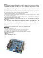
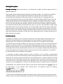
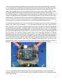
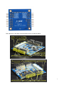
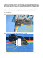
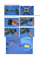
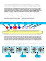
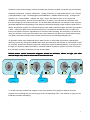
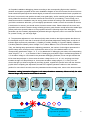
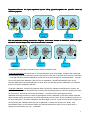
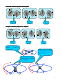
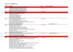
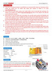
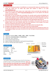
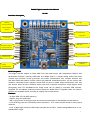
Rabbit Flight Controller User Manual
V1.005
Interface description
description:
GPS(top)
State Light
Ultrasonic(middle)
Battery Voltage
(bottom)
8-CH LED Port
Alarm Port
3 Axis Gyro
BarometerCompas
ARM Chip
s Expansion Board
8-CH Motor/Servo
8-CH Receiving
3-Axis
Accelerometer
USB 接口
Brief Decription:
This Flight controller adopts 32 Digits ARM CPU and latest sensor with Independent research and
development software, ensuring stable,safe and reliable flight in a simple setting suface.The board
contains high precision tri-axis gyroscope and tri-axis accelerometer with compact structure and
size.With stable and balance function without any aditional board.Multi-function: can be connect with
ultrasonic, barometer,tri-axis magnetic sensor,GPS etc.,thus to realize height lock,direction lock, and
self- lift-and- down function.8 Channel remote input and 8 Channel motor/servo output.Support aerial
photography and PTZ Self-Balance.The output mode can be setted by user.With USB interface,
Upgrades PC and adjusts parameters without Expansion Board.With PC upgrade tools,it can improve
program and upgrades online according to majority user's requirements .
Features:
- 32 digits ARM CPU,50 MHZ frequency
- Support 140g mini quadcopter.
- With high precision tri-axis gyroscope and tri-axis accelerometer for self-stability and self-balance.
- 8 CH receiving ports,can set auxiliary switch channels or PTZ control channel except 4 main joystick
channels.
- 8-CH 16 digits high precision PWM output channels,can set 50Hz~500Hz analog/didital servo or nonstandard ESC singal.
1
-Supports
mix-control:GIMBAL,BI,TRI,QUADP,QUADX,Y4,Y6,HEX6,HEX6X,OCTOX8,OCTOFLATP,OCTOFLATX,
FLYING_WING,FIEXD WIND mode and so on. can be added other modes according to users
requirement.
- With USB interface and PC upgrade tools,convienent for users to set parameter,and download the
newest program.
- 8 LED singal to indicate various mode, convinient to set parameters anytime even for a tiny adjustment.
Can connect color LED strip, makes magnificant and unique night flight.
- Supports 4S battery Voltage test, ensure to test each battery.
- Provide alarm port,facilitate users to set low voltage alarm, the alarm sound will be quicker and quicker
with the voltage is lower and lower.
- With ultrasonic port, makes precision height lock within 2 meters (the best effect with flat ground),
switch to barometer height lock out of 2 meters.
- With equipment self-detection function, make sure safty flight . with sound and light signal during the
self-detection.
- With high precision tri-axis magnetic sensor,barometer and GPS port etc.,facilitate users to add
functions such as automatic lift and landing and return.(just buy additional board and upgrade the
software online)
- With Independent research and development software, can improve or add new functions as users
requirement.
- Output mode optinal: Default ESC output 330MHZ. servo signal output 47HZ.
Specifications
Specifications:
- Alarm Voltage setting: 2.8 V~3.7V
- Gyroscope: +-2000dps,16 digits resolution ratio, response time:1000HZ
- Accelerometer: -8G,14 digits resolution ratio, response time:800Hz
- Input Voltage:4~6V (provided by a ESC,too high voltage will burn the board)
- Board Size:5.5mmX5.5mm
- Weight:20g
- Working Temperature: -40~+85℃
The product is shown as below:
2
Setting Description:
Package including: flight control board x1, the Dupont line x1,alarm x1,battery voltage test line x1,
upgrade USB line x1
Initial settings: please download and decompress the software package into a folder, then install the
USB driver program, connect the flight control board to a computer with mini USB line, this will
automatically power the flight control board, the light on the board will be on rolling light state, the
computer will prompt that there is a new USB equipment, and automatically install the driver, when the
system prompts that the new USB equipment which is available, see which serial port the new USB
equipment CH340 map into on the system management interface port display, the default is ( COM3 ),
then you can open the setting tool sofeware, if there is port error from the system, please according to
your computer serial port select communication port, when you correct it, the parameters of flight control
board will be shown on the software interface. If it is not the default 4 axis X mode, 330Hz output mode,
please according to your frame select your multi axis mixed control mode, then according to your ESC
select the output mode. Parameter setting and selection will be saved at the moment, there is no need to
adjust other parameters temporarily. Finally remove the USB equipment from computer and disconnect
flight controller and computer.
Installation guide:
1.Installation: according to your chosen frame mode make your frame stable,mount the flight control
board with LED light toward the front, plastic pillars are recommended for reducing vibration and
resisting impact.Try to advoid the copper pillar,as the 4 metal holes on the flight control board are
connected to the power supply cathode,it may cause short circuit easily. If you want to further reduce the
vibration, you can have the 2mm ~ 5mm thick foam double-sided tape, but do not use springs, rubber
bands such elastic objects. For flight control board is a precision electronic device, please pay attention
to waterproof and avoid mechanical collision, and horn, iron such magnetic material shoud be kept away
as far as possible from the magnetic sensor at least more than 5cm when installation,If you add GPS,
the antenna should not be covered by metal objests.
2. Connection: the flight controller requires at least 4 receivers, up to 8 channels, correspondingly
connect remote control receiver and flight controller receiving channel by channel name(function) with a
dupont line.The receiving channel from bottom to top respectively are: ( 1,Aileron 2,Elevator 3,Throttle
4,Direction,the rest is the auxiliary channel), then, please set remote control into a fixed wing mode, trim
lever all turn to zero, adjust each channel ratio to the default 100%, then connect the control board with
computer, open the debugging tool, select the corresponding COM port to flight controller. Its parameters
is all displayed. Then make the remote control on and click the channel data button
which on
the right bottom of tool software, each channel data is all displayed, shown as following:
3. Remote Control Initial Setting: operate each channel joystick, observe whether the receiver channel
position is right, if not please change flight controller lines, the effective range data should between 1000
3
~ 2000, the middle is about 1500.Different brands of remote control will be a little different. Then see if
the channel direction is accurate, the requirement RC controller joystick direction is: throttle and elevator
is down-small (1000)/up-great (2000), the aileron and direction is left-small (1000)/ and right-great
(2000). If the joystick direction is wrong, please have the remote control reverse setting. Finally, operate
the throttle joystick to the end and the channel minimum value must be less than 1100, preferably
between 1020 ~ 1090,if not,you should adjust the throttle trim lever or rudder trim lever on remote control
panel to meet this requirement. Regardless of corresponding channel of remote control is on left or right
or other position, the joystick instruction is only related to the channel name. Output channel supports up
to 8 axis, if the motor is 6 axis or less, the rest of two channels will automatically become PTZ pitch and
roll to increase servo stability to control channels.You can set reverse and ratio by the tools.
4. Throttle Range Calibration: Connect your motor and ESC to flight control board by the corresponding
channel, from bottom to top is channel 1 ~ 8, do not install the propeller at this time. Connect the two
pins ( TXD, RXD ) with a dupont line like the diagram, then power it, the flight controller will automatically
get into throttle range calibration, the indicator light will flash quickly at first for 4 seconds, the ESC adjust
by itself with music, after that sounds “Beep,Beep~” to confirm throttle maximum value (1900), and then
the flight control indicator light slowly flash for 2 seconds, then the ESC sounds “Beep,Beep,Beep”,at
last once “Beep~” to comfirm the throttle minimum value (1100). Finally flight controller is in initialize
self-detection state, the indicator light is in a rolling state. This can refer to ESC user manual to see if the
automatic throttle calibration is successful, if the ESC is special thus it can not be automatic calibration,
you should do it by manual operation. Before the manual operation you must set the remote control
throttle minimum range between 1020~1090. The calibration method please refer to the ESC user
manual.The ESC which you have calibrated before should calibrate the throttle range again according to
Rabbit’s requirements.Or it will have some bad phenomenons such as vibration,motor stop etc.
Connect the two pins (TXD, RXD) with
dupont line,power on, automatically get
into throttle calibration
5.Connect the ultrasonic,alarm,expansion board and GPS, please according to flight control board
backside screen printing. The screen printing is shown as below,pay attention to the corresponding pins
of the screen printing.
4
Both side pins on the flight control board are shown in detail as below:
Middle row to ultrasonic
wave (+5V,TRIG,ECHO,
Top row to GPS
(+5V,TX,RX,GND)
CH7~CH0 8-CH input
+5V
GND
Battery balance (B4,B3,B2,B1,GND)
The last 2-CH M6、M7
to PTZ servo
To LED0/1/2/3/4/5/6/7
To wireless alarm
5
M0~M7 8-CH output
ESC +5V input
GND
GND
LED+5Voutput
6.Warning! To reconfirm the connection without error! Please ensure careful confirmation,for the wrong
connection may burn down your ESC or flight control board! Especially the battery detecting line cannot
be connected to other pins.The red line connect to the athod,green line connect to the cathod (ground), if
it is a 3S battery, balance head should be aligned with the cathode. It has more than 12V high
voltage!Ultrasonic wire athod and cathod can not be reversed; Make sure the voltage is normal before
power on; the receiver can not connect to ignition, servo or other large current load! The output power
capacity of flight control board is only 200mA.Note:Only to provide paid repairment service for
man-made damage!!!
Battery detecting line to flight control board connection is shown as below:
Protection casing
Protection casing
Blue is negative(ground)
Battery detecting line to the bottom
row,red line is possitive
Battery detecting line to the battery balance head is shown as below:
Red line is possitive
Blue line is negative
Battery balance head
Red line is possitive
Battery balance head
Black line is negative
Battery negative plug to negative notch
If only 3S battery,there is no this line
Ultrasonic sensor is fixed below the frame with plastic cable tie and faces the ground, pay attention to
6
the athod and cathod color, shown as below:
LED light strip extension board connection diagram is as following (voltage expansion board’s athod and
cathod are connected with battery’s):
7
7.The power self-detection: Put the aircraft on a horizontal place without vibration, power it, do not
connect the battery detecting line at the moment, the ESC will be on its initialization, flight controller
sounds “Beep~” once,the indicator light will be on a rolling flash which means it is on self-detection,
then connect the battery voltage detecting plug to battery charging balance head.The 8 lights on flight
control board from left to right on behalf of (1,battery 2,remote control, 3,gyroscope, 4,accelerometer, 5
magnetic sensors 6,barometer 7,ultrasonic 8,GPS ) 8 equipments. The corresponding light will light if the
initialization is successful, not light if it is undetectable or not selected.You can turn on the remote
controller first or after power the aircraft, to avoid the receiver out of control,the setting befor is regarded
as a normal signal self-detection, you must operate any a joystick in self-detection. When the flight
controller receive the remote control signal it will sounds " beep" once, then make the throttle to the
minimum position, other joysticks wait still, during detection process the indicator light will roll once and
then stop for 2 seconds to display the self-detection state,when all equipments pass the self-detection,
flight controller will give a long sound "Beep - --", then be into a dormant state (lock).
Battery
Remote control
Gyro
Accelerometer
Magnetic
sensor
Barometer
GPS
ultrasonic
Rolling light runs for 2 seconds then stops for 2 seconds, light bright which means the self-detection is ok.
8.Operation under dormant state(lock): in dormant state,the indicator light would be bright-dark-bright,
change always like this,just like the breathing effect,that means the aircraft is in a dormant state,at this
time it can not fly even if you operate all the joysticks,very safe.Operate the joysticks in dormant state for
a few times which can set the corresponding parameter. Or enter the sensor calibration, this has detail
description below. In a dormant state the throttle is on the minimum position while aileron should operate
to left the minimum position for more than 3 seconds, then enter the active state(unlock). Can receive
the take-off instruction anytime.
Unlock remote control instruction diagram: throttle to minimum, aileron to left, the other channel
keeps still, lasts for more than 3 seconds and unlock
Japanese
mode
American
Mode
Chinese
Mode
8
9.Remote control switch settings: remote controller can connect to at least 4 channels, up to 8 channels.
Channels in sequence: 1,Aileron 2,Elevator 3, Throttle 4,Direction 5, Flight mode switch ( Low - Primary
( Self stabilization ); High - Developing(Non self stabilization ); Middle-Advanced (3D) ), 6,Height Lock
Switch ( Low - closed; Middle – Height Lock; High – High Lock wigh CF open; if you choose the
ultrasonic and barometer ,they will connect perfectly in 2 meters ), if the channel is in different order,
then just change the connection line order. The channel data and direction can be seen in the computer
parameter adjustment tool,operating to left should be small and oprating to right should be great fot the
aileron and direction joystick.The Throttle minimum value must be less than flight controller recomended
( 1020~1090),if too great it can't lock and unlock.You can adjust the throttle trim lever or rudder trim
lever on the panel to meet the requirement.For the other channel setting, the maximum is not less than
1800, the minimum is not more than 1200.It also can be setted as you like,but too small channel range
may lead to that cannot identify some remote instruction such as unlocking,calibration etc.
10.Operation under active state(unlock):in a state of action, if the throttle is the lowest, operating the
direction joystick can change the indicator light mode and color,there are 28 kinds of combination in total
for choosing, operate the elevator joystick can change the rhythm of blinking patterns. If you want to end
the flight or it needs to replace the battery, operate the aileron joystick to right for more than 3 seconds,
then the flight controller would enter into the dormant state.
Unlock remote control instruction diagram: throttle to minimum, aileron to right, the other
channel keeps still, lasts for more than 3 seconds and lock
Japanese
mode
American
Mode
Chinese
Mode
11.Check the motor positive and negative: if the motor positive and negative is different from the
program, then exchange any two motor plugs of the corresponding ESC, if the direction is right,you can
install the propellers and debug.
9
12.Propeller installation debugging: please according to the corresponding flight mode, install the
posstive and negative propeller as the motor installation diagram on the user manual, the face which has
words should be upward,push the throttle slightly to rotate the motor and see whether each propeller has
lift force,if not,recheck it and grab the aircrafe (must grab tightly, and be careful!),push slightly the throttle,
slowly shake the aircraft to see whether the aircraft is the block of your shaking, if not,but help you to
shake,that means the installation may be wrong, please recheck according to the attached diagram. If
you feel the resistance still exists, you can slightly operate each rudder ,to see if the controller is reverse,
if the direction is reverse, you should set the channel reverse switch. Please observe if the motor and
properller have eccentric vibration during refueling process, great vibration would influent the stable flight,
please perfect the dynamic balance of the properller before the following steps.Each debugging
parameter can be constantly adjusted and perfected during the flight test, which can make the aircraft fit
for yourself! Finally, you can begin flight.
13. The parameter adjustment: in the dormant (lock) state, throttle to the highest,operate the aileron to
the lowest(left end) for more than 3 seconds into the parameter adjustment setting state, at this time 8
indicator lights represent 8 parameters ( 1,Stability 2,Auxiliary Stability 3, Dynamin Stability 4,Balance
5,Auxiliary Balance 6,Battery Alarm Voltage Trim 7,Aileron Balance Trim 8, Elevator Direction Balance
Trim), the flashing lamp represents the adjusting parameter, the number of other lights represents the
specific setup value, 8 lamps in total, represent the value of 0 to 8, the default value is 4, the
corresponding parameters of light 1, 2, 3, 4, 5 is added with PC debugging tool value; the corresponding
value of light 6, 7, 8 +-4 on the base of the PC debugging tool( like the light 6: default lamp position is
4, if the alarm voltage is 3.5V setted in the parameter debugging software, minus one light towards the
left is three lamps always on, that means the alarm voltage minus 0.1V, is 3.4V; and plugs one lamp
towards the right is 5 lamps always on, that means the alarm voltage plugs 0.1V, is 3.6V).You can
choose the light you’d like to regulate by the lifting joystick, regulate the specific value with the direction
joystick.After completing the adjustment, throttle to the highest,operate the aileron to the maximum
position for more than 3 seconds, save the parameters and exit setup state, return to the dormant state.
Parameter setting instruction diagram: Lock state, throttle to maxmum, aileron to left, the other
channel keeps still, lasts for more than 3 seconds
Japanese
Mode
Which number light
represents which
(3)parameter
American
Mode
Chinese
Mode
The number of lights on
represents the parameter data
(4)
10
Regulation:Choose the light regulated by the lifting joystick,regulate the specific value by
direction joystick
Japanese
Mode
American
Mode
Chinese
Mode
Exit the parameter setting instruction diagram: Lock state, throttle to maxmum, aileron to right,
the other channel keeps still, lasts for more than 3 seconds
Japanese
Mode
American
Mode
Chinese
Mode
14.Calibration:let the flight controller enter a dormant state(lock) first.
Horizontal Calibration,put the aircraft on a horizontal place as far as possible, throttle to the lowest and
rock the lifting joystick up,direction joystick to the right for more than 3 seconds and it sounds once“Beep
-”and then into the horizontal calibration,at this time ensure the aircraft on a horizontal state, the light
are running during the calibration, after the end of calibration, it would automatically return to the
dormant state.Note: Horizontal calibration is done when you feel the previous calibration is not ideal,or
there is no need to frequently calibrate.
Compass Calibration, avoid strong magnetic field or great iron magnetic material within 5 meters, the
open air is the best!When the throttle is the lowest,rock the lifting joystick up, direction joystick to the left
for more than 3 seconds and it sounds once“Beep-”and then into the geomagnetic sensor
calibration,will beep sound into a state of geomagnetic sensor calibration, at this time please rotate the
flight controller slowly and uniformly 2 rounds respectively around 3 axis. Shown as following: be sure to
be slow and uniform, the better calibration, the better flight you have, a total of 60 seconds, the light are
running during the calibration,after the end of calibration, it would also sound once “Beep-” and
automatically return to the dormant state.If you feel that the direction effect is not so good when it
change the environment you can recalibrate.
11
Horizontal calibration joystick rock diagram:
American
Mode
Japanese
Mode
Chinese
Mode
Compass calibration joystick rock diagram:
American
Mode
Japanese
Mode
Chinese
Mode
1,Rotate
slowly
and
uniformly 2 rounds in
horizontal state
M
M
M
M
3,Rotate slowly and uniformly
2 rounds during 20 seconds
with the side up
2,Rotate slowly and uniformly
2 rounds during 20 seconds
with the head up
M3
M2
M1
M0
M
2
M
3
M
0
M
1
12
15, Fun flight: after the self adjustment above, you can enjoy the joy of flight! There are 3 flight
modes,you can switch it by 3 section switch of channel 5.
1, The primary mode: (minimum position of 3 section switch ) with self stablity function, operate the
rudder slightly to correct and it can fly well, this mode has the best effect in windless environment.
2, The normal mode: (maxmum position of 3 section switch ) is also called the developing mode, the
aircraft somehow has a stable performance, operating the rudder and the aircraft will change the current
posture and try to maintain.This mode has certain resistance to unexpected external force, like the wind
etc. The flight posture needs pilot to correct constantly, relatively quick reaction to operate the rudder,
but it cannot work for the intense action. This mode is suitable for most people from entry to the less
violence of flight.
3, The motion mode: (middle position of 3 section switch ) also called stunt mode and 3D mode, the
aircraft has high flexibility, quick reaction to operate the rudder.It is very sensitive to rudder during the
flight process, needs pilots’ quick judge and control ability. This mode can make people as the acme of
perfection high difficulty movement. This mode can do some amazing and astonishing stunt.It is also the
very mode to be crash.
Height Lock and CF switch: when you installed ultrasonic or pressure sensor and magnetic sensor,it can
achieve height lock and CF mode flight by channel 6 switch.
When turn on the height lock,adjust slowly the throttle to the requirement height,stop and the height lock
process will automaticly be instead of the throttle and then lock the height.If you want to change the
height, as long as adjust the throttle and it will unlock temporarily,until the throttle stops it will
automatically enter the height lock again. Ultrasonic height lock need the flat terrain below without messy
objects or protrusion.It needs barometer above 2 meters,and barometer is affected from weather,
temperature, pressure etc.The barometer can be covered with thick foam double-sided tape to eliminate
the effects of wind.
Ensure to calibrate the magnetic sensor before you turn on the CF function, rough calibration will affect
the effect of flying.After magnetic sensor calibration, it need to verify the effect.Put the aircraft on the
ground, turn on CF function, unlock and slowly refuel and rock lifting and aileron, observe if the aircraft
reactive direction away the ground is the same with the unlock state,at least test 4 directions, it had
better check the 45 degree direction. if you ensure all the direction is accurate,you can have the flight
test now. Note: CF mode flight angle error will increase under high speed rotating,when there are great
lifting and aileron motion, angle error will also increase! Therefore, great rudder flight or 3D mode is not
recommended to turn on the CF function.
If you want to get the aircraft to stay on a specified location (range ) in the air, you need to open GPS
switch to help the location lock, if you want the FPV automatic return function you must also install the
GPS option.
16.PTZ connection and adjustment: if the motor channel is less than or equal to 6, then the channel 7
and channel 8 would be automatically converted to 2 axis PTZ stability output,the channel 7 ( M6 )
connect to pitch servo, the channel 8 ( M7 ) connect to the rolling servo, the compensation ratio and
13
direction can be adjusted through the parameter adjustment tool, the value represent the ratio, +-
represent the positive and negative of direction.
Remote control switch selection suggestions: channel 5 and channel 6 recommend using two three
sections switch, if the channel 5-6 is vacant, flight controller default this two channels are on low
possition: channel 5 mode defaults to the self stability mode, 6 channel defaults to the closed height lock.
Upgrades and points for attention: in order to add new functions or improve the software according to
feedbacks of some model friends, we will provide software upgrade service, the firmware can be
upgraded by computer usding the debugging tools we provided. Every time the software version is
upgraded,all the original parameters will be refreshed to default values, you should have the horizontal
calibration and compass calibration again, check and modify the parameters so that it can be used
normally!
14
11 Kinds of Multi-mode Installation Diagram
BI
M0
M2
M3
M1
M2
TRI(Y3)
M1
M3
M0
M3
M1
M2
M0
QUAD X(4X)
M3
QUAD +(4+)
M1
M2
M0
15
Y4
M1
M3
M2
M0
M2
M1
M5
M4
Y6
M0
M3
M4
HEX6
M1
M3
M2
M0
M5
M3
M1
6X
M4
M5
M2
M0
16
M3
M1
M7
M5
M2
M0
M6
M4
8X
M4
M0
M1
M5
M7
8P+
M2
M3
M6
M0
M5
8X
M4
M1
M3
M6
M2
M7
M2
Fixed Wind Mode
M0
M1
M3
17