1
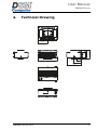
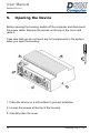
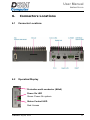
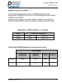
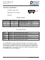
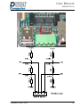
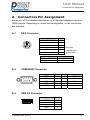
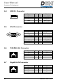
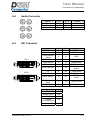
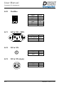
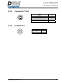
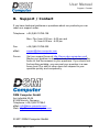
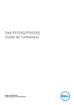
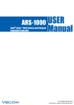
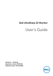
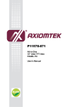
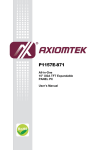
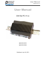
User Manual
DIN Rail PC H1-A
User Manual
DIN Rail PC H1-A
96M1670-Z510
96M1670-Z530
Published: July 22, 2013
User Manual
DIN Rail PC H1-A
This page is intentionally left blank.
2
Published: July 22, 2013
User Manual
DIN Rail PC H1-A
Index
1.
COPYRIGHT .............................................................................................. 5
2.
ACKNOWLEDGEMENTS ............................................................................. 5
3.
TECHNICAL SPECIFICATIONS...................................................................... 7
3.1
3.2
3.3
3.4
3.5
EMBEDDED CONTROLLER ...............................................................................7
CASE..........................................................................................................7
ON REQUEST ...............................................................................................8
OPTIONS ....................................................................................................8
ORDER NUMBER ..........................................................................................8
4.
TECHNICAL DRAWING............................................................................... 9
5.
OPENING THE DEVICE ............................................................................. 10
6.
CONNECTORS LOCATIONS ...................................................................... 11
6.1
6.2
6.3
6.4
6.5
CONNECTOR LOCATIONS ..............................................................................11
OPERATION/DISPLAY ..................................................................................11
SD-CARD SLOT ..........................................................................................12
DC INPUT .................................................................................................12
RS485-INTERFACE .....................................................................................12
Appendix
A.
CONNECTORS PIN ASSIGNMENT (Standard)........................................... A-1
B.
SUPPORT / CONTACT...………………………………………………………………………… B-1
Published: July 22, 2013
3
User Manual
DIN Rail PC H1-A
This page is intentionally left blank.
4
Published: July 22, 2013
User Manual
Copyright / Acknowledgements
1. Copyright
The documentation and the software included with this product are
copyrighted by DSM Computer GmbH. All rights are reserved.
The information contained in this document has been carefully researched
and is, to the best of our knowledge, accurate. However, we assume no
liability for any product failures or damages, immediate or consequential,
resulting from the use of the information provided herein. Our products are
not intended for use in systems in which failures of product could result in
personal injury. All specifications are subject to change without notice.
No part of this manual may be reproduced, copied, translated or
transmitted in any form or by any means without the prior written
permission of DSM Computer GmbH.
2. Acknowledgements
DSM®, Galaxy®, BlueBoard®, NanoServer®, Infinity® and Bluebook® are
registered trademarks of DSM Computer GmbH. Intel®, Pentium®,
Celeron®, Xeon® and Core® are registered trademarks of Intel®
Corporation. Award is a registered trademark of Award Software, Inc. MSDOS®, Windows® and Microsoft® are registered trademarks of Microsoft®
Corporation. PS/2 and IBM are registered trademarks of International
Business Machines Corporation.
All other product names are used only for identification purposes and are
(can be) registered trademarks of the associate owner.
For more information about our products or for technical support and
service please visit our website at: http://www.dsm-computer.com.
Published: May 11, 2011
5
User Manual
This page is intentionally left blank.
6
Published: May 11, 2011
User Manual
DIN Rail PC H1-A
3.
3.1
Technical Specifications
Embedded Controller
-1024 MB DDR2 RAM, 533 MHz
- Intel® US15W SCH system controller hub
- Intel® GMA 500, integrated in Intel® US15W SCH,
up to 384 MB shared memory, max resolution 1920 x 1200
- 2 x GigaBit LAN, Intel® WG82583V
- 1 x VGA (service interface)
- 2 x serial ports RS485,
electrically isolated, 1 x 4-pin connector
- 1 x serial port RS232
- 2 x USB 2.0
- SD-card slot, supports SD-, SDIO- and MMC-cards
- Qseven™ interface: Version 1.11 compliant
- System monitoring, watch-dog timer
- ACPI power management
- Operating temperatures: 0° ~ 45
3.2
Case
Solid high-quality industrial case for DIN rail mounting (35 mm)
- Mounting on DIN rail with connectors facing downwards
- Compatible fitting for electrical cabinet
- Control LEDs (Power on)
- Incl. DIN Rail mounting
- Power supply 24 VDC
- Dimensions WxDxH: 124.5 (7 U) x 90 x 41/55 mm
Published: July 22, 2013
7
User Manual
DIN Rail PC H1-A
3.3
On Request
- In your customer color available
- With your corporate logo
- integrated M-Bus Master (fieldbus for consumption data
acquisition) instead of RS232 resp. VGA
- Integrated digital IO interface
3.4
Options
- Second COM (RS232) instead of VGA
- 3.6 GB Flash onboard (96M1670-Z510 only)
- 7.2 GB Flash onboard (96M1670-Z530 only)
2 years warranty, burn-in, CE-compliant
3.5
Order Number
96M1670-Z510
- Intel® Atom™ Z510 1.1 GHz
- 1.8 GB Flash onboard
- Fanless
96M1670-Z530
- Intel® Atom™ Z530 1.6 GHz
- 3.6 GB Flash onboard
- Fanless, TPM (Trusted Platform Module)
8
Published: July 22, 2013
User Manual
DIN Rail PC H1-A
4.
Technical Drawing
124,5
54,71
41,21
51,21
62,25
28,97
49
90
Published: July 22, 2013
9
User Manual
DIN Rail PC H1-A
5.
Opening the Device
Before opening the housing, switch off the computer and disconnect
the power cable. Remove the screws on the top of the cover and
raise it.
Take care that you do not touch any hot components in the system
when you open the housing!
1. Place the device on a soft surface to prevent scratches.
2. Loosen the screws at the top of the housing.
3. Carefully raise the cover.
10
Published: July 22, 2013
User Manual
DIN Rail PC H1-A
6.
Connectors Locations
6.1
Connector Locations
6.2
Operation/Display
Protective earth conductor (M4x8)
Power On LED
Green: Power On system.
Status Controll LED
Red: Access
Published: July 22, 2013
11
User Manual
DIN Rail PC H1-A
6.3
SD-Card Slot
For using of memory cards the unit has a SD-Card Slot on board.
- controller provide by Qseven modul.
- Slot supports SD-, SDIO- and MMC-cards
- maximum Data range is 4 Bit.
- Over current secured by Power Switch with over current detect
output.
Connector specification:
- Connector type: SD-Card Slot
Hirose DM1AA-SF-PEJ
- Pinning: to find at SD-Card Specification
6.4
DC Input
For power you have to use +24V DC.
Connector specification:
- connector type: 2 pin .
GND
Würth 691 313 710 002
6.5
RS485-Interface
For communication there are two RS485 Ports on board.
- Serial Controller USB-Chip (FTDI) or SuperIO
Other one is needed for RS232.
- In standard configuration RS485 is driven via super IIO, RS232 is
driven via USB chip (FTOI). Inverse configuration is available on
request.
- RS485 driver: Sipex SP483E
- Termination with 120 Ohm resistor with internal DIP-switch
- Pull-Up / Pull Down failsafe resistor 620 Ohm with internal
DIP-switch
12
Published: July 22, 2013
User Manual
DIN Rail PC H1-A
RS485 Control over RTS#
The transmit and receive control of RS485 interface at the
baseboard Q7-MB-PICO2 occurs over RTS#-Signal at the RS485interface used UART.
Therefore the 16550 compatible UARTs COM A and COM B of
SuperIO W83627DHG from manufacturer Winbond will be used.
Assignment: UART interface - connector
UART
CONNECTOR INTERFACE
COM A
COM B
PIN 1 + 2
PIN 3 + 4
COM1
COM2
Controlling RTS#-Signals for transmit and receive
RTS# Signal
Level on
Transceiver
Level on
SuperIO
Status
Register
transmit
High
Low
aktiv
1
receive
Low
High
inaktiv
0
Published: July 22, 2013
13
User Manual
DIN Rail PC H1-A
Connector specification:
- connector type: 4 pin .
Pin1
Würth 691 313 710 004
- Pinning:
RS485 Interface
PIN
1
2
3
4
Signal
B1
A1
B2
A2
function
diff. data signal neg.
diff. data signal pos.
diff. data signal neg.
diff. data signal pos.
COM1COM1+
COM2COM2+
Termination switch
SW1
SW2
SW3
SW4
SW5
SW6
COM1COM1
COM1+
COM2COM2
COM2+
Idle termination (620 Ohm)
differential termination (120 Ohm)
Idle termination (620 Ohm)
Idle termination (620 Ohm)
differential termination (120 Ohm)
Idle termination (620 Ohm)
The RS422-BUS needs a failsafe-termination. If no party is active
the bus will be on defined level over resistor. Only one termination
for each Bus required. If more than one termination the system will
have malfunction. The switch 1 and 3 for COM1 and switch 4 and 6
for COM2 has to be set together.
14
Published: July 22, 2013
User Manual
DIN Rail PC H1-A
Published: July 22, 2013
15
User Manual
DIN Rail PC H1-A
This page is intentionally left blank.
16
Published: July 22, 2013
User Manual
Connectors Pin Assignment
A. Connectors Pin Assignment
Below you will find detailed descriptions of all standard interfaces found in
DSM systems. Depending on model and configuration, not all connectors
are available.
A.1
PS/2 Connector
6
5
3
4
2
1
Signal
Data
n.c. / Mouse Data*
GND
5V
Clock
n.c. / Mouse Clock*
Color Code
purple
green
A.2
* On some
computers for
splitter cable.
Description
Keyboard
Mouse
COM RS232 Connector
5 4 3 2 1
9 8 7 6
A.3
Pin
1
2
3
4
5
6
Signal
DCD
RXD
TXD
DTR
GND
Pin #
1
2
3
4
5
Signal
VBUS
DD+
GND
Pin #
1
2
3
4
Pin #
6
7
8
9
Signal
DSR
RTS
CTS
RI
USB 2.0 Connector
1 2 3 4
Published: June 4, 2013
A-1
User Manual
Connectors Pin Assignment
A.4
USB 3.0 Connector
9 8 7 6 5
1 2 3 4
A.5
5
1
6
15
Signal
StdA_SSRXStdA_SSRX+
GND_DRAIN
StdA_SSTXStdA_SSTX+
Signal
Red
Blue
GND
Green GND
n.c.
ID0
H / C SYNC
ID3 / SCL
Pin
1
3
5
7
9
11
13
15
Pin
2
4
6
8
10
12
14
Signal
Green
ID2 / Reserved
Red GND
Blue GND
Sync GND
ID1 / SDA
V SYNC
11
Pin
1
2
3
4
Pin
5
6
7
8
Signal
n.c.
RXn.c.
n.c.
8
Pin
1
2
3
4
Pin
5
6
7
8
Signal
D3D2D4+
D4-
Signal
TX+
TXRX+
n.c.
GigaBit LAN Connector
1
A-2
Pin
5
6
7
8
9
100 MBit LAN Connector
1
A.7
Pin
1
2
3
4
VGA Connector
10
A.6
Signal
VBUS
DD+
GND
8
Signal
D1+
D1D2+
D3+
Published: June 4, 2013
User Manual
Connectors Pin Assignment
A.8
Audio Connector
A.9
Signal
Side Surround
Rear Surround
Center/LFE
Pin #
Orange
Black
Grey
Pin #
Blue
Green
Pink
Signal
Line In
Line Out
Microphone
Signal
TMDS Data2TMDS Data2+
Pin #
1
2
Pin #
13
14
Signal
TMDS Data3+
+5VDC Power
TMDS Data2/4
Shield
3
15
GND
TMDS Data4TMDS Data4+
DDC Clock
4
5
6
16
17
18
Hot Plug Detect
TMDS Data0TMDS Data0+
DDC Data (all)
7
19
TMDS Data0/5
Shield
n.c.
TMDS Data1-
8
9
20
21
TMDS Data5TMDS Data5+
TMDS Data1+
10
22
TMDS Clock
Shield
TMDS Data1/3
Shield
11
23
TMDS Clock+
TMDS Data3-
12
24
TMDS Clock-
Signal
Analog Red
Analog Green
Analog Blue
Pin #
C1
C2
C3
Analog
Horizontal Sync
C4
GND
C5
DVI Connector
DVI-I
1
9
17
8 C1 C2
C5
16
24 C4 C3
DVI-D
1
9
17
8
16
24
Published: June 4, 2013
C5
A-3
User Manual
Connectors Pin Assignment
A.10
FireWire
2
1
4
3
6 5
A.11
A.12
A.13
A-4
Signal
+12V
GND
TPB−
TPB+
TPA−
TPA+
Pin #
1
2
3
4
5
6
Signal
Phase / Neutral
GND
Phase / Neutral
Pin #
left
center
right
Signal
+12V
GND
Pin #
Pin
Shield
Signal
+12V
GND
Pin #
1,2
3,4
AC In 100 ~ 240V
DC In 12V
DC In 12V (4 pin)
1
2
3
4
Published: June 4, 2013
User Manual
Connectors Pin Assignment
A.14
Composite TV-Out
43
2 1
A.15
Signal
GND (Y)
GND (C)
Intensity (Luminance) (Y)
Color (Chrominance) (C)
Pin #
1
2
3
4
S-VIDEO Out
Signal
Video FBAS Y
GND
Published: June 4, 2013
Pin #
Pin
Shield
A-5
User Manual
Connectors Pin Assignment
This page is intentionally left blank.
A-6
Published: June 4, 2013
User Manual
Support / Contact
B. Support / Contact
If you have technical problems or questions about our products you can
reach our support under:
Telephone: +49 (0)89 15798-128
Mon.-Thu. from 8:00 am - 6:00 pm and
Fri. from 8:00 am - 4:00 pm
Fax:
+49 (0)89 15798-225
eMail:
[email protected]
Forum:
Visit our support forum at http://forum.dsm-computer.com!
Maybe your problem is already solved. Use the search in the
forum to find the answers to your questions. If you should not
find anything suitable, you can post your question in a new
forum post. Our staff or other users will respond to your
question quickly and competently.
DSM Computer GmbH
Am Loferfeld 50-54
81249 Munich, Germany
Telephone: +49 (0)89 15798-0
eMail: [email protected]
Web: http://www.dsm-computer.com
© 2011 DSM Computer GmbH
Published: May 19, 2011
B-1
User Manual
This page is intentionally left blank.
B-2
Published: May 19, 2011