1
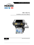
VEO 600 Video Web Viewing System User Manual EN MI 2-272 1 A CONTENTS INTRODUCTION 1-1 About these operating instructions ...................................................................... 1-1 CE marking .......................................................................................................... 1-1 Language ............................................................................................................. 1-2 Product overview .................................................................................................. 1-2 Model number key ........................................................................................... 1-3 SAFETY INSTRUCTIONS 2-1 Safety symbols ..................................................................................................... 2-1 Basic safety information ....................................................................................... 2-3 Hazards ................................................................................................................ 2-3 SYSTEM COMPONENTS 3-1 Power supply connections .................................................................................... 3-3 INSTALLATION 4-1 Installation requirements ..................................................................................... 4-1 Earth grounding .............................................................................................. 4-2 Typical installation positions ................................................................................ 4-3 Installation options .............................................................................................. 4-5 Installing the camera ............................................................................................ 4-7 VEO 600-M/R .................................................................................................. 4-7 VEO 600-MTZ .................................................................................................. 4-8 Adjusting the camera position ....................................................................... 4-11 Remote keyboard .......................................................................................... 4-12 Sensor signal settings ........................................................................................ 4-13 Gear sensor installation...................................................................................... 4-20 Gear selection ................................................................................................ 4-20 Mounting the gear sensor .............................................................................. 4-21 Setting the gear tooth information ................................................................ 4-22 Using dual sensors ........................................................................................ 4-23 Rotary encoder .............................................................................................. 4-24 KT-5 optical sensor ....................................................................................... 4-25 Monitor setup..................................................................................................... 4-26 OPERATION 5-1 Turning on the system ......................................................................................... 5-1 System language .................................................................................................. 5-1 Main screen .......................................................................................................... 5-2 Keypad button functions ...................................................................................... 5-3 Operation modes ............................................................................................. 5-5 Image navigation ............................................................................................. 5-6 Image rotation ................................................................................................. 5-7 www.maxcessintl.com Fife VEO 600 MI 2-272 1 A CONTENTS Lens control..................................................................................................... 5-8 Brightness ....................................................................................................... 5-9 Screen split/freeze ........................................................................................ 5-10 Menu functions .................................................................................................. 5-11 Gamma correction ......................................................................................... 5-11 CMYK value detection .................................................................................... 5-12 Print meter .................................................................................................... 5-13 Slow shot ....................................................................................................... 5-14 Roll shooting ................................................................................................. 5-15 Reference line ................................................................................................ 5-16 TROUBLESHOOTING 6-1 MAINTENANCE 7-1 Maintenance schedule .......................................................................................... 7-1 Strobe lamp replacement ..................................................................................... 7-2 Ordering information ....................................................................................... 7-2 VEO 600-M/R .................................................................................................. 7-3 VEO 600-MTZ .................................................................................................. 7-4 SPECIFICATIONS 8-1 SERVICE 9-1 www.maxcessintl.com Fife VEO 600 MI 2-272 1 A 1-1 INTRODUCTION About these operating instructions All of the information herein is the exclusive proprietary property of Maxcess International, and is disclosed with the understanding that it will be retained in confidence and will neither be duplicated nor copied in whole or in part nor be used for any purpose other than for which disclosed. Copyright 2015, all rights reserved. Periodically there will be updates to this manual. The latest version is available on our website or by calling the number listed on the back page of this publication. This web viewing system must not be installed or used in a machine or system which does not comply with the machinery directive 2006/42/EC. This web viewing system was designed and manufactured to be installed as partly completed machinery into a machine or partly completed machine. The instructions must be read and used by all persons who have the responsibility of installing and maintaining this video web inspection system. These instructions must be retained and incorporated in the technical documentation for the machine or partly completed machinery into which the web viewing system is installed. CE marking The VEO 600 Web Viewing System complies with the 2006/42/EC Machinery directive, the 2004/108/EC Electromagnetic Compatibility directive, and the Low Voltage Directive 2006/95/EC. www.maxcessintl.com Fife VEO 600 MI 2-272 1 A 1-2 INTRODUCTION Conventions used in this manual All dimensions and specifications are shown in the format mm [inches] unless otherwise specified. Language These are the original instructions, written in English. Product overview The VEO 600 web viewing system uses a camera unit to capture images of a moving web material that is to be inspected, normally inspection of a printed web. A strobe lamp, integrated into the camera unit, illuminates in time with the machine speed to capture or "freeze" images on the moving web to allow a visual inspection, via monitor, by an operator. The camera unit can be positioned manually or by motorized control over the web material. A sensor synchronizes capturing of images with the moving web material. The display of the print image that is being observed appears on a monitor. The camera is operated either by a built-in keypad or by an external keyboard (for remote operation of the VEO 600). The individual components of the system are connected to a central power supply. www.maxcessintl.com Fife VEO 600 MI 2-272 1 A 1-3 INTRODUCTION Model number key Product Version Keyboard Motorized VEO 600-M On camera No VEO 600-R Remote with line No VEO 600-MTZ Remote with line Yes The VEO 600-M is suitable for narrow rotary presses or combination rotary presses. There is a keyboard on the camera and the unit is moved by hand. The VEO 600-R is suitable for narrow or wide presses. The keyboard is remote and the unit is moved by hand. The VEO 600-MTZ is suitable for narrow or wide presses. The keyboard is remote and the unit has a motorized movement. www.maxcessintl.com Fife VEO 600 MI 2-272 1 A 2-1 SAFETY Instructions for use Problem-free and reliable operation of the VEO 600 requires that the system must be properly transported, stored, installed, and placed in operation. Proper operation will ensure a long service life for your system. Only persons who are acquainted with the installation, commissioning, operation, and maintenance of the system and who possess the necessary qualifications for their activities may work on the VEO 600. Note: The safety information may not be comprehensive. Please note the following: The content of these operating instructions Any safety instructions on the device The machine manufacturer’s specifications All national, state, and local requirements for installation, accident prevention, and environmental protection Safety symbols The safety instructions and symbols described in this section are used in these operating instructions. They are used to avoid possible dangers for users and to prevent material damage. SIGNAL WORD Source of danger and its results Avoiding dangers The signal word DANGER refers to the danger of death or serious bodily injuries. The signal word WARNING refers to the danger of moderate to severe bodily injuries. The signal word CAUTION refers to the danger of slight to moderate bodily injuries or material damage. www.maxcessintl.com Fife VEO 600 MI 2-272 1 A 2-2 SAFETY Symbols used The following safety identification symbols are used in these operating instructions. WARNING/CAUTION – General danger or important note Reference to general hazards that may result in bodily injuries or damage to device or material. DANGER – Danger due to voltage, electric shock Reference to danger of injury caused by electric shock due to voltage. WARNING – Danger due to cutting Reference to danger of injury caused by sharp edges WARNING – Danger due to crushing/pinching Reference to danger of injury caused by moving components WARNING – Injury or equipment damage can result from fire. Reference to danger of injury or damage caused by fire CAUTION – Equipment damage can result from static charge. Reference to general caution that can result in damage to device. Reference to important information www.maxcessintl.com Fife VEO 600 MI 2-272 1 A 2-3 SAFETY Basic safety information Proper use The VEO 600 is intended to be installed indoors in proximity to a moving web on a printing press for the purpose of inspecting image quality during the printing operation. Improper use Operation outside the technical specifications Operation in an Ex-area or intrinsically safe area Outdoor operation Any other use than the proper use shall be deemed inappropriate. Hazards Installation and commissioning WARNING – Death or injury can result from electrical shock. Turn off and disconnect the power supply before connecting or disconnecting any cable connectors. Damage to the equipment caused by failure to do so may void the product warranty. Tighten all cable connectors sufficiently to provide the required connection for the cable shielding. Any component which is damaged must not be installed or put into operation. The VEO 600 must be securely mounted before being placed in operation. Only replacement parts obtained from Fife may be used. No modifications may be made to the VEO 600. Do not place cables under mechanical strain. continued www.maxcessintl.com Fife VEO 600 MI 2-272 1 A 2-4 SAFETY Hazards continued Operation WARNING – Death or injury can result from static electric shocks. Moving webs of material can produce large static voltage potentials. To protect against electric shocks, the system must be properly grounded. See page 4-2. WARNING –Injury can result from cutting Keep hands away from moving web material. WARNING –Injury can result from crushing/pinching Do not grasp moving parts or anything close to them while the device is in operation. Avoid looking directly at the flashes produced by the system strobe light. Maintenance and repair WARNING – Death or injury can result from unexpected movement. Protect against unexpected movement by removing electrical power from the VEO 600 and the machine into which it is installed. WARNING – Death or injury can result from electrical shock. Turn off and disconnect the power supply before connecting or disconnecting any cable connectors. Damage to the equipment caused by failure to do so may void the product warranty. WARNING – Injury or equipment damage can result from fire. Protect against fire by keeping lubricants away from the positioning track. Decommissioning The VEO 600 must be disposed of in accordance with all the applicable national, state and local regulations. www.maxcessintl.com Fife VEO 600 MI 2-272 1 A 3-1 SYSTEM COMPONENTS System components VEO 600-M manually positioned camera with integrated keypad Item www.maxcessintl.com Supplied with system 1 VEO 600 power supply 2 Camera cable 3 VEO 600-M camera with integrated keypad 4 Positioning track with mounting brackets 5 Gear sensor (single or dual) and cable, or optional signal device 6 Monitor 7 VGA cable 8 Power cable, monitor 9 Power cable, power supply 10 VGA cable for additional monitor (optional) 11 Additional monitor (optional) 12 Power cable, monitor (optional) Fife VEO 600 MI 2-272 1 A 3-2 SYSTEM COMPONENTS System components continued VEO 600-R or -MTZ camera with remote keyboard Item Supplied with system 1 VEO 600 power supply 2 Remote keyboard 3 Camera cable 4 VEO 600-R or VEO 600-MTZ camera 5 Positioning track with mounting brackets 6 Gear rack and mechanical stops for Autoscan mode and operator safety (for use with VEO 600-MTZ only) www.maxcessintl.com 7 Gear sensor (single or dual) and cable, or optional signal device 8 Monitor 9 VGA cable 10 Power cable, monitor 11 Power cable, power supply 12 VGA cable for additional monitor (optional) 13 Additional monitor (optional) 14 Power cable, monitor (optional) Fife VEO 600 MI 2-272 1 A 3-3 SYSTEM COMPONENTS Power supply connections 1 VGA signal connection to monitor 1 2 VGA signal connection to monitor 2 (optional) 3 Keyboard connection (optional) 4 Camera unit connection Power supply for the camera unit and signal transfer to and from the camera unit 5 Synchronization input from gear sensor, encoder contrast sensor, or any third-party NPN or PNP signaling device 6 Monitor power supply (100 to 240 VAC, 50/60Hz) 7 Main power input (100 to 240 VAC, 50/60Hz) 8 Main power switch DO NOT cover any air outlet as these provide cooling for the unit. www.maxcessintl.com Fife VEO 600 MI 2-272 1 A 4-1 INSTALLATION Installation requirements Installation site Normal printing operation environment with a non-explosive atmosphere Ambient operating conditions Temperature: 0 to 40° C max (0 to 104° F) Humidity: 20% to 80%, non-condensing Storage System components should be stored in the original packaging in a dry room until time of installation. Temperature: -10 to 55° C (14 to 131° F) maximum Humidity: 10% to 95%, non-condensing Camera rotation The standard camera angle displays the image as shown below, moving from left to right on the monitor. If you wish to view the image travel from top to bottom on the monitor, the camera lens must be rotated 90° inside the camera. This option must be specified when product is ordered, or you may return the unit to Maxcess for modification (page 9-1). Image view and web travel www.maxcessintl.com Image view on monitor Image view on monitor Standard camera angle 90° camera angle Fife VEO 600 MI 2-272 1 A 4-2 INSTALLATION Earth grounding The system must be connected to earth ground to prevent static damage, shock hazard to operator, and interference to the sync signal. System power supply plug must be grounded. If the power supply plug does not have a ground terminal, use an earth grounding cable to the power supply and the printing press frame. www.maxcessintl.com 1 Printing press frame 2 Screw 3 Earth grounding cable 4 Back side of power supply Fife VEO 600 MI 2-272 1 A 4-3 INSTALLATION Typical installation positions Rotary printing press Combination rotary press Stack printing press continued www.maxcessintl.com Fife VEO 600 MI 2-272 1 A 4-4 INSTALLATION Typical installation positions continued Flexographic printing press Gravure printing press www.maxcessintl.com Fife VEO 600 MI 2-272 1 A 4-5 INSTALLATION Installation options Cantilevered with stop screw () VEO 600-M and VEO 600-R only Fully supported All camera types Brackets are provided to attach the positioning track to the printing press frame. The brackets allow for adjustment of the camera to the web material to ensure optimal image capture and viewing. See page 4-11 for adjustment details. www.maxcessintl.com Fife VEO 600 MI 2-272 1 A 4-6 INSTALLATION Cable chain Motorized units only If using a cable chain, attach the channel (a) to the mounting bracket (b) with the channel bracket (c) provided with your system. There are multiple options for locating the channel bracket. To maintain the life of your cable, the bending radius of the cable chain should be no less than 100 mm (4.0 inches) www.maxcessintl.com Fife VEO 600 MI 2-272 1 A 4-7 INSTALLATION Installing the manually positioned camera VEO 600-M VEO 600–R (shown with cable chain) 1. Find a suitable location to install the camera and power supply. 2. Install the mounting brackets as required for your system. 3. Install the camera on the positioning track and insert the track in the mounting brackets. 4. Adjust the track in the brackets so that the camera is oriented as shown on page 4-10. Note: If your camera travel is longer than 24 inches, your system will come equipped with a cable chain and tray. See installation instructions on page 4-6. 5. If applicable, install strobe synchronization sensors. 6. If using the gear sensor, find the correct gear and location to install the gear sensor mounting bracket, and the set the correct sensor gap distance for your sensor. See Gear Sensor Installation beginning on page 4-18. 7. Connect all cables to the camera and power supply. 8. Turn the power on. 9. Enter the gear tooth information (p. 4-22). 10. Use the keypad on the camera or the remote keyboard to control focus and zoom and to set up other system functions. The VEO 600 is supplied with a lock knob (PN 38584-010) to secure the camera in place on the positioning track. The knob cannot be used if a cable chain is installed. www.maxcessintl.com Fife VEO 600 MI 2-272 1 A 4-8 INSTALLATION Installing the motorized camera VEO 600-MTZ 1. Find a suitable location to install the camera and power supply. 2. Install the mounting brackets as required for your system. 3. Before mounting the camera, connect all cables to the camera and power supply. 4. Install the linear rails (a) on the positioning track (b), which is supplied with the gear rack (c) already installed for motorized positioning. Fig. 1 5. If using a cable chain, install the chain handling channel on the mounting brackets (p. 4-6). 6. If applicable, install non-gear synchronization sensors. 7. If using a gear sensor, find the correct gear and location to install the gear sensor. 8. Use the supplied mounting bracket and set the correct gap distance. See Gear Sensor Installation beginning on page 4-18. continued www.maxcessintl.com Fife VEO 600 MI 2-272 1 A 4-9 INSTALLATION Installing the motorized camera continued 9. Turn the power on. 10. Enter the gear tooth information (p. 4-22). 11. Install the camera at the end of the track and press the left or right arrow key on the remote keyboard to drive the camera onto the motorized track. 12. Turn the power off. To prevent bodily injury due to pinching or crushing during operation of the VEO 600-MTZ (motorized camera model), the mechanical stops MUST BE INSTALLED as instructed. 13. Install the mechanical stops on the positioning track as instructed on page 4-10. - The moveable Autoscan stops tell the camera when to change direction on the track when in Autoscan mode. They are designed to break away if an operator's hand comes between the camera and the stop. - The fixed safety stops prevent the camera from traveling past the limits of the gear rack, and prevent crush hazards between the operator's hand and the inside of the machine frame. www.maxcessintl.com Fife VEO 600 MI 2-272 1 A 4-10 INSTALLATION Installing the motorized camera continued Safety stops Insert the magnetic Autoscan stop base into the extrusion slot and move it toward the center. Insert screw (a) into the base — do not tighten. This assembly, when complete, will hold the Autoscan sensor flag. Insert the fixed stop rail assembly into the Align the end of the fixed stop rail with extrusion slot. the end of the extrusion and tighten screw (b). Move the Autoscan stop base to the desired position and tighten the screw. Place the sensor tab (c), held in place by a magnet, on the rail as shown. Repeat installation steps at other end of track. Observe the reversed orientation of the stops. When the positioning track is installed, the bolt for the mounting bracket will screw into this hole at each end. www.maxcessintl.com Fife VEO 600 MI 2-272 1 A 4-11 INSTALLATION Adjusting the camera position Use the screws in the mounting brackets to adjust the positioning track so that the camera is level, front to back, with the surface of the web. Keep the camera parallel to the web and at the optimal distance from the web. A Camera B Bottom of camera C Web material The bottom of the camera must be parallel with the web material at a distance of 8-12 mm (0.32-0.47 inches) from the web. 10 mm (0.39 inches) is optimal. www.maxcessintl.com Fife VEO 600 MI 2-272 1 A 4-12 INSTALLATION Installing the remote keyboard On the camera or the Remove the M4 screw from the camera or power supply and use power supply it to install the keyboard with mounting bracket, if desired. Panel mount If installed, remove the mounting bracket from the back of the remote keyboard before attempting the following options. A) Install M4 screws for use with slotted holes on the back of the keyboard for removable wall mounting. OR B) Install the keyboard flush as a bezel mount. (A bracket must be supplied by the customer for this option.) A Hand-held remote B Remove the mounting bracket from the remote and use as a hand-held unit. www.maxcessintl.com Fife VEO 600 MI 2-272 1 A 4-13 INSTALLATION Sensor signal settings Signal type The VEO 600 can receive various kinds of synchronization signal inputs, including an incremental (rotary) encoder, NPN and PNP type optical encoders, NPN and PNP type gear sensors, and a PLC or register signal from a printing press control system. Signal port pinout The DB15 male connector is on the back of the power supply. 1 +5VCC 6 PNP 11 NC 2 Coder_A+ 7 DGND 12 NPN_ZERO 3 Coder_Z+ 8 DGND 13 NC 4 NC 9 Coder_Z- 14 +12VCC 5 NPN 10 Coder_A- 15 NC Turn off the power before connecting the plug. DO NOT input a servo motor signal into the video web viewer system as a signal source. continued www.maxcessintl.com Fife VEO 600 MI 2-272 1 A 4-14 INSTALLATION Sensor signal settings continued Switch settings A) If you change a signal device, you will need to wire it according to the chart and diagrams provided on the following pages, or consult the information received with your device if not illustrated in this manual. B) If you are using dual sensors, they must both be either NPN or PNP; you cannot use one of each. C) If you change the signal type you must also re-set the switches on the mother board in the power supply. 1. Turn off and disconnect the power supply from the power source. 2. Remove the top cover of the power supply to access the motherboard. 3. Use the chart below to set the switches on the motherboard to match the sync signal for your device. 4. Connect the new device to the power supply. SW1 SW2 SYNC signal type 1 2 1 2 3 4 OFF ON ON OFF OFF OFF Encoder ON OFF OFF OFF ON OFF Gear / any NPN ON OFF OFF OFF OFF ON KT-5 / any PNP You may also contact Maxcess Technical Services for assistance. www.maxcessintl.com Fife VEO 600 MI 2-272 1 A 4-15 INSTALLATION Sensor signal settings continued Sensor setting This is the most common wiring diagram for the sensor settings, using NPN as the default. Num. 1 2 Sensor Type Gear/optical sensor (NPN) Gear/optical sensor (NPN) Pin 5 NPN 7 GND 14 +12 VDC 12 NPN_Z 7 14 3 Gear/optical sensor (PNP) PNP GND +5 VDC 2 Coder_A+ Incremental encoder 3 Coder_Z+ (optional) (rotary encoder) 8 GND 9 Coder_Z- (optional) www.maxcessintl.com NPN_Zero PNP Rotary encoder Coder_A- 5 NPN 7 GND 12 NPN +12 VDC 1 PLC signal (12 to 24V) Note +12 VDC 7 10 5 GND 6 14 4 Function NPN signal NPN_Z (optional) Fife VEO 600 MI 2-272 1 A 4-16 INSTALLATION Sensor signal settings continued All connections must be covered with shrinkable tubing. NPN_SYNC NPN_Zero N pulse per revolution (N=number of gear teeth) One pulse per revolution Single sensor cable connection (typical) Sensor wires Black NPN Brown 12-24 VDC Blue 0V Dual sensor cable connection (typical) Sensor wires www.maxcessintl.com Fife VEO 600 Black NPN Brown 12-24 VDC Blue 0V MI 2-272 1 A 4-17 INSTALLATION Dual NPN signal connection from PLC (typical) PLC wires Black 12-24 VDC Green NPN_Zero Blue Com (0 v) Rotary encoder connection (typical) Encoder wires optional optional www.maxcessintl.com Fife VEO 600 Red +5 VDC Blue Coder_A+ Yellow Coder_Z+ Black Gnd Yellow/blk Coder_Z- Blue/blk Coder_A- MI 2-272 1 A 4-18 INSTALLATION Gear sensor installation OMRON sensor Fife part no. 38600 Dimensions A = operation indicator (red) Typical installation NPN type S= 0.3 to 0.8 mm (0.012 to 0.03 inches) DO NOT use a hex key to tighten the screw that holds the sensor in place. Do not overtighten. Use a feeler gauge to set the distance from the sensor face to the gear tooth. Maximum frequency = 5 KHz www.maxcessintl.com Fife VEO 600 MI 2-272 1 A 4-19 INSTALLATION Gear sensor installation continued Red Lion® sensor Fife part no. 38601 Dimensions A Flush mount pole piece B 304 SS case Ø .750±.005 C Neoprene strain relief boot D 3-wire integrally potted Typical installation NPN type S= 0.4 to 2.5 mm (0.02 to 0.10 inches) When running printing press under 10 m/min (33 ft/min), adjust the Red Lion sensor at the minimum spacing. The sensor needs to be closer when running at slow speeds. Use a feeler gauge to set the distance from the sensor face to the gear tooth. Maximum frequency = 5 KHz www.maxcessintl.com Fife VEO 600 MI 2-272 1 A 4-20 INSTALLATION Gear sensor installation continued Gear selection Because the cylinder on a printing press is usually removed to install the print plate, the gear sensor cannot be installed on the cylinder gear. In this case, the gear sensor should be put on a gear that is in sync with the web. In the picture below, gear A and gear C must have a tooth ratio of 1:1. If not, it will be very difficult to obtain a stable image. 1 Cylinder gear 2 Gear with sensor 3 Gear sensor with holder The gear sensor MUST be installed on the gear engaged with the cylinder gear in the same transmission system with the same gear modules and the same line speed. www.maxcessintl.com Fife VEO 600 MI 2-272 1 A 4-21 INSTALLATION Gear sensor installation continued Mounting the gear The gear sensor must be installed along the gear axis or sensor perpendicular to the surface of the gear. If it is not perpendicular to the gear, the sensor signal will be weak, affecting the image stability. Only qualified personnel may install the gear sensor. End view Front view If the gear is a long distance from the printing press frame, use a support to extend the gear sensor mounting bracket. Sensor bracket Sensor bracket with adapter The support to extend the gear sensor must be strong enough to prevent vibration from the printing press. www.maxcessintl.com Fife VEO 600 MI 2-272 1 A 4-22 INSTALLATION Gear sensor installation continued Setting the gear tooth information Turn the power on. On the main screen, press MENU to enter the function menu. Use UP/DOWN buttons to navigate to the GEAR function. Press MENU to enter the GEAR function. Input the number of teeth on the gear you are using to match the sync signal to the web repeat. Use UP/DOWN buttons to modify the number by 10 for each button press. Use LEFT/RIGHT buttons to modify the number by 1 for each button press. Press MENU to exit the current function. The system will save your changes. Gear 0 and 1 both flash once when receiving a signal per unit time. The gear can be adjusted while the printing machine is running. The capture frequency will change immediately after the adjustment. The gear tooth setting is from 0 to 10,000. System default gear tooth number is 0. www.maxcessintl.com Fife VEO 600 MI 2-272 1 A 4-23 INSTALLATION Gear sensor installation continued Using dual sensors The VEO can use dual sensors to keep the position in the repeat length that was last viewed after stopping and restarting the press. One sensor (1) is used to synchronize the strobe to the web image by reading each tooth on the gear. The other sensor (2) is used to signal the position being viewed in the repeat by reading a signal that is one pulse per revolution. 1 Proximity sensor 2 Screw installed on the gear (or gear axis) You can install a screw on the side of the gear or on the axis of the gear, and then install the repeat sensor against this screw. If changing the signaling type, you will need to modify the switch settings. See page 4-14. www.maxcessintl.com Fife VEO 600 MI 2-272 1 A 4-24 INSTALLATION Gear sensor installation continued Rotary encoder Fife part no. 38602-xxx A rotary encoder must be installed with a flexible coupling (illustrated), or on a driven wheel engaged with a gear. 1 Printing press frame 2 Axle 3 Shaft (customer supplied) 4 Coupling 5 Rotary encoder 6 Encoder support When choosing a rotary encoder, the pulses per division MUST be between 0 and 10,000. Gear setting information www.maxcessintl.com When using a rotary encoder, the gear tooth setting is "1". Fife VEO 600 MI 2-272 1 A 4-25 INSTALLATION KT-5 optical sensor Fife part no. M146116 The KT-5 sensor is an optical sensor that detects differences in contrast on printed material. It is suitable for detecting explicit image marks or (alternatively) suitable image edges with high contrast that occur once or more per image. Since the KT-5 provides significantly less information that the rotary encoder by comparison, the print system must run at a constant speed to be able to display stable images. Fluctuations in the speed of the print system are reflected in an unstable image position. The image can be improved with a sensor combination Gear setting information www.maxcessintl.com When using the KT-5 sensor, the gear tooth setting is "1". Fife VEO 600 MI 2-272 1 A 4-26 INSTALLATION Monitor setup Temperature Refer to your monitor's user manual. Brightness Monitor Use the default brightness setting or adjust to 100. VEO 600 system Optimal brightness is 42-50. Aspect ratio An aspect ratio of 4:3 or 16:10 is best to display the inspection image. An aspect ratio of 16:9 will cut out some parts of the image. To change the aspect ratio Press DEFAULT and ZOOM together for three seconds. The system will cycle through the aspect ratios 4:3, 16:10, and 16:9. www.maxcessintl.com Fife VEO 600 MI 2-272 1 A 5-1 OPERATION Turning on the system Turn on the main power switch on the back of the power supply; it will light up when power is on. Turn on the monitor power. During initialization, the VEO 600 will run for a few seconds in test mode, displaying Maxcess logo screens. The camera unit will flash once. After initialization, the system will display the main screen. System language Press and hold DEFAULT and UP together for at least three seconds to cycle through the available languages: Simplified Chinese, traditional Chinese, and English. www.maxcessintl.com Fife VEO 600 MI 2-272 1 A 5-2 OPERATION Main screen Screen area The main screen of the VEO 600 is divided into several zones. 1 Image display The image from the camera displays here. 2 Functions menu (visible only when selecting a menu) 3 CMYK or RGB color information (visible only when in CMYK mode) 4 System information Displays system status: zoom, focus, bright, position, mirror, and mode. www.maxcessintl.com Fife VEO 600 MI 2-272 1 A 5-3 OPERATION Keypad VEO 600-M VEO 600-R and –MTZ On the camera Remote keyboard Button functions Used during diagnostics, only if needed. Camera mode select; shifts between AUTO and SNAP. Camera control Split Screen mode cycles through Normal, Whole Screen Freeze, and Split Screen displays. Image rotation cycles through Normal, X axis, Y axis, and X+Y axis rotations. Increase brightness Brightness Decrease brightness www.maxcessintl.com Fife VEO 600 MI 2-272 1 A 5-4 OPERATION Button functions continued (+) reduces the image area displayed on the screen (more detail). Zoom (-) enlarges the image area displayed on the screen (less detail). Increase lens focus. Focus Decrease lens focus. From the main screen, opens the function menu. Left/right Use to modify settings within each function. For motorized system only When using these buttons to move the camera: The LEFT arrow moves the camera to its left The RIGHT arrow moves the camera to its right Up/down Use to modify settings within each function and move the viewed image up and down the repeat length when in running mode. Autoscan (VEO 600-MTZ only) Camera will travel from one side of the motorized track to the other 200 times (maximum) while capturing images of the web. The travel distance is set by the moveable Autoscan stops installed on the positioning track. Not used for the VEO 600 www.maxcessintl.com Fife VEO 600 MI 2-272 1 A 5-5 OPERATION Operation modes The VEO 600 series can be run in either of two operating modes: AUTO or SNAP. Use the MODE button to switch between the two modes. Auto mode In AUTO mode, the camera takes an image three times per second. The sensor signal will be ignored by the system. The mode type on the main screen displays AUTO mode. Snap mode In SNAP mode, the system is synchronized to the web by a sensor such as a gear sensor, inductive proximity sensor, encoder, or other synchronization device. The image displayed on the screen is updated with each flash. The mode type on the main screen displays SNAP mode. Autoscan VEO 600-MTZ only If the web is very wide and the print content is consistent across the entire width, you can use the Autoscan function to scan the print automatically. Press SCAN once, the camera will automatically travel back and forth 200 times (maximum) between the two stops on the positioning track. On the remote keyboard, a light next to the SCAN button indicates that the system is in the Autoscan function. Press SCAN again to stop Autoscan before 200 scans. In AUTO mode, the Autoscan function does not need a sync signal input. It will shoot at a fixed frequency. In SNAP mode, the Autoscan function requires a sync signal. www.maxcessintl.com Fife VEO 600 MI 2-272 1 A 5-6 OPERATION Image navigation Web width direction The VEO 600 can move across the web in any mode. The VEO 600-M/R is moved by hand on the positioning track. The VEO 600-MTZ uses arrow keys to move the camera automatically across the positioning track. Press the button once; the camera will move incrementally. Press and hold the button: the camera will move until it contacts a stop. Web running direction The VEO 600 divides the time between two shots into 1024 parts regardless of the length of time between shots. Use buttons to electronically navigate the viewing image up and down the repeat. A reference position number is displayed on the main screen. www.maxcessintl.com Fife VEO 600 MI 2-272 1 A 5-7 OPERATION Image rotation In Normal viewing mode, the image will appear on the monitor as shown below for the standard camera angle or for the 90° camera lens rotation. (See page 4-1). Image view and web travel Image view Image view Standard camera angle 90° camera lens rotation The VEO 600 supports image view in four orientations. Use the MIRROR button to manipulate the image shown on the screen. For each button press, the image will flip or rotate in the following order: Normal Horizontal (X axis) Vertical (Y axis) Horizontal/vertical (X/Y) Standard Rotated 90° (optional) Camera lens rotation www.maxcessintl.com Fife VEO 600 MI 2-272 1 A 5-8 OPERATION Lens control Zoom The VEO 600 series has a 30X optical magnification lens. The system divides it into 64 classes from 0 to 64. Use the ZOOM buttons to adjust lens magnification. The zoom factor is displayed on the main screen. Focus The lens focus is initialized to 0X at the factory. The system will store the last focus setting when turned off. The system provides a lens focus adjustment function to compensate for any changes during system installation or during start-up/shut down of the printing machine. Use the FOCUS buttons to adjust lens focus to get clear image. Lens focus range is between 10 and 1760. The focus parameter and lens magnification are displayed on the main screen. www.maxcessintl.com Fife VEO 600 MI 2-272 1 A 5-9 OPERATION Brightness Use the BRIGHT/DARK buttons to adjust the image brightness. System brightness range is from 0 to 96; optimal range is 42 to 50, depending upon web material. The brightness parameter is displayed on the main screen. Some web material, such as gold or aluminum foil, will reflect light. There may be a small black shadow in the middle of the image on the screen. www.maxcessintl.com Fife VEO 600 MI 2-272 1 A 5-10 OPERATION Screen split/freeze Press the SPLIT SCREEN button once to enter the SCREEN FREEZE function. The screen will freeze and ignore the sensor signal. The screen status is displayed on the main screen. Press SPLIT SCREEN again to enter the SPLIT SCREEN function. (a) The ‘screen freeze’ image (reference image) displays on the left side of the screen. (b) The real-time image displays on the right side of the screen. (a) (b) This enables a continuous visual comparison between the two images. The system will save the reference image only until you exit this function. Press SPLIT SCREEN again to exit the SPLIT SCREEN function and return to normal display. www.maxcessintl.com Fife VEO 600 MI 2-272 1 A 5-11 OPERATION Gamma correction On the main screen, press MENU to enter the function menu. Use UP/DOWN buttons to navigate to the GAMMA function. Press MENU to enter the GAMMA function. Use LEFT/RIGHT buttons to toggle the GAMMA function ON/OFF. Press MENU to exit the current function. The system will save your changes. Gamma correction edits the gamma curve of an image to modify non-linear color and increase the contrast of an image. www.maxcessintl.com Fife VEO 600 MI 2-272 1 A 5-12 OPERATION CMYK value detection On the main screen, press MENU to enter the function menu. Use UP/DOWN buttons to navigate to the CMYK function. Press MENU to enter the CMYK function. R G B C M Y K 8 50 39 145 104 114 102 When in the CMYK function, the analysis data zone appears in the upper right of the screen. The green cursor on the screen is the sampling box. The RGB/CMYK data of the color inside the box is displayed in the analysis data zone. Use directional buttons to move the sampling box around on the screen. Press the button for at least two seconds to move the sampling box faster. : Move ENTER: Exit Press MENU to exit the current function. www.maxcessintl.com Fife VEO 600 MI 2-272 1 A 5-13 OPERATION Print meter The VEO 600 series provides a print meter function to help users measure web material length while printing. This is useful if printing different plates on the same web roll. You will need to enter the printing plate length (PPL) as described below. The initial value is 0.0 m. On the main screen, press MENU to enter the function menu. Use UP/DOWN buttons to navigate to the PLATE function. Press MENU to enter the PLATE function. Use LEFT/RIGHT buttons to adjust the PPL value: each button press = 1 mm (0.04 inch) OR Use UP/DOWN buttons to adjust the PPL value: each button press = 10 mm (0.39 inch) You can monitor the length of the web while in this menu OR Press MENU to exit the current function. The system will save your changes. The system is measuring the web length by using the sensor signal per rotation along with the cylinder plate length. The final result may have a little margin of error compared to the actual length. www.maxcessintl.com Fife VEO 600 MI 2-272 1 A 5-14 OPERATION Slow shot To extend strobe lamp life, the lamp can be adjusted to Low Speed Shooting (LSS) when the print jobs are set and are in production mode. The shooting speed can be lowered to 1/9 of normal strobe frequency. The initial value is V1 (once per revolution of the gear). On the main screen, press MENU to enter the function menu. Use UP/DOWN buttons to navigate to the SLOW function. Press MENU to enter SLOW function. Use LEFT/RIGHT buttons to adjust the value from V1 (fast) to V9 (slow – 1/9 of normal strobe frequency). Press MENU to exit the current function. The system will save your changes. www.maxcessintl.com Fife VEO 600 MI 2-272 1 A 5-15 OPERATION Roll shooting For very small labels that have many images on a printing plate, you can use the roll shooting function to view each label on one print plate. In roll shooting, the camera system will automatically index up and down the repeat length to allow viewing of the multiple images on a single plate. This allows cyclical viewing of each printed image, without trying to strobe the camera to see all images in a single plate. On the main screen, press MENU to enter the function menu. Use UP/DOWN buttons to navigate to the ROLL function. Press MENU to enter the ROLL function. Use LEFT/RIGHT buttons to edit the rolling direction and speed between V1 and V4. Stop Modify ENTER: Exit Press MENU to exit the current function. The system will save your changes. www.maxcessintl.com Fife VEO 600 MI 2-272 1 A 5-16 OPERATION Reference line When using a video web viewer to monitor the print, the reference line function can be used to point out where the operator should concentrate on confirming the correct register, etc. On the main screen, press MENU to enter the function menu. Use UP/DOWN buttons to navigate to the LINE function. Press MENU to enter the LINE function. When in the LINE function, there are two lines on the screen, one vertical and one horizontal. Use UP/DOWN buttons to move the horizontal line. Use LEFT/RIGHT buttons to move the vertical line. You can press and hold a button for three seconds to move the line faster. Press DEFAULT and UP buttons simultaneously to change the color of the reference line to highlight it against the background print color. System colors available are green, purple and red. Press MENU to exit the current function. www.maxcessintl.com Fife VEO 600 MI 2-272 1 A 6-1 TROUBLESHOOTING If you cannot resolve errors with the solutions provided here, call Maxcess Technical Service. Please have the exact wording of the error code message available. Problem Possible cause Solution Strobe does not flash in No power to the unit Turn on system power. The cable between the power Shut off system power and supply and the camera is not in check the cable carefully. any mode good condition. Power supply fuse open Inspect and replace, if necessary. System functions in AUTO Poor connection at SNAP signal Re-connect or secure the mode, but not in SNAP cable plug sensor cable plug to power mode supply. Improper gear material The gear MUST be a ferrous magnetic material such as iron or steel; nylon and plastic will not work. The distance between the Adjust the distance between sensor and the gear is not the sensor and the gear. The correct. sensor MUST point to the center of the gear. System works correctly, but image is unstable The gear sensor cable is Replace the sensor and damaged or broken. cable. System is in AUTO mode Change to SNAP mode. Gear number is wrong Configure to correct gear number according to plate cylinder gear number. System in Auto-rolling mode Set the Auto-rolling to “stop” and check again. The install angle or distance Adjust the distance or angle does not match the system to the gear. requirement. Sensor is damaged. www.maxcessintl.com Fife VEO 600 Replace the sensor. MI 2-272 1 A 6-2 TROUBLESHOOTING Problem Possible cause Solution Image brightness begins Failed strobe lamp Replace the strobe lamp to fluctuate or image is unit. consistently dim, regardless of brightness setting. In SNAP mode, the system The installation angle or Adjust the distance or angle works correctly in low distance does not match the to the gear. speed, but not in high system requirement. speed. Metal debris near the sensor Metal debris on the sensor will affect the signal; keep the sensor clean at all times. The initial screen is Poor connection of the monitor Secure the cable connection lacking some color when cable or replace the cable. CMOS sensor error or damage Replace the camera. Camera motor position error Replace the camera. powering on the system System display welcome screen is pink in color. OSD parameter showing 1 or 2 and does not work when the system is turned on www.maxcessintl.com Fife VEO 600 MI 2-272 1 A 6-3 TROUBLESHOOTING Problem Possible cause Solution The strobe lamp works, Monitor power is off Turn on the monitor power. Monitor power cable is loose Re-connect or secure the but the system does not display an image on the monitor. power cable. Monitor signal cable is loose Re-connect or secure the signal cable. Camera cable is loose or Re-connect or secure the damaged camera cable. Camera focus is clear in The positioning track is not Adjust the positioning track one position, but not clear parallel with the printing so that it is parallel with the on other points on the material. printing material. Gear number setting is wrong Configure to correct gear positioning track System and image is correct, but image will number according to plate move slowly in one cylinder gear number. direction in SNAP mode. System is in Auto-rolling mode Set the Auto-rolling to “stop” and check again. Gear sensor sync signal is System MUST have a good unstable earth ground. If it does not have a ground connection, connect it to the printing press frame. www.maxcessintl.com Fife VEO 600 MI 2-272 1 A 7-1 MAINTENANCE Maintenance schedule The VEO 600 is commonly used in a printing environment where paint and dust build-up can contaminate or damage the system equipment. - The camera lens may be contaminated by paint, affecting the image. - The power supply fan may be blocked by dust. - The positioning track may be contaminated by dust and oil. - The gear sensor may be contaminated by oil and metal powder. Fife recommends the following maintenance schedule to keep your equipment in good working order. Weekly Monthly Component Maintenance work Positioning track Clean the linear guide and the gear rack. Remote keyboard Clean the keypad or keyboard surfaces. Sync sensor Clean the gear mating surface. Camera unit Clean cover, lens, and strobe cover. Power supply Clean the cover. Monitor Clean the screen. Turn off the power before unplugging any cables from the unit to prevent damage to the system. Do not use any chemical solvent, such as gasoline or paint thinner, to clean any system components. Do not lubricate the positioning track or gear rack. It can wick into the camera and cause a fire. www.maxcessintl.com Fife VEO 600 MI 2-272 1 A 7-2 MAINTENANCE Strobe lamp replacement Order replacement part number 38584-019. (Strobe lamp printed circuit board assembly) Turn off the power before unplugging any cables from the unit to prevent damage to the system. Observe precautions for handling electrostatic sensitive devices. For longer bulb life, avoid touching the strobe lamps with your fingers. Replacement instructions: VEO 600-M or –R; page 7-3 VEO 600-MTZ; page 7-4 www.maxcessintl.com Fife VEO 600 MI 2-272 1 A 7-3 MAINTENANCE Strobe lamp replacement continued VEO 600-M or -R 1. Turn off power to the system. 2. Remove the camera from the positioning track. 3. Remove eight screws from the back of the camera and carefully remove the cover. 4. Unplug the wiring connector at (a). 5. Remove four screws (b). 6. Install the new strobe lamp PCB assembly and plug in the wiring connector. 7. Reinstall the camera cover. www.maxcessintl.com Fife VEO 600 MI 2-272 1 A 7-4 MAINTENANCE Strobe lamp replacement continued VEO 600-MTZ 1. Turn off power to the system. 2. Remove the camera from the positioning track. 3. Remove eight screws from the camera cover (three on each side and two on 4. Remove five screws from the motor mount and one from the motor mount bracket. the back); remove the cover. 5. Carefully lift and remove the motor 6. Unplug the wiring connector at (a). mount; the PCB assembly is mounted to 7. Remove four screws (b). the other side. 8. Install the new strobe lamp PCB assembly and plug in the wiring connector. 9. Reinstall the camera cover. www.maxcessintl.com Fife VEO 600 MI 2-272 1 A 8-1 SPECIFICATIONS Specifications Complete system Power supply Fuses Web speed 100 to 240 VAC, 50/60 Hz Ceramic fuse, 7.5 A/250 VAC 600 m/min maximum (1968 ft/min) Number of teeth per gear sensor Ambient operating conditions 10,000 maximum Temperature: 0 to 40° C max (0 to 104° F) Humidity: 20% to 80% Non-condensing Place of installation In closed buildings Protection class IP 20 Case dimension H = 90 mm (3.5 inches) Power supply W = 350 mm (13.8 inches) D = 300 mm (11.8 inches) Weight Connecting cable length www.maxcessintl.com Approx. 5.6 kg (12.35 lbs) Standard: 1.8 m (5.9 ft) Fife VEO 600 MI 2-272 1 A 8-2 SPECIFICATIONS Camera unit Visible field of view 90 mm x 67.5 mm (3.5 inches x 2.6 inches) Image recording frequency Magnification Case dimension 10 images/second maximum 30x H = 290 mm (11.4 inches) B = 110 mm (4.3 inches) T = 160 mm (6.3 inches) Weight Approx. 2.9 kg (6.39 lbs) (without traversing system) Connecting cable length Standard: 2.5 m (8.2 feet) Optional: 1.8 m (5.9 feet) 3 m (9.8 feet) 5 m (16.4 feet) Monitor Monitor size Standard: 19 inch LED 16:10 Optional: 17, 22, or 24 inch 4:3, 16:9, 16:10 Monitor connecting cable length Standard: 1.8m (5.9 feet) Optional: 3 m (9.8 feet) 5 m (16.4 feet) Power supply connecting cable length Standard: 3 m (9.8 feet) Optional: 1.8 m (5.9 feet) 3 m (9.8 feet) 5 m (16.4 feet) www.maxcessintl.com Fife VEO 600 MI 2-272 1 A 8-3 SPECIFICATIONS Positioning track Track length Cantilever length 3 m (9.10 feet) maximum 600 mm (23.6 inches) maximum Sensor Gearwheel sensor NPN/PNP type Diameter: Ø4/Ø8/Ø12/Ø19 Inductive sensor Rotating sensor Without sensor NPN/PNP type Incremental encoder Receives register signal from a printing press control system Sensor connecting cable length www.maxcessintl.com 4 m (13 feet) standard Fife VEO 600 MI 2-272 1 A 8-4 SPECIFICATIONS Dimensions All dimensions are shown in mm (inches). VEO 600-M/R LEFT VEO 600-MTZ LEFT www.maxcessintl.com Fife VEO 600 FRONT FRONT MI 2-272 1 A 8-5 SPECIFICATIONS Dimensions continued Power supply Remote keyboard for VEO 600-R/MTZ www.maxcessintl.com Fife VEO 600 MI 2-272 1 A 9-1 SERVICE Return shipment instructions If it is necessary to return the VEO 600 for service, care must be taken to properly package the unit to prevent damage during shipment. If possible, use the original shipping containers. Service requests and replacement parts When ordering replacement parts, please indicate, where possible, part number, drawing number and model description. To request service or to get replacement parts, contact one of the addresses listed below. Maxcess 222 West Memorial Rd. Oklahoma City, OK, 73114, USA Phone: +1.405.755.1600 Fax: +1.405.755.8425 Web: www.maxcessintl.com Fife-Tidland GmbH Max-Planck-Strasse 8 65779 Kelkheim Deutschland Telefon: +49.6195.7002.0 Fax: +49.6195.7002.933 Web: www.maxcess.eu NORTH, CENTRAL AND SOUTH AMERICA EUROPE, MIDDLE EAST AND AFRICA CHINA Tel +1.405.755.1600 Fax +1.405.755.8425 [email protected] www.maxcessintl.com Tel +49.6195.7002.0 Fax +49.6195.7002.933 [email protected] www.maxcess.eu Tel +86.756.881.9398 Fax +86.756.881.9393 [email protected] www.maxcessintl.com.cn INDIA JAPAN KOREA, TAIWAN, AND SE ASIA Tel +91.22.27602633 Fax +91.22.27602634 [email protected] www.maxcess.in Tel +81.43.421.1622 Fax +81.43.421.2895 [email protected] www.maxcess.jp Tel +65.9620.3883 Fax +65.6235.4818 [email protected] © 2014 Maxcess