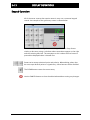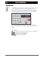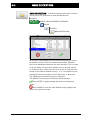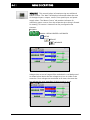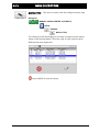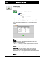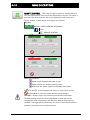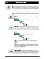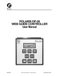
1
FIFE GUIDING SOLUTIONS FIFE-500-XL User Manual EN MI 2-267 1 B Medium Web Guiding System CONTENTS INTRODUCTION .................................................................................... 1-1 Copyright information ........................................................................................... 1-1 Language............................................................................................................... 1-1 Theory of operation ............................................................................................... 1-1 SAFETY INSTRUCTIONS .......................................................................... 2-1 Symbols used ........................................................................................................ 2-2 Basic safety information ........................................................................................ 2-3 Warnings ............................................................................................................... 2-5 DISPLAY DEFINITIONS ............................................................................ 3-1 Button Functions and Definitions ........................................................................... 3-3 Status Bar Definitions ............................................................................................ 3-5 Manual Menu Tree ................................................................................................. 3-7 Servo-Center Menu Tree........................................................................................ 3-9 Automatic Menu Tree .......................................................................................... 3-10 Security Strategy .................................................................................................. 3-11 Authorization Levels ...................................................................................... 3-11 Access Modes ................................................................................................ 3-12 Keypad Operation ................................................................................................ 3-13 MENU DESCRIPTIONS ............................................................................. 4-1 Security ................................................................................................................. 4-1 Logout ............................................................................................................. 4-1 Login ............................................................................................................... 4-1 Passwords ........................................................................................................ 4-2 Menu Protection............................................................................................... 4-3 Display .................................................................................................................. 4-4 Language ......................................................................................................... 4-4 Brightness........................................................................................................ 4-5 Rotate .............................................................................................................. 4-6 Calibrate Touch ............................................................................................... 4-7 OI Settings ....................................................................................................... 4-8 Service ................................................................................................................. 4-10 About ............................................................................................................ 4-10 Measure ......................................................................................................... 4-11 Control Outputs ............................................................................................. 4-13 Color Test ...................................................................................................... 4-14 Motor Type .................................................................................................... 4-15 Com Statistics ................................................................................................ 4-16 Remote Control ................................................................................................... 4-18 ASC ..................................................................................................................... 4-19 ASC Off .......................................................................................................... 4-19 ASC On .......................................................................................................... 4-19 www.maxcessintl.com FIFE-500-XL MI 2-267 1 B CONTENTS ASC Settings .................................................................................................. 4-19 Gain ..................................................................................................................... 4-22 SC Gain ................................................................................................................ 4-25 Sensor Setup ....................................................................................................... 4-26 Autosetup ............................................................................................................ 4-29 Guide Settings ..................................................................................................... 4-31 Control Options ................................................................................................... 4-32 Power On Mode ................................................................................................... 4-34 Backup ................................................................................................................ 4-35 Restore ................................................................................................................ 4-36 Hardlock .............................................................................................................. 4-37 Name ................................................................................................................... 4-38 Network ............................................................................................................... 4-39 Line Speed ........................................................................................................... 4-40 MCP-05 Option ................................................................................................... 4-43 MCP-05 Operation .............................................................................................. 4-46 DIGITAL INPUT/OUTPUT MATRIX ............................................................ 5-1 Digital Input Matrix ............................................................................................... 5-1 Digital Output Matrix ............................................................................................. 5-2 SYSTEM NOTES ..................................................................................... 6-1 TROUBLESHOOTING .............................................................................. 7-1 Fault Diagnostics and Rectification ........................................................................ 7-1 SERVICE AND REPLACEMENT PARTS ........................................................ 8-1 www.maxcessintl.com FIFE-500-XL MI 2-267 1 B 1-1 INTRODUCTION Introduction Copyright information All of the information herein is the exclusive proprietary property of Maxcess International, and is disclosed with the understanding that it will be retained in confidence and will neither be duplicated nor copied in whole or in part nor be used for any purpose other than for which disclosed. Language These are the original instructions, written in English. Theory of operation The FIFE-500-XL Web Guiding System is designed for use in industrial equipment that is involved with processing a moving web. It is typically installed in line with web travel to provide lateral steering of the web in critical areas such as winding, rewinding, or any important mid-stream process. It is not uncommon to find multiple web guides steering the same web at different locations of web travel. Guiding a web is accomplished by applying several concepts with each directed at a particular part of the task. The basic concepts are: Sense the lateral position of the web edge (sensors) Generate a correction signal proportional to the error (signal processor) Apply forces to the web to non-destructively move it to the desired location (motor-controlled mechanical pivoting rollers) Sensing Sensing the lateral position of the web edge can be done by a variety of sensing technologies with the most common being infrared or ultrasonic. The sensing technology employed in any given application is driven by the respective web properties in combination with the amount of sensor proportional band that is needed. For optically opaque webs, infrared sensors are common, but for webs that are highly transparent, ultrasonic methods are more successful. Infrared sensing Infrared sensors direct infrared light from a transmitter through the sensing gap to the opposing receiver. In this arrangement, web lateral position is determined by the amount of light that arrives at the receiver. Modulation techniques and infrared filtering is commonly used to combat interference from ambient light sources. www.maxcessintl.com FIFE-500-XL MI 2-267 1 B 1-2 INTRODUCTION Ultrasonic sensing Ultrasonic sensors work similar to infrared methods except they use high frequency sound waves instead of light. Correction signal The sensor information is provided to a signal processor that can provide many types of signal conditioning, including amplification, guide point offset compensation, etc. The final result, however, is simply a motor drive signal of the proper polarity to cause web movement to the desired web position. Additional provisions are present in the signal processor to control manual guide positioning, select from multiple sensor inputs, perform automatic guide centering, and remote control support. Web guiding The output of the signal processor is fed to a motor that is coupled to a set of pivoting rollers. In order to ensure enough friction exists between the moving web and the guide rollers, the web path and location of the guide rollers are designed to ensure a certain amount of surface area contact with the roller surface. Under these conditions, the pivoting roller set in combination with web movement over the rollers, provides the forces needed to control lateral web displacement. As a system, these concepts work together to sense the web lateral position and generate a motor drive signal of proper polarity to cause the web to move toward the desired location. This cycle is repeated continuously thus forming a closed loop control system to actively maintain the web at the desired position. www.maxcessintl.com FIFE-500-XL MI 2-267 1 B 2-1 1 SAFETY INSTRUCTIONS Safety Instructions Instructions for use To ensure safe and problem free installation of the web guiding system, the web guiding system must be properly transported and stored, professionally installed and placed in operation. Proper operation and maintenance will ensure a long service life of the device. Only persons who are acquainted with the installation, commissioning, operation and maintenance of the system and who possess the necessary qualifications for their activities may work on the web guiding system. Note: The safety information may not be comprehensive. Please note the following: The content of these operating instructions Any safety instructions on the device The machine manufacturer’s specifications All national, state, and local requirements for installation, accident prevention and environmental protection Information about safety instructions The safety instructions and symbols described in this section are used in these operating instructions. They are used to avoid possible dangers for users and to prevent material damage. SIGNAL WORD Source of danger and its results Avoiding dangers The signal word DANGER refers to the danger of death or serious bodily injuries. The signal word WARNING refers to the danger of moderate to severe bodily injuries. The signal word CAUTION refers to the danger of slight to moderate bodily injuries or material damage. The signal word NOTICE refers to the possibility of damage to equipment. www.maxcessintl.com FIFE-500-XL MI 2-267 1 B 2-2 Symbols used 2 SAFETY INSTRUCTIONS The following safety identification symbols are used in these operating instructions. WARNING/CAUTION – General danger or important note Reference to general hazards that may result in bodily injuries or damage to device or material. WARNING/CAUTION – Danger due to crushing Reference to danger of injury caused by crushing. WARNING/CAUTION – Danger due to cutting Reference to danger of injury caused by cutting. WARNING/CAUTION – Danger due to voltage, electric shock Reference to danger of injury caused by electric shock due to voltage. WARNING/CAUTION – Danger due to hot surfaces Reference to risk of injury caused by burning. www.maxcessintl.com FIFE-500-XL MI 2-267 1 B 2-3 3 SAFETY INSTRUCTIONS Basic safety Proper use information The web guiding system is intended to be used on machines or systems to guide a web of material. For indoor operation, see environmental specifications. Improper use Operation outside the technical specifications Operation in an Ex-area or intrinsically safe area Operation as a safety component. The web guiding system does not hold the web position if power fails. Outdoor operation Any other use than the proper use shall be deemed inappropriate Installation and commissioning Disconnect power from the FIFE-500-XL before connecting or disconnecting any cables. All cable connectors must be tightened sufficiently to provide the required connection for the cable shielding. Any web guiding system which is damaged must not be installed or put into operation. Only perform installation, maintenance or repair tasks on the web guiding system when the machine has been stopped and is secured from being turned on. Only perform installation, maintenance or repair tasks on the web guiding system when there is no electrical power in the system. The web guiding system must be securely mounted before being placed in operation. Only replacement parts obtained from Fife may be used. No modifications may be made to the web guiding system. Do not place electrical cables under mechanical strain. WARNING – Death or injury can result from static electric shocks. Moving webs of material can produce large static voltage potentials. Protect against electric shocks by installing a conductive connection between the terminal marked with the PE symbol on the power connector and the PE circuit of the building or machine. WARNING – The web guiding system contains rotating and moving parts which could cause injury due to crushing. Appropriate protective guards must be installed by the user according to his use of this product. www.maxcessintl.com FIFE-500-XL MI 2-267 1 B 2-4 4 SAFETY INSTRUCTIONS Basic safety information (continued) WARNING – Death or injury can result from unexpected movement. Protect against unexpected movement by removing electrical power from the web guiding system and the machine into which the web guiding system is being installed. WARNING – Danger of falling down or muscle or skeletal injury during installation. These web guiding systems, especially the larger designs, are heavy. Appropriate equipment is to be used and the safety rules of the company must be observed. Operation WARNING – The web guiding system contains rotating and moving parts which could cause injury due to crushing. Do not touch anything on or in the vicinity of the moving or rotating parts. Appropriate protective guards must be installed by the user according to his use of this product. Maintenance and Repair WARNING – Death or injury can result from unexpected movement. Protect against unexpected movement by removing electrical power from the web guiding system and the machine into which the web guiding system is installed. WARNING – Danger of injury from crushing. Maintenance and repair tasks on the web guiding system must be performed only when the machine has been stopped and has been secured from being turned on again. WARNING – Danger of falling down or muscle or skeletal injury during maintenance and repair. These web guiding systems, especially the larger designs, are heavy. Appropriate equipment is to be used and the safety rules of the company must be observed. Decommissioning The web guiding system must be disposed of in accordance with all the applicable national, state and local regulations. www.maxcessintl.com FIFE-500-XL MI 2-267 1 B 2-5 Warnings 5 SAFETY INSTRUCTIONS The FIFE-500-XL Web Guiding System may be remotely controlled via a digital port connection. As with any remotelycontrolled device, when remote control of the device is implemented, there is the possibility of movement of the guiding structure when remote commands are issued. Therefore, any time personnel are near the guiding structure, it is recommended that standard safeguards be taken to prevent injury. During servicing of the equipment, to prevent injury to personnel, it is recommended that standard Lockout/Tagout procedures be used. The FIFE-500-XL Operator Interface should not be used while the machine is running. If it is necessary for the operator to use the Operator Interface while the machine is running, precautions must be taken to protect the operator from injury due to moving material and machinery. This can be accomplished by either surrounding the Operator Interface with a safety screen, or by remote mounting the Operator Interface in a safe location. www.maxcessintl.com FIFE-500-XL MI 2-267 1 B 3-1 DISPLAY DEFINITIONS Display Definitions The FIFE-500-XL uses a QVGA Touchscreen for Operator command inputs and status displays. This Control Panel is divided into five sections of information for which brief descriptions follow. Refer to Figure 1 for the button locations in the standard, horizontal Control Panel. The vertical section on the left side contains the Operation Mode selection buttons (Automatic, Servo Center, and Manual) and indicates the current Operation Mode selection by displaying the corresponding button in a green color. (Other buttons are blue). The horizontal section at the top, above the line, contains the status bar which always contains the screen number. It may also indicate statuses, errors, and digital I/O. The middle section indicates the current Operation Mode, the selected sensor signal level in a bar graph, and the position of the system guide point. This section also contains buttons for Guidepoint Shift and Guidepoint Reset. The lower middle section contains the Left and Right Jog buttons. The vertical section on the right side contains the Sensor Selection and Setup buttons and indicates the current Sensor Mode selection by displaying the proper sensor symbol in the Sensor Select button. Figure 1. FIFE-500-XL CONTROL PANEL (0° AND 180° ROTATION) www.maxcessintl.com FIFE-500-XL MI 2-267 1 B 3-2 DISPLAY DEFINITIONS The Control Panel can also be configured in a vertical orientation. For the vertical orientation, the following display descriptions apply. Refer to Figure 2 for the button locations. The horizontal section along the top, above the line, contains the status bar which always contains the menu number. It may also indicate statuses, errors, and digital I/O. The horizontal section near the top, just below the line, contains the Operation Mode selection buttons (Automatic, Servo Center, and Manual) and indicates the current Operation Mode selection by displaying that button in a green color. The section just below the Operation Mode buttons, indicates the current Operation Mode, the selected sensor signal level in a bar graph, and the position of the system guide point. This section also contains the Guidepoint Shift buttons and the Guidepoint Reset button. The section below that, just above the Sensor Select and Setup buttons, contains the Left and Right Jog buttons. The horizontal section along the bottom contains the Sensor Selection and Setup buttons and indicates the current Sensor Mode selection by displaying the proper sensor symbol in the Sensor Select button. Figure 2. FIFE-500-XL CONTROL PANEL (90° AND 270° ROTATION) www.maxcessintl.com FIFE-500-XL MI 2-267 1 B 3-3 DISPLAY DEFINITIONS Button Functions and Definitions AUTOMATIC Initiates the Automatic mode. Correction is applied to the web by moving the guide in response to the output of the sensor(s) that have been selected. SERVO-CENTER Initiates the Servo-Center mode. The guide is centered in its travel in response to the output of the internal Servo-Center transducer. MANUAL Initiates the Manual mode. No correction is applied to the guide. SENSOR Use to select the sensor(s) to be used for monitoring the web position when the system is in Automatic mode. Sensor selection is allowed in Manual and Servo-Center modes only. SETUP Use to enter the Setup Menus for configuring and adjusting the guiding system. ARROWS Use these buttons to jog the guide. The direction of guide movement is configurable. GUIDE POINT CONTROL Use the two arrow buttons to adjust the System Guide Point while in Automatic Mode or Manual Mode. Use the center button to reset the System Guide Point to the default value, which is 50% of the sensor bandwidth. The slider control indicates the guide point position. The color of the guide point pointer is blue when the guide point is zero, yellow when a guide point shift is present and red when the guide point shift has reached either extreme. GUIDE POINT CAPTURE This optional button (which can be enabled from the “OI Settings” menu) sets the guide point of the active sensor mode to the current web location. This allows guiding to begin at the current web location when the Automatic mode is initiated. DRIVE SELECT This button will only appear in networked systems. When available, it displays a list of available drives in the network and allows the OI to be switched directly to any of them. DRIVE SELECT These buttons will only appear in networked systems. When available, they allow the operator interface to be connected to the previous or next sequential drive in the network. www.maxcessintl.com FIFE-500-XL MI 2-267 1 B 3-4 DISPLAY DEFINITIONS LINK DRIVES This optional button (which can be enabled from the “OI Settings” menu) will only appear in networked systems. When the “linked mode” is active (indicated by the green button appearance), Automatic, Manual, and Servo Center commands initiated from this Operator Interface are directed to all drives in the network simultaneously. BACK Use this menu navigation button to return to the previous menu level. HOME Use to return to the Operator Level screen. MENU ARROWS Use in the menu system to page forward or backward when multiple pages of menu choices are available. The arrows are disabled when no more choices are available in the respective direction. ACCEPT Use to save a changed value and return to the previous screen. REJECT Use to discard a changed value and return to the previous screen. www.maxcessintl.com FIFE-500-XL MI 2-267 1 B 3-5 DISPLAY DEFINITIONS Status Bar Definitions The status bar located horizontally across the top of the FIFE-500-XL Web Guide Operator Level screen remains visible at all times. The number on the left side of the status bar contains the numerical address of the connected motor controller and it should always be 1 (except in networked systems, where it will indicate the address of the currently selected drive). The number on the right side of the status bar indicates a hierarchical screen number. The first numerical value indicates the operation mode (1=Manual, 2=Servo-Center, 3=Automatic). The second alphabetic character indicates the sensor mode (A=S1, B=S2, C=S1-S2). This screen number uniquely identifies each screen of the FIFE-500-XL Web Guiding System. The status bar also displays various icons which are described below. OPERATION MODE One of these icons will appear to indicate the operation mode of the FIFE-500-XL Web Guiding System. These do not appear on the Operator Level screen since the mode buttons already indicate this information. These will only appear while in the setup screens. SENSOR SELECTION One of these icons will appear to indicate the currently selected sensor mode. These do not appear on the Operator Level screen since the SENSOR button already contains this information. MENU TIMEOUT The menu screens in the FIFE-500-XL Web Guiding System close automatically after 3 minutes of touch screen inactivity. The inactivity timeout option and the timeout value are configurable. The clock icons will appear during stages of the timeout process as the inactivity timer counts down. If a timeout occurs, the respective menu will abort any changes applied and return to the Operator Level screen. Some service-related screens are immune from the timeout option and are indicated by the presence of the orange clock icon. LOGIN AUTHORIZATION LEVEL When security has been configured, one of these icons will appear to indicate the authorization level of the current user. Level 1 has the least access while level 3 has the most. Security is disabled in the factory default configuration so these icons will not be displayed. All menu screens are accessible when security is disabled. READ ONLY MENU When security is enabled, options are available to make menus “read only”, allowing an operator to view the settings but not change them. This icon will appear when the active menu is a “read only” menu. www.maxcessintl.com FIFE-500-XL MI 2-267 1 B 3-6 DISPLAY DEFINITIONS DIGITAL INPUT COMMAND This icon appears when a valid digital input command is present. Depending on the command, some touch panel controls may be disabled during this time. A red arrow in the down direction indicates digital input influence is disabled. A red up arrow indicates the digital outputs are disabled. GUIDE POINT CHANGED This icon appears when a new System Guidepoint has been applied. This icon will appear on the status bar until the System Guidepoint remains unchanged for approximately 20 seconds. EXTERNAL LOCK This icon indicates the acceptance of the “External Lock” digital input command. Automatic guide movement is prohibited while in this state. ASC ON Automatic Sensor Control (ASC) is enabled for the current sensor mode. See the menu description for ASC for more information about ASC operation. ASC ACTIVE Automatic Sensor Control (ASC) is enabled and the ASC state has been triggered. Automatic guide movement is prohibited. See the menu description for ASC for more information about ASC operation. MOTOR BLOCKED This icon indicates the motor is stalled. COMMUNICATION ERROR This error icon indicates communication is not working between the operator interface and the motor controller. VOLTAGE ERROR This error icon appears when the input voltage, motor rail voltage, or internal 12 volt power is outside acceptable range. NETWORK ERROR This icon appears when the operator interface is unable to gain network control. LINKED MODE This icon appears when the “linked mode” is active. Linked mode is used in networked systems to send the Automatic, Manual, and Servo Center commands to all network devices simultaneously. MOTOR TYPE FAULT This icon appears when there is no motor type configured. COMMUNICATION FAULT This icon appears when a problem is detected with the communication signals. This can be caused by hardware or an addressing conflict in a networked system. LINE SPEED ZERO This icon appears when line speed control is enabled and the sensed line speed is zero. Guide correction is inhibited in Automatic mode under these conditions. MCP-05 SEEK If the MCP-05 option has been enabled, this icon will blink while a seek operation is in progress. www.maxcessintl.com FIFE-500-XL MI 2-267 1 B 3-7 DISPLAY DEFINITIONS Manual Menu Tree The menus that are available in the FIFE-500-XL Web Guiding System vary depending on the active operation mode. The following information provides a quick reference to summarize the menu tree for each mode. Each menu is described in more detail later in this document. 1X MANUAL SETUP 1X.1.1 SECURITY 1X.1.1.1 LOGOUT 1X.1.1.2 LOGIN 1X.1.1.3 PASSWORDS 1X.1.1.4 MENU PROTECTION 1X.1.2 DISPLAY 1X.1.2.1 LANGUAGE 1X.1.2.2 BRIGHTNESS 1X.1.2.3 ROTATE 1X.1.2.4 CALIBRATE TOUCH 1X.1.2.5 OI SETTINGS 1X.1.3 SERVICE 1X.1.3.1 ABOUT 1X.1.3.2 MEASURE 1X.1.3.3 CONTROL OUTPUTS 1X.1.3.4 COLOR TEST 1X.1.3.5 MOTOR TYPE 1X.1.3.6 COM STATISTICS 1X.1.4 REMOTE CONTROL 1X.1.5 ASC 1X.1.5.1 ASC OFF 1X.1.5.2 ASC ON 1X.1.5.3 ASC SETTINGS www.maxcessintl.com FIFE-500-XL MI 2-267 1 B 3-8 DISPLAY DEFINITIONS 1X.1.6 GAIN 1X.1.7 SENSOR SETUP 1X.1.8 AUTOSETUP Page forward/back 1X.2.1 GUIDE SETTINGS 1X.2.2 CONTROL OPTIONS 1X.2.3 POWER ON MODE 1X.2.4 BACKUP 1X.2.5 RESTORE 1X.2.6 HARDLOCK 1X.2.7 NAME 1X.2.8 NETWORK Page forward/back 1X.3.1 LINE SPEED 1X.3.2 MCP-05 OPTION www.maxcessintl.com FIFE-500-XL MI 2-267 1 B 3-9 DISPLAY DEFINITIONS Servo-Center Menu Tree 2X SERVO-CENTER SETUP 2X.1.1 SECURITY 2X.1.1.1 LOGOUT 2X.1.1.2 LOGIN 2X.1.1.3 PASSWORDS 2X.1.1.4 MENU PROTECTION 2X.1.2 DISPLAY 2X.1.2.1 LANGUAGE 2X.1.2.2 BRIGHTNESS 2X.1.2.3 ROTATE 2X.1.2.4 CALIBRATE TOUCH 2X.1.2.5 OI SETTINGS 2X.1.3 SERVICE 2X.1.3.1 ABOUT 2X.1.3.2 MEASURE 2X.1.3.3 CONTROL OUTPUTS 2X.1.3.4 COLOR TEST 2X.1.3.5 MOTOR TYPE 2X.1.3.6 COM STATISTICS 2X.1.4 REMOTE CONTROL 2X.1.5 ASC 2X.1.5.1 ASC OFF 2X.1.5.2 ASC ON 2X.1.5.3 ASC SETTINGS 2X.1.6 SC GAIN 2X.1.7 CONTROL OPTIONS www.maxcessintl.com FIFE-500-XL MI 2-267 1 B 3-10 DISPLAY DEFINITIONS Automatic Menu Tree 3X AUTOMATIC SETUP 3X.1.1 SECURITY 3X.1.1.1 LOGOUT 3X.1.1.2 LOGIN 3X.1.1.3 PASSWORDS 3X.1.1.4 MENU PROTECTION 3X.1.2 DISPLAY 3X.1.2.1 LANGUAGE 3X.1.2.2 BRIGHTNESS 3X.1.2.3 ROTATE 3X.1.2.4 CALIBRATE TOUCH 3X.1.2.5 OI SETTINGS 3X.1.3 SERVICE 3X.1.3.1 ABOUT 3X.1.3.2 MEASURE 3X.1.3.3 CONTROL OUTPUTS 3X.1.3.4 COLOR TEST 3X.1.3.5 MOTOR TYPE 3X.1.3.6 COM STATISTICS 3X.1.4 REMOTE CONTROL 3X.1.5 ASC 3X.1.5.1 ASC OFF 3X.1.5.2 ASC ON 3X.1.5.3 ASC SETTINGS 3X.1.6 GAIN 3X.1.7 CONTROL OPTIONS www.maxcessintl.com FIFE-500-XL MI 2-267 1 B 3-11 DISPLAY DEFINITIONS Security Strategy The operator interface can be configured with security features to prevent unauthorized changes to the various settings that can be changed from the menu system, such as gain, polarity, etc. Security features are disabled by default but are easily configured and enabled. Access to every menu is individually programmable for one of three authorization levels. The following text describes the customer-configurable security strategy. Authorization Levels Security features are designed around three authorization levels with three access modes for each level. When security is enabled, the current login authorization level is indicated by a “key” icon in the status bar with the authorization level next to it. Level 1 has the lowest privileges and level 3 has the highest. If security is not in use, these icons will not appear. The three authorization levels and their associated icons are described below. OPERATOR LEVEL 1 This level requires no password knowledge and is intended to have the most restrictions. PRIVILEGED OPERATOR/SUPERVISOR This level is intended for operators who are able to make some adjustments. ADMINISTRATOR The administrator normally has unrestricted access to all menus, but if desired, even this level can be configured for restricted access to any menu as long as it is not related to administrative activities. www.maxcessintl.com FIFE-500-XL MI 2-267 1 B 3-12 DISPLAY DEFINITIONS Access Modes The SETUP button on the Operator Level screen and each menu in the FIFE-500-XL Web Guiding System has programmable access modes for each of the three possible authorization levels. The button appearance of each menu item indicates which access mode is active for the current login authorization level. The possible button appearances are shown below using the GAIN button as an example. NO ACCESS The “lock” icon superimposed on a button indicates that access is not allowed from the current login authorization level. Pressing the button will prompt for numeric pass code entry and will only allow access if the entered code raises the login authorization level high enough to permit access. READ ONLY ACCESS The “magnifier” icon superimposed on a button indicates that the menu has read-only access from the current login authorization level. The user is allowed to view the settings but not change them. FULL ACCESS The button will appear with no access modifier when there are no restrictions for the menu. This is also the button appearance when security is disabled. www.maxcessintl.com FIFE-500-XL MI 2-267 1 B 3-13 DISPLAY DEFINITIONS Keypad Operation All of the menu screens that require numeric entry use a common keypad control. An example of the gain entry screen is shown below. New values are entered using the numeric keypad buttons. Entry format similar to data entry using a calculator where new values appear on the right and shift existing data left. The exception to this is when the first button is pressed the displayed value is cleared first. Some entries accept a decimal point and polarity. When editing values that do not accept decimal points or signed entry, these buttons will be disabled. The CLEAR button erases the current entry. Use the CANCEL button to close the edit window without saving any changes. www.maxcessintl.com FIFE-500-XL MI 2-267 1 B 3-14 DISPLAY DEFINITIONS Keypad Operation (continued) The ENTER button checks the value according to the maximum and minimum limits and applies the new value if it is within acceptable range. If the entered value is outside either of the applicable limits, the entered number and the violated limit are marked in red as shown in the example below. If this occurs, the CLEAR button may be used to erase the entry and try again, or the CANCEL button will cancel the editing operation and close the window. Other controls: Unit – Optionally shows the active unit of measurement for the edited value. Maximum – Shows the maximum allowed value. Minimum – Shows the minimum allowed value. Current Value – Shows the current setting. www.maxcessintl.com FIFE-500-XL MI 2-267 1 B 4-1 MENU DESCRIPTIONS Menu Descriptions SECURITY This submenu provides access to all security related menu items. They are each described below. The security submenu is available from all operation modes. LOGOUT Logout sets the authorization level to one if security is enabled. Navigation: MANUAL / SERVO-CENTER / AUTOMATIC SETUP SECURITY LOGOUT This button is ignored, if security is not enabled. LOGIN If security has been enabled, login prompts for numeric code entry. The authorization level is changed according to the entered code. Navigation: MANUAL / SERVO-CENTER / AUTOMATIC SETUP SECURITY LOGIN Enter the password and press the ENTER key. Press the CANCEL button to abort the login process. The following message appears if security is not enabled. www.maxcessintl.com FIFE-500-XL MI 2-267 1 B 4-2 MENU DESCRIPTIONS PASSWORDS This menu is intended for administration level use to assign passwords for level 2 and level 3 users. Other options configurable from this menu include overall security on/off control and automatic logout operation after a programmable time. Navigation: MANUAL / SERVO-CENTER / AUTOMATIC SETUP SECURITY PASSWORDS Enable Security – Turns security feature on when checked. Automatically logout after timeout – When security is enabled, this option logs out after the specified time. This returns the login level to 1. Touch the ‘seconds’ edit control to modify the timeout value. Access level 2 – The level 2 pass code. Touch the edit control to enter or modify the level 2 pass code and enter the new pass code when prompted. The same code must be entered twice for verification. Access level 3 – The level 3 (administrator) pass code. Touch the edit control to enter or modify the level 2 pass code and enter the new pass code when prompted. The same code must be entered twice for verification. Press ACCEPT to save changes made while in the menu. If Enable Security is checked but no level 3 pass code has been assigned, an error dialog will appear. This protection is present to prevent enabling security before having an administrative password in place. Press CANCEL to exit the menu without saving any changes. Note: Pass codes should be from 1 to 9 digits in length. www.maxcessintl.com FIFE-500-XL MI 2-267 1 B 4-3 MENU DESCRIPTIONS MENU PROTECTION This administration level menu is used to control the access protection for each individual menu. Navigation: MANUAL / SERVO-CENTER / AUTOMATIC SETUP SECURITY MENU PROTECTION Each menu is represented in the list control along with the access permission for each of the three authorization levels. Submenu entries are indented according to the menu hierarchy. The first item in the list (Setup) can be used to block access to all setup menus. To modify an entry, select the menu entry in the list, and press the button in the columns labeled as level 1, 2, or 3 as needed to cycle through the permission options of Full, Read only, or No access. The CLEAR button applies full access to all entries. The DEFAULT button presets the factory default settings. Press ACCEPT to apply changes and return to the previous screen. Press CANCEL to exit this menu without saving changes and return to the previous screen. www.maxcessintl.com FIFE-500-XL MI 2-267 1 B 4-4 MENU DESCRIPTIONS DISPLAY The display submenu provides access to the operator interface settings. The display submenu is available in all operation modes. LANGUAGE The FIFE-500-XL supports multiple languages. Use this selection to choose from the supported list of languages. Navigation: MANUAL / SERVO-CENTER / AUTOMATIC SETUP DISPLAY LANGUAGE Use the page arrows to move forward or backward to see more choices. Select the desired language and press ACCEPT to save. The screen will return to the Operator Level screen. Press CANCEL to exit without saving changes and return to the previous screen. www.maxcessintl.com FIFE-500-XL MI 2-267 1 B 4-5 MENU DESCRIPTIONS BRIGHTNESS Adjusts the LCD backlight intensity. Navigation: MANUAL / SERVO-CENTER / AUTOMATIC SETUP DISPLAY BRIGHTNESS Press or hold the arrow buttons for fine control of the screen brightness or use the slider handle for quick movement. Press this button to set the brightness level to 50%. Press ACCEPT to save new brightness setting and return to the previous screen. Press CANCEL to return to the previous screen without saving changes. www.maxcessintl.com FIFE-500-XL MI 2-267 1 B 4-6 MENU DESCRIPTIONS ROTATE The FIFE-500-XL supports four rotation orientations of the operator interface. Choose from 0°, 90°, 180°, 270° settings. Navigation: MANUAL / SERVO-CENTER / AUTOMATIC SETUP DISPLAY ROTATE Select the desired screen rotation and press the ACCEPT button to save. The screen will go blank for a moment and restart in the new orientation. Press CANCEL to return to the previous screen without saving changes. www.maxcessintl.com FIFE-500-XL MI 2-267 1 B 4-7 MENU DESCRIPTIONS CALIBRATE TOUCH Use this menu to recalibrate the touch panel sensitivity. This is only necessary if button reactions appear to be out of sync with the displayed button locations. The screen will go blank for a moment followed by prompts to touch the screen in two locations. Note: A stylus is recommended to improve the accuracy of calibration. Navigation MANUAL / SERVO-CENTER / AUTOMATIC SETUP DISPLAY CALIBRATE TOUCH www.maxcessintl.com FIFE-500-XL MI 2-267 1 B 4-8 MENU DESCRIPTIONS OI SETTINGS Provides access to various operator interface settings. Navigation: MANUAL / SERVO-CENTER / AUTOMATIC SETUP DISPLAY OI SETTINGS Enable menu timeouts – Check this box to force menus to close after a specified number of seconds. To adjust the timeout value, press the “seconds” control and enter the desired value. Some menus are immune from the timeout option. Menus that are immune from timeout will show this icon in the status bar (only when timeouts are enabled). OI Address – Address of the OI in a networked system. Any value between 1 and 31 is valid. The default value of 30 is recommended in a non-networked system. OI Termination – Should always be checked in a non-networked system. In a networked system, should be checked if the OI is at the end of the line and unchecked otherwise. Refer to the supplementary user instructions, "Fife FIFE-500-XL: Networking of Web Guiding Systems" (MI 1-919) for details. Bargraph update speed – This slider controls the update speed of the sensor signal bargraph on the Operator Level screen. Default Connection – To specify which device this OI should connect to when power is applied. Specified device – The Operator Interface will always connect to the drive address specified in the associated edit control. First device found – The Operator Interface will connect to the first drive it finds in the network. www.maxcessintl.com FIFE-500-XL MI 2-267 1 B 4-9 MENU DESCRIPTIONS Last connected device – Connect to the same drive the Operator Interface was connected to when powered off. Always show sensor – Causes the bar graph on the main screen to show sensor value for the current sensor mode instead of the Servo Center transducer signal. The default setting (unchecked) displays the Servo Center sensor value while in the Servo Center mode. Enable GP capture – Enables the appearance of an additional button in the guide point control area of the Operator Level screen. The GP capture button (available only in Manual and Servo Center modes) sets the guide point of the active sensor mode to match the current location of the web. This allows guiding to begin at the current web location when the Automatic mode is initiated. Enable link option – For use in networked systems. Checking this option enables an additional button in the drive select area of the Operator Level screen. When the link option is enabled, and the link mode is active, Auto, Manual, and Servo Center commands initiated from this Operator Interface are directed to all drives in the network allowing modes of all network devices to be synchronized. Press ACCEPT to save changes and return to the previous screen. Press CANCEL to close this menu without saving changes. www.maxcessintl.com FIFE-500-XL MI 2-267 1 B 4-10 MENU DESCRIPTIONS SERVICE The service submenu provides access to maintenance screens. The service submenu is available in all operation modes. ABOUT This screen provides firmware version information. Navigation: MANUAL / SERVO-CENTER / AUTOMATIC SETUP SERVICE ABOUT www.maxcessintl.com FIFE-500-XL MI 2-267 1 B 4-11 MENU DESCRIPTIONS MEASURE This menu displays information using two additional tabbed screens. The “Main” tab displays information about the state of the digital inputs, outputs, sensors, line speed input, and power supply values. The “Motor Current” tab provides indicators for monitoring motor current. Press the respective tab to bring it forward for viewing. This menu is immune from any configured menu timeouts. Navigation: MANUAL / SERVO-CENTER / AUTOMATIC SETUP SERVICE MEASURE Voltages that are out of range will be marked with a red background as shown below. Notice that the voltage error icon is visible on the status bar. Since voltages are monitored at all times, the status bar can indicate this error regardless of which screen is active. www.maxcessintl.com FIFE-500-XL MI 2-267 1 B 4-12 MENU DESCRIPTIONS The “Motor Current” tab contains an analog/digital ammeter indicating the motor current and polarity. A graph is also present to display history of the recent motor current activity. Press ACCEPT to close this menu and return to the previous screen. www.maxcessintl.com FIFE-500-XL MI 2-267 1 B 4-13 MENU DESCRIPTIONS CONTROL OUTPUTS This screen contains buttons to test the output signals. Each signal can be individually set or cleared. Changes made in this screen are temporary, so the outputs resume their normal operation when exiting this screen. This menu is immune from menu timeouts. Navigation: MANUAL / SERVO-CENTER / AUTOMATIC SETUP SERVICE CONTROL OUTPUTS Press OK to close this window. Press ACCEPT to return to the previous screen. A reminder message will be displayed indicating the digital outputs will resume their normal operation. WARNING – Death or injury can result from unexpected movement. The web guiding system has four independent outputs that can be connected to other components into which the web guiding system is installed. Take appropriate precautions to ensure no one may be killed or injured by activation of any of these outputs. www.maxcessintl.com FIFE-500-XL MI 2-267 1 B 4-14 MENU DESCRIPTIONS COLOR TEST This menu is used to verify display screen control signals by providing configurable color gradient screens. Navigation: MANUAL / SERVO-CENTER / AUTOMATIC SETUP SERVICE COLOR TEST The six slider controls can be used to vary the red, green, and blue brightness for the left and right sides of the screen. (If the Vertical mode is selected, the sliders control the top and bottom colors respectively.) Test The Test button cycles through a sequence of gradient settings which would most likely identify hardware related signal issues. Horz/Vert This control selects the gradient direction (horizontal or vertical). The red, green, and blue buttons on each side cycle through an 8-bit binary sequence selected to drive each signal separately in the color circuitry. Small changes present in this sequences typically produce no visually discernable screen change and are only used in conjunction with more detailed service activities. Color values vary from 0 to 255, with a value of zero representing no color and 255 representing maximum color. To specify a color value, touch the respective red, green or blue edit control and enter the desired value. Press the ACCEPT button to return to the previous screen. www.maxcessintl.com FIFE-500-XL MI 2-267 1 B 4-15 MENU DESCRIPTIONS MOTOR TYPE This menu is used to view the configured motor type. Navigation: MANUAL / SERVO-CENTER / AUTOMATIC SETUP SERVICE MOTOR TYPE The resulting screen will display the currently configured motor type as shown in the example below. The motor type for your system may be different than that shown here. Press CANCEL to close this menu. www.maxcessintl.com FIFE-500-XL MI 2-267 1 B 4-16 MENU DESCRIPTIONS COM STATISTICS This menu is used to view the communication statistics maintained by each device. Navigation: MANUAL / SERVO-CENTER / AUTOMATIC SETUP SERVICE COM STATISTICS The Operator Interface communicates with one or more motors using a serial communication bus. The bus topology is a half-duplex multi-drop configuration. The COM STATISTICS screen shows a live update of the running network communication statistics as shown in the following example. Sent – Indicates the total number of packets sent. Received – Indicates the total packets received. Rcv-Mine – Indicates the total number of packets received that were addressed to the respective device. Rcv-Not mine – The number of packets received (and discarded) because they were not addressed to the respective device. Buffer full – Indicates the number of packets discarded because the devices receive buffers were full. Bad checksum – Each packet received is verified using a checksum algorithm. Packets that fail the checksum validation are discarded. Checksums can occur at a low frequency under normal circumstances due to noise, power cycles, etc. A rapidly increasing checksum count is an indication of a communication problem. No Reply – Counts the occurrences where the Operator Interface expected www.maxcessintl.com FIFE-500-XL MI 2-267 1 B 4-17 MENU DESCRIPTIONS a reply but did not receive one. These errors occur occasionally under normal circumstances, but like the checksum fault, should not increase rapidly. Token Cycles – This counter will only increase in systems containing multiple Operator Interfaces. It signifies the activity conducted by multiple Operator Interface devices to share access to the communication bus. Press the ACCEPT button to return to the previous screen. www.maxcessintl.com FIFE-500-XL MI 2-267 1 B 4-18 MENU DESCRIPTIONS REMOTE CONTROL This menu is used to enable or disable influence from the digital inputs and turn off the digital output signals. This menu is immune from menu timeouts. An icon is displayed on the status bar if inputs, outputs, or both inputs and outputs are disabled. Navigation: MANUAL / SERVO-CENTER / AUTOMATIC SETUP REMOTE CONTROL Status bar indicators: Digital inputs disabled (red down arrow). Digital outputs are disabled (red up arrow). Both input and output signals are disabled (red arrows). Press ACCEPT to save changes and return to the previous screen. Press CANCEL to close this menu without saving changes. WARNING – Death or injury can result from unexpected movement. The web guiding system has four independent outputs that can be connected to other components into which the web guiding system is installed. Take appropriate precautions to ensure no one may be killed or injured by activation of any of these outputs. www.maxcessintl.com FIFE-500-XL MI 2-267 1 B 4-19 MENU DESCRIPTIONS ASC Automatic Sensor Control (ASC) can be used under certain conditions where it is desirable to ignore sudden sensor input changes. A typical use for ASC is to ignore a “tearout” in the web preventing the guide from reacting to the subsequent large sensor signal change. ASC can be configured and enabled separately for each sensor mode. To prevent unintended ASC activation, it must be enabled for each sensor mode that is needed using the ASC SETTINGS menu before the ASC ON button will work. ASC OFF Disable ASC operation for the selected sensor mode. This button has no effect if ASC is already off or has not been configured. Navigation: MANUAL / SERVO-CENTER / AUTOMATIC SETUP ASC ASC OFF ASC ON ASC ON enables ASC processing, if ASC control has been enabled in the configuration screen for the active sensor mode. Each sensor mode can be individually configured with different ASC settings. The availability of ASC for each sensor mode is among the configurable settings. Navigation: MANUAL / SERVO-CENTER / AUTOMATIC SETUP ASC ASC ON This icon will be displayed in the status bar when ASC is enabled. The ASC icon will change to this when ASC is enabled and the configured ASC threshold has been triggered. When ASC is enabled, this icon works in manual mode also which provides an easy way to view the ASC trigger thresholds. Note: ASC must be enabled for the active sensor mode before the ASC ON function will work. ASC SETTINGS This menu controls all programmable aspects of ASC operation for each sensor mode. The first three tabs have identical sets of controls for each sensor mode. The last tab contains polarity controls to set the polarity used for each sensor signal during ASC www.maxcessintl.com FIFE-500-XL MI 2-267 1 B 4-20 MENU DESCRIPTIONS processing. Navigation: MANUAL / SERVO-CENTER / AUTOMATIC SETUP ASC ASC SETTINGS Touch the tab controls at the top as needed to switch to the desired page before making changes. ASC State The ASC State button enables or disabled the availability of ASC use for the selected sensor mode. The LED displayed on the button indicates the present state. Press the button to toggle the ASC availability for this sensor mode on or off. Source Selects the sensor that is monitored for ASC thresholds. Typically this is the same sensor used for guiding but in some applications it could be desirable to monitor a different input. Source input choices include the sensor signal S1, S2, S1+S2, or S1S2. Mode The mode setting controls how the source signal threshold is processed. These modes are used configure ASC operation for specific application requirements. There are 6 modes available: Above + Signal is greater than the positive threshold. The negative threshold is not used. Below – Signal is less than the negative threshold. The positive threshold is not used. www.maxcessintl.com Outside Signal is less than the negative threshold +/- or greater than the positive threshold. FIFE-500-XL MI 2-267 1 B 4-21 MENU DESCRIPTIONS Below + Signal is less than the positive threshold. The negative threshold is not used. Above – Signal is greater than the negative threshold. The positive threshold is not used. Inside +/- Signal is greater than the negative threshold AND less than the positive threshold. ASC Threshold 2 (Neg) The ASC signal negative threshold. Touch the threshold value to open an edit screen to change it. ASC Threshold 1 (Pos) The ASC signal positive threshold. Touch the threshold value to open an edit screen to change it. Press ACCEPT to save changes and return to the previous screen. Press CANCEL to exit without saving changes and return to the previous screen. www.maxcessintl.com FIFE-500-XL MI 2-267 1 B 4-22 MENU DESCRIPTIONS GAIN The gain menu is used to view or set the system gain for the active sensor mode. Navigation: MANUAL / AUTOMATIC SETUP GAIN If the gain screen is accessed while the system is in Automatic mode, it will appear as shown below. Use the smaller arrows buttons to decrease or increase the system gain, or for fast gain changes use the slider control. The gain value is applied as soon as it is changed while in this menu, so the effects of gain changes can be observed if the system is in Automatic mode. The graph area shows the amplified output of the active sensor signal to provide feedback about guide movement as the gain is changed. Press ACCEPT to save changes and return to the previous screen. Press CANCEL to exit without saving changes and return to the previous screen. If the gain has been changed, it will be restored to its previous value. If the system is in Manual mode, the Gain screen will have an additional button (as shown below) to allow the auto setup function to be initiated from this screen, if desired. www.maxcessintl.com FIFE-500-XL MI 2-267 1 B 4-23 MENU DESCRIPTIONS When the gain menu is accessed from Manual mode, the AUTOSETUP button will be shown in one of the following two states, depending on the sensor signal level of the active sensor mode: Auto setup is available: The Auto setup is NOT available: system is in Manual mode The system is in Manual mode and the active sensor signal is but the sensor signal is not within the allowable range. within the allowable range. If the Auto setup button is not available, use the larger arrow buttons to jog the guide in either direction, until the sensor signal is within the allowable range and the Auto setup button is available. Press AUTOSETUP to initiate the auto setup cycle. The guide will move a short distance and the system gain value will be automatically set. The screen will display “Please wait” during this operation as shown in the example below. Press ACCEPT to save changes and return to the previous screen. Press CANCEL to exit without saving changes and return to the previous www.maxcessintl.com FIFE-500-XL MI 2-267 1 B 4-24 MENU DESCRIPTIONS screen. If the gain has been changed, it will be restored to its previous value. WARNING – Death or injury can result from unexpected movement. Auto setup operation causes guide movement. Take appropriate precautions to ensure no one is in the vicinity of the guide path of travel. www.maxcessintl.com FIFE-500-XL MI 2-267 1 B 4-25 MENU DESCRIPTIONS SC GAIN The Servo-center gain menu is used to view or set the gain for servo-center operation. Navigation: SERVO-CENTER SETUP SC GAIN The larger arrow buttons may be used to jog the guide in either direction, if desired. Use the smaller arrows buttons to decrease or increase the system gain or for fast gain changes, use the slider control. The gain value is applied as soon as it is changed while in this menu, so the effects of the servo-center gain changes can be observed. The graph area shows the amplified output of the servo-center transducer to provide feedback about guide movement as the gain is changed. Press ACCEPT to save changes and return to the previous screen. Press CANCEL to exit without saving changes and return to the previous screen. If the servo-center gain has been changed, it will be restored to its previous value. www.maxcessintl.com FIFE-500-XL MI 2-267 1 B 4-26 MENU DESCRIPTIONS SENSOR SETUP The factory sensor settings are for webs that are 100% opaque using the installed sensors. The sensor setup menu is used to calibrate the FIFE-500-XL Web Guiding System to maximize sensor signal sensitivity when used with webs that are not totally opaque. This procedure involves teaching the FIFE-500-XL Web Guiding System using a sample of the web material. Navigation: MANUAL SETUP SENSOR SETUP The FIFE-500-XL Web Guiding System stores separate calibration data for the S1 and S2 sensor inputs so the procedure should be done on each sensor input that will be used. The FIFE-500-XL Web Guiding System can store/recall up to four sets of calibration settings for S1 and S2 supporting the possibility to store and quickly recall sensor settings for four different web opacities. Button Descriptions: .. CALIBRATION SET These buttons select one of four sets of calibration values. Only one calibration set may be active at any given time with the active set indicated by the green LED on the button face. Set 1 is active by default. Touch the button for the desired set to make it active. Note: This change takes effect immediately while in this menu but will only become permanent if the ACCEPT button is pressed to save it. Note: If calibration set 2, 3, or 4 is in use, the sensor button on the Operator Level screen will reflect this by displaying a 2, 3, or 4 as shown here. When calibration set 1 is active, the sensor button on the Operator Level screen will not display a number. www.maxcessintl.com FIFE-500-XL MI 2-267 1 B 4-27 MENU DESCRIPTIONS The arrow buttons are used to jog the guide in either direction. This can be used to move the web in and out of the sensor during the calibration process. Use the sensor select button to select the sensor input channel before calibration. Pressing this button alternates between the S1 and S2 sensor input channels. Press ACCEPT to save the results of the last sensor calibration and return to the previous screen. This button is also required to save the results of selecting a different calibration set. Press CANCEL to exit without saving the results of the last calibration, and return to the previous screen. Any changes to the sensor calibration set is restored to its previous setting. Calibration Procedure: .. Select which set of calibration values will be used. Select S1 or S2 sensor input. Press the START CALIBRATION button. The bar graph indicator will be rescaled to show the full signal range of –20mA to +20mA on the selected sensor input. The sensor current will also be displayed under the bar graph as shown is the example screen below. Move the web material completely out of the sensor field of view and press the CALIBRATE S1 UNCOVER button. Move the web material into the sensor field of view until the entire proportional band of the sensor is covered, and press the CALIBRATE S1 COVER button. If the calibration was successful, the following message will appear. www.maxcessintl.com FIFE-500-XL MI 2-267 1 B 4-28 MENU DESCRIPTIONS Press OK to close this window. If other calibrations (ie: the opposite sensor channel) need to be done, proceed with selecting it and repeat the calibration process. Otherwise, press ACCEPT to save these changes and return to the previous screen. Note: If a different calibration set is chosen after a successful calibration has been completed, it will be permanently saved before switching to the new calibration set. In this case, exiting this menu with the CANCEL button will not restore this calibration to its previous setting. If the sensor signal difference between the uncovered and covered states is too low, the web opacity is beyond calibration compensation and the message shown below will be displayed. Press OK to close this window. www.maxcessintl.com FIFE-500-XL MI 2-267 1 B 4-29 MENU DESCRIPTIONS AUTOSETUP The FIFE-500-XL Web Guiding System gain and polarity can be set manually as described in other areas of this manual. Using this menu however, the system gain and polarity can be determined automatically. Navigation: MANUAL SELECT SENSOR MODE SETUP AUTOSETUP Note: The auto setup procedure should be done with the web at a standstill. Auto setup is performed using the sensor mode that has been selected from the Operator Level screen. Before auto setup can begin, the web must be within the selected sensor field of view. The bar graph indicator shows the acceptable limits for the sensor signal and the AUTOSETUP button will remain disabled until the correct conditions are present. Use the jog buttons to position the web edge near the center of the sensor proportional band as shown below. Press the AUTOSETUP button to start. The guide will move a short distance as it completes the auto setup process. Successful completion is indicated by www.maxcessintl.com FIFE-500-XL MI 2-267 1 B 4-30 MENU DESCRIPTIONS the message shown below. Press OK to close this window. Press ACCEPT to return to the previous screen. The gain and polarity settings are stored automatically when auto setup completes. The gain and polarity settings are stored automatically when auto setup completes. Pressing the CANCEL button does not restore previous gain and polarity settings. WARNING – Death or injury can result from unexpected movement. Auto setup operation causes guide movement. Take appropriate precautions to ensure no one is in the vicinity of the guide path of travel. Note: For most installations, the Auto Setup routine sets the system gain at the proper level for good guiding performance. However, in some applications, for optimum guiding performance, it may be desirable to adjust the system gain, manually. Refer to “Gain” in section “Menu Descriptions” in this document. www.maxcessintl.com FIFE-500-XL MI 2-267 1 B 4-31 MENU DESCRIPTIONS GUIDE SETTINGS The guide settings screen provides controls to set the gain, polarity and dead band for all modes of operation. The jog polarity is also located on this screen. Navigation: MANUAL SETUP Page forward GUIDE SETTINGS . Polarity – The polarity buttons display the current polarity settings active for servo-center, guiding (each sensor mode), and jog operations. Using these controls polarity can be set manually. To change polarity, touch the desired polarity button to toggle between positive and negative settings. The auto setup procedure for each sensor mode configures polarity automatically so changes to the sensor mode polarities are typically not needed. Polarity changes are used to correct the situation if guide correction moves in the wrong direction. Jog polarity controls the direction of guide movement when the jog buttons are pressed. Gain – The gain controls display the gain settings for each mode of operation. The gain values are set automatically if the auto setup procedure is used. This screen provides controls to support manual gain tuning. To edit a gain setting, touch the desired gain value to open an edit window. An example edit window is shown on page 3-13. Dead band – The dead band value provides a configurable zone around the system guide point where no guiding correction occurs. A dead band setting of zero provides the most accurate guiding but in some applications where webs have ragged edges, dead band can be used to prevent guide reactions to these conditions. To edit a dead band setting, touch the desired dead band value and enter the new value in the displayed edit window. Press ACCEPT to save any changes made. Press CANCEL to exit without saving any changes. www.maxcessintl.com FIFE-500-XL MI 2-267 1 B 4-32 MENU DESCRIPTIONS CONTROL OPTIONS This menu provides the controls used to limit operation modes, sensor modes, and system guide point shift controls on the Operator Level screen. Navigation: MANUAL SETUP Page forward CONTROL OPTIONS Mode Enable – These checkboxes enable or disable use of automatic, servocenter, and manual operation modes. A “checked” box indicates the mode is available. When a mode is disabled, its corresponding button on the Operator Level screen is removed. At least one mode must remain enabled at all times. The menu will not permit saving a configuration with all checkboxes cleared. Jog Enable – These three checkboxes enable or disable jog operations in automatic, servo-center, and manual operation modes. A “checked” box indicates jogs are permitted. When jogs are disabled, the jog buttons on the Operator Level screen are unavailable. GP Enable – These checkboxes enable or disable the system guide point controls on the Operator Level screen in automatic, servo-center, and manual operation modes. A “checked” box indicates guide point controls are enabled. When disabled, the guide point controls on the Operator Level screen will be unavailable. This control does not affect guide point control from the digital inputs. (continued) www.maxcessintl.com FIFE-500-XL MI 2-267 1 B 4-33 MENU DESCRIPTIONS Sensor Enable – These controls configure which sensor modes can be selected using the SENSOR button on the Operator Level screen. The menu will not permit saving a configuration with all sensor modes disabled. Sensor Type –Used to select the desired icon appearance for sensor modes. The default setting uses a standard “C” style sensor appearance, but “line” sensors can be specified when applicable. Note: When line sensor icons are selected, the center guiding mode consisting of S1-S2 is disabled since it has no purpose in line guiding applications. Press ACCEPT to save changes made to this screen. Press CANCEL to exit without saving any changes. www.maxcessintl.com FIFE-500-XL MI 2-267 1 B 4-34 MENU DESCRIPTIONS POWER ON MODE This menu controls the Power On mode for the FIFE- 500-XL Web Guiding System. Default operation returns to the mode that was active when power was removed, however, configuration choices in this screen allow any mode to be selected as the Power On mode. Navigation: MANUAL SETUP Page forward POWER ON MODE Default – The default button selects the factory setting which is “Last mode used”. Power cycles – shows the number of power cycles the system has recorded. Press ACCEPT to save changes and return to the previous screen. Press CANCEL to close this screen and return to the previous screen without saving any changes. WARNING – Death or injury can result from unexpected movement. Selecting Automatic or Servo-Center modes for power up options can cause guide movement when power is applied. Take appropriate precautions to ensure no one is in the vicinity of the guide path of travel when power is applied to the web guiding system. www.maxcessintl.com FIFE-500-XL MI 2-267 1 B 4-35 MENU DESCRIPTIONS BACKUP Backup is used to make a copy of all configurable settings. These settings can be recalled using the RESTORE menu. Navigation: MANUAL SETUP Page forward BACKUP If a backup already exists, the system will ask for confirmation before replacing it. The screen below will be shown after the backup completes. Press the OK button to continue and return to the previous menu screen. Press OK to close this window. www.maxcessintl.com FIFE-500-XL MI 2-267 1 B 4-36 MENU DESCRIPTIONS RESTORE The restore function reloads all configurable options from a backup image if available. Navigation: MANUAL SETUP Page forward RESTORE If no backup image is present or it is corrupted, the following message will appear. Restore is not possible in this case. Press OK to close this window. Note: Restore reloads all user-configurable settings such as gains, polarities, etc. In order to prevent unintended password modification, restore does not replace active passwords from the backup image. www.maxcessintl.com FIFE-500-XL MI 2-267 1 B 4-37 MENU DESCRIPTIONS HARDLOCK Hard lock modifies actuator reaction while in manual mode. Normal manual posture removes all motor drive signals. In some applications, forces due to gravity or web tension can cause unwanted actuator movement when the motor is not driven. The hard lock option changes manual operation so actuator position is actively maintained to prevent movement from outside forces while in manual mode. Hard lock, if enabled is applied in all cases where manual posture is active such as when external lock from the digital inputs is active. Navigation: MANUAL SETUP Page forward HARDLOCK Enable Hardlock – Check this box to turn the hardlock feature on. Hardlock Polarity – Sets the hardlock correction polarity. Hardlock Gain – Sets the hardlock control loop gain. This can be changed with the slider control or with the arrow buttons for finer control. Press ACCEPT to save changes made to this screen. Press CANCEL to exit without saving any changes. www.maxcessintl.com FIFE-500-XL MI 2-267 1 B 4-38 MENU DESCRIPTIONS NAME Use the name menu to enter a drive name. The specified name can be 15 characters or less and is displayed on the Operator Level screen. This can be useful in a networked environment to identify the connected drive. Navigation: MANUAL SETUP Page forward NAME Enter up to 15 characters to describe the drive. Edit functions include: Del – Delete characters to the right of the cursor. Back – Backspace function deletes characters to the left of the cursor. The cursor can be moved by touching the desired position in the edit control. Press ACCEPT to save changes. Press CANCEL to exit without saving any changes. www.maxcessintl.com FIFE-500-XL MI 2-267 1 B 4-39 MENU DESCRIPTIONS NETWORK This menu is used for network administration. It is used when commissioning a network or replacing a device in the network. All devices in the network can be configured from any Operator Interface using this menu. Navigation: MANUAL SETUP Page forward NETWORK The initial screen shows a list of all devices present in the network. Select a device to be presented with configuration options for it. Device address – Used to assign a new address to the device. Name – This control only appears when configuring a drive. Use it to specify the drive name which will appear on the Operator Level screen when connected to this drive. Termination - If the device supports configurable termination, an additional checkbox will be present to support its configuration. Termination should www.maxcessintl.com FIFE-500-XL MI 2-267 1 B 4-40 MENU DESCRIPTIONS only be enabled on devices connected to the network ends. In a single Operator Interface and single drive configuration, both devices should have termination enabled. Note: When assigning network addresses, it is recommended to start drive addresses at 2 or higher. Leaving address 1 vacant facilitates replacing or adding a new drive. Since the default drive address is 1, it will initially appear at this address where it can be easily reassigned. Press ACCEPT to save changes. Press CANCEL to exit without saving any changes. LINE SPEED This menu is used to calibrate the line speed input signal and configure the line speed option. Navigation: MANUAL SETUP Page forward Page forward LINE SPEED Line speed control is used to automatically increase or decrease guide correction speed according to web travel speed. The guide correction speed influence applies only in the Automatic mode. The line speed input accepts a 0mA to 20mA signal representing the process line speed. www.maxcessintl.com FIFE-500-XL MI 2-267 1 B 4-41 MENU DESCRIPTIONS Maximum Speed bar graph – This bar graph shows the current state of the calibrated line speed input. The calibrated line speed input signal range is defined by the translucent green arc on the face of the Line speed input meter. Line speed input (gauge) – The analog line speed meter shows the live value of the 0-20mA line speed input. The calibrated range is also shown by the translucent green arc which appears on the meter face. Minimum Limit – This control accepts entry of a value between 0% and 100% to specify a minimum value for the line speed signal. The calibrated line speed value is prevented from dropping below the specified limit regardless of the actual line speed input. This is used to set a minimum correction speed to be applied even when the line speed drops below the specified percentage. Calibrating the line speed input Before using the line speed control feature, the line speed input should be calibrated to match the line speed input signal. During calibration, the minimum line speed signal is applied followed by the maximum line speed signal. When speed gain control is enabled, these minimum and maximum line speeds then correlate to minimum and maximum guide correction speed. Line speed calibration operates correctly regardless of line speed input polarity. For example, a Minimum Speed producing 10mA with a corresponding Maximum Speed producing 2mA is acceptable. In all cases, the Minimum Speed must be presented first. Start Calibration – Press this button to start the line speed input calibration process. In order to complete calibration, the line speed input will need to be presented at the minimum line speed followed by the maximum speed. Set Minimum Speed – Press this button after applying the minimum line speed signal. Set Maximum Speed – Press this button after applying the maximum line speed signal. A dialog box will appear after this step to confirm saving the new calibration values. Press ‘Yes’ to confirm, or press ‘No’ to abort saving the new calibration values. After new calibration values are saved, the calibrated range indicator (translucent arc) on the line speed input meter is updated to reflect the changes. Enable speed gain control – Check this box to allow the line speed input to control guide correction speed. A calibration of the line speed input is www.maxcessintl.com FIFE-500-XL MI 2-267 1 B 4-42 MENU DESCRIPTIONS recommended to ensure correct operation of this feature. Disabling this feature only disables line speed influence on guide correction. It does not erase any stored calibration parameters. Press ACCEPT to save changes. Press CANCEL to exit without saving any changes. www.maxcessintl.com FIFE-500-XL MI 2-267 1 B 4-43 MENU DESCRIPTIONS MCP-05 This menu is used to enable and configure the optional MCP-05 sensor positioning option. Navigation: MANUAL SETUP Page forward Page forward MCP-05 OPTION Enable MCP-05 – MCP-05 seek and manual control options are enabled when this control is checked. Show manual controls – Enables the appearance of a new button on the Operator Level screen that leads directly to the MCP-05 manual control screen. The MCP-05 manual control button is shown below. Propagate alarms – Control for the external MCP-05 device consumes two alarm signals. Enabling this option causes the state of the consumed alarm signals (selected by Control Sources) to be sent to the MCP-05 alarm outputs. These signals function normally on the MCP-05 outputs with the following exceptions: They are delayed by up to 500mS. They do not function during MCP-05 manual control or seek operations. During this time, they maintain their previous state. www.maxcessintl.com FIFE-500-XL MI 2-267 1 B 4-44 MENU DESCRIPTIONS Re-seek on ASC – Checking this option will cause the MCP-05 sensor positioner to re-seek to obtain the web location each time the ASC (Automatic Sensor Control) signal triggers. This can be useful in centerguiding applications to accommodate web width changes. Seek timeout – An optional time value (in seconds) to cancel seek operations. If the seek operation does not find the web within the specified time, the systems enters the Servo Center state and the sensor(s) retract. Specify a value of zero to disable seek timeouts. Control Sources – Control for the external MCP-05 device requires two alarm signals. The Control Sources setting allows the A and B alarm signals of the MCP-05 to be mapped to any of the 4 available alarm outputs. The configured output must be correctly connected to the MCP-05 input. When the ‘Propagate Alarms’ option is enabled, the alarms selected here are forwarded to the MCP-05 alarm outputs. MCP-05 drive type – Specify the MCP-05 type. There are three MCP-05 configurations as shown here. 1 drive + 1 sensor 1 drive + 2 sensors 2 drives + 2 sensors www.maxcessintl.com FIFE-500-XL MI 2-267 1 B 4-45 MENU DESCRIPTIONS Polarity – Polarity is configurable to accommodate a variety of applications. Press the polarity symbol to toggle to its opposite state. Retract Polarity – The polarity button located above the motor (#1 or #2) image selects the respective sensor positioner retract direction. Reverse the polarity if the drive moves the wrong direction during a Servo Center operation. Seek Polarity – The polarity button located above the sensor images selects the web “seek” direction. Reverse the seek polarity if the sensor moves the wrong direction when the system is placed in Automatic. Press ACCEPT to save changes. Press CANCEL to exit without saving any changes. www.maxcessintl.com FIFE-500-XL MI 2-267 1 B 4-46 MENU DESCRIPTIONS MCP-05 OPERATION The MCP-05 option integrates basic control for the external MCP-05 sensor positioning system. Manual controls – If manual controls have been enabled, this button will appear on the Operator Level screen to provide manual sensor positioner control. The manual controls provide sensor positioner jogging functionality similar to the controls found on the MCP-05 control unit. The MCP-05 manual control screen appearance varies slightly depending on the active sensor mode and the MCP-05 type that has been configured. An example of the single and dual drive manual control screens are shown here. The sensor signal bar graphs that appear are dependent on the selected sensor mode. MCP-05 single drive manual controls: MCP-05 dual drive manual controls: www.maxcessintl.com FIFE-500-XL MI 2-267 1 B 4-47 MENU DESCRIPTIONS Manual Controls Left and right jog buttons manually move the sensor. Four buttons are provided for dual drive configurations. Press this button to return to the Operator Level screen. The MCP-05 manual control screen is immune from configured menu timeouts. Automatic Seek Operation – The MCP-05 supports automatic seek operations to position the selected sensor(s) on the web. If the Automatic mode is entered from the Servo Center state, an MCP-05 seek operation is initiated using the active sensor mode. No seek is done when the Automatic mode is entered from Manual posture. An artificial EXT LOCK condition is asserted during the seek operation and is released after a successful seek completion. This icon blinks in the status bar during seek operations. Preventing Seek Operation – If the Automatic mode is entered from the Manual state, no seek operation is initiated. Seek operations vary depending on the configured MCP-05 type. In all cases, it is recommended that non-relevant sensor modes be disabled to avoid confusion. MCP-05 types and their seek behavior is as follows: 1 drive 1 sensor Seeks are allowed using S1 or S2 but not center guiding. 1 drive 2 sensors Seeks are allowed using S1, S2, and S1-S2 (center guiding) modes. Center guiding seeks until either sensor finds the web. The EXT LOCK condition is released and a seek is then started to find the opposite sensor, which causes the guide to track until this sensor is also found. 2 drive 2 sensors Seeks are allowed using S1, S2, or S1-S2 (center guiding) modes. For center guiding, S1 searches first, followed by S2. EXT LOCK posture is released after both sensors find the web. Note: If a seek timeout is configured and the specified seek operation does not complete within the time limit, the Servo Center mode is initiated. For dual drive center guiding seeks, the timer is started for the S1 seek, and restarted for the S2 seek. A seek timeout value of zero seconds disables this action. www.maxcessintl.com FIFE-500-XL MI 2-267 1 B 4-48 MENU DESCRIPTIONS Retract Operation Activation of the Servo Center mode sends a retract command to the MCP-05. Remote Control Commands When the MCP-05 option is enabled, Automatic and Servo Center commands initiated from the digital inputs act identical to mode changes from the Operator Interface. It is the mode change from the drive’s perspective that initiates MCP-05 seek operations, so a transition from Servo Center to Automatic, regardless of the command source, will initiate seek operations. The same is true for the retract command, which is sent on any transition to the Servo Center mode. MCP-05 Operation in Networked Systems If multiple MCP-05s are used in a network, and the controlling Operator Interface is configured in “linked” mode (Automatic, Manual, and Servo Center commands are broadcast), all drives can be commanded to seek simultaneously when a transition from Servo Center to Automatic occurs. The same is true for the Servo Center command. Individual drive control is also possible in non-linked mode. www.maxcessintl.com FIFE-500-XL MI 2-267 1 B 5-1 DIGITAL INPUT/OUTPUT MATRIX Digital Input Matrix INPUTS MODE 5 4 3 2 1 0 EXTERNAL LOCK - - - - - 1 AUTOMATIC - - 0 0 1 - MANUAL - - 0 1 0 - SERVO-CENTER - - 1 0 0 - JOG Minus * 0 1 - - - - JOG Plus * 1 0 - - - - RGPC Minus * 0 1 - - - - RGPC Plus * 1 0 - - - - RGPC RESET * 1 1 - - - - Sensor S1 (Single Edge Guiding) ** - - 0 1 1 - Sensor S2 (Single Edge Guiding) ** - - 1 1 0 - Sensor S1 – S2 (Center-guiding) ** - - 1 1 1 - * Inputs 4 & 5 are used to provide Jogs while in Manual and Servo Center modes, and RGPC functions while in Automatic mode. ** Sensor selection is allowed in Manual and Servo Center modes, only. Sensor selection must be momentary commands. 0 = LOW 1 = HIGH - = IGNORE Note: To ensure that a command is properly executed, all pertinent inputs for each command must be switched high or low within 20 mS of each other and maintained for at least 30 mS. WARNING – Death or injury can result from unexpected movement. Auto setup operation causes guide movement. Take appropriate precautions to ensure no one is in the vicinity of the guide path of travel. www.maxcessintl.com FIFE-500-XL MI 2-267 1 B 5-2 DIGITAL INPUT/OUTPUT MATRIX Digital Output Matrix OUTPUTS* STATUS D C B A LOSS OF NULL (AUTOMATIC MODE) - - - 1 CENTERED (SERVO-CENTER MODE) - - 1 - MOTOR BLOCKED - 1 - - POWER OK 1 - - - * Digital outputs are active low. 1 = ACTIVE - = IGNORE www.maxcessintl.com FIFE-500-XL MI 2-267 1 B 6-1 SYSTEM NOTES 1. Disconnect power from the FIFE-500-XL before connecting or disconnecting any cables. 2. All cable connectors must be tightened sufficiently to provide the required connection for the cable shielding. 3. Sensor selection changes are allowed in Manual and Servo-Center modes, only. 4. In Automatic mode, jog commands on the parallel port are not allowed, but jog commands on the keypad are allowed (if enabled in the Set Jog Enable menu). 5. In Automatic and Manual modes, the bar graph in the Control Panel indicates the signal level of the selected sensor(s). 6. In Servo-Center mode, the bar graph in the Control Panel indicates the signal level of the Servo-Center sensor. 7. When any command is detected on the Digital Port, a down arrow icon is displayed at the top of the display. 8. When using the optional RGPC-50/F to adjust the Guide Point, the function of the two buttons are as follows. In Automatic mode, the buttons adjust the Guide Point. In Manual and Servo-Center modes, the buttons provide jog functions, unless jogs have been disabled in the Control Options menu for one or both of these operation modes. 9. When using the optional RGPC-50/F to adjust the Guide Point, pressing both buttons simultaneously will reset the Guide Point to the center of the available range. 10. When the Guide Point is changed using the optional RGPC-50/F, the Guide Point setting is displayed in the bargraph on the display. The new setting is automatically stored 20 seconds after the last button is pressed on the RGPC-50/F. If the operating mode is changed before the 20 seconds has elapsed, the new setting is stored. If the power to the unit is interrupted before the 20 seconds has elapsed, the new setting is discarded. 11. The External Lock command is used to temporarily disable all motor commands. If External Lock is commanded while in Automatic mode, when the External Lock command is removed, the system reverts back to normal guiding operation. If External Lock is commanded while in Servo Center mode, when the External Lock command is removed, the actuator will move if it is not at the Servo Center (home) location. The External Lock command is not to be used as an E-Stop. www.maxcessintl.com FIFE-500-XL MI 2-267 1 B 7-1 TROUBLESHOOTING Troubleshooting Fault Diagnostics – Fault Rectification An incorrect setting on the FIFE-500-XL is often the cause of incorrect or undesirable guiding characteristics. Faults and the procedures for rectifying the faults are described below. Fault Description Probable Cause Remedy Reference Actuator does not System Gain set too Increase the System 1X.1.6, System Gain move in Automatic low. Gain. or mode. or Sensor Calibration is 3X.1.6, System Gain Perform Sensor Setup. not correct. 1X.1.7, Sensor Setup Actuator is unstable System Gain set too Decrease the System 1X.1.6, System Gain in Automatic mode. high. Gain. or or 3X.1.6, System Gain Cable connectors are Tighten all cable loose. connectors. or Sensor Calibration is Perform Sensor Setup. 1X.1.7, Sensor Setup Perform Autosetup Auto Setup not correct. Actuator moves the Guide Polarity is wrong direction in incorrect. Configuration, Automatic mode. 1X.1.8, Autosetup or or or Change the Guide Manual Polarity manually. Configuration, Incorrect sensor mode selected. 1X.2.1 Guide Settings Select MANUAL mode, then verify the correct sensor mode is or selected. If necessary, press the SENSOR key to select the correct sensor mode. Sensor Calibration is not correct. www.maxcessintl.com 1X.1.7, Sensor Setup Perform Sensor Setup. FIFE-500-XL MI 2-267 1 B 7-2 TROUBLESHOOTING Actuator does not Servo-Center Gain is Increase the Servo- 2X.1.6, Servo-Center move in Servo- set too low. Center Gain. Gain Actuator is unstable Servo-Center Gain is Decrease the Servo- 2X.1.6, Servo-Center in Servo-Center set too high. Center Gain. Gain Actuator moves to Servo Center Polarity Select MANUAL mode Guide Settings, either end of the is set incorrectly. then change the 1X.2.1, Servo-Center Servo-Center Polarity. Polarity Center mode. mode. stroke in Servo Center mode. www.maxcessintl.com FIFE-500-XL MI 2-267 1 B 8-1 SERVICE Service Return Shipment Instructions If it is necessary to return the FIFE-500-XL to Fife for service, care must be taken to properly package the unit to prevent damage during shipment. If possible, use the original shipping containers. Service Requests and Replacement Parts When ordering replacement parts, please indicate, where possible, part number, drawing number and model description. To request service or to get replacement parts, contact one of the addresses listed below. Fife Corporation 222 West Memorial Rd. Oklahoma City, OK, 73114, USA Phone: 1-405-755-1600 Fax: 1-405-755-8425 Web: www.maxcessintl.com Fife-Tidland GmbH Max-Planck-Strasse 8 65779 Kelkheim Deutschland Telefon: +49-6195-7002-0 Fax: +49-6195-7002-933 Web: www.maxcess.eu www.maxcessintl.com FIFE-500-XL MI 2-267 1 B NORTH, CENTRAL AND SOUTH AMERICA EUROPE, MIDDLE EAST AND AFRICA CHINA Tel +1.405.755.1600 Fax +1.405.755.8425 [email protected] www.maxcessintl.com Tel +49.6195.7002.0 Fax +49.6195.7002.933 [email protected] www.maxcess.eu Tel +86.756.881.9398 Fax +86.756.881.9393 [email protected] www.maxcessintl.com.cn INDIA JAPAN KOREA, TAIWAN, AND SE ASIA Tel +91.22.27602633 Fax +91.22.27602634 [email protected] www.maxcess.in Tel +81.43.421.1622 Fax +81.43.421.2895 [email protected] www.maxcess.jp Tel +65.9620.3883 Fax +65.6235.4818 [email protected] © 2013 Maxcess