1
pco.camware
User’s Manual
www.pco.de
Copyright © 2004 pco AG (called pco in the following
text), Kelheim, Germany. All rights reserved. pco assumes
no responsibility for errors or omissions in these materials.
These materials are provided "as is" without warranty of any
kind, either expressed or implied, including but not limited to,
the implied warranties of merchantability, fitness for a particular purpose, or non-infringement. pco further does not
warrant the accuracy or completeness of the information,
text, graphics, links or other items contained within these
materials. pco shall not be liable for any special, indirect,
incidental, or consequential damages, including without limitation, lost revenues or lost profits, which may result from the
use of these materials. The information is subject to change
without notice and does not represent a commitment on the
part of pco in the future. pco hereby authorizes you to
copy documents for non-commercial use within your organization only. In consideration of this authorization, you agree
that any copy of these documents, which you make, shall retain all copyright and other proprietary notices contained
herein. Each individual document published by pco may
contain other proprietary notices and copyright information
relating to that individual document. Nothing contained
herein shall be construed as conferring by implication or otherwise any license or right under any patent or trademark of
pco or any third party. Except as expressly provided, above
nothing contained herein shall be construed as conferring
any license or right under any pco copyright. Note that any
product, process, or technology in this document may be the
subject of other intellectual property rights reserved by pco,
and may not be licensed hereunder.
Table of Contents
Page 3
Table of Contents
1
CAMWARE ................................................. 6
1.1
Signs and Symbols ...................................... 6
1.2
New Features of pco.camera ...................... 7
1.2.1
1.3
1.3.1
1.3.2
Accept Button .........................................................7
Image Data Alignment ................................. 8
MSB (Most Significant Bit) Alignment ................... 8
LSB (Least Significant Bit) Alignment ................... 8
1.4
If no camera is connected ........................... 9
2
QUICK OVERVIEW .....................................11
3
CAMERA CONTROL ................................. 12
3.1
pco.camera family ...................................... 12
3.2
sensicam family .......................................... 19
3.2.1
3.2.2
3.2.3
3.2.4
3.2.5
3.2.6
sensicam long exposure ...................................... 19
sensicam fast shutter ....................................... 21
sensicam double shutter ..................................27
sensicam qe ..................................................... 29
sensicam sensimod ......................................... 32
sensicam em .................................................... 34
3.3
pixelfly family ............................................. 37
3.4
dicam pro .................................................. 39
4
MENU BAR ............................................... 46
4.1
Menu - File ................................................ 46
4.1.1
4.1.2
4.1.3
4.1.4
4.1.5
4.1.6
4.1.7
4.1.8
4.1.9
4.1.10
4.1.11
4.1.12
4.1.13
4.1.14
4.2
4.2.1
4.2.2
4.2.3
user's manual pco.camware 12/2004
Open ..................................................................... 46
Open Set ............................................................... 46
Open Recorder ......................................................47
Save .......................................................................47
Save Set.................................................................47
Save Recorder ..................................................... 48
Print Setup ............................................................ 48
Print Preview ........................................................ 48
Print....................................................................... 48
Options.............................................................. 49
Load Lookup Table........................................... 53
Direct Record To File ....................................... 54
Record with "Flowfile" ...................................... 54
Exit .................................................................... 54
Menu - Camera ......................................... 55
Camera Control .................................................... 55
Load Camera Settings ..................................... 55
Save Camera Settings ..................................... 55
Table of Contents
Page 4
4.2.4
4.2.5
4.2.6
4.3
4.3.1
4.3.2
4.3.3
4.3.4
4.3.5
4.4
4.4.1
4.4.2
4.4.3
4.4.4
4.4.5
4.4.6
4.4.7
4.4.8
4.5
4.5.1
4.5.2
4.5.3
4.5.4
4.6
4.6.1
4.6.2
4.6.3
Create Hot Pixel List ........................................ 55
Hot Pixel Correction ......................................... 56
Auto Exposure .................................................. 56
Menu - Acquisition ..................................... 57
Live Preview ..........................................................57
Acquire Picture ..................................................57
Acquire Sequence .............................................57
Rec. Memory Settings ..................................... 58
Recorder Setup ................................................ 59
Menu - View .............................................. 60
B/W Window ......................................................... 60
Color Window .................................................... 61
Histogram Window ........................................... 61
Convert Control BW ......................................... 62
Convert Control Color ...................................... 63
Recorder Browser ........................................... 64
Multi Window ........................................................ 64
Embedded Image Info ..................................... 64
Menu - Window ......................................... 65
Cascade ............................................................... 65
Tile ..................................................................... 65
Arrange Icons ................................................... 65
Close All ............................................................ 66
Menu - ? .................................................... 66
Contents ............................................................... 66
Search for Help on ........................................... 66
About................................................................. 66
5
BUTTONS & STATUS WINDOWS ............ 68
5.1
Print Active Window................................... 68
5.2
View B/W................................................... 68
5.3
View Color ................................................. 68
5.4
Open Histogram Window ........................... 68
5.5
Camera Control ......................................... 68
5.6
Convert Control B/W ................................. 68
5.7
Convert Control Color ................................ 68
5.8
Auto Range Peak ....................................... 69
5.9
Auto Range Crop ....................................... 69
5.10
Auto Balance Color.................................... 69
5.11
Auto Exposure ........................................... 69
5.12
Live Preview .............................................. 69
5.13
Acquire Picture .......................................... 69
5.14
Master Gain -/+ 2dB .................................. 69
user's manual pco.camware 12/2004
Table of Contents
Page 5
5.15
Pixel Value ................................................. 69
5.16
Continuous Auto Range ............................. 70
5.17
Start Record .............................................. 70
5.18
Play Record ............................................... 70
5.19
Stop Record .............................................. 70
5.20
Setup Recorder ......................................... 70
5.21
Replay Navigation ...................................... 70
5.22
Image Browser ........................................... 71
5.23
Multi Window .............................................. 71
5.24
camRAM Level Indicator ............................. 71
5.25
Rec. Info ..................................................... 71
5.26
Cursor ........................................................ 71
6
LOCAL MENU - RIGHT MOUSE BUTTON 72
6.1
Histogram ................................................. 72
6.2
Camera Control ......................................... 72
6.3
Convert Control BW................................... 72
6.4
Convert Control Color ................................ 72
6.5
Zoom (+/-) - (+/-Key) - (x0.125..x8.0) ......... 72
6.6
Auto Range Peak ....................................... 72
6.7
Auto Range Crop ....................................... 73
6.8
Auto Balance Color.................................... 73
6.9
Auto Exposure ........................................... 73
6.10
Flip ............................................................ 73
6.11
Mirror ........................................................ 73
7
ADDITIONAL FEATURES.......................... 74
7.1
Setting Contrast Area by Mouse ................ 74
7.2
Setting a new ROI by Mouse ...................... 74
7.3
Command Line Argument .......................... 74
7.4
Embedded Image Info ............................... 74
7.5
Time Elapse Window ................................. 75
8
HINTS ....................................................... 76
8.1
Image File Formats .................................... 76
user's manual pco.camware 12/2004
Camware
Page 6
1
Camware
Camware is a 32bit Windows application for the Windows
2000 (with service pack ≥ 4) and Windows XP (with service
pack ≥ 1) operating systems.
Camware is a control application for the PCO camera systems: pco.camera, sensicam family, pixelfly and dicam pro.
Using camware, all camera parameters are user selectable.
Recorded images are displayed on the monitor and can be
saved, for example on the connected computer's hard disk.
The recorder function records of image sequences and displays them as "movies". This function allocates a memory
space in the computer's RAM memory into which the images
are transferred. The maximum memory space for recorded
images depends solely on the available RAM size of the
computer.
When camware is started, it automatically recognizes the
camera type, which is connected to the computer and
switched on.
Before starting camware, make certain that the frame grabber (or an appropriate standard interface such as IEEE1394
firewire or camera link), the corresponding driver, the camera
system and the camware must have been installed according
to the camera manual instructions.
When camware is installed, the default directory location is:
...programs\Digital Camera ToolBox
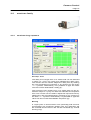
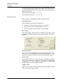
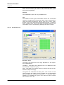
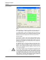
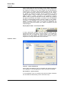
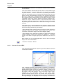
After starting camware, the following main window should be
visible:
1.1
Signs and Symbols
The following signs and symbols are used throughout this
manual:
user's manual pco.camware 12/2004
Camware
Page 7
Disregarding this symbol and the accompanying text warning notices may result in the risk of death.
Disregarding this symbol and the accompanying text warning notices may result in system damage and data loss.
This symbol and the accompanying text point out tips, hints
and other useful information.
•
These Symbols denote
enumerations and listings.
Text which refers to software menus and related information is written in Courier typeface with a fixed width.
1.2
New Features of pco.camera
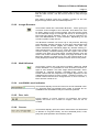
1.2.1
Accept Button
Important changes in the general structure of the relationship
between the camera and the computer for pco.camera have
resulted in the camera, itself, doing more "guess" work,
which had previously been done by the computer.
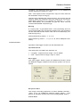
Changes to the camera control sheets must be completed
by pressing the "Accept" button in the lower right corner of
the "Camera Control" window. If the "Accept" button is not
pressed, these changes will be ignored and lost. If the
changes are within the allowed condition limits of the camera, a message is sent to the computer, the button disappears and the green lamp will be highlighted. If an illegal
change was attempted, the camera will not accept the
change and the red lamp will be highlighted.
user's manual pco.camware 12/2004
Camware
Page 8
1.3
Image Data Alignment
1.3.1
MSB (Most Significant Bit) Alignment
With the new pco.camera system, camware was converted
to an MSB image data alignment. This change was in response to customer comments, that only black images could
be seen, when the image files were opened with image processing software. This happened because the 16bit values
were filled with real intensity values for example a maximum
of 4096 counts for a 12bit camera. If a 16bit image was
opened, in most cases the displayed image would be scaled
to the absolute maximum of 65536, of which 4096 is only a
small amount. As a consequence, the displayed image appeared black and seemed to be empty.
For all image data, it doesn't matter which dynamic (10bit,
12bit or 14bit) are MSB or left aligned. This means, that all
corresponding data are shifted or multiplied, and that the
maximum possible value is stored as the maximum 16bit
number (65536). As a result, even 10bit data appears larger,
because a full range pixel value of 1024 for 10bit would be
stored as 65536. Every pixel value has been multiplied by 64
(2 ) to achieve the MSB alignment.
6
If necessary for image processing purposes, the original
10bit values can easily be reconstructed by a simple division
by 64 for each pixel. No image information is lost, distorted
or changed by the MSB alignment.
1.3.2
LSB (Least Significant Bit) Alignment
In earlier versions of camware, image data was stored using
LSB alignment. However, this method had shortcomings and
is no longer used in camware. Using LSB alignment the pixel
values are stored as they are recorded. Since there are no 10
or 12 or 14bit image formats, only 8bit and 16bit, all image
types must be stored as 16bit images.
user's manual pco.camware 12/2004
Camware
Page 9
LSB alignment is also called right aligned. The disadvantage
of some image processing software packages is that they
open images and display them simply minimum-maximum
scaled to the data format instead of the image content.
Therefore, a maximum exposed 10bit image (1024 counts)
will appear totally black when stored as 16bit image data.
The software scales from 0-65536 for display of 0-255 grey
values, resulting in the darkest grey level step of 8192
counts, which is larger than 1024. As a result, no image can
be seen.
To solve this problem, now camware stores images MSB
aligned.
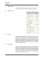
1.4
If no camera is connected
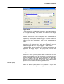
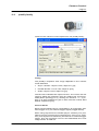
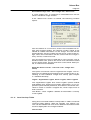
If camware is started with no camera connected to the PC or
with cameras switched off, it starts in demo mode, which
means that all image processing features are available. The
user only has to tell camware which type of images will be
opened. For that purpose, the "Demo Mode Setup" window
opens and asks for the corresponding input.
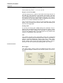
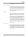
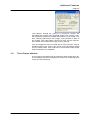
Resolution
The drop down list offers the existing image sensor spatial
resolutions of all PCO camera systems. The user selects the
resolution of the images to be opened. Alternatively, the spatial resolution can be adjusted by activating the text fields
and typing in the values:
X: horizontal resolution
Y: vertical resolution
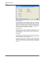
The second drop down list, "12bit", offers the selection of
the dynamic resolution (number of grey values in the image).
Furthermore, if double shutter images have been recorded
and should be opened, the corresponding checkbox should
be checked.
Color
user's manual pco.camware 12/2004
Camware
Page 10
With the radio buttons, the user can specify whether the image type is monochrome or color.
Alignment
These two radio buttons adjust whether MSB aligned ("upper") or LSB aligned ("lower") images have been stored (see
chapter before).
user's manual pco.camware 12/2004
Quick Overview
Page 11
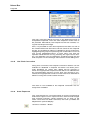
2
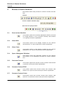
Quick Overview
The toolbar buttons are pictured along with the corresponding chapters, denoted by brackets, for further explanations.
Print (4.1.9)
B/w window (4.4.1) - color window (4.4.2) - histogram (4.4.3)
Camera Control (3) - convert control b/w (4.4.4) - convert
control color (4.4.5)
Auto range peak (5.8) - auto range crop (5.9) - auto balance
color (5.10)
Auto exposure (4.2.6)
Live preview (4.3.1) - acquire picture (4.3.2)
Master gain (5.14)
Pixel value (5.15)
Start record (5.17) - play record (5.18) - stop record (5.19)
Setup recorder (4.3.5)
Replay navigation (5.21)
Recorder browser (4.4.6)
Multi window (4.4.7)
Mathematical functions (4.1.10)
user's manual pco.camware 12/2004
Camera Control
Page 12
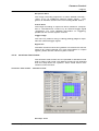
3
Camera Control
The "camera control" window is the main interface for all
camera settings. Here, camera delay and exposure times are
adjusted, vertical and horizontal binning can be selected, the
camera can be set to various trigger modes, a region of interest (ROI) can be selected and information about the camera is displayed.
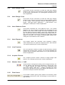
The camera control window can be started by selecting the
proper command in the "Camera"-Menu or by pressing the
following button:
Camware automatically detects the camera type
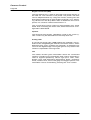
3.1
pco.camera family
This section describes the settings for the pco.camera system. The camera control dialog always adapts to the camera
type connected. For pco.camera the camera control settings
are spread over five property sheets.
The most important change in the use of the camera control
for the pco.camera system is that changes that have been
made within the camera control window must be sent to the
camera to be acknowledged. Therefore, after changes in
each sheet, the visible "accept" button must be pressed.
After that, the changes will be sent to the camera. A green
lamp in the lower right corner of the control window indicates that the changes have been acknowledged and made.
A red lamp signals an error.
If the "accept" button were not pressed, the user would
continue recording with previous or unknown settings. The
camera control dialog does not revert to previously "accepted" settings.
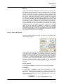
Timing
The "Timing" sheet enables the control of delay and exposure time as well as the "Trigger Mode".
user's manual pco.camware 12/2004
Camera Control
Page 13
Trigger Mode
If "Auto Sequence" is selected, press the "Start Record" button to begin recording. The camera will optimize the image
recording to achieve the best possible frame rate.
Use the "Soft Trigger" if single images need to be recorded
with GUI control. The user must press the "Start Record"
button to enable the recording. Then single images can be
acquired by pressing the "Single Trigger" – button (see 5.13
and 5.17) with the yellow flash, next to the "Start Record"
button.
If "External Exp. Start" is selected, the image acquisition is
triggered by an external signal. It is also possible to force a
software trigger with the "Single Trigger" – flash button.
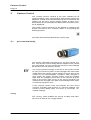
If "External Exp. Ctrl" is selected, an external signal, which is
applied to the trigger input at the pco.power, controls the
start and the duration of the exposure.
Timing
The timing values (exposure and delay times) can be adjusted in various ways. It is possible to click onto the red triangles and move them with the mouse, or to change the values using the edit control. Here, the values can be edited directly, by clicking into the edit control, or by using the
up/down control or the slider on the right. The slider and the
up/down control refer to the blue highlighted unit.
Sensor (Size)
Within the Sensor (Size) sheet it is possible to adjust the
sensor format, the binning and the region of interest (ROI).
user's manual pco.camware 12/2004
Camera Control
Page 14
Binning
Binning combines neighbouring pixels (in either the horizontal or vertical direction) to form super pixels. It increases the
light signal of the remaining pixels and decreases the spatial
resolution of the total image, which is recorded. To a certain
extent, it increases the frame rate.
ROI
The ROI (region of interest) selects only a part of the sensor
to be read out, in order to speed up the frame rate and to
save memory. The ROI can be changed by clicking on the
ROI window while selecting a new rectangle, or by directly
accessing one of the four ROI limiting values. They can be
edited within the edit box, increased or decreased by the
up/down control or by using the slider. Additionally, the ROI
setting can be reset to maximum extent by pressing the "Set
to max" button. Another option allows ROI mouse adjustment, as described in Section 7.2.
Sensor format
Some image sensors have the option to readout a standard
size (effective pixels recommended by the sensor manufacturer) or an extended size, which adds further exposed pixels, which can be helpful for calibration or control purposes.
Sensor (Misc.)
The Sensor (Misc.) sheet offers options to control image
quality and additional camera system parameters.
user's manual pco.camware 12/2004
Camera Control
Page 15
Pixelclock
The Pixelclock sets the clock frequency and therefore the
image sensor readout speed. The lower the pixelclock is set,
the higher the image quality will be. At lower pixelclock settings, it is sufficient to read out at a lower bandwidth, which
results in lower readout noise. The higher the pixelclock is
set, the faster the image sensor is read out by the camera,
achieving higher frame rates.
ADC Converter
Using two analog-to-digital converters (ADC), rather than
one, will decrease the readout time. Using two ADCs will
force the ROI to be symmetrical in the horizontal direction.
With two ADCs, the left half of the image is converted by the
first ADC and the right half of the image is simultaneously
converted by the second ADC. The readout time will be
shortened by half.
Double Image
These radio buttons select the camera's double shutter / exposure function such that the readout time of the first image
can be used to record a second subsequent image. This feature is widely used for particle image velocimetry (piv) measurements.
IR Sensitivity
If available, these buttons use a special image sensor control
method, allowing greater sensitivity in the near infrared spectral range, in most cases, at the expense of decreased antiblooming performance.
Offset Control
To deliver all image evaluation information, it is necessary to
add a certain signal level to the real signal, to enable the
measurement of the total noise floor (if the offset would be
zero, an unknown amount of noise would be cut off, since a
negative light signal is not possible). The stability of this offset is usually guaranteed by a proper temperature control
and a software control, which uses the information of "dark
user's manual pco.camware 12/2004
Camera Control
Page 16
pixel" information from the sensor limits. Further, algorithms
must be applied to match the sensor performance if 2 ADCs
are used for readout. All this can be done automatically (Offset Control - Auto) or can be switched off (Offset Control Off), for total user control. The addition of an offset level is
not influenced by these radio buttons, but rather through
software control.
Conversion Factor
Using the values from the dropdown list, the corresponding
conversion factor can be selected. The conversion factor defines how many charges (electrons), which have been generated by light in the image sensor in each pixel, are necessary
to generate one count (one intensity level) in the digital image. Therefore, the conversion factor describes the gain that
is applied to the signal before it is converted into a digital
value.
Cooling Setpoint
The cooling setpoint (if available) adjusts the temperature
that should be reached by the camera system. The user
should not set the cooling setpoint to the lowest possible
temperature. In case ambient temperature drifts, the controller will not have any overhead available for adjustment. The
window shows the readout temperature of the image sensor
and the adjusted temperature. The adjustment controls
should be used to select an appropriate temperature. The
lower the temperature, the less dark current is accumulated,
which is only important for longer exposure times. If exposure times are in the ms range or shorter, the lower temperature has no major influence. To keep the offset as constant
as possible, moderate cooling is sufficient.
When the "Default" button is pressed, it sets the cooling
temperature back to the default setting.
user's manual pco.camware 12/2004
Camera Control
Page 17
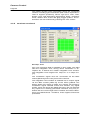
camRAM
The camRAM tab gives control of three available memory
segments of "camRAM", the camera's built in memory.
Although the camera has four memory segments, only three
of them are accessible with camware, because one very
small memory segment is used for the live preview image
handling. Therefore, nearly all camRAM space can be freely
distributed between the three available memory segments.
Activating a camRAM Segment
To activate a camRAM memory segment, use the radio buttons to make a selection. If a subsequent image recording is
started, this segment will be used.
camRAM Settings
The amount of memory for the active memory can be adjusted by using the number boxes, sliders (activated by
pressing the arrow down buttons) or by clicking on one of
the pie limiting lines and moving the mouse while holding the
mouse button down. Neighboring memory segments will be
adapted. The resulting memory sizes (in MB) are displayed in
the status windows.
Recording
The Recording sheet gives memory operation control (recorder mode), an additional external control signal (acquire
mode) and an optional image integrated time stamp for better image sequence management.
user's manual pco.camware 12/2004
Camera Control
Page 18
Recorder Mode
In sequence mode, the camera will stop after the active
memory segment of the camRAM is filled once. The camRAM level indicator (see 5.24) displays the memory segment
fill level. In ring buffer mode, the camera will record continuously into the memory segment. If the end of the segment is
reached, the oldest images are overwritten, achieving a cyclical recording, until recording is stopped.
Acquire Mode
The acquire mode enables or disables recording by an external static signal. If set to external, the camera will only record images if the external signal is valid and therefore enables recording.
Timestamp
A timestamp can be placed into the upper left corner of each
image. This option, which is selected using the radio buttons,
includes: off, binary or binary with text.
In "binary mode", the first 16 pixels of each image will be
filled with the time stamp. In "binary and ASCII" a timestamp
text will be placed into the upper left corner of each image
and, as such, the content of the image will be replaced by
the text.
user's manual pco.camware 12/2004
Camera Control
Page 19
3.2
sensicam family
3.2.1
sensicam long exposure
Del./Exp. Time
The delay time ranges from 0 to 1000s and can be selected
in steps of 1 [ms]. The green bar indicates the delay time.
The mouse can be used to adjust the delay time by shifting
the red arrowhead (up pointing) or by clicking on the green
"+/-" symbols. Alternatively, it is possible to type the value
into the number field beside "Delay [s]".
The exposure time ranges from 0 to 1000s and can be selected in steps of 1 [ms]. The blue bar indicates the exposure
time. The mouse can be used to adjust the exposure time by
shifting the red arrowhead (down pointing) or by clicking on
the blue "+/-" symbols. Alternatively it is possible to type the
value into the number field beside "Exposure [s]".
Binning
A "super pixel" is formed when rows (vertically) and columns
(horizontally) are combined. Please note, the resolution will
be reduced and the frame rate will be increased (by vertical
binning only).
user's manual pco.camware 12/2004
Camera Control
Page 20
Horizontal Binning: factor - 1, 2, 4, 8
Vertical Binning: factor - 1, 2, 4, 8, 16, 32
Region of Interest (ROI)
The ROI selects only a part of the total CCD image sensor to
be read out. The minimum is 32 pixels x 32 pixels. The area
can be adjusted either by using the mouse, clicking into the
ROI field and drawing an appropriate rectangle, or by selecting values from the drop down lists to determine the corner
points. For another method see section 7.2.
The unused lines will be read out approximately four times
faster, thus increasing the frame rate, while decreasing the
amount of image data.
Analog Gain
A normal and a high gain (-6dB) setting are available. This influences the integrated gain and the conversion factor, which
describes how many charges are necessary to generate one
count in the digital image. The higher gain is only useful if the
camera is operated in binning mode
Info
This status window gives information about the connected
camera, including type of sensicam (this code is important in
case of support questions), sensor type (b/w, color, VGA,
SVGA), CCD- and electronics temperature, delay- /exposure
times, readout time, frame rate [fps], trigger options. The information can be reviewed by pressing the "Info" button.
Frame Control
Set Trigger
The "Set Trigger" button opens an additional window, where
the different trigger modes of the camera system can be selected:
user's manual pco.camware 12/2004
Camera Control
Page 21
Sequence Start
The image recording sequence is either started internally "Auto" or by an additional external trigger signal - "Triggered" at the BNC socket of the PCI frame grabber board.
Frame Start
The image recording or exposure will be started in "Sequential" or "Simultaneous" mode or by an external trigger signal
"Triggered". For more detailed information on triggering,
please see the camera system manual.
Trigger Edge
The user may select a rising or falling (trailing) edge to represent the external trigger signal.
Signal Out
The BNC socket at the frame grabber PCI board can also be
used as an output channel. For more information on output
signals, please see the camera system manual.
3.2.2
sensicam fast shutter
The sensicam fast shutter can be operated in standard mode
and in a fast cycle mode. The desired mode can be selected
from the drop down list "Options". Each mode has its own
camera control window.
sensicam fast shutter - standard mode
Del./Exp. Time
user's manual pco.camware 12/2004
Camera Control
Page 22
Delay times range from 0 to 1ms and are selectable in steps
of 100 [ns]. To enter and adjust the values, select the corresponding number field and type in the value.
Exposure times range from 100ns to 1ms and are selectable
in steps of 100 [ns]. To enter and adjust the values, select
the corresponding number field and type in the value.
A maximum of 10 pairs (delay + exposure time) can be defined. If only a single exposure or less than 10 pairs are required, simply set the unused times to 0000.000.
Multiple exposure operation example
Exposure 1: delay 20µs - exposure 5µs
Exposure 2: delay 1ms - exposure 0
Exposure 3: delay 1ms - exposure 1ms
Exposure 4: delay 1µs - exposure 1ms
Exposure 5: delay 0 - exposure 100µs
Hints & Notes
•
For exposure 2, the exposure time has been set to 0. This
results in a delay of 1ms.
•
Exposure 4 has a true duration of 1.1ms, since the delay
of exposure 5 is 0, i.e. exposure 5 follows directly exposure 4. This results in an exposure time larger than 1ms.
Trigger
Here the trigger operation mode can be selected by these
radio buttons. The image recording sequence can either be
started internally - "Auto Sequential", which is only available
in sensicam fast shutter "Standard Mode" or by an additional
external trigger signal - "Ext. falling Edge" (means trailing
edge) or "Ext. rising Edge" at the BNC socket of the PCI
frame grabber board.
Binning
A "super pixel" is generated when rows (vertically) and columns (horizontally) are combined. Please note, the resolution
will be reduced and the frame rate will be increased (by vertical binning only).
user's manual pco.camware 12/2004
Camera Control
Page 23
Horizontal Binning: factor - 1, 2, 4, 8
Vertical Binning: factor - 1, 2, 4, 8, 16, 32
Region of Interest (ROI)
The ROI selects only a part of the total CCD image sensor to
be read out. The minimum is 32 pixels x 32 pixels. The area
can be adjusted either by using the mouse, clicking into the
ROI field and drawing an appropriate rectangle, or by selecting values from the drop down lists to determine the corner
points. For a further method see section 7.2.
The unused lines will be read out approximately four times
faster thus increasing the frame rate, while the amount of image data is decreased.
Options
The sensicam fast shutter "Standard" mode or the "Fast Cycles" mode may be selected from the drop down list.
Analog Gain
A normal and a high gain (-6dB) setting are available. This influences the integrated gain and the conversion factor, which
describes how many charges are necessary to generate one
count in the digital image. The higher gain is only useful if the
camera is operated in binning mode
Info
This status window gives information about the connected
camera, including type of sensicam (this code is important in
case of support questions), sensor type (b/w, color, VGA,
SVGA), CCD and electronics temperature, delay- /exposure
times, readout time, frame rate [fps] and trigger options. The
information can be reviewed by pressing the "Info" button.
user's manual pco.camware 12/2004
Camera Control
Page 24
sensicam fast shutter - fast cycles mode
Del./Exp. Time
Delay times range from 0 to 1ms and are selectable in steps
of 100 [ns]. To enter and adjust the values, select the corresponding number field and type in the value.
Exposure times range from 100ns to 1ms and are selectable
in steps of 100 [ns]. To enter and adjust the values, select
the corresponding number field and type in the value.
Within each cycle block, the corresponding delay + exposure
time pair is repeated according to the cycle number, which
can be typed in, if the corresponding number field is selected. Then the next cycle block begins. The cycles range
from 0 to 1000. If the number of cycles is equal to 0, the
block is ignored and skipped. A single delay + exposure time
pair may not be smaller than 1µs.
user's manual pco.camware 12/2004
Camera Control
Page 25
Exposure 1: delay - 800ns, exposure - 1ms, cycles - 12
Exposure 2: delay - 2µs, exposure - 500µs, cycles - 1
Exposure 3: delay - 400ns, exposure - 60µs, cycles - 3
Exposure 4: delay - 1µs, exposure - 1ms, cycles - 5
Exposure 5: delay - 0, exposure - 0, cycles - 0
Hints & Notes
•
Each cycle must be triggered separately!
•
At exposure 1, there are 12 exposures with an 800ns delay time and a 1ms exposure time for each.
•
Then, there is one exposure with a delay of 2µs and an
exposure time of 500µs.
•
At exposure 3, there are 3 exposures with 400ns delay
and 60µs exposure time.
•
At exposure 4, there are 5 exposures with 1µs delay and
1ms exposure time.
•
Finally, the last block is ignored since the cycle number is
set to 0.
Trigger
The user may select the trigger edge by using the radio buttons. The image recording sequence can be started by an
additional external trigger signal - "Ext. falling Edge" (means
trailing edge) or "Ext. rising Edge" at the BNC socket of the
PCI frame grabber board.
Binning
A "super pixel" is generated when rows (vertically) and columns (horizontally) are combined. Please note, the resolution
will be reduced and the frame rate will be increased (by vertical binning only).
Horizontal Binning: factor - 1, 2, 4, 8
Vertical Binning: factor - 1, 2, 4, 8, 16, 32
user's manual pco.camware 12/2004
Camera Control
Page 26
Region of Interest (ROI)
The ROI selects only a part of the total CCD image sensor to
be read out. The minimum is 32 pixels x 32 pixels. The area
can be adjusted either by using the mouse, clicking into the
ROI field and drawing an appropriate rectangle, or by selecting values from the drop down lists to determine the corner
points. For a further method see section 7.2.
The unused lines will be read out approximately four times
faster thus increasing the frame rate, while the amount of image data is decreased.
Options
The sensicam fast shutter "Standard" mode or the "Fast Cycles" mode may be selected from the drop down list.
Analog Gain
A normal and a high gain (-6dB) setting are available. This influences the integrated gain and the conversion factor, which
describes how many charges are necessary to generate one
count in the digital image. The higher gain is only useful if the
camera is operated in binning mode
Info
This status window gives information about the connected
camera, including type of sensicam (this code is important in
case of support questions), sensor type (b/w, color, VGA,
SVGA), CCD- and electronics temperature, delay- /exposure
times, readout time, frame rate [fps] and trigger options. The
information can be reviewed by pressing the "Info" button.
user's manual pco.camware 12/2004
Camera Control
Page 27
3.2.3
sensicam double shutter
Del./Exp. Time
With the sensicam double shutter, the delay and exposure
time settings are not accessible in the camera control window, so the corresponding input fields appear in gray color.
The exposure time can only be controlled via external input
signal, which must be supplied at the BNC socket [TRIG IN]
at the frame grabber PCI board.
For more detailed information on the [TRIG IN] input, please
see the sensicam double shutter / sensicam qe double shutter manual.
Trigger
The user may select the trigger edge by using the radio buttons. The image recording sequence can be started by an
additional external trigger signal - "Ext. falling Edge" (means
trailing edge) or "Ext. rising Edge" at the BNC socket of the
PCI frame grabber board.
Binning
A "super pixel" is generated when rows (vertically) and columns (horizontally) are combined. Please note, the resolution
will be reduced and the frame rate will be increased (by vertical binning only).
Horizontal Binning: factor - 1, 2, 4, 8
Vertical Binning: factor - 1, 2, 4, 8, 16, 32
Region of Interest (ROI)
user's manual pco.camware 12/2004
Camera Control
Page 28
The ROI selects only a part of the total CCD image sensor to
be read out. The minimum is 32 pixels x 32 pixels. The area
can be adjusted either by using the mouse, clicking into the
ROI field and drawing an appropriate rectangle, or by selecting values from the drop down lists to determine the corner
points. For a further method see section 7.2.
The unused lines will be read out approximately four times
faster thus increasing the frame rate, while decreasing the
amount of image data.
Options
This drop down list offers two double shutter operation
modes:
•
Double Short - dead time 200ns
•
Double Long - dead time 1µs
and two fast shutter operations modes:
•
Standard
•
Fast Cycles
Analog Gain
A normal and a high gain (-6dB) setting are available. This influences the integrated gain and the conversion factor, which
describes how many charges are necessary to generate one
count in the digital image. The higher gain is only useful if the
camera is operated in binning mode
Info
This status window gives information about the connected
camera, including type of sensicam (this code is important in
case of support questions), sensor type (b/w, color, VGA,
SVGA), CCD- and electronics temperature, delay- /exposure
times, readout time, frame rate [fps] and trigger options. The
information can be reviewed by pressing the "Info" button.
user's manual pco.camware 12/2004
Camera Control
Page 29
3.2.4
sensicam qe
Del./Exp. Time
The delay and exposure time range depends on the operation mode setting:
LongExp - The delay time ranges from 0 to 1000s and can
be selected in steps of 1 [ms].
Fast - The delay time ranges from 0 to 10ms and can be selected in steps of 100 [ns].
The green bar indicates the delay time. The mouse can be
used to adjust the delay time by shifting the red arrowhead
(up pointing) or by clicking on the green "+/-" symbols. Alternatively it is possible to type the value into the number field
beside "Delay [s]".
LongExp - The exposure time ranges from 1ms to 1000s and
can be selected in steps of 1 [ms].
Fast - The exposure time ranges from 500ns to 10ms and
can be selected in steps of 100 [ns].
Double - The exposure of two separate full frame images. It
is controlled via the external trigger input signal at the frame
grabber PCI board.
The blue bar indicates the exposure time. The mouse can be
used to adjust the exposure time by shifting the red arrowhead (down pointing) or by clicking on the blue "+/-" symbols. Alternatively it is possible to type in the value into the
number field beside "Exposure [s]".
The selection of the exposure time is internally generated in
steps of 156.25ns. Therefore, the real value for short exposure times represents only an approximation of the selected
exposure time value.
Binning
user's manual pco.camware 12/2004
Camera Control
Page 30
A "super pixel" is generated when rows (vertically) and columns (horizontally) are combined. Please note, the resolution
will be reduced and the frame rate will be increased (by vertical binning only).
Horizontal Binning: factor - 1, 2, 4, 8
Vertical Binning: factor - 1, 2, 4, 8, 16
Frame Control
Here operation and trigger modes can be selected.
Operation Mode
The dropdown list offers the selection of:
•
LongExp - exposure time range: 1ms to 1000s
•
Fast - exposure time range: 500ns to 10ms
•
Double - double shutter exposure of 2 images
Set Trigger
The "Set Trigger" button opens an additional window, where
the different trigger modes of the camera system can be selected:
Sequence Start
The image recording sequence is either started internally "Auto" or by an additional external trigger signal - "Triggered" at the BNC socket of the PCI frame grabber board.
Frame Start
The image recording or exposure will be started in "Sequential" or "Simultaneous" mode or by an external trigger signal
"Triggered". For more detailed information on triggering,
please see the camera system manual.
Trigger Edge
The user may select a rising or falling (trailing) edge to represent the external trigger signal.
user's manual pco.camware 12/2004
Camera Control
Page 31
Signal Out
The BNC socket at the frame grabber PCI board can also be
used as an output channel. For more information on output
signals, please see the camera system manual.
Region of Interest (ROI)
The ROI selects only a part of the total CCD image sensor to
be read out. The minimum is 32 pixels x 32 pixels. The area
can be adjusted either by using the mouse, clicking into the
ROI field and drawing an appropriate rectangle, or by selecting values from the drop down lists to determine the corner
points. For a further method see section 7.2.
The unused lines will be read out approximately four times
faster, increasing the frame rate, while decreasing the
amount of image data.
Analog Gain
A normal and a high gain (-6dB) setting are available. This influences the integrated gain and the conversion factor, which
describes how many charges are necessary to generate one
count in the digital image. The higher gain is only useful if the
camera is operated in binning mode
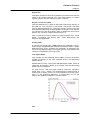
Low Light Mode
Two modes can be selected, which differ in terms of camera
system sensitivity in the near infrared and in anti-blooming
performance.
Default (blue curve) - this is the standard light mode, which is
useful for all exposure times up to 1000s. The anti-blooming
performance is optimal.
On (red curve) - this low light mode is useful for exposure
times from 1ms - 1000s. The anti-blooming performance is
reduced to a factor of four for over-exposure, but the sensitivity i.e. the quantum efficiency is maximized, as can be
seen in the quantum efficiency curves below.
Info
user's manual pco.camware 12/2004
Camera Control
Page 32
This status window gives information about the connected
camera, including type of sensicam (this code is important in
case of support questions), sensor type (b/w, color, VGA,
SVGA), CCD- and electronics temperature, delay- /exposure
times, readout time, frame rate [fps], trigger options. The information can be reviewed by pressing the "Info" button.
3.2.5
sensicam sensimod
Del./Exp. Time
Only one exposure field is available in this mode. This field
sets the integration time, during which modulation is accepted. So, it defines the master integration time window.
The integration time ranges from 100µs to 1s in steps of 1
[µs].
The modulation signal must be connected via the BNC
socket [MOD IN] at the rear panel of the camera.
The integration time window is available as an output signal
via the BNC socket [TRIG IN] at the frame grabber PCI
board. While this signal is HIGH, the camera will accept a
modulation signal. Outside of this time window, any signal
pulses, which are fed to the [MOD IN] input, will not generate
any exposure or clearing processes. However, they may interfere with the CCD image sensor readout and cause distortions and disturbances. Therefore, these signals should be
prevented.
user's manual pco.camware 12/2004
Camera Control
Page 33
The BNC socket [TRIG IN] at the frame grabber PCI board
only has output functionality for this camera system, and no
input functionality.
[MOD IN]
The BNC socket [MOD IN] at the rear panel of the camera
represents the input for external modulation signals, based
on TTL level. Therefore:
•
0V => exposure
•
5V => clear
The input itself is internally secured with a 1kΩ pull-down resistor, i.e. an exposure is made while no external signal is
applied. The characteristic time conditions are:
•
time off ≥ 500ns
•
time on ≥ 500ns
•
maximum frequency 1MHz
There is an intrinsic delay of approximately 30ns between the
trigger signal at the [MOD IN] input and the optical reaction.
Trigger
Auto Sequential operation mode is only available for this
camera model. It is directly triggered by the modulation input
signal.
Binning
A "super pixel" is generated when rows (vertically) and columns (horizontally) are combined. Please note, the resolution
will be reduced and the frame rate will be increased (by vertical binning only).
Horizontal Binning: factor - 1, 2, 4, 8
Vertical Binning: factor - 1, 2, 4, 8, 16
Region of Interest (ROI)
The ROI selects only a part of the total CCD image sensor to
be read out. The minimum is 32 pixels x 32 pixels. The area
can be adjusted either by using the mouse, clicking into the
ROI field and drawing an appropriate rectangle, or by selecting values from the drop down lists to determine the corner
points. For a further method see section 7.2.
user's manual pco.camware 12/2004
Camera Control
Page 34
The unused lines will be read out approximately four times
faster thus increasing the frame rate, while decreasing the
amount of image data.
Options
The "Modulate" option is only available here.
Info
This status window gives information about the connected
camera, including type of sensicam (this code is important in
case of support questions), sensor type (b/w, color, VGA,
SVGA), CCD- and electronics temperature, delay- /exposure
times, readout time, frame rate [fps] and trigger options. The
information can be reviewed by pressing the "Info" button.
3.2.6
sensicam em
Del./Exp. Time
The delay and exposure time range depends on the operation mode setting:
LongExp - The delay time ranges from 0 to 3600s and can
be selected in steps of 1 [ms].
Fast - The delay time ranges from 0 to 75ms and can be selected in steps of 75 [µs].
The green bar indicates the delay time. The mouse can be
used to adjust the delay time by shifting the red arrowhead
(up pointing) or by clicking on the green "+/-" symbols. Alternatively it is possible to type in the value into the number
field beside "Delay [s]".
user's manual pco.camware 12/2004
Camera Control
Page 35
LongExp - The exposure time ranges from 1ms to 3600s and
can be selected in steps of 1 [ms].
Fast - The exposure time ranges from 75µs to 15ms and can
be selected in steps of 75 [µs].
The blue bar indicates the exposure time. The mouse can be
used to adjust the exposure time by shifting the red arrowhead (down pointing) or by clicking on the blue "+/-" symbols. Alternatively it is possible to type the value into the
number field beside "Exposure [s]".
Binning
A "super pixel" is generated when rows (vertically) and columns (horizontally) are combined. Please note, the resolution
will be reduced and the frame rate will be increased (by vertical binning only).
Horizontal Binning: factor - 1, 2, 4, 8
Vertical Binning: factor - 1, 2, (4, 8, 16, 32 for 992pixel resolution)
Frame Control
Operation and trigger modes can be selected here.
Operation Mode
The drop down list offers the selection of:
•
LongExp - exposure time range: 1ms to 3600s
•
Fast - exposure time range: 75µs to 15ms
Set Trigger
The "Set Trigger" button opens an additional window, where
the different trigger modes of the camera system can be selected:
Sequence Start
The image recording sequence is either started internally "Auto" or by an additional external trigger signal - "Triggered" at the BNC socket of the PCI frame grabber board.
Frame Start
user's manual pco.camware 12/2004
Camera Control
Page 36
The image recording or exposure will be started in "Sequential" or "Simultaneous" mode or by an external trigger signal
"Triggered". For more detailed information on triggering,
please see the camera system manual.
Trigger Edge
The user may select a rising or falling (trailing) edge to represent the external trigger signal.
Signal Out
The BNC socket at the frame grabber PCI board can also be
used as an output channel. For more information on output
signals, please see the camera system manual.
Region of Interest (ROI)
The ROI selects only a part of the total CCD image sensor to
be read out. The minimum is 32 pixels x 32 pixels. The area
can be adjusted either by using the mouse, clicking into the
ROI field and drawing an appropriate rectangle, or by selecting values from the drop down lists to determine the corner
points. For a further method see section 7.2.
The unused lines will be read out approximately four times
faster thus increasing the frame rate, while decreasing the
amount of image data.
Electron Multiplying Gain
The drop down list allows the user to set the electron multiplying gain of the emCCD image sensor. The following "Gain
Values" can be selected:
x2, x5, x10, x20, x50, x100, x200, x500, x1000
It should be kept in mind, that with increasing gain, the existing photon noise in low-level signals is also amplified, while
the readout noise stays constant.
Info
This status window gives information about the connected
camera, including type of sensicam (this code is important in
case of support questions), sensor type (b/w, color, VGA,
SVGA), CCD- and electronics temperature, delay- /exposure
times, readout time, frame rate [fps] and trigger options. The
information can be reviewed by pressing the "Info" button.
user's manual pco.camware 12/2004
Camera Control
Page 37
3.3
pixelfly family
These are the camera control options for the pixelfly family.
Timing
The pixelfly's exposure time range depends on the camera
mode selected:
•
Async. Shutter: 10µs to 10ms, steps of 1 [µs]
•
Double Shutter: 1ms to 10s, steps of 1[ms]
•
Video: 10µs to 10ms, steps of 1[µs]
The blue bar indicates the exposure time. The mouse can be
used to adjust the exposure time by shifting the red arrowhead (down pointing) or by clicking on the blue "+/-" symbols. It is also possible to type in value into the number field
beside "Exposure [ms]".
Camera Mode
Each Camera Mode can be controlled by an automatic software trigger or by an external trigger signal (Trigger Mode).
When using asynchronous shutter (Async. Shutter), it is possible to set an exposure time ranging from 10us up to 10ms.
Only one exposure is started by an internal or external trigger
signal. First the exposure occurs and afterwards the CCD
image sensor is read out.
user's manual pco.camware 12/2004
Camera Control
Page 38
In doubleshutter mode (Double Shutter), two exposures will
be released by a trigger signal. First, the exposure of the first
image occurs, then, the first image will be read out. During
the read out time of the first image, the second exposure is
done. Then, the second image will be read out. The possible
exposure times for the first double image range from 10µs up
to 10ms.
In video mode, it is possible to adjust the exposure times
from 1ms up to 10s. A sequence is started by the first trigger
signal. No additional trigger signal is required. The exposure
and the readout of the CCD will be done simultaneously.
In auto exposure mode, an exposure level must be set. This
exposure level can range from to 0% up to 255% (100%
means full range - 4095). The exposure time is controlled
automatically. Only one exposure will be released by a trigger signal.
Binning
A "super pixel" is generated when rows (vertically) and columns (horizontally) are combined. Please note, the resolution
will be reduced and the frame rate will be increased (by vertical binning only).
Horizontal Binning: factor - 1, 2
Vertical Binning: factor - 1, 2 (VGA CCD image sensors 1, 2,
4)
Analog Mode
In analog mode, a normal and a high gain (+6dB) setting are
available. This influences the integrated gain and the conversion factor, which describes how many charges are necessary to generate one count in the digital image.
Info
This status window gives information about the connected
camera, including type of pixelfly (this code is important in
case of support questions), sensor type (b/w, color, VGA,
SVGA), CCD- and electronics temperature, delay- /exposure
times, readout time, frame rate [fps] and trigger options. The
information can be reviewed by pressing the "Info" button.
user's manual pco.camware 12/2004
Camera Control
Page 39
3.4
dicam pro
Single Trigger Mode
Mode
Three operation modes are available on the drop down list:
"Single Trigger", "Multi Trigger" and "Double Shutter".
In Single Trigger Mode, one delay and exposure time pair
can be set, which is released with a single trigger. This can
be repeated from 1 to 256 times, as chosen in the "Loops"
field. After completing all the loops, one image is read out
from the CCD image sensor. The minimum and maximum
delay values and exposure times depend on the high voltage
pulse unit, which is used in the camera. There are a variety of
options available.
The trigger mode can be selected either for software trigger "Auto" or external hardware trigger - "Extern". For detailed
trigger information, please see the separate camera system
manual.
user's manual pco.camware 12/2004
Camera Control
Page 40
Phosphor/MCP
The phosphor "Decay" time of the image intensifiers phosphor screen is given in [ms]. Each phosphor has a specific
decay time, depending on the applied dye material. This setting does not change the specific decay time of the integrated image intensifier, but it extends the integration time of
the CCD image sensor.
Select the "Gain" by entering the "Gain [%]" field and typing
in the value. The accepted values range from 0.0 to 100.0%.
For optimal operation, the gain should be set at 80% to
100%. Using an intensifier gain of less than 50% is similar to
the sensitivity already available in state of the art CCD camera systems.
The image intensifier is the most delicate and sensitive part
of the entire camera system. Its lifetime is decisively influenced by the photocathode current (photo effect). The best
way to preserve the photocathode is by setting a high Gain
(in Phosphor/MCP Gain), as a small amount of input light
generates a low photocathode current, but produces a high
light output to achieve a high dynamic image on the CCD
image sensor. The lifetime also depends on the number of
exposures and the image intensifier's repetition rate.
If the image is overexposed, do not lower the image intensifier gain. Instead attenuate the light impinging on the photocathode by, e.g. closing the aperture or adding a neutral
gray filter to the optical input.
Del./Exp. Time
The delay and exposure time pairs can be adjusted by entering the appropriate values into the corresponding number
fields.
•
delay time range: 0 to 1000s
•
exposure time range: 3ns to 1000s (the shortest exposure
time depends on the camera system specifications)
•
loop: 1 to256
The delay and exposure time value are a combination of the
values in the [ms] and the [ns] field.
Binning
A "super pixel" is generated when rows (vertically) and columns (horizontally) are combined. Please note, the resolution
will be reduced and the frame rate will be increased (by vertical binning only).
Horizontal Binning: factor - 1, 2, 4, 8
Vertical Binning: factor - 1, 2, 4, 8, 16, 32
Region of Interest (ROI)
The ROI selects only a part of the total CCD image sensor to
be read out. The minimum is 32 pixels x 32 pixels. The area
can be adjusted either by using the mouse, clicking into the
ROI field and drawing an appropriate rectangle, or by select-
user's manual pco.camware 12/2004
Camera Control
Page 41
ing values from the drop down lists to determine the corner
points. For a further method see section 7.2.
The unused lines will be read out approximately four times
faster thus increasing the frame rate, while decreasing the
amount of image data.
Analog Gain
A normal - "Gain normal" and a high gain "Gain +6dB" setting is available. This influences the integrated gain and
therefore the conversion factor, which describes how many
charges are necessary to generate one count in the digital
image. The higher gain is only useful if the camera is operated in binning mode.
Info
This status window provides information about the connected camera, including type of dicam pro (this code is important in case of support questions), sensor type (b/w, VGA,
SVGA), CCD- and electronics temperature, delay- /exposure
times, readout time, frame rate [fps] and trigger options. The
information can be reviewed by pressing the "Info" button.
Multi Trigger
user's manual pco.camware 12/2004
Camera Control
Page 42
Mode
The drop down list offers three operations modes: "Single
Trigger", "Multi Trigger" and "Double Shutter".
In Multi Trigger Mode, it is possible to take multi exposures,
each started with one trigger. This can be repeated from one
to 256 times as chosen in the "Loops" field. After completing
all the loops, one image is read out from the CCD. The minimum and maximum values of delay and exposure times depend on the high voltage pulse unit used in the camera system. There are a variety of options available.
The trigger mode can be selected either for software trigger "Auto" or external hardware trigger - "Extern". For detailed
trigger information, please see the separate camera system
manual.
Phosphor/MCP
The phosphor "Decay" time of the image intensifiers phosphor screen is given in [ms]. Each phosphor has a specific
decay time, depending on the applied dye material. This setting does not change the specific decay time of the integrated image intensifier, but it extends the integrations time
of the CCD image sensor.
To select the "Gain", enter the "Gain [%]" field and type in
the desired value. The accepted values range from 0.0 to
100.0%. For optimal operation, the gain should be set at
80% to 100%. Using an intensifier gain of less than 50% is
similar to the sensitivity already available in state of the art
CCD camera systems.
The image intensifier is the most delicate and sensitive part
of the whole camera system. Its lifetime is decisively influenced by the photocathode current (photo effect). The best
way to preserve the photocathode is by setting a high Gain
(in Phosphor/MCP Gain), as a small amount of input light
generates a low photocathode current, but produces a high
light output to achieve a high dynamic image on the CCD
image sensor. The lifetime also depends on the number of
exposures and the intensifier's repetition rate.
If the image is overexposed, do not lower the image intensifier gain. Instead, attenuate the light incident on the photocathode by, e.g. closing the aperture or adding a neutral
gray filter to the optical input.
Del./Exp. Time
The delay and exposure time pairs can be adjusted by entering the appropriate values into the corresponding number
fields.
•
delay time range: 0 to 1000s
•
exposure time range: 3ns to 1000s (the shortest exposure
time depends on the camera system specifications)
•
loop: 1 to 256
The delay and exposure time value are a combination of the
values in the [ms] and the [ns] field.
user's manual pco.camware 12/2004
Camera Control
Page 43
Binning
A "super pixel" is generated when rows (vertically) and columns (horizontally) are combined. Please note, the resolution
will be reduced and the frame rate will be increased (by vertical binning only).
Horizontal Binning: factor - 1, 2, 4, 8
Vertical Binning: factor - 1, 2, 4, 8, 16, 32
Region of Interest (ROI)
The ROI selects only a part of the total CCD image sensor to
be read out. The minimum is 32 pixels x 32 pixels. The area
can be adjusted either by using the mouse, clicking into the
ROI field and drawing an appropriate rectangle, or by selecting values from the drop down lists to determine the corner
points. For a further method see section 7.2.
The unused lines will be read out approximately four times
faster thus increasing the frame rate, while decreasing the
amount of image data.
Analog Gain
A normal - "Gain normal" and a high gain "Gain +6dB" setting is available. This influences the integrated gain and
therefore the conversion factor, which describes how many
charges are necessary to generate one count in the digital
image. The higher gain is only useful if the camera is operated in binning mode.
Info
This status window provides information about the connected camera, including type of dicam pro (this code is important in case of support questions), sensor type (b/w, VGA,
SVGA), CCD- and electronics temperature, delay- /exposure
times, readout time, frame rate [fps] and trigger options. The
information can be reviewed by pressing the "Info" button.
user's manual pco.camware 12/2004
Camera Control
Page 44
Double Shutter
Mode
Three operations modes are available with the drop down
list: "Single Trigger", "Multi Trigger" and "Double Shutter".
In "Double Shutter" mode, one trigger starts the exposure of
two images (first image to A and second image to B). The
minimum and maximum values of delay and exposure times
depend on the high voltage pulse unit used in the camera.
Phosphor/MCP
The phosphor "Decay" time of the image intensifier's phosphor screen is given in [ms]. Each phosphor has a specific
decay time, depending on the applied dye material. This setting does not change the specific decay time of the integrated image intensifier, but it extends the CCD image sensor integration time.
To select the "Gain", enter the "Gain [%]" field and type in
the desired value. The accepted values range from 0.0 to
100.0%. For optimal operation, the gain should be set at
80% to 100%. Using an intensifier gain of less than 50% is
similar to the sensitivity already available in state of the art
CCD camera systems.
The image intensifier is the most delicate and sensitive part
of the entire camera system. Its lifetime is decisively influenced by the photocathode current (photo effect). The best
way to preserve the photocathode is by setting a high Gain
(in Phosphor/MCP Gain), as a small amount of input light
generates a low photocathode current, but produces a high
light output to achieve a high dynamic image on the CCD
image sensor. The lifetime also depends on the number of
exposures and the intensifier's repetition rate.
user's manual pco.camware 12/2004
Camera Control
Page 45
If the image is overexposed, do not lower the image intensifier gain. Instead attenuate the light impinging on the photocathode by, e.g. closing the aperture or adding a neutral
gray filter to the optical input.
Del./Exp. Time
The delay and exposure time pairs can be adjusted by entering the appropriate values into the corresponding number
fields.
•
delay time range: 0 to 1000s
•
exposure time range: 3ns to 1000s (the shortest exposure
time depends on the specifications of the camera system)
The delay and exposure time value are a combination of the
values in the [ms] and the [ns] field.
Region of Interest (ROI)
The ROI selects only a part of the total CCD image sensor to
be read out. The minimum is 32 pixels x 32 pixels. The area
can be adjusted either by using the mouse, clicking into the
ROI field and drawing an appropriate rectangle, or by selecting values from the drop down lists to determine the corner
points. For a further method see section 7.2.
The unused lines will be read out approximately four times
faster thus increasing the frame rate, while decreasing the
amount of image data.
Analog Gain
A normal - "Gain normal" and a high gain "Gain +6dB" setting is available. This influences the integrated gain and the
conversion factor, which describes how many charges are
necessary to generate one count in the digital image. The
higher gain is only useful if the camera is operated in binning
mode.
Info
This status window provides information about the connected camera, including type of dicam pro (this code is important in case of support questions), sensor type (b/w, VGA,
SVGA), CCD- and electronics temperature, delay- /exposure
times, readout time, frame rate [fps] and trigger options. The
information can be reviewed by pressing the "Info" button.
user's manual pco.camware 12/2004
Menu Bar
Page 46
4
Menu Bar
In this chapter, the functionality and commands of the different menus in the main menu bar are explained in detail.
4.1
Menu - File
4.1.1
Open
This command should be used to import an image into the
currently active image window. Only files with the extension
and format of "*.b16" and "*.tif" can be imported (b16 - PCO
proprietary binary image format, tif - TIFF image format). If
the recorder is enabled, each imported image will be transferred to the buffer shown in the picture number. The image
itself will be fitted to the current image size. If the recorder is
disabled, the current image sizes will be set to the parameters of the imported image.
4.1.2
Open Set
The "Open Set" command should be used to import a set of
images. The corresponding windows will be opened automatically. A comment window will also be opened, showing
the camera settings with a comment. This command opens
the "Open file" dialog box. Only files with the extension
"*.set" can be imported. The filename of the images is generated by using the following convention: set name plus a
number and the extension "*.b16".
user's manual pco.camware 12/2004
Menu Bar
Page 47
In "recorder mode", the "Open Set" command is automatically disabled.
4.1.3
Open Recorder
This command is used to import a sequence of images. If
more than one camera is connected and an image window is
currently open, the sequence will be loaded to the window
that has received the input focus (the active window). If no
image window is open, the images will be loaded to camera
1.
This command opens the "Open file" dialog box. Only files
with the extension and the format of "*.b16" and "*.tif"
(TIFF16) can be imported.
4.1.4
Save
The "Save" command should be used to save or export the
image, which is displayed in the active window. The command opens the "Save file" dialog box. The image file can
only be saved in "*.b16", "*.fts", "*.tif", "*.bmp" or ASCII format.
Note: be aware of the different storage abilities of the formats, for example "*.bmp" - the bitmap format only allows
for 8bit values to be stored and therefore the image content
of a 12 or 14bit image is reduced, if stored as bitmap.
If more than one camera is connected, it is possible to save
all current images by selecting "Export all images" in the
"Save file" dialog box. With this feature it is possible to save
one image of each active camera within one process step (it
is not necessary to repeat the save process for each camera).
The "Save" command will not be available, if there is no image window open.
4.1.5
Save Set
The "Save Set" command should be used to save or export
the image, which is displayed in the currently active window.
The command opens the "Save file" dialog box. The image
file can only be saved in "*.b16" format. The naming convention is: image file name = set name plus a number and the
"*.b16" extension. After the "Save file" dialog, the user will be
prompted to type in a comment (experimental conditions or
the like) if desired.
user's manual pco.camware 12/2004
Menu Bar
Page 48
This comment is added to the information text file, which includes the actual camera settings. Later, if the set is opened
again for processing purposes or the like, a text window is
displayed which shows all the mentioned information including the comment.
If the recorder has been previously enabled, the "Save Set"
command is not available. The "Save Set" command will not
be available, if there is no image window open.
4.1.6
Save Recorder
The "Save Recorder" command should be used to save or
export image records. If more than one camera is connected
and an image window is currently open, the record of the active window will be saved. The command opens the "Save
file" dialog box. If another image format than "*.b16" or "*.tif"
(16bit) is chosen, image content will be lost, and it will be impossible to reload the images.
The "Save Recorder" command will not be available, if there
is no image window open.
4.1.7
Print Setup
The "Print Setup" command opens the Windows "Print
Setup" dialog box for adjustments and settings of the connected printer(s).
4.1.8
Print Preview
The "Print Preview" command opens a "Print Preview" window.
4.1.9
Print...
The "Print" command should be used to begin printing the
currently displayed image or comment display (if activated).
When there are no image windows open and no comment
windows open, the printout will not be started. The command opens the Windows "Print" dialog box, where options
such as number of copies, destination printer and other options can be selected. The printout will be formatted as
specified by the "Print Setup" (see section 4.1.7).
user's manual pco.camware 12/2004
Menu Bar
Page 49
Shortcut: Toolbar - Button
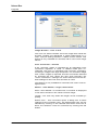
4.1.10 Options
This command opens the "Options" dialog, allowing special
settings.
Options - File settings
TIFF Bit Alignment - Align to MSB
The alignment of the pixel values can be selected here. If the
item is checked off, each pixel value is, for example, shifted
from bit 12 - 1 to bit16 - 5. This removes the "dark image effect" inside other image processing and displaying applications. Check the item, if the camware-generated tiff-files
should be used by other applications.
Users should note that the alignment is a binary shift operation and is not performing a scaling operation!
ASCII file separator
The drop down list allows the user to select the appropriate
separator for the image storage in ASCII format.
Options - View Settings
user's manual pco.camware 12/2004
Menu Bar
Page 50
Image Browser - color or b/w
The user can select whether all of the image tiles inside the
browser window are displayed in either black/white or in
color. The b/w setting results in a faster screen refresh. This
feature is only available for cameras with a color CCD image
sensor.
Color Conversion - Smooth
If the "Smooth" option is checked off, an alternative color
conversion algorithm is used. In default mode (box unchecked), the color is calculated with minimum averaging,
resulting in images with high sharpness. If a smoother image
with "softer" edges is required, this item should be selected
by checking the box. When the user exits camware, the
"Color Conversion" settings are saved and become the default settings for the next time camware is used.
This feature is only available for cameras with color CCD image sensors.
Marker - View Marker, Length, Select Color
When "View Marker" is checked off, a crosshair is displayed
in the active window in the center of each image.
Length - The user may select the length of the crosshair [in
pixels].
Select color - This command opens a dialog box to allow
changes to the crosshair color. The appropriate color can be
selected by clicking on the desired color field. Once this is
done, the selection must be confirmed by clicking the OK
button.
user's manual pco.camware 12/2004
Menu Bar
Page 51
Min/Max - Automatic
This option activates an automatic Min/Max scaling of the
displayed images during record and replay.
This feature should be disabled if there are problems with the
camware response when the automatic scaling is enabled
(due to operating system capacity problems).
DoubleShutter - Paint both images
If checked, this option enables the update of both double
shutter/exposure images during record and replay. The
checkbox should be disabled if camware is not responding
to user interactions in this mode.
Options - Toolbar
Toolbar - Main, Cursor Display, Math. Functions, Recorder
If "Main" is checked, the main toolbar is visible and accessible in camware.
If "Cursor Display" is checked, the cursor readout window is
displayed and updated. This cursor window shows the position and intensity value of the cursor at the particular point in
the image.
If "Math. Functions" is checked, the mathematics tool window will be displayed.
With the "Math. Functions" feature, it is possible to continuously calculate and display the difference between a referuser's manual pco.camware 12/2004
Menu Bar
Page 52
ence image and the actual image. If the "Math. Functions"
feature is activated, every new image will be subtracted from
the reference image or vice versa. Math can be activated by
pressing the "R" button (last acquired image will be copied
to the reference buffer and taken as reference) or the "FlashR" button (a reference image will be acquired). To avoid
negative values, which would not be visible, it is possible to
add an offset. If "Math. Functions" are enabled, a toolbar
button with a green checkmark will be visible. By pressing
the green checkmark the "Math. Functions" can be disabled,
but the corresponding toolbar remains visible. If the "Math.
Functions" are disabled, but they had previously been enabled, a toolbar button with a red cross is displayed. By
pressing the red cross button, the "Math. Functions" can be
enabled again.
Replay Speed Bar - Show Speed Bar
A reply speed bar feature may be selected, which is displayed just below the replay control buttons. The speed bar
allows the user to adjust the replay speed, from very slow
(turtle) to very fast (rabbit). The faster replay speed is useful if
large sets of image data need to be scanned.
Options - Misc
Infotext - Show At Startup
If the "Show At Startup" box is checked, the startup information dialog box will be displayed, when camware is started.
Scroll Mode - Synchronous
If "Scroll Mode" box is checked, all opened image windows
are scrolled simultaneously and in the same way.
user's manual pco.camware 12/2004
Menu Bar
Page 53
Embedded Image Info - View Image Info, Select Info
If "View Image Info" is checked an embedded text will be
shown inside the image window.
If the "Select Info" button is clicked, the following window
opens:
Use this feature if a comment, and/or the time/date the image was acquired and/or the camera number needs to be
stored as visible information on the image. The text will be
placed directly into the image and will cover a part of the image. Since the information will be saved with the image in
every format, it cannot be lost.
Only the large font can be used with a color camera. This is
because each color pixel is the result of a calculation based
on four base pixels. As the small font covers fewer base pixels, it would not be readable.
Multi Win Picture Order - Camera order, Image time
stamp
This option should be used to organise the images. The images can be displayed according to the camera order or according to the individual image time stamp (See chapter
4.1.30 Multi Window).
Logfile - Application Logfile, Driver Logfile, Clear Logfiles
The "Application Logfile" and "Driver Logfile" options enable
and disable error logging and system information. If you experience performance problems, this feature should be activated in order to create a support file, which helps PCO to
find a solution.
The Button "Clear Logfiles" deletes all information currently
in the logfiles.
4.1.11
Load Lookup Table
Using this command loads a lookup table. It offers a Pseudo
Look-Up-Table feature. With the Pseudo LUT feature any
LUT can be loaded with one of four different formats and the
result is displayed in the image windows.
The formats
user's manual pco.camware 12/2004
Menu Bar
Page 54
1. File extension "*.LT1": a file with 768 binary values consisting of 256 x rgb rgb rgb rgb ... (r=red, g=green,
b=blue).
2. File extension "*.LT2": a file with 3x 256 binary values
consisting of 256 x red followed by 256 x green followed
by 256 x blue values.
3. File extension "*.LT3": a file with 768 ASCII values consisting of 256 x rgb rgb rgb rgb ... (r=red, g=green,
b=blue).
4. File extension "*.LT4": a file with 3x 256 ASCII values
consisting of 256 x red followed by 256 x green followed
by 256 x blue.
Either the enclosed predefined LUTs or self-defined LUTs
can be used for pseudo coloring.
4.1.12 Direct Record To File
This command should be used to record images directly
onto the computer's hard disk. The command opens the
"Save file" dialog box. The user must set the number of images to be stored to the disk. If the camera captures images
faster than the computer can write to the disk, images will be
lost. Image display does not interfere with the record process. For current computers, an approximate rate of 4-5
frames per second (fps) is typical.
4.1.13 Record with "Flowfile"
This command should be used to load a flow file. A flow file
contains lines with a delay and an exposure time. Each line
corresponds to one image to be acquired. If the flow file has
15 delay and exposure times then 15 images will be acquired. Before the image is snapped, the corresponding time
values will be sent to the camera. This affects the possible
image frame rate, as additional time is required for setting
the values between two images. Please see the sample flow
files in the application directory (e.g. flow.txt).
4.1.14 Exit
Selecting the "Exit" command exits the program and closes
all camera dialog windows. The PCI-interface-card (if present) and the camera will be reset. Window positions, settings and sizes are stored in the Windows registry and will be
loaded again the next time camware is started.
user's manual pco.camware 12/2004
Menu Bar
Page 55
4.2
Menu - Camera
4.2.1
Camera Control
This command should be used to open the "Camera Control" window (See chapter 2).
Shortcut: Toolbar - Button
4.2.2
Load Camera Settings
With this command, previously saved camera settings can
be reloaded. The user can only open an image file that was
made using the reloaded camera settings.
4.2.3
Save Camera Settings
This command saves the actual camera settings of all present cameras, that have been recognized by camware.
4.2.4
Create Hot Pixel List
This command should be used to create a 'Hotpixel-List' in a
file. Some pixels tend to become very bright during a long
exposure. These pixels are called hotpixels. To remove hotpixels from the image, it is necessary to first create a hotpixel
list in a file. If there has already been a hotpixel file created,
the user only needs to enable the hotpixel correction feature.
The new replacement hotpixel value will be calculated by using an average of the neighboring pixel values.
A hotpixel list-file only can only be created if the last exposure time was longer than 5s.
The command opens the hotpixel list dialog box:
user's manual pco.camware 12/2004
Menu Bar
Page 56
The user must first define and type in the desired amount of
acceptable hotpixels. Then the "Get Hotpixel" button has to
be pressed. Afterwards, the hotpixel list will be created, using the last acquired image.
Now, it is possible to save the hotpixel list for later use. All of
the checkmarked list box items will be saved to the hotpixel
list file. It is possible to select or deselect a group of items by
highlighting the group and pressing the checkmark in front of
one of the highlighted items. A local menu can also be
opened inside the list box by pressing the right mouse button. The selection can be verified by scrolling through the list
and compare it to the average value shown in the dialog box.
4.2.5
Hot Pixel Correction
Using this command, the hotpixel correction feature can be
enabled or disabled. If hotpixel correction has been previously disabled, an "Open File" dialog will be opened, in
which the appropriate hotpixel list file has to be selected for
the corresponding camera. If more than one camera is connected, the appropriate camera number has to be selected in
advance using the camera select window:
This item is not available if the hotpixel correction has already been enabled.
4.2.6
Auto Exposure
The "Auto Exposure" command starts a couple of exposures
and tries to figure out an exposure time, that records images
with average intensity values between 34 to 36% of full
scale. Once this has been achieved, the look up tables are
adjusted for optimal display.
Shortcut: Toolbar - Button
user's manual pco.camware 12/2004
Menu Bar
Page 57
4.3
Menu - Acquisition
4.3.1
Live Preview
The "Live Preview" is useful for fast and easy camera focus
and adjustment. The active window will be updated. If another window needs to be opened, simply click on the window. The option is not available in double shutter mode.
Shortcut: Toolbar - Button, ENTER key
4.3.2
Acquire Picture
The "Acquire Picture" command starts single image recording.
Shortcut: Toolbar - Button, SPACE bar
In case a pco.camera is connected, the position of this button has been moved to the recorder section of the main
toolbar.
During recording, the camera controls are locked. It is possible to stop recording by selecting the "Acquire Picture"
command again or by pressing the "ESC"-key.
4.3.3
Acquire Sequence
When using a sensicam or pixelfly camera system the "Acquire Sequence" command starts recording images into the
system memory, beginning at buffer number "first image"
(set in "setup recorder") up to buffer number "last image".
For a pco.camera system, the "Acquire Sequence" command starts recording images into the camera's built in
memory (camRAM). During recording, the camera controls
are locked. Before camera or converter settings can be
changed, recording must be stopped.
/
Shortcut: Toolbar - Button
user's manual pco.camware 12/2004
Menu Bar
Page 58
4.3.4
Rec. Memory Settings
This command should be used to open the recorder memory
settings dialog window.
Memory Allocation Dialog for sensicam and pixelfly camera systems
Using this dialog box, the user can determine and adjust the
amount of memory, which will be used for the recorder during runtime. Select the amount of memory (in %) and press
the "Allocate" button. Use the "Manual distribution" feature if
memory needs to be distributed according to user specified
requirements. See section 6.1 (Memory and Speed) for further details.
If more than one camera is connected the memory can be
distributed in two different ways:
Automatic
Uncheck the "Manual distribution" checkbox and the memory will be automatically distributed between the connected
cameras. First the maximum equal image count is calculated. Second, the memory will be distributed according to
the image resolution of each camera. In automatic mode the
pie chart control is not accessible and the pies are displayed
in grey.
user's manual pco.camware 12/2004
Menu Bar
Page 59
Manual
Check the "Manual distribution" box. Now the memory can
be distributed according to user requirements. In manual
mode, the memory for each camera can be increased or decreased. This can be done by setting the input focus to the
pie chart control and then either with the keyboard or with
the mouse. Using the keyboard, select a camera by pressing
the space bar. If the correct camera is selected, it is possible
to move the complete pie with the left/right arrow keys. This
function alters the memory for the clockwise next and previous camera. If the up/down keys are pressed, the memory
for the selected camera is increased or decreased by changing the memory of the clockwise next camera. The same
modifications can be done using the mouse, too. If one
clicks on a pie chart it is possible to move the complete
chart clockwise back and forward. If one clicks on a border
line between two pie charts it is possible to move the border
line. The modifications can be reviewed as amount of memory and the resulting count of images.
4.3.5
Recorder Setup
This command should be used to open the Recorder Settings dialog window.
The "Camera Settings" are referred to a camera. If more than
one camera is connected, the camera number is retrieved
from the image window that has recived the input focus (is
active). If no image window is opened, the dialog is referred
to camera 1. The first and last image can be set to which the
recorder copies acquired images (with the pco.camera system this setting is only valid for replay). If the 'Set to all'
checkbox is checked the settings apply to all connected
cameras.
Global Settings
The "Global Settings" are valid for all connected cameras.
Averaging
If in the "Avg." dropdown list a value not equal to 1 is selected, the corresponding number of images is averaged in
the buffer, reducing the statistically independent noise. Another option to reduce the noise is the activation of the "IIR
lowpass" IIR-filter.
Image(act) =
Image(act - 1) * 0.5 + Image(new) * 0.5)
user's manual pco.camware 12/2004
Menu Bar
Page 60
Replay Speed Slider
The slider can be used to adjust the sequence replay speed,
from slow (turtle) to fast (rabbit).
There are two possible image record and replay modes:
Sequence
Every single click onto the record/play button starts the exposures for the sequence defined in the first image/last image fields only one time. "Seq. Wrap Rec" and "Seq. Wrap
Play" have to be unchecked for this mode.
Seq. Wrap Rec / Seq. Wrap Play
If "Seq. Wrap Rec" and "Seq. Wrap Play" are checked, the
record/play button starts the exposures for a sequence as
defined by the first image/last image fields and will loop until
the stop button is pressed.
Reverse Play
If the "Reverse Play" box is checked, it is possible to play the
recorded images in reverse.
Shortcut: Toolbar - Button
4.4
Menu - View
4.4.1
B/W Window
This command should be used to open a b/w display window. If the camera is switched to "double shutter" trigger
mode a popup-menu will be shown. In this menu the user
may select either image A (first) or image B (second).
user's manual pco.camware 12/2004
Menu Bar
Page 61
Select image A/B menu
This menu will appear if a b/w or color window is opened
and the camera is set to double shutter. For each activated
command, the user must select the executable image (A, B,
A + B).
Shortcut: Toolbar - Button
4.4.2
Color Window
This command should be used to open a color display window. If the camera is switched to "double shutter" trigger
mode, a popup-menu will be shown. In this menu it is possible to select between image A (first) and image B (second).
Select image A/B menu
This menu will appear if a b/w or color window is opened
and the camera is set to double shutter. For each activated
command, the user must select the executable image (A, B,
A + B).
Shortcut: Toolbar - Button
4.4.3
Histogram Window
This command should be used to open a histogram window.
The "Histogram Window" displays an intensity histogram of
the current image. The amount of pixels is shown for each intensity value.
Two green lines with arrows also display the minimum and
the maximum value of the "Convert Control Black/White".
These two lines indicate which maximum dynamic intensity
values [counts] are displayed in the 8 bit "Black/White Window" display. By clicking into the green triangle it is possible
user's manual pco.camware 12/2004
Menu Bar
Page 62
to change the minimum or maximum value of the "Convert
Control B/W".
The zoom feature allows the user to zoom in the visible range
to explore values in more detail. This can be done by pressing the "Zoom-", "Zoom+" buttons, or pressing the button
with the two green arrows. Pressing the button with the two
green arrows automatically zooms to the range spanned by
the "min." and "max." "convert control" position. At this time,
the "loupe" button gets pressed. If one wants to return to the
complete range, the "loupe" button should be pressed. Release the "loupe" button to return to the zoomed view. If the
histogram has been zoomed it is possible to scroll the range
by clicking the area above the x-axis and moving it with the
mouse.
The green lines, which represent the range of image values
scaled to display, allow the user to visualize the affects of the
two Auto Range functions (see below).
"Auto Range Peak" searches for the minimum and maximum
intensity value of the image. Given these two values, the
converter scales this range to the 8 bit display (256).
"Auto Range Crop" sets the converter to ignore the extreme
image intensity values and scales the display in a smaller
range. Thus dark or bright light spots, reflections, etc. are cut
off.
See chapter 4.1.8 "Auto Range Peak" and 4.1.9 "Auto Range
Crop" for more information.
Shortcut: Toolbar - Button
4.4.4
Convert Control BW
This command should be used to open the camera convert
control b/w window.
The "Camera Convert Control B/W" consists of a diagram,
which graphically displays the conversion method for the
black/white image's maximum intensity values (x-axis) into 8
bit values (y-axis). The 8 bit value "0" corresponds to the 12
bit value at the left triangle. The 8 bit value "255" corresponds to the maximum value at the right triangle/arrowhead. Values, which are smaller than the left triangle, are displayed as black (0). Values, which are bigger than
the right triangle, are displayed as white (255). The values in
user's manual pco.camware 12/2004
Menu Bar
Page 63
between are scaled into a grayscale value between "0" and
"255". It is possible to manipulate the diagram by directly
dragging the little arrowheads or square, by using the rocker
switches or by directly typing the values into the text boxes.
The result can also be seen in the form of a gray wedge at
the bottom of the convert control window. Additionally it is
possible to invert the conversion with the "inv." check box.
A gamma value can be set which enables the user to set a
logarithmic or linear (if gamma is set to 1) conversion. The
gamma value can be changed by right-clicking the red
square or by directly editing the gamma text box. See the
histogram 4.4.3 to understand the values at the left and right
triangle.
Shortcut: Toolbar - Button
4.4.5
Convert Control Color
This command should be used to open the camera convert
control color window, which is accessible for all camera systems with color image sensors.
The most important feature of the "Camera Convert Control
Color" is a diagram, which graphically displays the conversion method for the three colors (red, green and blue) from
maximum intensity values (x-axis) into 8 bit values (y-axis). It
is possible to manipulate the diagrams by selecting the color,
and then dragging the little arrowheads or squares, using the
rocker switches or by directly typing in the values in the text
boxes. The color can be selected by clicking the corresponding button or by a mouse click on the upper end of the corresponding curve. The result can also be viewed in form of a
color wedge at the bottom of the convert control window.
A gamma value can be set, which enables the user to set a
logarithmic or linear (if gamma is set to 1) conversion. The
gamma value can be changed by right-clicking the red
square or directly by editing the value in the gamma text box.
A gain button allows the user to change the color specific
gain (gradient of the graphs) to achieve a user manipulated
white balance.
user's manual pco.camware 12/2004
Menu Bar
Page 64
There is also an option to save and load lookup tables (LUT).
There are various predefined LUTs for several color temperatures. These are selectable in the default LUT folder.
Shortcut: Toolbar - Button
4.4.6
Recorder Browser
This command should be used to open the image browser
window.
The "Recorder Browser" gives an overview of the existing
recorded images and allows a new current image to be easily
selected. The user simply clicks on the desired image to
change the focus to this image (it becomes the active window). It may then be viewed in either the Black/White or
Color Window, depending on the image sensor in the camera system.
The browser window can display up to 40 pictures. The user
can easily print out the browser window page. If more than
40 pictures have been recorded, further pages are added.
The user can switch between the single pages by double
clicking inside the browser window or by using the local
menu (right mouse button). Double-clicking into the upper
half of the window will step one page back. Double-click into
the lower half of the window will step one page forward. If
the browser window is printed out, only the content that is
actually displayed inside the window will be sent to the
printer.
Shortcut: Toolbar - Button
4.4.7
Multi Window
The "Multi WIndow" command should be used to open the
multi frame window.
With the "Multi Frame Window" it is possible to view the images of all active cameras in one window. The user might select between 'time' oriented or 'camera number' oriented order. 'Time' oriented means that the image sequence depends on the individual time stamp of each image. 'Camera
number' oriented means that the first image shown is from
camera 1, then camera 2 and so on.
Shortcut: Toolbar - Button
4.4.8
Embedded Image Info
If this item is checked, an embedded text will be shown inside the image. See Section 4.1.10 (Options - Misc.) for further information.
user's manual pco.camware 12/2004
Menu Bar
Page 65
This feature should be used if a comment, and/or the
time/date the image was acquired and/or the camera number should be stored as visible information on the image. The
text will be placed directly into the image and overwrites a
part of the image. This information cannot be lost, because
the information will be saved with the image in every format.
Only the large font can be used with a color camera. This is
because each color pixel is the result of a calculation based
on four base pixels. The small font is not readable, as it covers fewer base pixels.
4.5
Menu - Window
4.5.1
Cascade
The "Cascade" command displays all open image windows
overlapped.
4.5.2
Tile
This command tiles all open image windows vertically or
horizontally.
4.5.3
Arrange Icons
This command rearranges all minimized topic icons on the
desktop.
user's manual pco.camware 12/2004
Menu Bar
Page 66
4.5.4
Close All
This command closes all open image windows.
4.6
Menu - ?
4.6.1
Contents
This command opens the main page of the online program
help.
4.6.2
Search for Help on
This command opens a help index list.
4.6.3
About
This command opens an information window, and returns
version information, which the user might send to PCO support via email with, or without service information.
This window shows some program information. By clicking
the e-mail tag, the standard installed email program will be
automatically started, conveniently allowing the user to write
an email. In the event that a problem occurs with one of the
PCO camera systems, support files may be generated, which
will be automatically attached to the email. Those support
files contain relevant hardware information, the logfiles and
the PCO related registry entries. These files are moved into a
zip-archive called CWSupport.zip, which can be found in the
user's manual pco.camware 12/2004
Menu Bar
Page 67
application folder. It is also possible to initiate the standard
browser with PCO's website by clicking the homepage tag.
user's manual pco.camware 12/2004
Buttons & Status Windows
Page 68
5
Buttons & Status Windows
The toolbar allows easy access to camera controls and dialogs.
Toolbar
Cursor readout window (top)
Record and replay toolbar
5.1
Print Active Window
This button prints the currently displayed window (must be
an image window or the comment window). See Section
4.1.9 (print) for further explanation.
5.2
View B/W
This button opens a b/w display window for the camera.
See Section 4.4.1 (b/w window) for further explanation.
5.3
View Color
This button opens a color display window for the camera.
SeeSection 4.4.2 (color window) for further explanation.
5.4
Open Histogram Window
This button opens the histogram window for the camera.
See Section 4.4.3 (histogram window) for further explanation.
5.5
Camera Control
This button opens the camera control window. See Section
3 (camera control) for further explanation.
5.6
Convert Control B/W
This button opens the convert control b/w window. See
Section 4.4.4 (convert control b/w) for further explanation.
5.7
Convert Control Color
This button opens the convert control color window. See
Secion 4.4.5 (convert control color) for further explanation.
user's manual pco.camware 12/2004
Buttons & Status Windows
Page 69
5.8
Auto Range Peak
This button forces camware to scale the 255 gray display
levels to the minimum and maximum image intensity values
of the image. See Section 4.4.3 (histogram window) for further explanation.
5.9
Auto Range Crop
This button forces camware to scale the 255 gray display
levels to the minimum and maximum image intensity values
of the image, while ignoring extreme intensities (dark or
bright - like light spots, reflections, ...). See Section 4.4.3
(histogram window) for further explanation.
5.10
Auto Balance Color
This button activates the "auto balance color". The "White
Balance" for color images is obtained by averaging the red
pixels in the center of the image. The same method is used
for the green and blue pixels in this area. Afterwards, the
gain of the three colors is assimilated to get a gray level image. Thus one has to shoot (or import) an image with a white
object in its center, e.g. a piece of white paper, before activating the "auto balance color" feature.
5.11
Auto Exposure
This button starts the camware auto exposure routine,
which determines an optimum exposure time. See Section
4.2.6 (auto exposure) for further explanation.
5.12
Live Preview
The "live preview" button is useful for fast and easy camera
adjustment and focusing. If active, live preview disables the
camera control window. See Section 4.3.1 (live preview) for
further explanation.
5.13
Acquire Picture
The "acquire picture" button records a single image. See
Section 4.3.2 (acquire picture) for further explanation.
5.14
Master Gain -/+ 2dB
These buttons change the scaling of the image intensity values for display and achieving therefore a virtual gain. The
"+" button reduces the upper limit which represents 255
gray level (white), while the "-" button increases the lower
limit which represents 0 gray level (black). See Section 4.4.4
(convert control) for further information.
5.15
Pixel Value
This toolbar window gives pixel position and intensity value
information, where the cursor is pointing to in the active image window.
user's manual pco.camware 12/2004
Buttons & Status Windows
Page 70
5.16
Continuous Auto Range
If selected the "continuous auto range" button performs an
auto range crop type scaling for every image displayed. This
applies to live preview, replay and recording modes. If the
intensity between the images of a sequence changes, the
limits of the conversion are adapted to display a wellbalanced gray image continuously.
5.17
Start Record
(
5.18
)
This button starts recording images into the system memory. Recording begins at the buffer number "first image" (as
previously set up in "setup recorder") up to the buffer number "last image". The camera controls are locked during
recording. For a pco.camera, images will be recorded to the
built-in camRAM. The pco.camera always starts recording
with image number one. Always stop recording before
changing camera or converter settings. If a "soft trigger" is
selected (for a pco.camera) and the "start record" button is
pressed, it is possible to start single software triggered images, while using the buttons shown in brackets.
Play Record
This button starts the image playback in the recorder beginning at buffer number "first image" set in "setup recorder",
up to buffer number "last image". It is possible to control the
playback speed with the slider described in Section 4.3.5
(recorder settings).
5.19
Stop Record
This buttons stops recording or playback activities.
5.20
Setup Recorder
This button opens the recorder settings window, where
various parameters can be adjusted, as described in Section
4.3.5 (recorder settings).
5.21
Replay Navigation
These recorder bar buttons and controls navigate the recorder and choose the image to be viewed.
Camware can record up to 9999 images! The ">" (forward)
and "<" (rewind) buttons select the next and preceding image, respectively. The ">>" (fast forward) and "<<" (fast rewind) buttons switch multi images forward and rewind multi
images, respectively (in 10 steps). The ">I" (last image) and
"I<" (first image) buttons jump to the last and the first image,
respectively.
If there are more than 50 recorded images, it is also possible
to slide through the images by clicking and holding the left
user's manual pco.camware 12/2004
Buttons & Status Windows
Page 71
mouse button inside the image number edit control. Once inside the edit control, use the mouse whell to step through
images.
The status window gives the position number of the displayed image within the recorded sequence.
5.22
Image Browser
This button starts the "Recorder Browser", which giving an
overview of the images in the recorder, and allows the user
to easily select a new current image. The user simply clicks
on the desired image to change the focus to this image (it
becomes the active window). Then, it may be viewed in either the Black/White or Color Window, depending on the
camera system image sensor.
The Browser window can show up to 40 pictures, allowing
easy Browser window printing. If more than 40 images have
been recorded, further pages are added. The user can
switch between the individual pages by double clicking inside the Browser window or by using the local menu (right
mouse button). Double-clicking into the upper half of the
window will step one page back. Double-clicking into the
lower half of the window will step one page forward. If the
Browser window is printed out, only the content that is actually displayed inside the window will be sent to the printer.
5.23
Multi Window
This button opens the multi frame window. With the "Multi
Frame Window" it is possible to view all active camera images in one window. The user might select between "time"
oriented or "camera number" oriented order. "Time" oriented means that the sequence of images depends on the
individual time stamp of each image. "Camera number" oriented means that the first image shown is from camera 1,
then camera 2 and so on.
5.24
camRAM Level Indicator
This status display shows the amount of the selected memory segment that has already been used, if images are recorded to the camRAM in the pco.camera systems.
5.25
Rec. Info
Future feature: In future versions of camware, this status
display will show the number of images, that can be recorded.
5.26
Cursor
This status display gives the same information as described
in Section 5.15 (pixel value). For the selected pixel, it displays the pixel position and intensity value.
user's manual pco.camware 12/2004
Local Menu
Page 72
6
Local Menu - Right Mouse Button
If you right click the mouse on the image window, it opens
up a local menu.
6.1
Histogram
This command opens the histogram windows, as described
in Section 4.4.3.
6.2
Camera Control
This command opens the camera control window, as described in Section 3.
6.3
Convert Control BW
This command opens the convert control bw window, as described in Section 4.4.4.
6.4
Convert Control Color
This command opens the convert control bw window, as described in Section 4.4.5.
6.5
Zoom (+/-) - (+/-Key) - (x0.125..x8.0)
These commands change the zoom used to display the image. The image window size adapts to a smaller size automatically. Scrollbars will be shown, if the image is larger than
the current window size. The current zoom factor is denoted
by a checkmark.
6.6
Auto Range Peak
This command forces camware to scale the 255 gray levels
for display to the minimum and maximum image intensity
values. See Section 4.4.3 (histogram window) for further explanation.
user's manual pco.camware 12/2004
Local Menu
Page 73
6.7
Auto Range Crop
This command forces camware to scale the 255 gray levels
for display to the minimum and maximum image intensity
values, while ignoring extreme intensities (dark or bright - like
light spots, reflections, ...). See Section 4.4.3 (histogram window) for further explanation.
6.8
Auto Balance Color
This command activates the "auto balance color". The
"White Balance" for color images is obtained by averaging
the red pixels in the center of the image. The same method is
used for the green and blue pixels in this area. Afterwards,
the gain of the three colors is assimilated to get a gray level
image. Thus, one has to shoot (or import) an image with a
white object in its center, e.g. a piece of white paper, before
activating the "auto balance color" feature.
6.9
Auto Exposure
This command starts camware's "auto exposure" routine of
camware, which determines an optimum exposure time. See
Section 4.2.6 (auto exposure) for further explanation.
6.10
Flip
If this option is selected, the image will be flipped before it is
shown in the image window. If this option is selected, a
checkbox will appear to the left of the word in the menu. After exiting camware, this option is saved as default setting.
6.11
Mirror
If this option is selected, the image will be mirrored before it
is shown in the image window. If this option is selected, a
checkbox will appear to the left of the word in the menu. After exiting camware, this option is saved as default setting.
user's manual pco.camware 12/2004
Additional Features
Page 74
7
Additional Features
7.1
Setting Contrast Area by Mouse
The mouse can be used to control the min. and max. values,
which are used to convert from maximum dynamic [bit] to 8
bit.
To accomplish this, move the mouse cursor into a region
which should be displayed at maximum contrast. Then, simultaneously press the shift key and the left mouse button.
Keep the mouse button down while increasing the size of the
now displayed rubber-band window, which changes shape
according to mouse movement. After releasing the mouse
button, the the rubber-band window coordinates act as an
ROI limit, which is used for the minimum / maximum determination when doing a proper scaling.
7.2
Setting a new ROI by Mouse
In the same manner, it is possible to select a new region of
interest (see ROI in Section 3) for the camera.
To accomplish this, move the mouse cursor into a region
which should be used to define a ROI. Than, simultaneously
press the CTRL (Strg) key and the left mouse button. Keep
the mouse button down while increasing the size of the now
displayed rubber-band window, which changes shape according to mouse movement. After releasing of the mouse
button the rubber-band window coordinates are used to define a new region of interest (ROI). To reset the ROI to maximum, the user simply has to presses the CTRL (Strg) key
and double clicks into the image window. This feature is not
available for the pixelfly camera system.
7.3
Command Line Argument
If the user does not want the splash screen displayed at
startup, "/nosplash" can be used as a command line argument.
7.4
Embedded Image Info
If this command is used, an embedded text will be shown inside the image (See Section 4.1.10 (Options - Misc.)).
user's manual pco.camware 12/2004
Additional Features
Page 75
This feature should be used if a comment, and/or the
time/date the image was acquired and/or the camera number should be stored as visible information in the image. The
text, directly placed into the image, will overwrite a part of
the image. This information cannot be lost, as the information will be saved with the image in every format.
Only the large font can be used with a color camera. This is
because each color pixel is the result of a calculation based
on four base pixels. The small font covers fewer base pixels
and is therefore not readable.
7.5
Time Elapse Window
If an image is recorded with an exposure time longer than 5s,
a time elapse window will appear to show the remaining time
of the current exposure.
user's manual pco.camware 12/2004
Hints
Page 76
8
Hints
8.1
Image File Formats
There are five available file formats for saving camera images
with camware.
BMP
Windows Bitmap Format, b/w or color 8 bit format - images,
which have been saved in BMP format can later only be
loaded as 8 bit images, i.e. part of the original information
(10bit, 12bit or 14bit) is lost.
TIFF
Tag Image File Format, version 6.0 and lower - there is a
16bit monochrome and color image format.
FTS
Flexible Image Transport System, Version 3.1 - there is a 16
bit image format. The NASA/Science Office of Standards and
Technology (NOST) has defined this format. Some programs
use the FIT extension for this format.
ASCII
16 bit format, some mathematical programs prefer ASCII
data.
Listing of intensities (0...4095) of all pixels as follows:
x1 <TAB> x2 ... xn
x12
...
xm
(with n = number of columns = image width, m = number of lines = image
height)
b16
The (b16) 16 bit format is similar to the bmp format. However, 16 bit pixel values are used instead of 8 bit pixel values.
The 16 bit pixel values represent "unsigned integer values",
where the camera (12 bit values) sets the higher 4 bits to
zero.
The file format consists either of a "Basic Header" (6 Longparameter) or of an "Extended Header" (32 Long-parameter),
the latter of which is optionally for additional information.
There might follow a variable comment field (ASCII code). Finally, there is the actual data set that is saved linearly (as in
the case of BMP files).
With the exception of the first value, all parameters are
"Long Integers" (4 Byte). The first 6 parameters must always
exist. The rest of the parameters, as well as the comment
field, are optional.
user's manual pco.camware 12/2004
Hints
Page 77
Parameter
Function
1
“PCO-“
the first 4 byte are the characters “PCO-“
2
file size
file size in byte
3
header
length
header size + comment filed in byte
4
image width image width in pixel (4 ... 1280)
5
image
height
image height in pixel (1 ... 2048)
6
extended
header
-1 (true), extended header follows
7
color mode
0 = black/white camera, 1 = color camera
8
b/w min
black/white LUT-setting, minimum value (0 ... 4094)
9
b/w max
black/white LUT-setting, maximum value (1 ... 4095)
10
b/w linlog
black/white LUT-setting, linear respect. logarithmic,
0 = lin, 1 = log
11
red min
red LUT-setting, minimum value (0 ... 4094)
12
red max
red LUT-setting, maximum value (1 ... 4095)
13
green min
green LUT-setting, minimum value (0 ... 4094)
14
green max
green LUT-setting, maximum value (1 ... 4095)
15
blue min
blue LUT-setting, minimum value (0 ... 4094)
16
blue max
blue LUT-setting, maximum value (1 ... 4095)
17
color linlog
color LUT-setting, linear respect. logarithmic, 0 = lin,
1 = log
18
...
internal use
255
Comment file in ASCII characters with variable length of 0 ... XX.
The length of the comment filed must be documented in the ‘header
length’ field.
16 bit pixel data
line 1, pixel 1
value of the first pixel
line 1, pixel 2
value of the second pixel
...
...
We recommend that all images be saved (exported) first in
the b16 or tiff (16 bit) format. The advantage is to have the
b16 or tiff images available all the time. You will always have
the maximum 12/14 bit information. Please note that not all
image analysis programs can accomodate 16 bit data. The 8
bit format saves only the information displayed on the monitor screen. The 12/14 bit information will be lost and cannot
be displayed later.
user's manual pco.camware 12/2004
Hints
Page 78
user's manual pco.camware 12/2004
Dear Customer,
We hope that camware will be an always valuable tool for your scientific
day in, day out work.
Your comments, suggestions or new ideas regarding our software and
camera system are always welcome.
We are at your disposal at any time, also after your buying of this camera
system.
Your PCO Team
pco.
imaging
PCO AG
Donaupark 11
D-93309 Kelheim
fon: +49 (0)9441 2005 0
fax: +49 (0)9441 2005 20
eMail: [email protected]
www.pco.de