1
Deutsches Zentrum
für Luft- und Raumfahrt e.V.
GOME Data Processor
Extraction Software
User’s Manual
Doc.No.:
Issue:
Date:
ER-SUM-DLR-GO-0045
3
14. December 2004
GOME Extraction SUM
Doc.No.: ER-SUM-DLR-GO-0045
Issue: 3
Date: 14.12.04
-2-
Name, Function, Affiliation
Signature, Date
prepared
S. Slijkhuis, Project Scientist, DLR-IMF
released
D. Loyola, GOME Project Manager,
DLR-IMF
Additional Distribution List
Function
Internal Development
Team
Various
Copies
Name
Affiliation
5
B. Aberle
Y. Livschitz
L. Butenko
S. Wahl
P. Kenter
Available to the public via
the internet
DLR-IMF
-3-
GOME Extraction SUM
Doc.No.: ER-SUM-DLR-GO-0045
Issue: 3
Date: 14.12.04
Document Change Log
Issue
Date
Sheet
Description of Change
Draft
1
16.04.99
08.07.99
all
all
2
05.08.02
1-42
08.08.02
14.12.04
15,41
7,8
17,18,46,47
23,39
47
41,50
completly new, level 0>1b only
included comments from N. Schutgens (KNMI);
updated level 0>1b to version 2.00;
level 1>2 completly new
updated level 0>1b to version 2.20, changes mainly
in spectral calibration
included comments from C. Zehner (ESRIN)
2
3
Rev
A
references, document history
location of products and documents
new BSDF correction algorithm
note on level 2 format change
release notes
GOME Extraction SUM
Doc.No.: ER-SUM-DLR-GO-0045
Issue: 3
Date: 14.12.04
-4-
-5-
GOME Extraction SUM
Doc.No.: ER-SUM-DLR-GO-0045
Issue: 3
Date: 14.12.04
Table of Contents
1
Introduction . . . . . . . . . . . . . . . . . . . . . . . . . . . . . . . . . . . . . . . . . . . . . . . . . . . . . . . . . . . . . . 7
1.1 Purpose and Scope . . . . . . . . . . . . . . . . . . . . . . . . . . . . . . . . . . . . . . . . . . . . . . . . . . . . . 7
1.2 Document Status and History . . . . . . . . . . . . . . . . . . . . . . . . . . . . . . . . . . . . . . . . . . . . . 8
1.3 Document Overview . . . . . . . . . . . . . . . . . . . . . . . . . . . . . . . . . . . . . . . . . . . . . . . . . . . . 8
1.4 Abbreviations and Acronyms. . . . . . . . . . . . . . . . . . . . . . . . . . . . . . . . . . . . . . . . . . . . . 9
1.5 Glossary. . . . . . . . . . . . . . . . . . . . . . . . . . . . . . . . . . . . . . . . . . . . . . . . . . . . . . . . . . . . . 10
1.6 Reference Documents . . . . . . . . . . . . . . . . . . . . . . . . . . . . . . . . . . . . . . . . . . . . . . . . . . 11
PART I - Level 1 Data
2
3
4
5
Overview of Extraction Algorithms . . . . . . . . . . . . . . . . . . . . . . . . . . . . . . . . . . . . . . . . . . 13
2.1 Program Concept. . . . . . . . . . . . . . . . . . . . . . . . . . . . . . . . . . . . . . . . . . . . . . . . . . . . . . 13
2.2 Algorithms Overview . . . . . . . . . . . . . . . . . . . . . . . . . . . . . . . . . . . . . . . . . . . . . . . . . . 14
Instructions for use . . . . . . . . . . . . . . . . . . . . . . . . . . . . . . . . . . . . . . . . . . . . . . . . . . . . . . . . 17
3.1 Installation. . . . . . . . . . . . . . . . . . . . . . . . . . . . . . . . . . . . . . . . . . . . . . . . . . . . . . . . . . . 17
3.2 Standard Level 1 Extraction . . . . . . . . . . . . . . . . . . . . . . . . . . . . . . . . . . . . . . . . . . . . . 18
3.2.1 Earth-shine Radiance . . . . . . . . . . . . . . . . . . . . . . . . . . . . . . . . . . . . . . . . . . . . 18
3.2.2 Sun, Moon Observations. . . . . . . . . . . . . . . . . . . . . . . . . . . . . . . . . . . . . . . . . . 18
3.3 Special Options . . . . . . . . . . . . . . . . . . . . . . . . . . . . . . . . . . . . . . . . . . . . . . . . . . . . . . . 19
3.3.1 Options to obtain product information . . . . . . . . . . . . . . . . . . . . . . . . . . . . . . . 19
3.3.2 Options to steer the output . . . . . . . . . . . . . . . . . . . . . . . . . . . . . . . . . . . . . . . . 20
3.3.3 Options to select a subset of data . . . . . . . . . . . . . . . . . . . . . . . . . . . . . . . . . . . 21
3.3.4 Options for scientific post-processing . . . . . . . . . . . . . . . . . . . . . . . . . . . . . . . 22
3.3.5 Options to perform/omit calibration steps . . . . . . . . . . . . . . . . . . . . . . . . . . . . 23
Background Information on Algorithms . . . . . . . . . . . . . . . . . . . . . . . . . . . . . . . . . . . . . . 26
4.1 Overview of Calibration Procedures . . . . . . . . . . . . . . . . . . . . . . . . . . . . . . . . . . . . . . . 26
4.1.1 Onground Calibration . . . . . . . . . . . . . . . . . . . . . . . . . . . . . . . . . . . . . . . . . . . . 26
4.1.2 Level 0 to 1 Processing of Calibration Constants. . . . . . . . . . . . . . . . . . . . . . . 26
4.1.3 Correction for degradation . . . . . . . . . . . . . . . . . . . . . . . . . . . . . . . . . . . . . . . . 27
4.2 Apply Dark Signal. . . . . . . . . . . . . . . . . . . . . . . . . . . . . . . . . . . . . . . . . . . . . . . . . . . . . 28
4.3 Correction for FPA noise . . . . . . . . . . . . . . . . . . . . . . . . . . . . . . . . . . . . . . . . . . . . . . . 29
4.4 Apply PPG . . . . . . . . . . . . . . . . . . . . . . . . . . . . . . . . . . . . . . . . . . . . . . . . . . . . . . . . . . 30
4.5 Apply Spectral Calibration Parameters . . . . . . . . . . . . . . . . . . . . . . . . . . . . . . . . . . . . . 31
4.6 Apply Straylight Correction . . . . . . . . . . . . . . . . . . . . . . . . . . . . . . . . . . . . . . . . . . . . . 33
4.7 Apply BSDF . . . . . . . . . . . . . . . . . . . . . . . . . . . . . . . . . . . . . . . . . . . . . . . . . . . . . . . . . 34
4.8 Apply Radiance Response. . . . . . . . . . . . . . . . . . . . . . . . . . . . . . . . . . . . . . . . . . . . . . . 35
4.9 Apply polarisation correction . . . . . . . . . . . . . . . . . . . . . . . . . . . . . . . . . . . . . . . . . . . . 36
4.10 Apply Degradation Parameters or azimuth asymmetry of the BSDF . . . . . . . . . . . . . . 39
4.11 Calculation of Errors . . . . . . . . . . . . . . . . . . . . . . . . . . . . . . . . . . . . . . . . . . . . . . . . . . . 40
Appendix: Version history . . . . . . . . . . . . . . . . . . . . . . . . . . . . . . . . . . . . . . . . . . . . . . . . . . 41
GOME Extraction SUM
Doc.No.: ER-SUM-DLR-GO-0045
Issue: 3
Date: 14.12.04
-6-
PART II - Level 2 Data
6
7
Instructions for use . . . . . . . . . . . . . . . . . . . . . . . . . . . . . . . . . . . . . . . . . . . . . . . . . . . . . . .
6.1 Installation . . . . . . . . . . . . . . . . . . . . . . . . . . . . . . . . . . . . . . . . . . . . . . . . . . . . . . . . . .
6.2 Standard Level 2 Extraction. . . . . . . . . . . . . . . . . . . . . . . . . . . . . . . . . . . . . . . . . . . . .
6.3 Special Options . . . . . . . . . . . . . . . . . . . . . . . . . . . . . . . . . . . . . . . . . . . . . . . . . . . . . .
6.3.1 Options to obtain product information . . . . . . . . . . . . . . . . . . . . . . . . . . . . . .
6.3.2 Options to select a subset of data. . . . . . . . . . . . . . . . . . . . . . . . . . . . . . . . . . .
Appendix: Version history . . . . . . . . . . . . . . . . . . . . . . . . . . . . . . . . . . . . . . . . . . . . . . . . .
46
46
47
48
48
49
50
-7-
GOME Extraction SUM
Doc.No.: ER-SUM-DLR-GO-0045
Issue: 3
Date: 14.12.04
1 Introduction
1.1
Purpose and Scope
The Global Ozone Monitoring Experiment (GOME) was originally conceived as a scaled-down
version of the scanning spectrometer SCIAMACHY. It was given fast-track development status
by ESA [G1], and was launched on 21 April 1995 on board the second European Remote Sensing
Satellite (ERS-2).
GOME is a nadir-viewing spectrometer covering the range 240-790 nm in 4 spectral channels. In
its normal, Earth observation mode it scans across-track in three steps. The field of view of each
step may be varied in size from 40 km x 40 km to 320 km x 40 km The mode with the largest footprint (three steps with a total swath width of 960 km x 40 km) provides global coverage at the
equator within 3 days - this is the default mode of operation.
In addition to the on-line components at the ground stations, the GOME Data Processor (GDP)
system [R6] is the operational off-line ground segment for GOME. The GDP was developed and
implemented at DFD with the help of several scientific institutions [G2], and became operational
in July 1996. It incorporates a Level 0 to 1 processing chain, the complete GOME data archive, a
DOAS O3 total column retrieval process (Level 1 to 2), and an image processing chain for the
generation of higher-level products. The Level 1 and Level 2 data products are generated by DFD
on behalf of ESA.
The Level 1 products (calibrated spectra) are generated in a sort of compressed form. The enduser has to apply an “extraction” software tool to obtain the final Level 1 data.
The Level 2 products (trace gas columns) are generated in a binary format . The “extraction” software tool for Level 2 data does not much more than to convert the binary product into an ASCII
readable data file.
The purpose of this document is to provide an extended operation manual for these “extraction”
software tools. This follows a request from several users who found the instructions for use as
delivered on the GOME product CD-ROM too concise.
This document does not contain a product format description. Fot that, the user is referred to the
Product Specification Document [G4], which is also present on the product CD-ROM.
GOME Extraction SUM
Doc.No.: ER-SUM-DLR-GO-0045
Issue: 3
Date: 14.12.04
1.2
-8-
Document Status and History
The draft version of this document has been prepared in April 1999 following user requests for
more extended information on the Level 0 to 1 Extraction software. The document is based on the
instructions for use on the product CD-ROM, on the on-line help of the software itself, and on the
algortihm description [G3]. This draft version of the document describes the status of the extraction software up to version 1.50 .
The first version of the document describes the status of the Level 0 to 1 Extraction software up
to version 2.00 .
In addition a description is added of the Level 1 to 2 Extraction software, version 2.70 .
The second version of the document describes the status of the Level 0 to 1 Extraction software up
to version 2.20; the Level 1 to 2 Extraction software remains unchanged.
The third version of the document describes the status of the Level 0 to 1 Extraction software up
to version 2.30; and the status of the Level 1 to 2 Extraction software up to version 4.00
1.3
Document Overview
The document is divided into 2 parts. The first and major part deals with the Level 1 Data; the second part deals with the Level 2 Data.
Part I:
Section 2 gives a overview of the program concept, and of the calibration steps used in Level 0 to
1 processing and extracting.
Section 3 is the main body of this document, describing the use of the Extraction software.
Installation and version control is described in Section 3.1; the standard use of the software is
described in Section 3.2.
A large number of options exists to configure the output or execution of the extractor. These
options are described in detail in Section 3.3 .
Background information on the instrument calibration used in the Level 0 to 1 processing is provided in Section 4. Although this information may be of interest to the normal user of GOME
Level 1 data, it is not necessary for the normal operation of the software.
General calibration considerations are presented in Section 4.1. Subsequent sections provide
detailed background information on the various calibration procedures.
A short overview of the software version history is given in the appendix.
Part II:
Section 6 describes the use of the Extraction software for Level 2 data. Since this is basically a
binary to ASCII format converter, with a few options to obtain product information or to select a
subset of data, the description can be held brief.
Installation and version control is described in Section 6.1; the standard use of the software is
described in Section 6.2.
A few of options exists to configure the output or execution of the extractor. These options are
described in detail in Section 6.3 .
A short overview of the software version history is given in the appendix.
-9-
1.4
GOME Extraction SUM
Doc.No.: ER-SUM-DLR-GO-0045
Issue: 3
Date: 14.12.04
Abbreviations and Acronyms
ADC
ADD
BSDF
BU
DFD
DLR
DOAS
D-PAC
ERS
ESTEC
FCD
FOV
FPA
FPN
FWHM
GDF
GDP
GOME
GPPR
GSAG
ICU
IFE
IFOV
ILOS
I/O DD
IT
KNMI
LED
NRT
PCA
PCD
PMD
PSD
PPG
SAA
SAO
SBT
SCIAMACHY
SLS
SMR
SRD
SRON
SVD
SZA
TOA
TPD
UV
VIS
Analogue to Digital Converter
Architectural Design Document
Bi-directional Scattering Distribution Function
Binary Unit
Deutsches Fernerkundungsdatenzentrum
Deutsches Zentrum für Luft- und Raumfahrt e.V.
Differential Optical Absorption Spectroscopy
German Processing and Archiving Centre
European Remote Sensing Satellite
European Space Centre of Technology
Fixed Calibration Data structure (Level 1 product)
Field of View
Focal Plane Assembly
Fixed Pattern Noise
Full Width Half Maximum
General Distribution Function
GOME Data Processor
Global Ozone Monitoring Experiment
Ground Processing Performance Requirement
GOME Scientific Advisory Group
Instrument Control Unit
Institut für Fernerkundung der Universität Bremen
Instantaneous Field of View
Instantaneous Line of Sight
Input/Output Data Definition
Integration Time
Koninklijk Nederlands Meteorologisch Instituut
Light Emitting Diode
Near Real Time
Polarisation Correction Algorithm
Pixel-specific Calibration Data structure (Level 1 product)
Polarisation Measurement Device
Product Specification Document (contains Level 1, 2 data formats)
Pixel-to-Pixel Gain
Southern Atlantic Anomaly
Smithsonian Astrophysical Observatory
Satellite Binary Time
Scanning Imaging Absorption Spectrometer for Atmospheric Chartography
Spectral Light Source
Sun Mean Reference
Software Requirements Document
Space Research Organisation of The Netherlands
Singular Value Decomposition
Sun Zenith Angle
Top of Atmosphere
Technisch Physische Dienst
ultra-violet
Visible
GOME Extraction SUM
Doc.No.: ER-SUM-DLR-GO-0045
Issue: 3
Date: 14.12.04
1.5
- 10 -
Glossary
Band (spectral-)
one of 6 (or 10) spectral bands referring to parts of an array detector:
band 1a and 1b cover the short-wavelength and long-wavelength part of channel 1 respectively,
band 2a and 2b cover the short-wavelength and long-wavelength part of channel 2,
band 3 and 4 are identical to channel 3 and 4.
In addition there are 4 ‘straylight’ bands: two shortwave of band 1a, one longwave of band 1b,
and one shortwave of band 2a. These ‘straylight’ bands are not part of the standard level 1
extracted data, but they are available on the level 1 product.
Channel
one of the 4 spectral channels containing an array detector, sometimes an expression like ‘channel
1a’ is used for ‘band 1a’ etc.
Extractor
a software tool (described in this manual) to inflate a Level 1 Product into Level 1 Data.
FPA crosstalk
a phenomenon which may cause a variation in detector signal related to the switching of coolers
for the Focal Plane Assembly (detector housing).
Ground pixel
the footprint on the Earth’s surface during one integration time.
Integration time pattern
specifies the integration time of each of the 6 bands
Level 1 Data
a data set (ususally 1 orbit or a subset thereof) which contains the fully calibrated GOME (ir)radiance spectra.
Level 1 Product
the GOME data product from the ERS-2 ground segment; it contains the raw detector signals plus
all information needed to convert these to calibrated (ir)radiance - this conversion is performed
using the extraction software described in this manual.
Pixel
usually one pixel (spectral element) on the detector is meant; depending on the context this may
also be shorthand for ‘ground pixel’.
Pixel (sub-)type
denotes a certain geometry in the scan pattern; pixel type 0,1,2,3 refer to the East, Nadir, West and
Backscan ground pixel, respectively.
Virtual pixel
a wavelength interval on the PMD detector which corresponds to the wavelength interval of the
corresponding channel array detector pixel.
Virtual channel boundary
the pixel or wavelength which separates band 1a from 1b (or 2a from 2b); this can be set by
macro-command from the ground operator.
- 11 -
GOME Extraction SUM
Doc.No.: ER-SUM-DLR-GO-0045
Issue: 3
Date: 14.12.04
1.6
Reference Documents
[R1]
Hiroshi Akima, "A new method of interpolation and smooth curve fitting based on local
procedures", J. ACM, Vol. 17(4), 1970, 589-602
Data Reduction from Experimental Histograms, W.R. Falk (University of Manitoba, Winnipeg, Canada), Nuclear Instruments and Methods in Physics Research 220 (1984) 473478
William H. Press et al., "Numerical Recipes in C", Cambridge University Press, 1994
Jochen Stutz and Ulrich Platt, "Problems in using diode arrays for open path DOAS measurements of atmospheric species", Institut für Umweltphysik, Universität Heidelberg
P. Stammes, "The seventh point polarisation algorithm, Internal Report" (GOME and
SCIAMACHY), KNMI De Bilt, 1994
D.Loyola, W.Balzer, B.Aberle, M.Bittner, K.Kretschel, E.Mikusch, H.Muehle, T.Ruppert,
C.Schmid, S.Slijkhuis, R.Spurr, W.Thomas, T.Wieland, M.Wolfmueller, "Ground segment
for ERS-2 GOME sensor at the German D-PAF", Proceedings of the Third ERS Symposium on "Space at the Service of our Environment", ESA SP-414, Vol. II, 591-596, Florence 1997
P. Stammes, I. Aben, R.B.A. Koelemeijer, S. Slijkhuis, D.M. Stam, "GOME polarisation
validation study", Proceedings of the Third ERS Symposium on "Space at the Service of
our Environment", ESA SP-414, Vol. II, 669-674, Florence 1997
K. Bramsted, M. Weber, J. Burrows (IFE/IUP univ. Bremen), "Radiance Jumps and PMDs
in GOME", GOME workshop 24.06.1996
C. Caspar, "GOME Dark Signal Characterisation", ER-TN-ESA-GO-0473, draft issue 1.0,
06.11.1995
Hegels E., "ERS-2/GOME - Support, Progress Report", ER-TN-DLR-GO-0044, Issue 1,
29.1.1999.
Aben I., C. Tanzi, E. Hegels and M. Eisinger, "GDAQI - GOME Data Quality Improvement", TN-GDAQI-001SR/99, Midterm report, Draft, April 1999.
HDF5, Release 1, The National Center of Supercomputing Applications at the University
of Illinois, Urbana-Champaign, IL, 1998
Slijkhuis, S., "CHEOPS-GOME Study on seasonal effects on the ERS-2/GOME Diffuser
BSDF", DLR report CH-TN-DLR-GO-0001, Issue 1, May 2004
[R2]
[R3]
[R4]
[R5]
[R6]
[R7]
[R8]
[R9]
[R10]
[R11]
[R12]
[R13]
GOME project documentation and study reports
[G1]
[G2]
[G3]
[G4]
[G5]
GOME Interim Science Report, edited by T. D. Guyenne and C. J. Readings, SP-1151,
ESA publications Division, ESTEC, Noordwijk, The Netherlands, ISBN 92-9092-041-6
(1993)
GOME Users Manual, ESA SP-1182, ESA/ESTEC, Noordwijk, The Netherlands (1996)
GOME Level 0 to 1b Algorithm Description, ER-TN-DLR-GO-0022, Issue/Rev. 5/B, July
2002.
Product Specification Document of the GOME data processor, ER-TN-DLR-GO-0016,
Iss./Rev. 4/B, December 2004 (the latest version is included on the product CD-ROM)
GOME Level 1 to 2 Algorithm Theoretical Basis Document, ERSE-DTEX-EOPG-TN04-0007, Issue 1/A, 15.12.2004
GOME Extraction SUM
Doc.No.: ER-SUM-DLR-GO-0045
Issue: 3
Date: 14.12.04
- 12 -
PART I
Level 1 Data
- 13 -
2
2.1
GOME Extraction SUM
Doc.No.: ER-SUM-DLR-GO-0045
Issue: 3
Date: 14.12.04
Overview of Extraction Algorithms
Program Concept
There are four basic calibration steps needed to convert the instrument binary data into calibrated
physical quantities.
1. Signal processing: correction for dark signal, FPA crosstalk, pixel-to-pixel gain, and straylight
2. Wavelength calibration: assigning to each detector pixel its associated wavelength
3. Radiance calibration: conversion of the corrected detector signals of the earth-shine spectra to
radiance units; this includes polarisation correction
4. Irradiance calibration: conversion of the corrected detector signals of the solar spectra to irradiance units; this includes correction for the BSDF of the diffuser plate.
Furthermore the measurements have to be geolocated, i.e. the geographical position of the footprint on the Earth’s surface has to be determined from the instrument’s scan mirror angle and from
the spacecraft data.
Performing these calibration steps is the task of level 0 to 1 processing. In order to keep the data
product as small as possible, the GOME processing is done in two steps. All necessary calibration
constants are processed from the calibration measurements in the operational processing from
level 0 to 1. The Level 1 Product contains the raw detector signals (binary ADC units) of the science measurements plus calibration constants.
The end-user has to run an Extraction program which applies the calibration constants to the data;
this inflates the Level 1 Product to a much larger Level 1 data set containing fully calibrated data
(the difference is that the Product contains calibration data plus raw signals as 2-byte integers; the
extracted data contain calibrated signals as 4-byte floats plus three 4-byte floats for wavelength,
accuracy error and precision error).
Apart from product size considerations, an additional advantage of this procedure is that the user
can optionally omit certain calibrations to investigate their influence (or perform the calibration
himself), and that by optionally filtering out only a subset of the data (i.e. geographical coverage
or wavelength range) the final level 1 data may be kept as small as possible.
The Extraction program with its different calibration options is the subject of this documentation.
GOME Extraction SUM
Doc.No.: ER-SUM-DLR-GO-0045
Issue: 3
Date: 14.12.04
2.2
- 14 -
Algorithms Overview
In this and the following section, summaries of algorithms are given without references (these
will be given in the detailed background sections). For the sake of completeness, the summaries
given include both the Level 0 to 1b operational processing (i.e. generation of the Level 0 to 1b
product) and the Extraction algorithms; the latter are described further in detail in this document,
see Section 4.
Noted in italics is if the algorithm belongs to the operational Level 0 to 1b processing (OP) or to
the Extraction program (E).
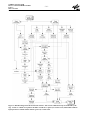
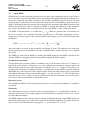
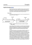
The sequence below also reflects the sequence of signal processing for the Extraction software.
This is illustrated by the data flow diagram of the Extraction software in Figure 1.
Conversion to Engineering units and time correlation (OP)
Calculate orbit and timing information and convert raw housekeeping data into physical quantities
(e.g. optical bench temperatures).
Calculate Geolocaltion (OP)
In the geolocation processing, the instrument scan angle and time information is converted to geographical coordinates, and the solar illumination condition is determined. This relies heavily on
the use of ESA’s Orbit Propagator, whose routines will not be explained in detail here.
Calculate Dark Signal (OP)
The algorithms describe how to use the Dark Measurements to derive calibration constants for
FPN and Leakage Current correction. Output to the calibration database is a set of dark signal
spectra for different integration times.
Apply Dark Signal (OP, E)
Subtract the correct dark signal spectrum from the measured spectrum.
Correction for FPA noise (OP, E)
Applies a correction factor for interference from the Peltier coolers on the Focal Plane Assembly.
Calculate PPG (OP)
Calculates from the LED calibration data the PPG (detector pixel-to-pixel gain), as the ratio of the
measured LED spectrum and the smoothed spectrum (smoothing using a triangular convolution
kernel of 5 pixels basewidth).
Apply PPG (OP, E)
Applies the calibration constants for PPG to the measurement spectrum.
Calculate Spectral Calibration Parameters (OP)
All algorithms listed above are applied to detector signals without need of knowledge of the precise wavelength of each pixel. This changes for the algorithms which follow, which need wavelength information in order to use the correct calibration constants. The algorithms described here
provide this wavelength calibration, using information from the internal spectral lamp and from
the Fraunhofer line structure in the solar calibration spectra.
- 15 -
GOME Extraction SUM
Doc.No.: ER-SUM-DLR-GO-0045
Issue: 3
Date: 14.12.04
Apply Spectral Calibration Parameters (OP, E)
Calculates for each detector pixel its wavelength [nm] from the spectral calibration parameters.
Determine PMD out-of-band Straylight (OP)
From solar calibration measurements, the measured PMD signal is compared to the expected signal calculated from the channel array intensity, and the ratio of the two is stored as so-called “Qfactor” in the calibration database.
Apply Straylight Correction (OP, E)
Uses pre-flight straylight characteristics (uniform straylight fraction and ghost intensites/widths)
to calculate the straylight spectrum and subtracts it from the measurements.
Apply BSDF (OP, E)
Uses measurements of the Sun over the diffuser to calculate a (daily) Sun Mean Reference spectrum, where the irradiance is calibrated via the BSDF function of the diffuser (OP). The application of BSDF is also performed in the radiometric calibration of science measurements of the Sun
( E).
Apply Radiance Response (E)
Perform the absolute radiometric calibration of the detector signals, including the calculation of
the radiometric accuracy. Optionally a Sun-normalised spectrum (the reflectivity) is calculated.
Determine Fractional Polarisation Values (OP)
Calculates the Fractional Polarisation Values at 7 wavelengths over the GOME range from the
ratio of PMD to channel signals, from the ratio of 2 overlapping channel signals, or from singlescatter theory (at 300 nm).
Apply Polarisation Correction (E)
The 7 Fractional Polarisation Values are interpolated to wavelength (OP, E). This is partly done
using modified spline interpolation (Akima), partly using a parameterisation of the polarisation
curve in the UV. From the interpolated polarisation values, a polarisation correction factor is
derived for and applied to each channel array detector pixel of the Earth-shine measurements (E).
Quality Flagging (OP)
Several data quality flags are written to the Level 1b product, e.g. for signal detection limit, saturated pixels, sun-glint conditions.
Calculation of errors (OP, E)
Calculates the accuracy errors on Keydata functions and on fractional polarisation, and the accuracy and precision errors on the Sun Mean Reference spectrum (OP). Calculates the precision of
the measured spectrum, and its accuracy, using errors on keydata and fractional polarisation from
the Level 1 product (E).
GOME Extraction SUM
Doc.No.: ER-SUM-DLR-GO-0045
Issue: 3
Date: 14.12.04
- 16 -
Figure 1: Data flow diagram of the Extraction software. The various calibration steps are indicated by the
tags -LAFS etc. which correspond to the filter used in the -c option (see Section 3.3.5). Dotted lines indicate
input parameters which remain valid for (parts of) a whole orbit.
- 17 -
GOME Extraction SUM
Doc.No.: ER-SUM-DLR-GO-0045
Issue: 3
Date: 14.12.04
3 Instructions for use
3.1
Installation
The extraction software comes on the product CD-ROM as a set of C routines in the directory
/programs/gdp01_ex
The extraction programme can be compiled from this directory using the statement
cc *.c -o gdp01_ex -lm
where cc is an ANSI C compiler, and gdp01_ex is the [default] name of the extraction program
for Level 1 data.
For full information, read the file readme_1st.txt in the root directory of the CD-ROM.
If you have already a version of gdp01_ex installed, and want to check if this is the latest version
available, then check the file with release history /docs/release_l01.txt
or run the program using the -i option (see Section 3.3).
If you are using an older version of the extractor, or if you are using a new version with older
Level 1 data, you may get the following warning message on screen when running the software:
**********************************************************
** WARNING: The software version used to generate the
**
**
Level 1 product (1.00 ) is different to the **
**
version of the extraction programme (1.40 ) **
**********************************************************
This warning is only important, if the format of the Level 1 product has changed. If there was no
format change between the two versions, this warning can be ignored. See the release notes for
format changes. Up to the moment of writing (version 2.20) no format change has taken place.
GOME Extraction SUM
Doc.No.: ER-SUM-DLR-GO-0045
Issue: 3
Date: 14.12.04
3.2
3.2.1
- 18 -
Standard Level 1 Extraction
Earth-shine Radiance
The default command for obtaining extracted Level 1 data in the form of calibrated Earth-shine
radiance spectra is
gdp01_ex
input_file
output_file
where input_file is a Level 1 product file.
The ASCII output with calibrated radiances will be written to file output_file.el1
where the extension .el1 denotes Earth-shine Level 1 data. Additionally, a file gdp01_ex.err
is generated, which describes the errors, if any, which occurred during program execution (this
file is appended, not newly created, after each run of the program).
The input Level 1 product files are stored on the CD-ROM in the directory \products
or on the ftp server ftp-ops.de.envisat.esa.int ; see file readme_1st.txt for further navigation on this site.
They have as default the extension .lv1
The output ASCII file of this default extraction contains header information (which calibrations
were applied, the physical units of the data, orbit number, orbit propagation data), the calibrated
Sun Reference Spectrum and, for each ground pixel of Earth-shine data, Sun-normalised PMD
values and for each spectral Band the spectral radiances and their errors.
The detailed format description can be found in the Product Specification Document (PSD) which
is contained on the CD-ROM or on the ftp server as acrobat .pdf file: \docs\PSD.pdf
3.2.2
Sun, Moon Observations
Apart from the Earth-shine observations obtained during normal scanning mode, there are at regular intervals also observations made of the Sun and the Moon. These observations can be
extracted from the data product using the -s or -m flags.
Solar observations are extracted using the command
gdp01_ex -s
input_file
output_file
where input_file is a Level 1 product file.
The ASCII output with calibrated irradiances will be written to file output_file.sl1
where the extension .sl1 denotes Sun-shine Level 1 data.
Lunar observations are extracted using the command
gdp01_ex -m
input_file
output_file
where input_file is a Level 1 product file.
The ASCII output with calibrated radiances will be written to file output_file.ml1
where the extension .ml1 denotes Moon-shine Level 1 data. Note that the calibrated radiance in
this case is not corrected for the slit filling factor which depends on the Moon’s phase and the
position of the GOME slit over the Lunar surface.
Note that only a small fraction of all Level 1 product files contains Sun or Moon observations. To
check whether or not a particular product file contains such observations, the contents of the file
can be examined (output to screen) using the command (see Section 3.3.1)
gdp01_ex -i input_file
GOME Extraction SUM
Doc.No.: ER-SUM-DLR-GO-0045
Issue: 3
Date: 14.12.04
- 19 -
3.3
Special Options
A large number of possibilities exists to configure the execution/output of the Extractor. In the following we will separate the options into several classes:
1.
2.
3.
4.
5.
options to obtain product information
options to steer the output
options to select a subset of data
options for scientific post-processing
options to perform/omit calibration steps
Options from the last 4 classes can be combined with each other.
Following the UNIX syntax, the extraction sofware can be called with flags −? to implement
these options. The general syntax is given by
gdp01_ex flag1 [param1_1] [param1_2] flag2 [param2_1] [param2_2]
... flagn [paramn_1] [paramn_2]
input_file output_file
where input_file is a Level 1 product file (default extension .lv1), and the output file gets an
extension .el1, .sl1, or .ml1 added depending on the type of observation (see Section 3.2).
In the following subsections we list the various options with program call using their flag, their
parameters if any, and we provide a short description of the actions taken.
For more information on the calibration steps, the reader is referred to Section 4.
3.3.1
Options to obtain product information
• general product information
gdp01_ex -i input_file
This provides screen output of data from the Specific Product Header (see [G4] ) such as
- GDP Software Version (Operational processor, not Extractor)
- Pre-flight Calibration Key Data Version (see also Section 4.1)
- Time Correlation Information (e.g. orbit number, UTC)
plus a summary of measurements on the file such as
- Time coverage of measurements
- Number of Earthshine Measurement Pixels
- Number of Sun Measurements
- Number of Moon Measurements
the latter two are usually 0 (i.e. no such measurementes performed in this orbit)
• geolocation information
gdp01_ex -g input_file
This provides screen output of the geolocation. For each ground pixel in the input file, it writes
the ‘Subset Counter’ from the ‘Earthshine Ground Pixel’ structure (see [G4] , this counter is
0,1,2,3 for East,Nadir,West,Backscan pixels) and the ‘4 corner and centre coordinates’ (latitude and longitude) from the ‘Geolocation Record 1’ structure (see [G4] ).
• selected product information
gdp12_ex -q input_file output_file
GOME Extraction SUM
Doc.No.: ER-SUM-DLR-GO-0045
Issue: 3
Date: 14.12.04
- 20 -
This prints selected data from the product into a file output_file.qa1 . This data is used
by DLR-DFD internally for quality assurance purposes, and is not further discussed here.
• write additional polarisation data and calibration data
gdp01_ex -w input_file output_file
In addition to the regular level 1 data in the file output_file.el1 [.sl1, .ml1]
this creates two files output_file.pcd and output_file.fcd
The .pcd file contains information from the ‘Pixel-specific Calibration Data’ structure (see
[G4] ), in particular it provides for each ground pixel the following (in order of appearance):
- pointer to the spectral parameters and leakage parameters on the .fcd file to be used for
spectral calibration and dark signal correction of this ground pixel.
- 7 polarisation fractions for PMDs 1,2,3, overlaps 1/2, 2/3, 3/4, p7 (=single scatter value
@300nm at centre of ground pixel) for the integration time of bands 1b-4 plus a value of p7
for the ground pixel centre over the last 1.5 second; given as array with effective wavelength,
p value, error on p value. In addition the value of the single scatter polarisation angle χ (see
Section 4.9) in radian units is given.
Note that the numbering of ground pixels on the .pcd file starts at pixel 0, whereas the numbering in the .el1 file starts at pixel 1; the pixel number on the .pcd is thus always 1 less than the
number of the same ground pixel on the .el1 file.
The .fcd file is the ASCII output of the ‘Fixed Calibration Data’ structure (see [G4] ) which
contains amongst others the following:
- band configuration i.e. start and end pixel of the 6 science bands and the 4 ‘straylight’ bands
- PPG parameters (see Section 4.4)
- dark signal parameters and spectral calibration parameters (both are indexed as function of
temperature; the relation of index to temperature is not visible in the Level 1 product, but
the index to be used for each measurement is visible in the .pcd file)
- Sun Reference spectrum units of BU.sr/s and corresponding PMD values
- radiance response function and polarisation sensitivity η on the wavelength grid of the SMR
(indexed as function of channel and as function of scan angle; the relation of index to scan
angle is not directly visible in the Level 1 product, but for the Earthshine measurements they
can be recovered by comparing the viewing angle of the ground pixel centre to the index in
the ‘Spectral Band Record’ structure (see [G4] ); however this structure is not written to any
ASCII output by the extractor)
For more detailed inforemation see the Product Specification Document [G4].
3.3.2
Options to steer the output
• write a separate file for each ground pixel
gdp01_ex -d input_file output_file
This splits (divides) the output for each ground pixel in a separate file
output_file_nnnn.el1
where nnnn is the number of the ground pixel (e.g. 0059 for ground pixel 59 in the level 1
product). Each file has the formatting of the standard ASCII output, in particular each file has
its own Solar Reference Spectrum before the start of Earthshine data. Usually this -d option
is used in connection with the -p option (Section 3.3.3) to limit the amount of output files.
- 21 -
GOME Extraction SUM
Doc.No.: ER-SUM-DLR-GO-0045
Issue: 3
Date: 14.12.04
• write a separate file for each ground pixel without Solar Reference Spectrum
gdp01_ex -n input_file output_file
This option is similar to the -d option, i.e. splits the output for each ground pixel in a separate
file output_file_nnnn.el1 (where nnnn is the number of the ground pixel), but the
Solar Reference Spectrum is omitted on each file. Instead, the Solar Reference Spectrum is
written on a separate file output_file.sun
• write the output in HDF format
gdp01_ex -h input_file output_file
This option is to be implemented in a future version of the software.
3.3.3
Options to select a subset of data
• extract only selected spectral bands
gdp01_ex -b b_filter input_file output_file
This provides an option to extract any combination of spectral bands. In addition to the regular
6 bands (1a, 1b, 2a, 2b, 3, 4) also the ‘blind’ band (the first 49 pixels of channel 1) and the
‘straylight’ bands (50 pixels directly before band 1a and 2a, and directly after band 1b) can be
extracted. Selection is via a character string b_filter which consits of 10 flags which are
either ‘y’ to enable selection or ‘n’ to disable selection.
The sequence is for bands 1a, 1b, 2a, 2b, 3, 4, blind 1a, stray 1a, stray 1b, stray 2a respecitvely.
For example: the default value in the extractor (science bands only) is b_filter =
yyyyyynnnn ; extracting channels 1 and 2 completely has b_filter = yyyynnyyyy .
If you wish to extract PMD signals only, set b_filter = “ “ .
• extract only ground pixels selected via pixel number
gdp01_ex -p p_first p_last input_file output_file
This selects only the ground pixels from (and including) pixel number p_first to (and
including) pixel number p_last. If only 1 pixel is to be extracted, set p_first equal to
p_last.
• extract only ground pixels selected via coordinates
gdp01_ex -r lat_ul lon_ul lat_lr lon_lr
input_file output_file
This extracts all pixels whose centres lie within a rectangle with upper left corner coordinates
(lat_ul, lon_ul) and lower right corner coordinates (lat_lr, lon_lr). The
coordinates are given as (latitude, longitude) in degrees. The range for latitude is from −90 to
+90 degrees, the range for longitude is from 0 to 360 degrees.
Example: to extract all pixels over the north pole down to 70 degrees latitude use the command
‘gdp01_ex -r 90. 0. 70. 360. input.lv1 output’.
• extract only ground pixels selected via time
gdp01_ex -t t_first t_last input_file output_file
This is similar to the -p option, except that pixels are not selected according to pixel number,
but according to measurement (readout) time. The time tags t_first, t_last are character strings formatted as DD-MMM-YYYY_HH:MM:SS.m where DD is day of the month, MMM
are the first 3 characters of the name of the month, etc.
GOME Extraction SUM
Doc.No.: ER-SUM-DLR-GO-0045
Issue: 3
Date: 14.12.04
- 22 -
Example to extract 20 seconds of data near 11 o’clock on April 1st 1996:
‘gdp01_ex -t 01-APR-1996_11:04:35.3 01-APR-1996_11:04:55.3 input.lv1
output’.
This option cannot be used in combination with the -p option.
• extract only ground pixels selected via pixel type (East, centre etc.)
gdp01_ex -x x_filter input_file output_file
This allows to extract only ground pixels at one position in the scan pattern: ‘East’, ‘centre’,
‘West’, ‘backscan’ (note that ‘East’ and ‘West’ only give the correct compass directions at the
descending [sun-lit] part of the orbit; on the ascending part it is just the other way around).
Selection is via a character string x_filter which consists of 4 flags which are either ‘y’ to
enable selection or ‘n’ to disable selection (like in the -b option). The flags are in sequence of
‘East’, ‘centre’, ‘West’, ‘backscan’, corresponding to the ‘pixel types’ 0,1,2,3 on the Level 1
product.
For example: the default value in the extractor (all pixel types) is x_filter = yyyy ;
extracting all but the backscan pixels is via x_filter = yyyn .
3.3.4
Options for scientific post-processing
• extract ‘albedo’s instead of radiances
gdp01_ex -a input_file output_file
The Earthshine radiances are divided by the Solar Reference Spectrum, after regridding of the
Solar spectrum to the wavelengths of the Earthshine spectra (Akima interoplation in wavelegth). Currently, no correction is made for Doppler shift of the solar observation (which is
below 1/10th of a detector pixel, but nevertheless neglecting this can introduce high-frequency
‘noise’ on the few percent level). Therefore, this option shall only be used in applications
where no high spectral resolution is required.
• smooth out radiance jumps
gdp01_ex -j input_file output_file
The detector arrays of GOME were designed for serial readout, such that the last pixel of the
array is read out 0.09375 seconds later than the first. When GOME is scanning over an inhomogeneous ground scene (e.g. broken clouds) the variation of upwelling radiance with time is
reflected in a variation of intensity depending on read-out time; the ground-scene inhomogenity is aliased in the spectrum (this effect is denoted as ‘spatial aliasing’). Such aliasing is often
visible as a jump in radiance between two detectors (e.g. the last pixels of channel 3 record the
same wavelengths as the first pixels in channel 4, but at an integration time which is shifted by
~0.09 seconds - although they should record the same intensity over a homogeneous scene
there may be a radiance ‘jump’ if intensity varies with time). Using information from the
PMDs, which are read out every 0.09375 seconds synchronised with detector pixel 1, a correction can be applied to re-normalise all spectral intensities to the intensity measured at the integration time of pixel 1 of the arrays [R8] - this is also the time for which the geolocation is
defined (note: pixel number 1024 is read 93.75 ms before pixel 1).
Note that this option adjusts only the absolute radiance levels; it cannot correct for the spectral
changes in absorption line depth or Ring effect with changing ground scene. Also, it can correct only a linear trend. The scientific usefulness of this option is therefore a matter of debate.
- 23 -
GOME Extraction SUM
Doc.No.: ER-SUM-DLR-GO-0045
Issue: 3
Date: 14.12.04
• correct degradation in radiance response
gdp01_ex -e deg_par_file input_file output_file
This option is implemented from version 2.00 of the software. A description of this correction,
together with the most recent file with degradation parameters deg_par_file will be put
on the DLR/DFD WWW server under http://wdc.dlr.de/sensors/gome (follow
the link to “Data describing Instrument Degradation” and “Degradation files”). It is intended to
update the file every 3 months.
• correct BSDF asymmetry
gdp01_ex -f deg_par_file input_file output_file
This option has been implemented from version 2.00 of the software. The parameters for correction are on the file with degradation parameters deg_par_file (see above under ‘correct degradation in radiance response’). Since version 2.30 of the software, the correction
method has been changed, and a different parametrisation is used. Versions of
deg_par_file lower than 2.0 are not compatible with the new method, but the newer file
still contains the old parameters so that older versions of the software still run.
The -f option corrects for a seasonal variation in the Sun spectra due to an asymmetry in the
BSDF of the diffuser, using a correction which is smooth in wavelength. This is the default
correction to be applied. As experimental option, which is currently not recommended, one can
instead use the same syntax with -u instead of -f (since software version 2.30). This will
apply a correction which contains spectral features on the BSDF for channels 1, 3, and 4.
3.3.5
Options to perform/omit calibration steps
• omit cross-correlation of solar spectrum
gdp01_ex -k input_file output_file
This option is implemented from version 2.20 of the software. As default, the spectral calibration of the SMR is from version 2.20 onwards corrected in the extraction software by crosscorrelation to a theoretical solar spectrum (see [G3] for detailed description). This time-consuming step can be switched off using the -k switch, if a high spectral accuracy is not needed.
• apply only selected calibration steps
These options shall not be used by the normal user of GOME level 1 data.
Apply the options in this section only if you are an advanced user who wants to study special
effects (e.g. check of dark signal and straylight subtraction in the ‘straylight bands), or if you have
a good reason to omit certain calibrations such as polarisation correction or radiance response calibration.
The generic command for applying calibration is
gdp01_ex -c c_filter
input_file output_file
where c_filter is a character string with for each calibration step a single key character:
L=Leakage, A=FPA, F=Fixed, S=Straylight, N=Normalize, B=BSDF, P=Polarization, I=Intensity, U=Unit_Conversion (details below).
The order of these calibrations shall not be changed.
GOME Extraction SUM
Doc.No.: ER-SUM-DLR-GO-0045
Issue: 3
Date: 14.12.04
- 24 -
The default extraction has c_filter = LAFSNPIU for Earthshine data, c_filter =
LAFSNBIU for Sunshine data, and c_filter = LAFSNIU for Moonshine data.
For the 4 ‘blind’ and ‘straylight’ bands, only the calibrations LAFSN can be succesfully applied.
The other calibrations yield zero signals because the corresponding keydata are missing.
The Solar Reference spectrum on the Level 1 product has already the calibrations LFSNB applied
(the A calibration is omitted because of the small integration time which makes the FPA component small). The extractor always adds the calibration I. This implies that even when Earthshine
data are extracted with e.g. c_filter = L, the accompanying Solar Reference spectrum will
still have c_filter = LFSNBI. Only the U calibration has effect on the Solar Reference.
The PMD values of the Sun Reference are corrected for Leakage only.
If no calibration is to be applied (i.e. extract level 0 data), use c_filter = ‘’ .
For the real hackers amongst you: note that the calibrations are always executed on the Level 1 product. For example,
it is not possible to perform certain calibration steps using the extractor, then perform a calibration on your own on
the ASCII file, and then run the extractor on the ASCII file to perform more calibration steps. Therefore, if you would
wish to change calibrations (e.g. to subtract a different dark signal background), you would have to overwrite the corresponding fields in the ‘Fixed Calibration Data’ structure (see [G4] ) on the Level 1 product. For a certain ground
pixel, the pointers to the fields actually used (there may be more fields depending on temperature etc.) can be found
from examining the .pcd file. See option -w in Section 3.3.1 .
An overview of calibration steps follows below; the calibration steps are performed in the
sequence as given. For more information on the background of the calibration, the reader is
referred to Section 4.
• Leakage
The measured level 0 spectra are corrected for the dark signal by subtraction of a ‘Dark Spectrum’ (which for each detector pixel is a combination of readout fixed-pattern noise and leakage current). See Section 4.2
• FPA
Correct channel 1 for cross-talk from the Peltier coolers in the Focal Plane Assembly (FPA).
See Section 4.3
• Fixed
Correct signals for pixel-to-pixel (fixed pattern) variations in the instrument response. See Section 4.4
• Straylight
Correct signals for straylight (uniform and spectral ghosts components). See Section 4.6
• Normalize
Normalise the signals to 1 second detector integration time (convert from BU to BU/s) by
dividing the signal in each band by the integration time of that band. PMD signals are not
affected.
• BSDF
Divide signals from Sun measurements by the BSDF of the diffuser to convert the radiance
measured by the spectrometer into irradiance (in this step the irradiance is not yet absolutely
calibrated; that occurs in the ‘Intensity’ calibration below). See Section 4.7
• Polarization
Interpolate the polarisation fractions p (up to 7 points; from theory and from the measured
polarisation points of PMDs and overlap regions if available) to the wavelength of each detec-
- 25 -
GOME Extraction SUM
Doc.No.: ER-SUM-DLR-GO-0045
Issue: 3
Date: 14.12.04
tor pixel. Multiply the signal of each pixel with the polarisation correction factor derived from
this interpolated p-value and calibration key data for the instrument’s polarisation sensitivity.
See Section 4.9. This applies to Earthshine data only.
• Intensity
Perform the absolute radiance calibration. For earthshine and moonshine signals the conversion is from BU/s to Watt/(s.cm2.sr.nm), for sunshine from BU.sr/s to Watt/(s.cm2.nm). For
earthshine, the PMDs are normalised to the PMD signal of the Solar Reference spectrum and
divided by the polarisation fraction, to obtain an ‘unpolarised’ reflectivity. See Section 4.8
• Unit_Conversion
Convert units of Watt/... to photons/...
GOME Extraction SUM
Doc.No.: ER-SUM-DLR-GO-0045
Issue: 3
Date: 14.12.04
- 26 -
4 Background Information on Algorithms
4.1
Overview of Calibration Procedures
Calibration of the instrument is performed on 3 different levels:
1. Onground Calibration:
determines the instrument response to calibrated radiance and irradiance sources as function
of wavelength and scan mirror angles; determines the straylight properties of the instrument;
provides preliminary calibration of wavelength and dark signal.
2. Level 0 to 1b Processing of Calibration Constants:
Calibration constants which can be directly derived from measurements using on-board calbration sources are determined during the operational Level 0 to 1 processing. This comprises
dark signal measurements on the night side of each orbit, and at regular intervals wavelength
calibration using the SLS measurements and PPG calibration using the LED measurements.
3. Correction of degradation:
due to degradation (mostly damaging by UV light) in optical components or detectors, the calibration constants for radiance and irradiance will change in time. This degradation cannot be
derived from on-board calibration sources and has to be modelled externally from the data
processor, by scientific analysis of time sequences of solar, lunar or earth-shine observations.
4.1.1
Onground Calibration
The onground calibration has been performed by TPD/TNO. The output of the on-ground calibration relevant to the operational Level 0 to 1 processing, is a data set containing the so-called ‘Calibration Key Data’.
For various reasons the orginal Key Data set had to be adjusted from the on-ground situation to
the in-flight situation; mostly due to air-vacuum wavelength shifts and outgassing of optical coatings. This has resulted in several updates of the Key Data set by TPD - their most recent work
resulting in Version 8 of the Key Data.
At the moment of writing a contract has been given out to SRON and DLR-DFD to improve on
this Key Data set, using the time sequence of science measurements now available, and to characterise the time-dependence of calibration constants in-flight.
4.1.2
Level 0 to 1 Processing of Calibration Constants
Dark signal from the channel array detectors and from the PMDs is measured at each dark side of
the orbit. Dark signal has a fixed component, the so-called fixed-pattern noise (FPN), as well as a
component due to charge leaking which increases linearly with detector exposure time. Therefore,
a series of dark spectra is taken at each night side of the orbit. All integration time patterns (i.e.
combinations of IT for the different detectors) which may occur in the science measurement are
covered. The dark spectra are included in a Calibration Database as function of integration time
pattern. For processing, the most recent applicable dark spectrum from the database is used.
Spectral calibration is performed at regular intervals (typically monthly) using the sharp emission
lines of an internal Pt/Cr-Ne hollow cathode lamp (the SLS). For each channel, a 3rd order (in
channels 1,2) or 4th order (in channels 3,4) polynomial is fitted to the spectral line positions to
obtain wavelength as a function of pixel number.
Since the SLS shows signs of degradation (with possible failure), an option is beinig implemented
to obtain a wavelength calibration from Solar observations, using the Fraunhofer lines in the Sun.
- 27 -
GOME Extraction SUM
Doc.No.: ER-SUM-DLR-GO-0045
Issue: 3
Date: 14.12.04
The wavelength calibration depends on the temperature of the optical bench. Therefore the polynomial calibration constants are stored in the Calibration Database as function of temperature, in
0.1 K intervals of temperature. For processing, the most recent applicable coefficients from the
database are used. The typical temperature variation over one orbit is ~1 K; the instrument starts
heating up as soon as it enters sunlight and it starts to cool down when entering the dark part of
the orbit.
Calibration measurements from Light Emitting Diodes (LEDs), which are placed close to the
detectors, are used for flat-fielding the spectra of each detector array. This comprises the calculation of pixel-to-pixel gain (PPG). The PPG calibration is also done only at regular (typically
monthly) intervals.
Daily observations of the Sun over a diffuser plate provides a solar reference which is used in the
calculation of the Earth-shine reflectivity spectra. The calibrated solar irradiance spectrum is output as measurement data on the product of the orbit containing the solar measurement; for subsequent orbits it is used as calibration data for reflectivity, until a new Sun is observed. This
calibration data is referred to as the Sun Reference spectrum or Sun Mean Reference (SMR).
4.1.3
Correction for degradation
The degradation of the instrument can be monitored by combining measurements from several
sources over a longer period in time. This is an off-line activity. The results have to be fed into the
data processor as additional calibration constants.
At the time of writing this research is still an on-going activity. Preliminary results have been
obtained for the Radiance Response function in combination with the BSDF [R10][R11]. Correction factors for these calibration constants can at present be applied in the Extraction Software
only (see Section 4.10).
At present no attempts are being made to correct for the etalon effect - a low-frequency spatial
(i.e. as function of pixel number) oscillation in detector response caused by a changing thickness
of ice deposits on the detector (see e.g. [R4]). For level 1 to 2 processing using the DOAS spectral
analysis method this effect is not significant, since it divides out of the ratio of earth-shine to solar
spectra.
GOME Extraction SUM
Doc.No.: ER-SUM-DLR-GO-0045
Issue: 3
Date: 14.12.04
4.2
- 28 -
Apply Dark Signal
The measured spectra are corrected for the dark signal by subtraction of a ‘Dark Spectrum’ which
for each detector pixel is a combination of readout fixed-pattern noise (FPN) and leakage current
(LC - this component increases linearly with detector integration time). In the present calibration
approach these two components are not separated (they used to be in the prototype version of the
processor; the ‘Dark Current & Noise Factor’ on the .pcd file still refers to this - these data are
obsolete).
The dark spectra (measured at each night side of the orbit) are stored in the calibration database as
function of temperature. The Level 0 to 1b processing takes the most recent values from the database for the temperatures encountered in the orbit, and writes these in the FCD record on the
Level 0 to 1b product. Each measurement on the product has an index which points to the applicable temperature. The temperatures themselves are not visible in the product - see also option -w
in Section 3.3.1
For the PMDs, the PMD zero offset is subtracted. These offsets are written on the FCD record just
above the channel detector data.
Directions for use
This calibration should always be applied in the Extractor.
Limitations
It is known that in orbit regions affected by cosmic particle bombardments (the South Atlantic
Anomaly), the real background signal will be higher than the usual dark signal. This has the effect
that within the SAA the dark signal is underestimated, whereas it is overestimated on orbits which
directly follow an orbit where the SAA was measured at the night side. It is also known that, due
to interference effects from the Peltier coolers, the real background signal may differ a little (plus
or minus) from the calibrated one: this effect is addressed in the next section on FPA correction.
- 29 -
4.3
GOME Extraction SUM
Doc.No.: ER-SUM-DLR-GO-0045
Issue: 3
Date: 14.12.04
Correction for FPA noise
Time series of the dark signal show a “noise” on the dark signal level which seems to be correlated to the voltage controlling the Peltier coolers on the Focal Plane Assembly [R9].
The correction is calculated as the Peltier output multiplied by a scaling factor. This scaling factor
is in fact dependent on the history of cooler switches, and thus should ideally be calculated anew
for each orbit, using all measurements in that orbit. However, this conflicts with the GDP architectural requirement that each ground pixel shall be independently processable. Therefore the scaling
factor from one ‘typical’ orbit is used - the variation with orbit is expected to be ~10%.
The value of the Peltier output is for each readout calculated as a weighted average of the last 61
Peltier voltage readings. This weighting is equivalent to a filtering of the signal. The filter coefficients and the scaling factor are present in the FCD record on the Level 1b product.
The magnitude of the effect scales with integration time. Since it was regarded negligible for the
1.5 second integration times, the correction is only applied to band 1a.
Directions for use
This calibration should always be applied in the Extractor.
Limitations
The FPA correction is known to be not perfect; the typical reduction in FPA noise is a factor of ~5
but dark signal errors up to ± 7 BU remain (for 12 seconds integration time; the typical uncertainty
is ~3 BU).
GOME Extraction SUM
Doc.No.: ER-SUM-DLR-GO-0045
Issue: 3
Date: 14.12.04
4.4
- 30 -
Apply PPG
The PPG describes the differences in quantum efficiency between neighbouring detector pixels. It
is in principle contained in the instrument resonse function, but it is artificially separated from the
instrument response function during calibration for the following reason. If the wavelength calibration of the instrument changes due to whatever mechanism, the radiometric response function
of the instrument seen by a single detector pixel changes with it (this depends on wavelengthdependent transmission of lenses etc.). We have to re-interpolate the radiometric response to the
wavelength of the detector pixel to be calibrated, but if pixel-to-pixel variations in quantum efficiency are present, the quantum efficiency of one pixel would be transferred to that of another
pixel if the radiance response function were not corrected for PPG.
The radiance response function in the GOME calibration Keydata is corrected for PPG, and so
must be the detector signals before applying that function.
The PPG calibration data are stored in the form of (calibration) spectra in the calibration database.
The PPG spectrum from the calibration database is updated in regular (baseline: monthly) intervals, following a LED calibration measurement. The Level 0 to 1b processing takes the most
recent PPG values from the database and stores these in the FCD record on the Level 0 to 1b product.
The application of this calibration parameter consist of dividing each measured detector pixel by
the corresponding pixel in the PPG calibration spectrum from the Level 1 product.
The error on PPG correction is neglected in the calculation of the precision error.
Directions for use
This calibration should always be applied in the Extractor.
Limitations
None.
- 31 -
4.5
GOME Extraction SUM
Doc.No.: ER-SUM-DLR-GO-0045
Issue: 3
Date: 14.12.04
Apply Spectral Calibration Parameters
The main objective of the spectral calibration is to assign a wavelength value to each individual
GOME detector pixel.
In each channel, a polynomial has been determined which gives wavelength [nm] as function of
pixel number. The calibration parameters for spectral calibration are the coefficients of this polynomial. The order of the polynomial is not larger than 4.
Calibration polynomial coefficients are derived for different optical bench temperatures, for intervals of 0.1 K.
The polynomial coefficients are stored in the calibration database. The data are updated in regular
(baseline: monthly) intervals, following a spectral line lamp calibration measurement. The Level
0 to 1b processing takes the most recent values from the database for the temperatures encountered in the orbit, and stores these in the FCD record on the Level 0 to 1b product. Each measurement on the product has an index which points to the applicable temperature. The temperatures
themselves are not visible in the product.
In software version 2.00 a fixed correction is added to the polynomial coefficients. This correction
term (a constant for channels 1, 2 and a 4th order polynomial for channels 3,4) describes the
wavelength shift (averaged over the first 4 years in-orbit) between the GOME solar spectrum (calibrated with the lamp and corrected for Doppler shift) and the high-resolution solar spectrum of
Kurucz. This correction is applied in the operational processing to the spectral coefficients on the
Level 1b product and does not influence the Extractor.
In software version 2.20 a similar correction is now calculated in the Extractor, for the solar spectrum. However, this correction is not based on an average shift, but is calculated on the measured
spectrum using on-line cross-correlation with the Kurucz spectrum. This correction is applied as
default, but can be switched-off using the -k option in the Extractor.
Doppler shifts
The solar spectra will be doppler shifted due to the motion of the spacecraft in the direction of the
light source. These shifts vary from maximally 0.06 detector pixel in channels 1, 3 to maximally
0.1 detector pixel in channels 2, 4.
This does not in any way influence the wavelength calibration of the instrument as such; the
wavelength of each pixel for calibration parameters is given in the instrument reference frame, not
in the moving solar reference frame. Therefore, the wavelength calibration on the level 1b product
is in the instrument rest frame only.
The user must be aware of this and if necessary account for solar doppler shift himself.
The velocity of the spacecraft is around 7.6 km/s, the exact value is provided on the Level 1 product. The observation angle to the Sun is around 21 degree from the forward position, depending
on the time of the year. The exact solar azimuth angle w.r.t. spacecraft is provided with the Sun
measurements (not the Sun Reference spectrum) on the Level 1 product (as far as it contains Sun
measurements).
Directions for use
The calibration is always applied automatically. The time-consuming cross-correlation on the
solar spectrum may be switched off using the -k switch, if a high spectral accuracy is not needed.
GOME Extraction SUM
Doc.No.: ER-SUM-DLR-GO-0045
Issue: 3
Date: 14.12.04
- 32 -
Limitations
Wavelength calibration errors are typically 0.05 of a detector pixel. At the short wavelength side
of channel 3 the error may be larger, due to the scarcety of lamp lines there. Mind the solar doppler shift mentioned above.
- 33 -
4.6
GOME Extraction SUM
Doc.No.: ER-SUM-DLR-GO-0045
Issue: 3
Date: 14.12.04
Apply Straylight Correction
This comprises subtracting the calculated amount of straylight per pixel from the measurement.
The calibration keydata contain for each channel uniform straylight factors (straylight scales with
total intensity in the channel) and spectral ghost characteristics. The latter consist of the symmetry/asymmetry pixel, the ghost intensity, and the ghost spectral width. These data are present in
the FCD record on the Level 1b product as direct copy of the calibration keydata.
The straylight is calculated on a per channel basis. In the bands where at a certain readout not the
whole channel is available, the straylight correction is only performed using the signals from the
available datapoints: missing data are set to 0 (no attempt is made to estimate the intensity in the
missing part of the channel). This can currently only happen for band 1b when band 1a is still
integrating. It is not considered a problem since the total intensity in band 1a is small compared to
that in band 1b.
The error on the signal due to errors in straylight subtraction is mainly a precision error. This error
is neglected in the precision error on the Level 1b data (see Section 4.11).
The so-called ‘PMD straylight’ (the factor Q in Eq.45 in [G3]) is not corrected, neither for earthshine PMDs nor for the PMDs of the Sun Reference spectrum. This is a multiplicative term which
falls out of the equation for the earthshine PMD reflectivities - the only quantity used in level 1 to
2 processing. PMD straylight has been taken into account for the calculation of polarisation fraction in the operational Level 0 to 1 processing, but is nowhere explicitly visible on the Level 1
product.
Directions for use
It is recommended to apply this calibration in the Extractor.
Limitations
The Calibration Keydata for straylight are probably not more accurate than ~10%; this uncertainty
is not well characterised.
GOME Extraction SUM
Doc.No.: ER-SUM-DLR-GO-0045
Issue: 3
Date: 14.12.04
4.7
- 34 -
Apply BSDF
GOME takes at regular intervals (typically once per day) solar calibration spectra, in the sunrise
part of the orbit. An on-board diffuser can be switched into the lightpath during sun calibration, to
scatter the collimated solar light (irradiance) into a diffuse (radiance) beam. Obviously, the solar
spectrum thus recorded must be corrected for the characteristics of this diffuser. That correction is
made by dividing the detector signals of the measured solar spectrum by the BSDF function of the
diffuser (more precisely, what we calculate as ’BSDF’ is actually the reflectivity of the calibration
unit, which corresponds to one viewing direction out of the BSDF’s 2-dim ’reflectivity space’).
The BSDF is characterised by 11 coefficients c0 ... c10 which are present in the FCD structure of
the Level 1 product. It is calculated from these coefficients as a 7th degree polynomial in wavelength with correction terms for the Azimuth and Elevation angles (Az, Ele) of the Sun beam onto
the diffuser:
7
2
BSDF = c 0 ⋅ ( 1 + c 1 ⋅ Az ) ⋅ ( 1 + c 2 ⋅ Ele ) ⋅
∑
k=0
λ
c ( k + 3 ) ⋅ ---------
500
k
where the angles are given in degree and the wavelength λ in nm. The angles are for each solar
measurement given in the Sun/Moon Specific Calibration Data structure on the Level 1 product
(see [G4]).
The PMDs are corrected for BSDF by dividing the PMD signals by the BSDF evaluated at the
effective PMD wavelength (specified on the product together with the signals).
Sun Reference spectrum
The Sun Reference spectrum, which is included in the FCD structure of the Level 1 product, is
calculated as the average of all spectra in a solar calibration measurement sequence which are
fully inside the field-of-view of the instrument’s irradiance port (+/- 1.5 degree in elevation), corrected for the instrument’s irradiance response - a combination of the radiance response function
and BSDF (the various spectra of this sequence differ from each other because they are measured
with slightly different elevation and azimuth angles) - see also Section 3.3.5 . The Sun Reference
spectrum on the Level 1 product is always obtained from the measurements on a previous orbit,
not from the solar measurements on the product itself.
Directions for use
This calibration shall be used in the Extractor whenever a conversion from radiance to irradiance
is required.
Limitations
The calibration can only be performed on Sun measurements, i.e. in combination with the -s
option in the Extractor. It is already applied to the Sun Reference spectrum on the Level 1 product; this cannot be undone.
The BSDF calibration does not take into account the azimuth asymmetry of the BSDF which was
found after analysing 4 years of data. The correction for azimuth asymmetry is possible from software version 2.00 in the Extractor, using option -f (see Sections 3.3.4, 4.10).
- 35 -
4.8
GOME Extraction SUM
Doc.No.: ER-SUM-DLR-GO-0045
Issue: 3
Date: 14.12.04
Apply Radiance Response
The application of the radiance response is simply a division of the observational signals (after
dark current, PPG, and straylight correction) by the radiance response function. This function is
provided in the FCD structure of the Level 1 product; per detector pixel one value is specified for
each scan mirror angle and for each channel - characterised by the same index as for the polarisation sensitivity η, see Section 3.3.1 under option -w.
Before the division by the radiance response function is made, it is interpolated from the wavelength grid of the SMR to the wavelength grid of the Earth-shine spectrum.
The radiance response function on the FCD file is in fact composed of 3 calibration Keydata functions: the radiance response for nadir (‘RadResp’), the scan mirror dependence w.r.t. nadir
(‘SM_DEP’) and a function (‘f2’) which was meant to describe the temperature dependence in
the overlap region (for the latter now always the function for 6.5° C is used).
Optionally (see Section 3.3.4 under option -a) the Sun-normalised radiance or Reflectivity can be
calculated from the calibrated radiance (S_cal) as:
R λ = S_cal λ ⁄ SM R λ
Before the division by the Sun Reference spectrum (SMR) is made, the SMR is interpolated to the
wavelength grid of the Earth-shine spectrum.
Directions for use
This calibration should always be applied in the Extractor if absolutely calibrated radiances are
required. If a relative calibration is sufficient, this calibration is not required. However, note that in
wavelength regions where the radiance response function has sharp features, not correcting for
radiance response implies that the uncalibrated spectrum has sharp features as well (which may
disturb e.g. a DOAS fit).
Limitations
It is known that especially in channel 3 the on-ground calibration determination is not very accurate due to outgassing problems with a dichroic. This problem is still present for Keydata version
8; work for improvement is in progress.
Errors due to the etalon effect [R4] are not corrected. This should not be a problem for sun-normalised spectra, but an etalon structure with amplitudes of up to a few percent may be visible in
radiance (Earth, Moon) or irradiance (Sun) spectra.
In Keydata version 8, noise can be seen on the calibration parameter for radiance response. This
noise will be aliased into the calibrated radiance, and could adversely influence the pixel-to-pixel
precision of the measurements.
GOME Extraction SUM
Doc.No.: ER-SUM-DLR-GO-0045
Issue: 3
Date: 14.12.04
4.9
- 36 -
Apply polarisation correction
GOME is a polarisation sensitive instrument. The radiance response function described in the previous section calibrates the instrument assuming unpolarised input light. Therfore, a correction
factor must be applied which describes the ratio
( instrument throughput for the actual input polarisation ) / ( throughput for unpolarised light ).
This correction needs the polarisation sensitivity of the instrument and a characterisation of the
atmospheric polarisation.
The polarisation sensitivity of the instrument ( η , called Eta_Omega on the .fcd file) is provided
in the FCD structure of the Level 1 product; per detector pixel one value is specified for each scan
mirror angle - characterised by the same index as for the Radiance Response, see Section 3.3.1
under option -w.
The atmospheric polarisation has been retrieved during the operational Level 0 to 1 processing.
The Level 1 product contains for each ground pixel in the ‘Pixel-specific Calibration Data’ structure (PCD, see Section 3.3.1 or [G4] ) a small array of fractional polarisation values at certain
well-spaced wavelengths across the GOME spectral range. Up to 7 points can be specified.
Three points come from the comparison of channel array signals with broad-band PMD signals
(in Figure 2 these are the filled circles at points P with index 1, 2, 3; the corresponding wavelengths λ1, λ2, λ3 are approximately 360 nm, 500 nm and 700 nm depending on the exact spectral
shape of the input spectrum). Three more points come from the channel overlap regions (in Figure 2 these are the open circles at points P with index 4, 5, 6 for overlaps between channels 1/2, 2/
3, 3/4; the corresponding wavelengths λ4, λ5, λ6 are at 312.5, 400, 600 nm approximately)
though these appear to be largely unuseable for various reasons (in which case they are set to a
number >99 at wavelength −1 in the PCD). The last ("theoretical") point (labelled [λ7, P7] in the
figure) comes from the Rayleigh single-scatter model simulation of polarisation in the Ultra Violet.
I
1
II
III
channel
P7
P1
P
P5
P2
P4
0
IV
P6
λ7 λ4 λ
300
325
λ1 λ5
λ2
400
λ6
600
Wavelength [nm]
Figure 2: Wavelength interplation of polarisation values
P3
λ3
800
- 37 -
GOME Extraction SUM
Doc.No.: ER-SUM-DLR-GO-0045
Issue: 3
Date: 14.12.04
The fractional polarisation values, p, give the fraction of light polarised along the direction of the
instrument slit; this is the quantity relevant to GOME calibration. The relation between p and
more widely used atmospheric parameters such as the Degree of Polarisation, P, and the polarisation angle, χ (defined w.r.t the plane through Nadir, instrument, and viewing direction), is given
by:
p = 0.5 ⋅ ( 1 – P ⋅ cos 2χ)
Before these polarisation values can be used for polarisation correction of the measured intensity,
they must be interpolated to the wavelengths of all detector pixels. The interpolation scheme is
based on simulations of the Degree of Polarisation, P, as function of wavelength. But since the
algorithm assumes a constant value for the polarisation angle χ as function of wavelength, the
same interpolation may be made on p as well.
Radiative transfer model calculations, including polarisation, have been performed by P. Stammes
(KNMI) to study the polarisation behaviour in the UV for application to the GOME instrument
[R5], [R7]. These simulations show that up to wavelength λ7 (300 nm), the degree of polarisation
P(λ) is virtually a constant, so there we set fractional polarisation equal to the theoretical singlescatter value at λ7. P(λ) then changes rapidly between λ7 and a value λ ( ≈ 325 nm), then shows
smooth behaviour into the visible (ca. 325-400 nm). Thereafter, P(λ) is a smooth slowly-varying
function of wavelength.
The interpolation of polarisation goes roughly as follows (for details see [G3]):
- constant shortward of wavelength λ7 ( ≈ 300 nm, pre-defined on the initialisation file)
- a parametrisation (see below) between λ7 and a pre-defined wavelength λ ( ≈ 325 nm)
- power law (continuity in value and in gradient) between λ and λ1 (if P4 present, else see below)
- Akima interpolation between λ1 and λ3 (this is basically a spline interpolation, but with
constraints to reduce overshoot)
- constant longward of λ3.
The critical region is 300-325 nm. An analytic function is required that mirrors the shape of simulated polarisation for all atmospheric scenarios. This function must have a turning point at the
theoretical point λ7, with parabolic fall-off behaviour near this point. The function must also show
exponential tail behaviour as λ tends towards λ . This role is fulfilled by the Generalised Distribution Function (GDF) constructed by R. Spurr for the GOME calibration [G3]:
w ⋅ exp ( – [ λ – λ 7 ] ⋅ β )
P ( λ ) = P ( λ ) + --------------------------------------------------------------2
{ 1 + exp ( – [ λ – λ 7 ] ⋅ β ) }
where { P , w, β} are parameters that characterise the GDF; they must be found to fit the given
interpolation points. If P4 is missing, which ususally is the case, then there are more parameters
than equations. In this case the GDF is connected directly to λ1 with continuity of the gradient
derived from Akima interpolation. However, if that gradient turns out to be positive then the GDF
cannot be connected directly and is connected instead with zero gradient to the point halfway
between λ and λ1 , and a parabolic connection (continuous in value and gradient) is made from
the halfway point to λ1.
GOME Extraction SUM
Doc.No.: ER-SUM-DLR-GO-0045
Issue: 3
Date: 14.12.04
- 38 -
The actually simulated polarisation shows a bit more complex behaviour, e.g. some residual structure of the O3 Huggins bands is visible in the polarisation (due to different airmasses in- and outside the absorption peaks with different depolarisation by aerosols), but the approximation above
was found accurate to better than 3% compared to the simulated polarisation values.
Once the interpolated fractional polarisation values have been calculated, the polarisation correction factor is given by
1 + ηi
1
c i = --- ⋅ --------------------------------------2 ( 1 – ηi ) ⋅ pi + ηi
where subscript i denotes detector pixel.
The errors on the polarisation correction factor are derived from the errors on the seven p values
on the Level 1 product, and from the errors on the calibration keydata for η. Errors due to the
interpolation of polarisation values is not taken into account.
The errors are added to the error on absolute radiometric response, not to the error on relative
radiometric (pixel-to-pixel) response.
Directions for use
This calibration should always be applied in the Extractor if absolutely calibrated radiances are
required. If a relative calibration is sufficient, this calibration is not required. However, note that in
wavelength regions where η has sharp features, not correcting for polarisation may imply that the
uncalibrated spectrum has sharp features as well (which may disturb e.g. a DOAS fit).
Limitations
It is known that especially in channel 3 the on-ground calibration determination of η was not very
accurate due to outgassing problems with a dichroic, leading to problems with polarisation correction. This problem is still present for Keydata version 8; work for improvement is in progress.
Errors in the determination of p, or in the wavelength interpolation of p may lead to undercorrected spectral features in the spectrum.
In Keydata version 8, noise can be seen on the calibration parameter η. This noise will be aliased
into the calibrated radiance, and could adversely influence the pixel-to-pixel precision of the
measurements for high values of the atmospheric polarisation.
No overlap point (at λ4, λ5, λ6) is currently being used in the wavelength interpolation, as their
reliability was judged to be too low due to the ‘radiance jump’ problem (see Section 3.3.4 under
option -j ).
- 39 -
4.10
GOME Extraction SUM
Doc.No.: ER-SUM-DLR-GO-0045
Issue: 3
Date: 14.12.04
Apply Degradation Parameters or azimuth asymmetry of the BSDF
In software version 2.00 an option -e has been added to the Extractor to correct the Radiance
Response function of the instrument for degradation of the optical components [R11]. The reason
that this is done in the Extractor and not in the operational processing is twofold: no change in
product format is needed (at the cost of having an additional file with Degradation Parameters),
and users can reprocess (a selection of) their old data themselves which avoids operational reprocessing and the distribution of the whole archived dataset to all users.
For the same reasons (product format/ reprocessing) a separate option -f corrects the solar spectra for an azimuth asymmetry of the BSDF, which was found after analysing almost 4 years of
data. This asymmetry is not really a degradation, but a seasonal effect which can be seen as a disturbance of the degradation curve [R10]. Since software version 2.30 an improved correction
method is used which also corrects the ‘sidelobes’ found on the BSDF [R13]. Like the previous
correction, this is a smooth function of wavelength. As discussed in [R13], there is also spectral
structure visible on the BSDF which could be described for channels 1, 3 and 4. This has experimentally been implemented in the software (option -u instead of -f).
The degradation of optical components does not only affect the Radiance Response function, but
also the calculation of the fractional polarisation values p (see Section 4.9). For PMDs 2 and 3 this
degradation was always more or less equalised by a self-calibration on the Sun which was initially
intended to correct straylight only. This self-calibration is from version 2.00 onwards also applied
to PMD 1.
Directions for use
It is recommended to apply the -e calibration in the Extractor (see Section 3.3.4) if a Radiance
Response calibration is also applied (Section 4.8).
For solar spectra: if also a BSDF correction is to be applied (Section 4.7) it is recommended to use
both the -e and the -f option. The use of the experimental -u option is not recommended.
Limitations
The degradation is modelled with a polynomial function only. Shifts in Etalon are not corrected.
An additional file with Degradation Parameters is needed (see Section 3.3.4 under option -e).
Software versions from 2.30 need a degradation file version of 2.00 or higher.
For Level 1 products generated before version 2.00 no correction is possible on the fractional
polarisation values p from PMD 1.
The PMD reflectances are not corrected. The influence of degradation is relatively small (and zero
for unpolarised input) since a normalisation with Sun observations is made.
GOME Extraction SUM
Doc.No.: ER-SUM-DLR-GO-0045
Issue: 3
Date: 14.12.04
4.11
- 40 -
Calculation of Errors
A distinction is made between accuracy errors and precision errors:
• The accuracy of a measurement is a measure of how close its result is to the true value.
• The precision of a measurement is a measure of how well its result has been determined, without reference to its agreement with the true value. Precision is therefore a measure of the reproducibility of the result, irrespective of e.g. a systematic deviation.
In the GOME level 1 context, as precision errors are taken the random errors due to shot noise,
electronic readout noise, and errors due to digitisation of the signal. As accuracy errors are taken
the precision error augmented for each calibration step with errors on the related calibration Keydata.
The precision error is on the Level 1 product expressed in absolute [radiance] units; on the level 1
ASCII output this is the 3rd column with data (the first two columns are wavelength and radiance).
The accuracy error is on the Level 1 product expressed in relative units, as ratio of accuracy errors
in absolute [radiance] units with the signal in absolute [radiance] units; on the level 1 ASCII output this is the 4th column with data.
- 41 -
GOME Extraction SUM
Doc.No.: ER-SUM-DLR-GO-0045
Issue: 3
Date: 14.12.04
5 Appendix: Version history
The most recent description of the version history can always be found on the distribution CD in
the file:
/docs/release_l01.txt
The majority of software changes reported in that file applies to the operational GDP processor,
and not to the extraction software. Changes in extraction software are explicitly mentioned as
such.
Changes in extraction software mentioned in the file are (up to the time of writing) are for clarity
seperately listed below:
/*-------------------------------------------------------------------------*\
**
**
**
GDP Level 0 to 1 - Release Notes
**
**
**
**
Author: Diego Loyola, DLR/DFD-AP
**
\*-------------------------------------------------------------------------*/
/*-------------------------------------------------------------------------*\
** Release 2.30
Tue Dec 14 16:31:52 MET 2004
\*-------------------------------------------------------------------------*/
o New functionality in the Extraction software:
Two new BSDF correction algorithms have been implemented : with smoothed
correction parameters using a polynomial in wavelength, and with
unsmoothed correction parameters read from the degradation-file.
/*-------------------------------------------------------------------------*\
** Release 2.20
Mon Apr 8 15:51:34 MET DST 2002
\*-------------------------------------------------------------------------*/
o New functionality in the Extraction software:
update spectral calibration of the Sun Mean Reference spectrum using
cross-correlation with a template spectrum; option ’-k’ disables this
feature.
o Optimize the test to reject Sun calibrations with improper illumination.
(ERS-2 EBM problem starting in 17th January 2001)
/*-------------------------------------------------------------------------*\
** Release 2.10
Thu Mar 1 12:54:19 MET 2001
\*-------------------------------------------------------------------------*/
o Correct geolocation of ground pixels in static view mode
o Close geolocation gaps. Interpolate centre coordinates of ground pixel
o Include a test to reject Sun calibrations with improper illumination.
(ERS-2 EBM problem starting in 17th January 2001)
GOME Extraction SUM
Doc.No.: ER-SUM-DLR-GO-0045
Issue: 3
Date: 14.12.04
- 42 -
/*-------------------------------------------------------------------------*\
** Release 2.00Wed Jul 21 15:56:04 MET DST 1999
\*-------------------------------------------------------------------------*/
o New options in the Extraction software:
- ’-e’ degradation correction
- ’-f’ BSDF asymetric azimuth dependancy correction
o Include scan mirror correction for albedo computation (’-a’ option)
o Reorganising of the Extraction software to improve performance
/*-------------------------------------------------------------------------*\
** Release 1.50Fri Jan 23 14:15:44 MET 1998
\*-------------------------------------------------------------------------*/
o Put radiance jumps correction as extra option ’-j’
/*-------------------------------------------------------------------------*\
** Release 1.40 Mon Oct 13 10:22:20 MET DST 1997
\*-------------------------------------------------------------------------*/
o New options in the Extraction software:
- ’-r’ extract ground pixels between corners upper left and lower right
- ’-n’ creating one file without sun spectrum for each ground pixel
- Extraction software runs also under Linux operating system
/*-------------------------------------------------------------------------*\
** Release 1.35Mon Nov 13 15:33:32 MET DST 1997
\*-------------------------------------------------------------------------*/
o
/*-------------------------------------------------------------------------*\
** Release 1.30Mon Jun 23 14:59:26 MET DST 1997
\*-------------------------------------------------------------------------*/
o Changes in the Extraction software:
- Not apply FPA correction when less than 61 ground pixels are available
- New calibration option "J", for radiance jump correction
- Extraction software runs also under ALFA computers
/*-------------------------------------------------------------------------*\
** Release 1.20Tue Oct 15 16:47:00 MET DST 1996
\*-------------------------------------------------------------------------*/
o
- 43 -
GOME Extraction SUM
Doc.No.: ER-SUM-DLR-GO-0045
Issue: 3
Date: 14.12.04
/*-------------------------------------------------------------------------*\
** Release 1.10Fri Aug 23 11:52:03 MET DST 1996
\*-------------------------------------------------------------------------*/
o Changes in the Extraction software:
- Saturation check done only when the co-adding mode is not active
- New option ’-a’, compute albedos instead of radiances
/*-------------------------------------------------------------------------*\
** Release 1.00Thu Jul 18 13:49:06 MET DST 1996
\*-------------------------------------------------------------------------*/
~~~~~~~~~~~~~~~~~~~~~~~~~
FIRST OPERATIONAL VERSION
~~~~~~~~~~~~~~~~~~~~~~~~~
/*-------------------------------------------------------------------------*\
** Release 0.90Mon Jul 15 17:12:10 MET DST 1996
\*-------------------------------------------------------------------------*/
o New option ’-x’, extract specific ground pixels
/*-------------------------------------------------------------------------*\
** Release 0.80Thu Jun 20 10:42:58 MET DST 1996
\*-------------------------------------------------------------------------*/
o Support new GOME co-adding mode
/*-------------------------------------------------------------------------*\
** Release 0.7Fri Apr 11 10:11:49 MET 1996
\*-------------------------------------------------------------------------*/
o Level 1 Data product format changed
o Generation of Sun and Moon products
o FPA cross-talk correction
o Polarization correction for pixel with IT > 1.5 seconds
o Reflectivity jumps flagged
o Changes on the KeyData error factors
/*-------------------------------------------------------------------------*\
** Version 0.6Tue Nov 28 14:07:13 MET 1995
\*-------------------------------------------------------------------------*/
o
GOME Extraction SUM
Doc.No.: ER-SUM-DLR-GO-0045
Issue: 3
Date: 14.12.04
- 44 -
/*-------------------------------------------------------------------------*\
** Version 0.5Wed Oct 25 13:35:26 MET 1995
\*-------------------------------------------------------------------------*/
o KeyData version 7.0
o Uses only the 6.5 "f2" function
o Polarization correction of band 1a using an averaged p7
o Error values calculated using one average KeyData factor per channel
o Adds the flag ’-w’ (write the calibration data) to the extracting program
/*-------------------------------------------------------------------------*\
** Alfa ReleaseMon Jul 31 14:00:00 MET 1995
\*-------------------------------------------------------------------------*/
o KeyData version 5.0 & 6.0
o Uses an interpolated "f2" function
o Wrong polarization correction for band 1a
o Error values calculated for signal to noise
- 45 -
PART II
Level 2 Data
GOME Extraction SUM
Doc.No.: ER-SUM-DLR-GO-0045
Issue: 3
Date: 14.12.04
GOME Extraction SUM
Doc.No.: ER-SUM-DLR-GO-0045
Issue: 3
Date: 14.12.04
- 46 -
6 Instructions for use
Contrary to the Level 1 extraction, where the extraction process converts pre-processed signals on
the Level 1 Product into calibrated radiance, the Level 2 extraction does not involve computational steps. In this sense it is more like a Product reader. It merely converts the binary format into
an easier readable ASCII format, with the option to select only a subset of the data (see Section
6.3).
6.1
Installation
The extraction software comes on the product CD-ROM as a set of C routines in the directory
/programs/gdp12_ex
The extraction programme can be compiled from this directory using the statement
cc *.c -o gdp12_ex -lm
where cc is an ANSI C compiler, and gdp12_ex is the [default] name of the extraction program
for Level 2 data.
For full information, read the file readme_1st.txt in the root directory of the CD-ROM.
If you have already a version of gdp12_ex installed, and want to check if this is the latest version
available, then check the file with release history /docs/release_l12.txt
or run the program using the -i option (see Section 6.3.1).
If you are using an older version of the extractor, or if you are using a new version with older
Level 2 data, you may get the following warning message on screen when running the software:
**********************************************************
** WARNING: The software version used to generate the
**
**
Level 1 product (1.60 ) is different to the **
**
version of the extraction programme (2.00 ) **
**********************************************************
This warning is only important, if the format of the Level 2 product has changed. If there was no
format change between the two versions, this warning can be ignored. See the release notes for
format changes. Up to the moment of writing (version 2.70) no format change has taken place
since version 1.40 of March 1996.
- 47 -
6.2
GOME Extraction SUM
Doc.No.: ER-SUM-DLR-GO-0045
Issue: 3
Date: 14.12.04
Standard Level 2 Extraction
The default command for obtaining extracted Level 2 ASCII data is:
gdp12_ex
input_file
output_file
where input_file is a Level 2 product file.
The ASCII output will be written to file output_file.al2
where the extension .al2 denotes atmospheric Level 2 data. Additionally, a file gdp12_ex.err
is generated, which describes the errors, if any, which occurred during program execution (this
file is appended, not newly created, after each run of the program).
The input Level 2 product files are stored on the CD-ROM in the directory \products
or on the ftp server ftp-ops.de.envisat.esa.int ; see file readme_1st.txt for further navigation on this site.
They have as default the extension .lv2
The output ASCII file of this default extraction contains header information (extractor version,
orbit number, orbit propagation data) and, for each ground pixel of Earth-shine data, trace gas vertical column values and their errors, airmass factors, cloud cover information, and diagnostics.
The detailed format description can be found in the Product Specification Document (PSD) which
is contained on the CD-ROM as acrobat .pdf file: \docs\PSD.pdf
or in the corresponding location on the ftp server ftp-ops.de.envisat.esa.int
Note that with version 4.0 the format of both, the Level 2 product file and the extracted Level 2
ASCII data, has changed. This applies e.g. to the new fields for DOAS diagnostics and cloud
information in the Intermediate Results Record (IRR) structure.
GOME Extraction SUM
Doc.No.: ER-SUM-DLR-GO-0045
Issue: 3
Date: 14.12.04
6.3
- 48 -
Special Options
Several possibilities exists to configure the execution/output of the Extractor. In the following we
will separate the options into two classes:
1. options to obtain product information
2. options to select a subset of data
Options from these two classes cannot be combined with each other.
Following the UNIX syntax, the extraction sofware can be called with flags −? to implement
these options. The general syntax is given by
gdp12_ex flag1 [param1_1] [param1_2] flag2 [param2_1] [param2_2]
... flagn [paramn_1] [paramn_2]
input_file output_file
where input_file is a Level 2 product file (default extension .lv2), and the output file gets
an extension .al2.
In the following subsections we list the various options with program call using their flag, their
parameters if any, and we provide a short description of the actions taken.
6.3.1
Options to obtain product information
• general product information
gdp12_ex -i input_file
This provides screen output of data from the Specific Product Header (see [G4] ) such as
- GDP Software Version (Operational processor, not Extractor)
- Static Parameter Version (processor settings and initialisation)
- Time Correlation Information (e.g. orbit number, UTC)
plus as summary of measurements on the file the number of Earthshine Measurement Pixels on
the product (a complete orbit has in the order of 2000 pixels).
• geolocation information
gdp12_ex -g input_file
This provides screen output of the geolocation. For each ground pixel in the input file, it writes
the ‘Subset Counter’ from the ‘Earthshine Ground Pixel’ structure (see [G4] , this counter is
0,1,2,3 for East,Nadir,West,Backscan pixels) and the ‘4 corner and centre coordinates’ (latitude and longitude) from the ‘Geolocation Record 2’ structure (see [G4] ).
• selected product information
gdp12_ex -q input_file output_file
This prints selected data from the product (per pixel geolocation and trace gas columns and
their errors) into a file output_file.qa2 . This data is used by DLR-DFD internally for
quality assurance purposes, and is not further discussed here.
- 49 -
6.3.2
GOME Extraction SUM
Doc.No.: ER-SUM-DLR-GO-0045
Issue: 3
Date: 14.12.04
Options to select a subset of data
• extract only ground pixels selected via pixel number
gdp12_ex -p p_first p_last input_file output_file
This selects only the ground pixels from (and including) pixel number p_first to (and
including) pixel number p_last. If only 1 pixel is to be extracted, set p_first equal to
p_last.
• extract only ground pixels selected via time
gdp12_ex -t t_first t_last input_file output_file
This is similar to the -p option, except that pixels are not selected according to pixel number,
but according to measurement (readout) time. The time tags t_first, t_last are character strings formatted as DD-MMM-YYYY_HH:MM:SS.m where DD is day of the month, MMM
are the first 3 characters of the name of the month, etc.
Example to extract 20 seconds of data near 11 o’clock on April 1st 1996:
‘gdp12_ex -t 01-APR-1996_11:04:35.3 01-APR-1996_11:04:55.3 input.lv2
output’.
This option cannot be used in combination with the -p option.
• extract only ground pixels selected via pixel type (East, centre etc.)
gdp12_ex -x x_filter input_file output_file
This allows to extract only ground pixels at one position in the scan pattern: ‘East’, ‘centre’,
‘West’, ‘backscan’ (note that ‘East’ and ‘West’ only give the correct compass directions at the
descending part of the orbit; on the ascending part it is just the other way around). Selection is
via a character string x_filter which consists of 4 flags which are either ‘y’ to enable
selection or ‘n’ to disable selection. The flags are in sequence of ‘East’, ‘centre’, ‘West’,
‘backscan’, corresponding to the ‘pixel types’ 0,1,2,3 on the Level 1 and Level 2 products.
For example: the default value in the extractor (all pixel types) is x_filter = yyyy ;
extracting all but the backscan pixels is via x_filter = yyyn .
GOME Extraction SUM
Doc.No.: ER-SUM-DLR-GO-0045
Issue: 3
Date: 14.12.04
- 50 -
7 Appendix: Version history
The most recent description of the version history can always be found on the distribution CD in
the file:
/docs/release_l12.txt
The majority of software changes reported in that file applies to the operational GDP processor,
and not to the extraction software.
Changes in extraction software (up to the time of writing) are for clarity seperately listed below:
------------------------------------------------------------------------GDP Level 1 to 2 Processing
Release Notes
Version 04.00
-
Wed Dec 1 2004
New operational version based on the UPAS system and the GDOAS algorithm.
The product format is changed, both binary and ascii.
New option ’-q’ added in the extractor
Version 02.00
-
Fri Jul 19 14:45:06 MET DST 1996
~~~~~~~~~~~~~~~~~~~~~~~~~
FIRST OPERATIONAL VERSION
~~~~~~~~~~~~~~~~~~~~~~~~~
Version 01.40
-
Mon Mar 18 11:08:56 MET 1996
Extended level 2 format
* additional geophysical paramters
(atmosphere height, extended field-of-view angles at satellite
and top of atmoshere, earth radius, satellite height)
* cloud clearing algorithm results
(fractional cover, subpixel trace)