1
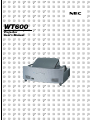
WT600
Projector
User’s Manual
WT600 User’s Manual Supplement
This document provides updated information that supplements the WT600 User’s Manual. Read this supplement as well as the
User's Manual.
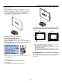
1 Correction to “What’s in the Box?”
Although a Quick Connect Guide is shown on page iii of the user’s manual, the WT600 SETUP GUIDE is actually included with
the projector.
First read the WT600 SETUP GUIDE before operating the projector.
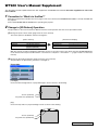
2 Change in [3D Reform] Operation
The procedures in the user's manual are different from the actual operation. See the correct procedures below.
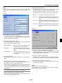
(1) Change in layout of menu items (page 6-3 of the user’s manual)
The menu options in 3D Reform has been changed to:
[User’s manual]
Cornerstone
Keystone
Pincushion
Horizontal, Vertical
Horizontal, Vertical,
Balance (Vertical)
[Actual menu display]
앸
Pincushion
Cornerstone
Keystone
Left/Right, Top, Bottom
Horizontal, Vertical
With this change, the order in displaying adjustment screens is the same order as the above when the 3D REFORM button
on the remote control is pressed: Pincushion → Cornerstone → Keystone → Pincushion → ... (page 1-4 and 1-7 of the user’s
manual)
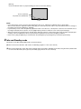
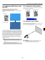
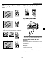
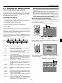
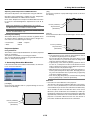
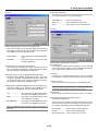
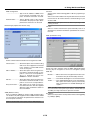
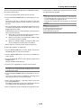
(2) Change in [Pincushion] operation (page 6-13 of the user’s manual)
The procedures for [Pincushion] correction is changed as:
Pincushion
[Left/Right]
Correct the left and right side on a projected image to level as shown in the drawing.
Screen (solid line)
Projected area (dotted line)
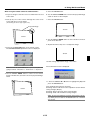
[Top]
Correct the top side on a projected image to level as shown in the drawing.
Screen (solid line)
Projected area (dotted line)
Continued on the next page.
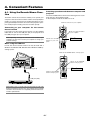
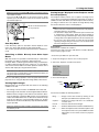
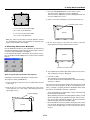
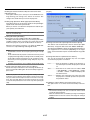
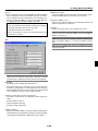
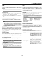
[Bottom]
Correct the bottom side on a projected image to level as shown the drawing.
Screen (solid line)
Projected area (dotted line)
NOTE:
• In the [Pincushion] screen, when the [Top] adjustment value is "0", adjustment of [Bottom] will not be possible* .
Also note that when the adjustment value of the [Top] is a small value (on the order of +5), there will be almost no change of
the image even when the [Bottom] is adjusted*.
• In [Pincushion] screen, when the [Bottom] adjustment value is less than “0”, a small portion can be lost at the bottom area of
the image. To display the lost portion, use the [Digital Zoom] function to reduce the size of the projected image.*
• When [Cornerstone] or [Keystone] has already been adjusted, selection of [Pincushion] will not be possible. To display [Pincushion], return the adjustment values of [Cornerstone] or [Keystone] to the factory shipping conditions.
* Each note for [Top] and [Bottom] is reversed when the [Ceiling Rear] or [Ceiling Front] is selected in [Orientation]
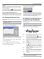
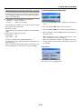
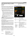
3 Idle and Standby mode
Information on the Idle and Standby mode is revised as follows:
(1) The correct factory default is “Idle” mode, not Standby. (page 6-17 of the user’s manual)
(2) The current explanation states that Factory Default option resets Idle to Standby, but actually using the Factory Default will
not return the Idle mode (factory preset) to Standby. (page 6-25 of the user’s manual)
LIMITED WARRANTY
GARANZIA LIMITATA
Except as specified below, the warranty that may be provided by the
dealer covers all defects in material or workmanship in this product.
The following are not covered by the warranty:
A parte la specificazione seguente, la graanzia che potrebbe essere
fornita dal rivenditore copre tutti i difetti di materiali o nella lavorazione
in questo prodotto. I seguenti non sono coperti dalla garanzia :
1. Any product on which the serial number has been defaced, modified
or removed.
2. Damage, deterioration or malfunction resulting from;
a. Accident, misuse, abuse, neglect, fire, water, dust, smoke, lightning or
other acts of nature, unauthorized product modification, or failure to follow instructions supplied with the product.
b. Repair or attempted repair by non-authorized persons.
c. Any shipment of product (claim must be presented to the carrier).
d. Removal or installation of the product.
e. Any other causes which do not relate to a product defect.
3. Cartons, carrying cases, batteries, external cabinets, CDROM, or
anyaccessories used in connection with the product.
4. Removal or installation charges.
5. Cost of initial technical adjustments (set-up), including adjustment
of user controls. These costs are the responsibility of the dealer from
whom the product was purchased.
6. Payment of shipping charges.
1. Ogni prodotto che ha il numero seriale difettoso, modificato o rimosso.
2. Danni, deterioramento o malfunzionamento risultanti da;
a. Incidenti, abuso, cattivo uso, negligenza, fuoco, acqua, polvere, fumo,
fulmini o altri atti naturali di tipo naturale, modifiche inautorizzate del
prodotto, o errori nel seguire le istruzioni fornite con il prodotto.
b. Riparazioni o tentativi di riparazioni effettuati da persono non autorizzate.
c. Qualsiasi trasporto del prodotto (i reclami devono essere presentati dal
corriere).
d. Rimozione o installazione del prodotto.
e. ogni altra causa non relativa ad un deficit del prodotto.
3. Cartoni, scatole di trasporto, batterie, armadietti esterni, CDROM, o
qualsiasi altro accessorio annesso al prodotto.
4. Carichi di rimozione o installazione.
5. Costi di aggiustamenti tecnici iniziali (set-up), includendo i comandi
di regolazione. Il rivenditore dal quale avete acquistato il prodotto è
responsabile di ciò.
6. Pagamento delle spese di consegna.
GARANTIE LIMITEE
GARANTÍA LIMITADA
Mis à part les point indiqués ci-dessous, la garantie pouvant être
couverte par le revendeur comporte l’ensemble des défauts se
rapportant au matériel ou aux travaux d’assemblage sur ce produit.
Les points suivants ne sont pas couverts par la garantie:
A excepción de lo que se especifica abajo, la garantía que puede ser
suministrada por el distribuidor cubre todos los defectos en material o
elaboración en este producto. Lo siguiente no es cubierto por la garantía:
1. Les produits dont les numéro de série a été effacé, modifié ou retiré.
2. Dommages, dégâts ou dysfonctionnement suite à;
a. Un accident, mauvaise utilisation, abus, négligences, incendies, dégats
dûs aux eaux, à la poussière, à la fumée, aux éclairs ou autres phénomènes
naturels, à une modification non autorisée du produit, ou à la nonconformité aux instructions fournies avec le produit.
b. Réparation ou tentative de réparation par des personnes non autorisées.
c. Toute expédition du produit (les plaintes doivent être adressées à la société
de frêt).
d. Démontage ou installation du produit.
e. Toute autre cause ne se rapportant pas à un défaut du produit.
3. Les cartons, boîtes, piles, caissons externes, CDROM, ou tout autre accessoire utilisé avec ce poduit.
4. Prix de démontage ou d’installation.
5. Coût des réglages techniques de base (mise au point), incluant les
réglages des commandes utilisateurs. Ces coûts sont placés sous
la responsabilité du revendeur auprès duquel le produit a été acheté.
6. Paiement des frais de transport.
1. Cualquier producto en el cual el número serial haya sido desfigurado,
modificado o removido.
2. Daños, deterioro o malfuncionamiento resultado de;
a. Accidente, mal manejo, abuso, negligencia, fuego, agua, polvo, humo,
relámpagos u otros fenómenos naturales, modificaciones del producto
sin autorización, fallas en el seguimiento de las instrucciones
suministradas con el producto.
b. Reparación o intentos de reparación por personas no autorizadas.
c. Cualquier envío del producto (el reclamo debe presentarse al
transportador).
d. Remoción o instalación del producto.
e. Cualquier otra causa que no este relacionada con un defecto del producto.
3. Cartones, estuches de transporte, pilas, gabinetes externos,
CDROM, o cualquier accesorio utilizado en conexión con el producto.
4. Costos por instalación o remoción.
5. Costo de los ajustes técnicos iniciales (configuración), incluyendo
el ajuste de los controles de usuario. Estos costos son
responsabilidad del distribuidor donde se adquirió el producto.
6. Pago de los costos de envío.
BESCHRÄNKTE GARANTIE
BEGRÄNSAD GARANTI
Außer in den unten beschriebenen Fällen deckt die vom Händler unter
Umständen gewährte Garantie alle Material- oder Herstellungsfehler
dieses Produktes ab. In den folgenden Fällen wird keine Garantie
gewährt:
Garantin som ges av återförsäljaren täcker alla brister i material och
utförande med undantag av vad som anges nedan. Följande täcks inte
av garantin:
1. Wenn die Seriennummer des Produktes unleserlich gemacht,
geändert oder entfernt worden ist.
2. Bei einer Beschädigung, Beeinträchtigung oder Funktionsstörung,
die aus folgenden Fällen resultiert:
a. Unfall, falscher Gebrauch, Missbrauch, Fahrlässigkeit, Feuer, Wasser,
Staub, Rauch, Blitzeinschlag oder andere Naturereignisse, nicht
autorisierte Veränderungen des Produktes oder die Missachtung der dem
Produkt beigefügten Anleitung.
b. Reparatur oder der Versuch einer Reparatur durch nicht autorisierte
Personen.
c. Jeglicher Transport des Produktes (die Haftung liegt in diesem Fall bei
der den Transport durchführenden Person).
d. Entfernung oder Installation des Produktes.
e. Jegliche andere Ursachen, die nicht mit einem Defekt dieses Produktes
zusammenhängen.
3. Verwendung von Kartons, Transportkisten, Batterien, Außengehäusen,
CD-ROMs oder anderem Zubehör zusammen mit diesem Produkt.
4. Entfernungs- oder Installationsforderungen und –kosten.
5. Kosten der technischen Anfangseinstellungen (Setup), einschließlich
der Einstellungen der Benutzersteuerungen. Diese Kosten sind vom
Händler zu tragen, von dem das Produkt erworben wurde.
6. Bezahlung von Transportkosten.
1. Produkter vars serienummer har blivit oläsligt, modifierats eller tagits
bort.
2. Skador, försämring eller felfunktion som beror på:
a. Olyckor, fel bruk, missbruk, vanskötsel, brand, vatten, rök, stoft, åska
eller annan orsak som beror på naturen, icke auktoriserad modifikation
av produkten samt underlåtenhet att följa anvisningarna som lämnas med
produkten.
b. Reparationer eller försök på reparation av icke auktoriserade personer.
c. Transportskador (dessa bör riktas till transportföretaget).
d. Avmontering eller installation av produkten.
e. Övriga orsaker som inte har något samband med produktens fel.
3. Förpackningslådor, bärväskor, batterier, externa höljen, CD-ROMskivor samt andra tillbehör som används tillsammans med produkten.
4. Avmonterings- och installationskostnader.
5. Kostnader för tekniska justeringar (inställning), inklusive justering
av användarreglagen. Dessa kostnader är återförsäljarens ansvar
där produkten köpts.
6. Betalning för transportkostnader.
WT600
Projector
User’s Manual
English
Deutsch
Français
Italiano
Español
Svenska
WARNING TO CALIFORNIA RESIDENTS:
Handling the cables supplied with this product, will expose you to lead, a chemical known to the State of California to cause birth defects or other reproductive
harm. Wash hands after handling.
Important Information
RF Interference
Safety Cautions
Precautions
WARNING
The Federal Communications Commission does not allow any modifications or changes to the unit EXCEPT
those specified by NEC Soluctions (America), Inc. in this
manual. Failure to comply with this government regulation could void your right to operate this equipment. This
equipment has been tested and found to comply with
the limits for a Class B digital device, pursuant to Part 15
of the FCC Rules. These limits are designed to provide
reasonable protection against harmful interference in a
residential installation. This equipment generates, uses,
and can radiate radio frequency energy and, if not installed and used in accordance with the instructions, may
cause harmful interference to radio communications.
However, there is no guarantee that interference will not
occur in a particular installation. If this equipment does
cause harmful interference to radio or television reception, which can be determined by turning the equipment
off and on, the user is encouraged to try to correct the
interference by one or more of the following measures:
Please read this manual carefully before using your NEC WT600
Projector and keep the manual handy for future reference. Your
serial number is located on the right side of your projector. Record
it here:
CAUTION
To turn off main power, be sure to remove the plug
from power outlet.
The power outlet socket should be installed as near to
the equipment as possible, and should be easily accessible.
CAUTION
TO PREVENT SHOCK, DO NOT OPEN THE CABINET.
NO USER-SERVICEABLE PARTS INSIDE.
REFER SERVICING TO QUALIFIED NEC SERVICE
PERSONNEL.
This symbol warns the user that uninsulated voltage
within the unit may be sufficient to cause electrical shock.
Therefore, it is dangerous to make any kind of contact
with any part inside of the unit.
• Reorient or relocate the receiving antenna.
• Increase the separation between the equipment and receiver.
• Connect the equipment into an outlet on a circuit different
from that to which the receiver is connected.
This symbol alerts the user that important information
concerning the operation and maintenance of this unit
has been provided.
The information should be read carefully to avoid problems.
• Consult the dealer or an experienced radio / TV technician
for help.
In UK, a BS approved power cable with moulded plug has a
Black (five Amps) fuse installed for use with this equipment. If a
power cable is not supplied with this equipment please contact
your supplier.
WARNING
TO PREVENT FIRE OR SHOCK, DO NOT EXPOSE THIS
UNIT TO RAIN OR MOISTURE.
DO NOT USE THIS UNIT’S GROUNDED PLUG WITH AN
EXTENSION CORD OR IN AN OUTLET UNLESS ALL
THREE PRONGS CAN BE FULLY INSERTED.
DO NOT OPEN THE CABINET. THERE ARE HIGH-VOLTAGE COMPONENTS INSIDE. ALL SERVICING MUST BE
DONE BY QUALIFIED NEC SERVICE PERSONNEL.
Important Safeguards
These safety instructions are to ensure the long life of your projector and to prevent fire and shock. Please read them carefully
and heed all warnings.
Installation
1. For best results, use your projector in a darkened room.
2. Place the projector on a flat, level surface in a dry area away
from dust and moisture.
3. Do not place your projector in direct sunlight, near heaters or
heat radiating appliances.
4. Exposure to direct sunlight, smoke or steam can harm the
mirror and internal components.
5. Handle your projector carefully. Dropping or jarring can damage internal components.
6. Do not place heavy objects on top of the projector.
7. If you wish to have the projector installed on the ceiling:
a. Do not attempt to install the projector yourself.
DOC Compliance Notice
This Class B digital apparatus meets all requirements of the
Canadian Interference-Causing Equipment Regulations.
Acoustic Noise Information Ordinance-3. GSGV:
The sound pressure level is less than 70 dB (A) according
to ISO 3744 or ISO 7779.
RADIACTION LASER NO
RAYONNEMENT LASER NE PAS
MIRE AL RAYO PRODUCTO REGARDER DANS LE FAISCEAU
LASER RADIATIONAPPAREIL A LASER DE CLASSE2
DO NOT STARE INTO BEAM LASER CLASSE2
LASER-STRAHLUNG
WAVE LENGTH:650nm
NICHT IN DEN STRAHL
MAX. OUTPUT :1mW
BLICKEN! LASER KLASSE2
CLASS LASER PRODUCT
CLASS 2 LASER PRODUCT EN60825-1:1994+A11:1996 JIS C 6802:1998 IEC 60825-1:1993+A1:1997
b. The projector must be installed by qualified technicians in
order to ensure proper operation and reduce the risk of
bodily injury.
MADE IN CHINA
c. In addition, the ceiling must be strong enough to support
the projector and the installation must be in accordance
with any local building codes.
This label is on the side of the remote control.
CAUTION
Do not look into the laser pointer while it is on and do
not point the laser beam at a person. Serious injury
could result.
d. Please consult your dealer for more information.
ii
Important Information
6. Do not eject the PC card or LAN card while its data is being accessed. Doing so can damage your PC card or LAN
card.
Fire and Shock Precautions
1. Ensure that there is sufficient ventilation and that vents are
unobstructed to prevent the build-up of heat inside your projector. Allow at least 4 inches (10 cm) of space between your
projector side and a wall.
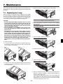
Lamp Replacement
•
To replace the lamp, follow all instructions provided on page
7-1.
•
3. Do not place any liquids on top of your projector.
Be sure to replace the lamp when the message "The lamp
has reached the end of its usable life. Please replace the
lamp." appears. If you continue to use the lamp after the
lamp has reached the end of its usable life, the lamp bulb
may shatter, and pieces of glass may be scattered in the
lamp case. Do not touch them as the pieces of glass may
cause injury.
4. Do not look into the mirror or the light source while the projector is on. Serious damage to your eyes could result.
If this happens, contact your NEC dealer for lamp replacement.
2. Prevent foreign objects such as paper clips and bits of paper
from falling into your projector.
Do not attempt to retrieve any objects that might fall into your
projector. Do not insert any metal objects such as a wire or
screwdriver into your projector. If something should fall into
your projector, disconnect it immediately and have the object
removed by a qualified NEC service personnel.
•
5. Do not block the light path between the light source and the
final mirror with any objects. Doing so could cause the object
to catch on fire.
6. The projector is designed to operate on a power supply of
100-120 or 200-240 V 50/60 Hz AC. Ensure that your power
supply fits this requirement before attempting to use your
projector.
Allow a minimum of 90 seconds to elapse after turning off
the projector. Then turn off the main power switch, disconnect the power cable and allow 60 minutes to cool the projector before replacing the lamp.
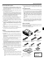
What's in the Box?
Make sure your box contains everything listed. If any pieces are
missing, contact your dealer.
Please save the original box and packing materials if you ever
need to ship your WT600 Projector.
7. Handle the power cable carefully and avoid excessive bending.
A damaged cord can cause electric shock or fire.
8. If the projector is not to be used for an extended period of
time, disconnect the plug from the power outlet.
OF
F
VID
EO
AU
AD
WE
J.
PO
TO
R
RG
ON
B
VIE
CAUTION
WE
R
LA
R
SE
SE
LE
CT
PJ
ASP
EC
T
HE
1. Do not try to touch the ventilation outlet on the both sides as
it can become heated while the projector is turned on.
VO
LUM
E
LP
MAG
NIF
Y
ZO
OM
POI
NTE
R
SLI
FRE
EZE
3D
PIC
-MU
TE
FOL
DER
SLID
E
LIS
RE
FO
RM
DE
FOC
US
T
Remote control
(7N900362)
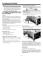
2. Do not attempt to move or carry the projector using the mirror cover.
Doing so can result in the projector overturning and causing
injury. Using the two side handles is the proper way to move
the projector.
Projector
Batteries
When carrying or transporting the projector, close and lock
the mirror cover with the mirror cover lock switch.
3. The carrying handles are designed for the purpose of carrying the projector.
Power cable
(North America: 7N080204)
(Europe: 7N080003)
Do not hang from the projector by the carrying handles in a
ceiling mounted installation. Doing so may result in the carrying handles separating from the unit or the projector may
separate from the mount resulting in personal injury.
4. Enable High-Speed Fan mode if you continue to use the projector for consecutive days. (From the Advanced menu, select [Projector Options] → [Setup] → [Page 4] → [High Speed
Fan Mode].)
RGB signal cable
(7N520012
*
While the message "Please wait a moment." appears. This
message will be displayed after the projector is turned
off.
*
y
C ilit e
NE e Ut Guid
ar n
ftw tio
So tal a
Ins
While the Hour Glass icon appears.
's
er al
Us anu
M
Doing so can cause damage to the projector:
*
Remote Control Cable
(07N520019)
DVI-D signal cable
(7N520007)
USB cable
(7N520013)
p
tu
Se ide
Gu
5. Do not unplug the power cable from the wall outlet under any
one of the following circumstances.
DVI-A to VGA signal
cable
(7N520011)
Stickers (Use as appropriate)
While the cooling fans are running. (The cooling fans continue to work for 90 seconds after the projector is turned
off).
CD-ROM (7N950108)
Projector User Supportware
For North America only
Registration card
Limited warranty
Mirror cleaning cloth (24BS7251)
Dust-proof cover (24BS7271)
iii
For Europe only
Guarantee policy
Table of Contents
Important Information ..................................................... ii
Selecting Noise Reduction Level ........................................................... 6-9
Signal Type ........................................................................................... 6-9
Picture Management .................................................................................. 6-9
User Adjust (when using User 1 to 4) ................................................... 6-9
Selecting Gamma Correction Mode ................................................. 6-9
Selecting Color Correction ............................................................... 6-9
Selecting White Peaking .................................................................. 6-9
Adjusting Color Temperature and White Balance ........................... 6-10
Selecting Base Setting ................................................................... 6-10
Presentation/sRGB/Graphic/Video/Movie
Projector Options .................................................................................... 6-10
Using 3D Reform ................................................................................ 6-10
Digital Zoom ....................................................................................... 6-13
Menu [Page 1] .................................................................................... 6-14
Selecting Menu Language/Selecting Menu Mode/Customizing the Menu/
Selecting a Projector Pointer Icon/Selecting a Mouse Pointer Icon/Selecting Menu Display Time
Menu [Page 2] .................................................................................... 6-14
Turning On / Off Source Display/Turning On / Off Message/Selecting Menu
Color
Setup [Page 1] .................................................................................... 6-15
Setting Lamp Mode to Normal or Eco/Selecting Projector Orientation/
Selecting a Color or Logo for Background/Setting RGB for RGB OUT/
Setting Closed Caption
Setup [Page 2] .................................................................................... 6-15
Setting Viewer Options/Selecting Capture Options/Setting Mouse Button and Sensitivity
Setup [Page 3] .................................................................................... 6-16
Selecting Signal Format
Setup [Page 4] .................................................................................... 6-16
Enabling Auto Adjust/Enabling Auto Start/Enabling Power Management/
Enabling Power Off Confirmation/Enabling Horizontal and Vertical Keystone Correction Save/Enabling High Speed Fan Mode/Enabling Idle
Mode/Clearing Lamp Hour Meter
Setup [Page 5] .................................................................................... 6-17
Selecting Communication Speed/Selecting Default Source/Disabling the
Cabinet Buttons
Selecting Aspect Ratio and Position for Screen .................................. 6-18
Setting LAN Mode ............................................................................... 6-18
IP Address ..................................................................................... 6-18
Network Type (required for wireless only) ..................................... 6-19
WEP (for Wireless only) ................................................................ 6-19
Mail ................................................................................................ 6-20
Status ............................................................................................ 6-21
DHCP ............................................................................................. 6-21
Setting a Password ............................................................................. 6-22
Security .............................................................................................. 6-23
Tools ........................................................................................................ 6-25
Using Sleep Timer .............................................................................. 6-25
Using Capture ..................................................................................... 6-25
Using PC Card Files ............................................................................ 6-25
Using ChalkBoard ............................................................................... 6-25
Help ......................................................................................................... 6-25
Contents ............................................................................................. 6-25
Information ......................................................................................... 6-25
Remaining Lamp Time Display ................................................................ 6-25
Returning to Factory Default .................................................................... 6-25
Safety Cautions .................................................................................................. ii
What's in the Box? ............................................................................................ iii
1. Introduction ........................................................... 1-1
1-1. Introduction to the Projector ................................................................... 1-1
1-2. Part Names of the Projector .................................................................... 1-2
Opening and Closing the Mirror Cover ...................................................... 1-3
Top Features .............................................................................................. 1-4
Terminal Panel Features ............................................................................. 1-5
1-3. Part Names of the Remote Control ......................................................... 1-6
Battery Installation ..................................................................................... 1-8
Remote Control Precautions ...................................................................... 1-8
Operating Range for Wireless Remote Control .......................................... 1-8
Using the Remote Control in Wired Operation ........................................... 1-8
2. Installation and Connections ...................................... 2-1
2-1. Setting Up the Screen and the Projector ................................................. 2-2
Selecting a Location .................................................................................. 2-2
Screen Dimensions ............................................................................... 2-2
Throw Distance ..................................................................................... 2-2
2-2. Making Connections ............................................................................... 2-3
When Viewing a DVI Digital Signal: ........................................................... 2-3
Connecting Your PC or Macintosh Computer ............................................ 2-3
To connect SCART output (RGB) ............................................................... 2-4
Using two RGB inputs simultaneously ....................................................... 2-4
Connecting an External Monitor ................................................................ 2-5
Connecting Your DVD Player ..................................................................... 2-6
Connecting Your VCR or Laser Disc Player ............................................... 2-7
Connecting the Supplied Power Cable ....................................................... 2-7
3. Projecting an Image (Basic Operation) ........................... 3-1
3-1. Turning on the Projector ......................................................................... 3-1
3-2. Selecting a Source .................................................................................. 3-2
3-3. Adjusting the Picture Size and Position ................................................... 3-2
3-4. Optimizing RGB Picture Automatically .................................................... 3-4
3-5. Turning Up or Down Volume ................................................................... 3-4
3-6. Using the Laser Pointer ........................................................................... 3-4
3-7. Turning off the Projector ......................................................................... 3-5
4. Convenient Features ................................................ 4-1
4-1. Using the Remote Mouse Function ......................................................... 4-1
4-2. Turning Off the Image and Sound ........................................................... 4-2
4-3. Freezing a Picture .................................................................................... 4-2
4-4. Using the Pointer .................................................................................... 4-2
4-5. Enlarging and Moving a Picture .............................................................. 4-3
4-6. Getting the On-line Help .......................................................................... 4-3
4-7. Using a USB Mouse ................................................................................ 4-3
4-8. Changing Background Logo .................................................................... 4-4
4-9. Making Freehand Drawings on a Projected Image (ChalkBoard) ............. 4-4
4-10. USB Memory Device or USB Memory Card Reader Support ................. 4-5
5. Using the Viewer ..................................................... 5-1
5-1. Making the Most out of the Viewer Function ........................................... 5-1
5-2. Operating the Viewer Function from the Projector (playback) ................. 5-2
Projecting slides (Viewer) .......................................................................... 5-2
Auto Play Mode ......................................................................................... 5-3
Switching to Slides Directly from Other Input Modes ................................ 5-3
Viewing Digital Images .............................................................................. 5-3
Storing Images Displayed on the Projector on the PC card (Capture) ....... 5-3
Deleting Captured Images ......................................................................... 5-4
Using the PC Card Files Fucntion (PC Card Files) ...................................... 5-4
7. Maintenance .......................................................... 7-1
7-1. Replacing the Lamp ................................................................................ 7-1
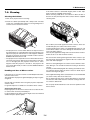
7-2. Cleaning .................................................................................................. 7-2
Cleaning the Cabinet .................................................................................. 7-2
Handling and Care of Mirror surface ......................................................... 7-2
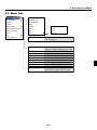
6. Using On-Screen Menu .............................................. 6-1
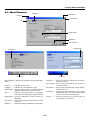
6-1. Basic Menu Operation ............................................................................. 6-1
Using the Menus ....................................................................................... 6-1
Customizing the Menu ............................................................................... 6-1
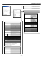
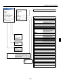
6-2. Menu Tree ............................................................................................... 6-2
6-3. Menu Elements ....................................................................................... 6-5
6-4. Entering Alphanumeric Characters by Using the Menu ........................... 6-6
6-5. Menu Descriptions & Functions .............................................................. 6-6
Source Select ............................................................................................ 6-6
RGB/Video/S-Video/DVI (DIGITAL/ANALOG)/Viewer/LAN/Entry List
Picture ....................................................................................................... 6-7
Volume ...................................................................................................... 6-7
Image Options ........................................................................................... 6-8
Selecting Aspect Ratio .......................................................................... 6-8
Masking Unwanted Area (Blanking) ...................................................... 6-8
Adjusting Position and Clock ................................................................ 6-8
Selecting Resolution ............................................................................. 6-8
Selecting Overscan Percentage ............................................................. 6-8
Selecting Video Filter Level ................................................................... 6-9
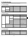
8. Troubleshooting ...................................................... 8-1
8-1. Power Indicator ....................................................................................... 8-1
8-2. Status Indicator ....................................................................................... 8-1
8-3. Lamp Indicator ........................................................................................ 8-1
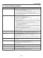
8-4. Common Problems & Solutions ............................................................. 8-2
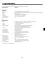
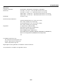
9. Specification ......................................................... 9-1
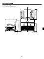
10. Appendix ............................................................ 10-1
10-1. Cabinet Dimensions ............................................................................ 10-1
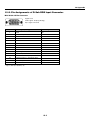
10-2. Pin Assignments of D-Sub RGB Input Connector ............................... 10-2
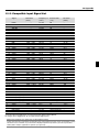
10-3. Compatible Input Signal List ............................................................... 10-3
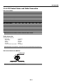
10-4. PC Control Codes and Cable Connection ............................................. 10-4
10-5. Using Software Keyboard .................................................................... 10-5
10-6. Operation Using an HTTP Brouther ..................................................... 10-6
iv
1. Introduction
• Supports most IBM VGA, SVGA, XGA, Macintosh, component signal (YCbCr/YPbPr) or other RGB signals within a horizontal frequency range of 15 to 100 kHz and a vertical frequency range of 50 to 120 Hz. This includes NTSC, NTSC4.43,
PAL, PAL-M, PAL-N, PAL60 and SECAM standard video signals
1-1. Introduction to the Projector
This section introduces you to the WT600 Projector and describes
key features and controls.
Congratulations on Your Purchase of The WT600
Projector
The WT600 is a sophisticated four aspherical mirror XGA projector. With the WT600 you will be able to project images up to 100"
(measured diagonally) from your DVD player, VCR, satellite
hookup, HDTV source, PC, Workstation or Macintosh computer
(desktop or notebook) and images from your digital camera PC
Card or compact flash memory. The WT600 provides for wireless or wired network connectivity when used with an optional
network PC card. With input and output flexibility, long lamp life
and a full function remote, the WT600 lets you immerse yourself
in short throw large screen viewing.)
Features you’ll enjoy on the WT600:
• Super short focal length
• 40" to 100" diagonal image display from 26 inches or less to
the screen
• Wireless or wired networking capable
NOTE: Composite video standards are as follows:
NTSC: U.S. TV standard for video in U.S. and Canada.
NTSC4.43: TV standard used in Middle East countries.
PAL: TV standard used in Western Europe.
PAL-M: TV standard used in Brazil.
PAL-N: TV standard used in Argentine, Paraguay and Uruguay.
PAL60: TV standard used for NTSC playback on PAL TVs.
SECAM: TV standard used in France and Eastern Europe.
*1 Do not attempt to mount the projector on the ceiling yourself. To ensure proper operation and reduce the risk of bodily
injury a qualified technician must install the projector. In addition, the ceiling must be strong enough to support the projector and the installation must be in accordance with any
local building codes. Please consult your dealer for more
information.
*2 HDTV 1080p (1920⳯1080), HDTV 1080p (1920⳯1080) and
HDTV 720 p (1280⳯720) are displayed with NECs Advanced
AccuBlend technology
• Email projector status information to selected individuals
• USB memory storage provides for computerless presentations
Thank you for your purchase of the NEC WT600 projector.
• UXGA compatible, XGA native resolution
• Sealed optics reduce maintenance when ued in smoky or dusty
environments
For additional information, please visit our website at:
US: http://www.necvisualsystems.com
Europe: http://www.nec-europe.com/
Global: http://www.nec-pj.com/
• Core technologies – Advanced AccuBlend™, Advanced
AutoSense™, VORTEX Technology Plus™ for highest quality
of image display and ease of use
• 3D Reform enhanced image technology for increased projector versatility that provides for horizontal, vertical and diagonal keystone corerction
• Display 16:9 or 4:3 information and fill the screen
• HDTV (1080p, 1080i, 720p) and SDTV (576p, 576i, 480p, 480i)
compatibility
• Smart security settings for password protection, control panel
lock, menu lock and PC card protection key to help prevent
unauthorized access and adjustments to the projector
• ADA508 and Executive Order 13221 Federal Government
compliance
• Digital photo viewer to display larger than life images from
your digital cameras PC card or compact flash card
• Easy set up and operation
• Eco-mode™ lamp technology for increased lamp life and energy savings
• Wireless and wired remote control operation
• External control via RS232, USB or Network
• NEC exclusive Advanced AccuBlend intelligent pixel blending technology provides for extremely accurate image compression and HDTV (1920⳯1080) display resolution*2
1-1
1. Introduction
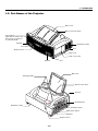
1-2. Part Names of the Projector
Mirror cover
Mirror cover lock switch
Front indicator
Lights blue to indicate that
the projector is turned on
or in the Idle mode.
Speaker
Ventilation (outlet)
Foot
Foot
Remote sensor
Lamp cover
Lamp cover screw
Speaker
Foot
Mirror face
Carrying handle
Bottom of the mirror
S
U
AT
3D R
O
EF
R
EL
C
AN
C
ER
TE
EN
T
C
LE
SE
E
C
R
U
U
SO
T
OU
DIO
AU
Terminal panel
IN B
DIO RG
AU
I-I
DV
T
B OU
RG
B
US
Ventilation (outlet)
S
U
C
B IN
RG
FO
PC
D
AR
C
M
EN
TO ST
AU JU
AD
M
PO
/
N Y
O B
D
AN
ST
W
ER
ST
LA
M
P
Controls
PC
E PC
MOT
RE IN
L
RO
NT
CO
RD
CA
I-I
DV
IN
O IN
DE
S-VI
Ventilation (inlet)
O IN
VIDE
IN
DIO
AU
R
L
O
/MON
Main Power Switch
AC Input
Remote sensor
1-2
1. Introduction
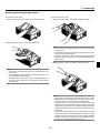
Opening and Closing the Mirror Cover
To close the mirror cover:
1. Slowly close the mirror cover while holding both ends.
To open the mirror cover:
1. Slide the mirror cover lock switch to the unlock position.
1
1
2. Slowly open the mirror cover holding both ends.
NOTE:
• Do not release your hold of the mirror cover until the mirror cover
is fully closed.
• Do not apply excessively strong pressure against the mirror cover
or mirror surface while closing it.
• Keep finger prints off the mirror surface. Leaving finger prints in
the mirror surface might cause an unwanted shadow and poor
picture quality.
2
2. Slide the mirror cover lock switch to the lock position.
NOTE:
• Do not release your hold of the mirror cover until the mirror cover
is fully open.
• Do not apply excessively strong pressure against the mirror cover
or mirror surface while opening it.
• Keep finger prints off the mirror surface. Leaving finger prints in
the mirror surface might cause an unwanted shadow and poor
picture quality.
2
NOTE:
• The projector cannot be turned on when the mirror cover is closed.
• Keep any items out of the light path or the mirror. Failure to do so
may cause objects to catch on fire in unexpected places.
• The projector has a sensor which detects an object in front of the
largest mirror or in the light path. If the sensor detects any object,
the projector will not turn on. If this happens while the projector is
turned on, the image is muted. In either case the STATUS indicator
lights in red.
• The projector has a temperature sensor which detects heat. If the
sensor detects excessive heat in the bottom of the mirror or in the
light path, the projector will not turn on. If this happens while the
projector is turned on, the projector will turn off (the idle mode).
In either case the STATUS indicator flashes in red.
1-3
1. Introduction
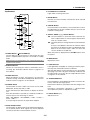
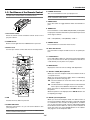
6. PC CARD Access Indicator
Top Features
Lights while accessing a PC card.
6
13
PC CARD
7. ENTER Button
FOCUS
Executes your menu selection and activates items selected
from the menu.
SOURCE
4
MENU
10
8. CANCEL Button
9
8
7
ENTER
5
9. SELECT 왖왔왗왘 (+) (–) / Volume Buttons
CANCEL
왖왔: Use these buttons to select the menu of the item you
wish to adjust. When no menus appear, these buttons
work as a volume control.
3D
REFORM
AUTO
ADJUST
1
POWER
ON/
STAND BY
STATUS
LAMP
1. POWER Button (
Press this button to exit "Menus". Press this button to return
the adjustments to the last condition while you are in the adjustment or setting menu.
SELECT
12
3
2
11
왗왘: Use these buttons to change the level of a selected menu
item.
A press of the 왘 button executes the selection. When
the menus or the Viewer tool bar is not displayed, these
buttons can be used to select a slide, or to move the
cursor in Folder List or Slide List.
When the pointer is displayed, these 왖왔왗왘 buttons move
the pointer.
ON / STAND BY)
Use this button to turn the power on and off when the main
power is supplied and the projector is in the Idle or standby
mode.
10. MENU Button
Displays the menu.
NOTE: To turn on or off the projector, press and hold this button for a
minimum of two seconds.
11. LAMP Indicator
2. STATUS Indicator
If this light blinks red rapidly, it's warning you that the projection lamp has reached the end of its usable life.
Informs you of the projector’s status or what kind of error is
occurring. See the Status Indicator section on page 8-1 for
more details.
After this light appears, replace the lamp as soon as possible.
(See page 7-1). If this is lit green continually, it indicates that
the lamp mode is set to Eco. See the Lamp Indicator section
on page 8-1 for more details.
3. POWER Indicator
When this indicator is green, the projector is on; when this
indicator is orange, it is in idle or standby mode. See the Power
Indicator section on page 8-1 for more details.
12. 3D REFORM Button
Press this button to enter 3D Reform mode to correct the distortion, and make the image square.
4. SOURCE Button
Each time this button is pressed, the item will change as follows:
Use this button to select a video source such as a PC, VCR,
DVD player, Viewer (PC card), or LAN.
Pincushion → Cornerstone → Keystone → ... (the three items
are available only when no adjustment is made)
Press and release this button quickly to display the Source
List.
Each time this button is pressed for a minimum of ONE second, the input source will change as follows:
13. FOCUS Button (+/-)
Adjusts the focus.
RGB → DVI (DIGITAL) → DVI (ANALOG) → Video → S-Video →
Viewer → RGB → ...
If no input signal is present, the input will be skipped.
5. AUTO ADJUST Button
Use this button to adjust Position-H/V and Pixel Clock/Phase
for an optimal picture. Some signals may not be displayed
correctly or take time to switch between sources.
1-4
1. Introduction
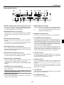
Terminal Panel Features
10
11
14
REMOTE PCCONTROL
IN
AUDIO IN
15
13
PC CARD
VIDEO IN
12 4
USB
2 6
AUDIO IN
AUDIO OUT
DVI-I
RGB
S-VIDEO IN
DVI-I IN
RGB IN
RGB OUT
7
3
1
5
L
/MONO
R
9
8
1. RGB IN / Component Input Connector (Mini D-Sub 15 Pin)
9. VIDEO AUDIO IN Jacks (RCA)
Connect your computer using the supplied RGB cable. This
connector also supports a component signal and SCART output signal. See page 2-4 for more details.
L/MONO: This is your monaural or left channel audio input
for stereo sound coming from the VIDEO source.
R:
This is your right channel audio input for stereo
sound from the VIDEO source.
2. RGB AUDIO IN Mini Jack (Stereo Mini)
This is where you connect audio output from your computer
or DVD player. A commercially available audio cable is required.
10. REMOTE IN Jack (Mini Jack)
Connect your remote control cable here for wired operation.
11. PC CONTROL Port (Mini DIN 8 Pin)
3. DVI-I IN Connector (DVI-I 24 Pin)
Use this port to connect your PC to control your projector via
a serial cable. This enables you to use your PC and serial
communication protocol to control the projector. The NEC optional serial cable (CA03D) is required to use this port. You
can also control the projector by using Dynamic Image Utility
2.0 included on the supplied CD-ROM.
Connect a computer with a DVI output using the supplied DVID cable.
This connector can be used to accept digital and analog signal output from a computer with a DVI connector.
4. DVI-I AUDIO Input Mini Jack (Stereo Mini)
To do so you must first have Dynamic Image Utility 2.0 installed on your PC. If you are writing your own program, typical PC control codes are on page 10-4. A cap is put on the
port at the factory. Remove the cap when using the port.
This is where you connect the audio output from your computer when connected to the DVI input. A commercially available audio cable is required.
12. USB Port (Type B)
5. RGB OUT Connector (Mini D-Sub 15 Pin)
Connect this port to the USB port (type A) of your PC using
the supplied USB cable. You can operate your computer's
mouse functions from the remote control.
You can use this connector to loop your computer image to
an external monitor from the RGB input source.
6. AUDIO OUT Mini Jack (Stereo Mini)
13. USB Port (Type A)
Connect an additional audio equipment here to listen to audio
coming from your computer, Video or S- Video input.
Connect a commercially available mouse that supports USB.
You can operate the menu or Viewer with the USB mouse via
this port.
Note that there is no audio output from this jack during Standby
and Idle.
Note that this port should not be connected to a computer
and that there may be some brands of USB mouse that the
projector does not support.
7. S-VIDEO IN Connector (Mini DIN 4 Pin)
Here is where you connect the S-Video input from an external
source like a VCR.
14 . PC CARD Slot
NOTE: S-Video provides more vivid color and higher resolution than
the traditional composite video format.
Insert a PC card, commercially available LAN card or NEC
optional wireless LAN card here.
8. VIDEO IN Connector (RCA)
15. PC CARD Eject Button
Connect a VCR, DVD player, laser disc player, or document
camera here to project video.
Press to eject a PC card partially.
1-5
1. Introduction
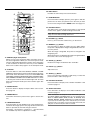
6. POWER OFF Button
1-3. Part Names of the Remote Control
You can use this button to turn your projector off.
NOTE: If you are using a Macintosh computer, you can click either
the right-click or left-click button to activate the mouse.
NOTE: To turn off the projector, press and hold the POWER OFF button for a minimum of two seconds.
CT
LE
SE
7. VIDEO Button
LAS
ER
VIE
WE
R
Press this button to toggle between Video and S-Video inputs.
AUTO
RG
B
ADJ.
ON
PO
WE
R
VID
EO
OF
F
3
8. RGB Button
2
1
Press this button to select RGB, DVI (DIGITAL) or DVI (ANALOG) inputs. Each time this button is pressed, the input source
will change as follows:
1. Infrared Transmitter
Direct the remote control toward the remote sensor on the
projector cabinet.
RGB → DVI (DIGITAL) → DVI (ANALOG) → RGB → ...
2. LASER Pointer
9. VIEWER Button
Beams a laser light when the LASER button is pressed.
Press this button to select the Viewer source.
3. Remote Jack
10. AUTO ADJ. Button
Connect your remote control cable here for wired operation.
Use this button to adjust an RGB source for an optimal picture.
4
6
MENU
5
8
9
11
SELECT
13
ON
OFF
POWER
RGB
VIDEO
7
10
VIEWER
LASER
AUTO ADJ.
11. LASER Button
Press and hold this button to activate the laser pointer. When
lit, you can use the laser to draw your audience's attention to
a red dot that you can place on any object.
12. MENU Button
12
14
Displays the menu for various settings and adjustments.
EN
TE
CAN
R
CE
L
21
23
24
25
26
ASPECT
FREEZE 3D REFORM
HELP
POINTER PIC-MUTE
VOLUME MAGNIFY
When you are in the Computer mode, these buttons work as
a computer mouse.
16
PJ
17
20
13. SELECT 왖왔왗왘 (Mouse) Button
15
SLIDE
When you are in the Projector mode, which is indicated by
lighting the PJ button. See page 4-1.
18
19
22
왖왔 : Use these buttons to select the menu of the item you
wish to adjust.
왗왘 : Use these buttons to change the level of a selected menu
item. A press of the 왘 button executes the selection.
27
ZOOM
FOCUS
When the pointer is displayed, these 왖왔왗왘 buttons move
the pointer.
FOLDER
SLIDE
LIST
28
29
When the pointer is not displayed, these 왖왔왗왘 buttons are
for adjusting the image.
14. ENTER (Left Click) Button
4. LED
When you are in the Computer mode, this button works as
the mouse left button. When this button is pressed and held
for a minimum of two seconds, the drag mode is set. When
you are in the Projector mode, which is indicated by lighting
the PJ button: Use this button to enter your menu selection. It
works the same way as the ENTER button on the cabinet.
See page 4-1 for the Computer mode.
Flashes when any button is pressed.
5. POWER ON Button
When the main power is on, you can use this button to turn
your projector on.
NOTE: To turn on the projector, press and hold the POWER ON button for a minimum of two seconds.
1-6
1. Introduction
4
6
20. HELP Button
21. POINTER Button
MENU
SELECT
13
22. PIC-MUTE Button
POWER
RGB
VIDEO
7
10
Provides the online help or the set information.
5
8
9
11
ON
OFF
VIEWER
LASER
AUTO ADJ.
Press this button to display pointers; press again to hide the
pointer. You can move your pointer icon to the area you want
on the screen using the Select 왖왔왗왘 button. See page 4-2.
12
14
EN
TE
CAN
R
L
CE
PJ
21
17
20
23
24
25
ASPECT
FREEZE 3D REFORM
HELP
POINTER PIC-MUTE
VOLUME MAGNIFY
SLIDE
15
This button turns off the image and sound for a short period
of time. Press again to restore the image and sound.
16
NOTE: When the menu is displayed, a press of this button mutes an
image and sound without turning off the menu.
18
19
22
23. VOLUME (+)(–) Button
Press (+) to increase the volume and (–) to decrease it.
24. MAGNIFY (+)(–) Button
27
ZOOM
FOCUS
Use this button to adjust the image size up to 400%. When
the pointer is displayed, the image is magnified about the center of the pointer.
FOLDER
SLIDE
26
LIST
28
29
When the image is magnified, the pointer is changed to the
magnifying icon.
When the pointer is not displayed, the image is magnified about
the center of the screen. See page 4-3.
15. CANCEL (Right Click) Button
When you are in the Computer mode, this button works as
the mouse right button. When you are in the Projector mode,
which is indicated by lighting the PJ button: Press this button
to exit the Menus. It works the same way as the CANCEL
button on the cabinet. See page 4-1 for the Computer mode.
25. ZOOM (+)(–) Button
Reduces the image size between 80% and 100%.
26. FOCUS (+)(–) Button
Adjust the focus.
16. PJ Button
Press this button to switch the SELECT, CANCEL, and ENTER buttons between the Projector mode (lit red) and the Computer mode. Press this button or any one of the POWER ON/
OFF, MENU, ASPECT, 3D REFORM, HELP, POINTER, MAGNIFY, VIEWER, FOLDER LIST or SLIDE LIST buttons to switch
to the Projector mode and the PJ button lights red. To switch
back to the Computer mode, press the PJ button again. See
page 4-1.
27. SLIDE (+)(–) Button
Press (+) to select the next folder or slide and (–) to select the
previous folder or slide. See page 5-2.
28. FOLDER LIST Button
Press this button to display a list of folders included in a PC
card. See page 5-2.
17. ASPECT Button
29. SLIDE LIST Button
Press this button to display the Aspect Ratio select screen.
See page 6-8.
Press this button to display a list of slides included in a PC
card. See page 5-2.
NOTE: The default is the Computer mode, which allows you to use
the SELECT, CANCEL, and ENTER buttons as your computer mouse.
When the POWER ON/OFF, MENU, ASPECT, 3D REFORM, HELP,
POINTER, MAGNIFY, VIEWER, FOLDER LIST, or SLIDE LIST button
is pressed, the PJ button lights red to indicate that you are in the
Projector mode. If no buttons are pressed within 60 seconds, the
light goes out and the Projector mode is canceled.
18. FREEZE Button
This button will freeze a picture. Press again to resume motion.
19. 3D REFORM Button
Press this button to enter 3D Reform to correct the distortion,
and make the image square. See page 6-10. Each time this
button is pressed, the item will change as follows:
Pincushion → Cornerstone → Keystone → ... (the three items
are available only when no adjustment is made)
1-7
1. Introduction
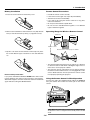
Battery Installation
Remote Control Precautions
1. Press the catch and remove the battery cover.
• Handle the remote control carefully.
• If the remote control gets wet, wipe it dry immediately.
• Avoid excessive heat and humidity.
• If you will not be using the remote control for a long time,
remove the batteries.
• Do not place the batteries upside down.
• Do not use new and old batteries together, or use different
types of batteries together
Operating Range for Wireless Remote Control
2. Remove both old batteries and install new ones (AA). Ensure
that you have the batteries' polarity (+/-) aligned correctly.
7m/22 feet
7m/22 feet
30°
30°
Remote control
Remote sensor on the projector cabinet
3. Slip the cover back over the batteries until it snaps into place.
Do not mix different types of batteries or new and old batteries.
30°
30°
• The infrared signal operates by line-of-sight up to a distance
of about 22 feet/7 m and within a 60-degree angle of the remote sensor on the projector cabinet.
• The projector will not respond if there are objects between
the remote control and the sensor, or if strong light falls on the
sensor. Weak batteries will also prevent the remote control
from properly operating the projector.
Note on Battery Installation:
If you press and hold the SELECT 왖왔왗왘 button while installing new batteries, the remote control may fail to work properly.
Should this happen, remove the batteries and then install them
again without touching the SELECT button.
Using the Remote Control in Wired Operation
Connect one end of the supplied remote cable to the REMOTE
mini jack and the other end to the remote jack on the remote
control.
REMOTE
IN
VIDEO IN
PC CARD
S-VIDEO IN
USB
DVI-I IN
AUDIO IN
AUDIO OUT
DVI-I
RGB
RGB IN
RGB OUT
J
P
M
O
FY
ZO
NI
AG
AS
PE
CT
FR
LP
HE
EE
VO
ZE
PO
3D
IN
TE
M
R
FO
RE
RM
TE
MU
CPI
E
ID
SL
L
/MONO
ME
LU
R
S
CU
FO
FO
LD
ER
SL
ID
E
AUDIO IN
ST
LI
REMOTE PCCONTROL
IN
SE
LE
CT
LAS
ER
VIE
AUT
O ADJ
.
RG
VID
PO
EO
OF
WE
R
B
WE
R
ON
F
NOTE: When the remote cable is inserted into the REMOTE IN jack,
the projector's status is changed from the Standby mode to the Idle
mode.
1-8
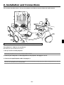
2. Installation and Connections
This section describes how to set up your projector and how to connect video and audio sources.
When installing the projector for the first time, read the WT600 Setup Guide carefully.
Your projector is simple to set up and use.
But before you get started you must first:
1. Set up a screen and the projector.
NOTE: Using a warped screen can cause an image to appear distorted.
2. Connect your computer or video equipment to the projector. See page 2-3 to 2-7.
3. Connect the supplied power cable. See page 2-7.
NOTE: Ensure that the power cable and any other cables are disconnected before moving the projector. When moving the projector or when it is
not in use, close the mirror cover on the top cabinet.
2-1
2. Installation and Connections
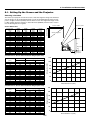
2-1. Setting Up the Screen and the Projector
Selecting a Location
The further your projector is from the screen or wall, the larger the image. The minimum
size the image can be is approximately 40" (1.0 m) measured diagonally when the projector is roughly 2.5 inches (64mm) from the wall or screen. The largest the image can be
is 100" (2.54m) when the projector is about 26 inches (660mm) from the wall or screen.
Use the drawing below as a guide.
Screen width
Screen center
Screen Dimensions
Width
(inch)
32.0
36.0
40.0
44.0
48.0
52.0
53.6
56.0
57.6
60.0
62.4
64.0
67.2
68.0
72.0
76.0
76.8
80.0
Height
(inch)
24.0
27.0
30.0
33.0
36.0
39.0
40.2
42.0
43.2
45.0
46.8
48.0
50.4
51.0
54.0
57.0
57.6
60.0
Width
(mm)
813
914
1016
1118
1219
1321
1361
1422
1463
1524
1585
1626
1707
1727
1829
1930
1951
2032
Height
(mm)
610
686
762
838
914
991
1021
1067
1097
1143
1189
1219
1280
1295
1372
1448
1463
1524
Screen height
Screen size
(inch)
40
45
50
55
60
65
67
70
72
75
78
80
84
85
90
95
96
100
Screen diagonal
B
D
Projector
foot
Back of
projector
C
Throw Distance, Screen Size and Screen Height (Unit: mm)
40
45
50
55
60
65
67
70
72
75
78
80
84
85
90
95
96
100
C
64
114
164
214
263
313
332
362
381
412
441
461
500
510
559
609
619
659
120
Height (mm)
Throw distance (mm)
B
659
729
799
869
939
1010
1037
1080
1107
1149
1191
1219
1275
1289
1359
1428
1443
1499
D
354
386
418
450
482
514
526
546
558
577
596
609
635
641
673
704
711
737
100
Screen size (inch)
Screen size
(inch)
80
60
40
20
0
0
100
200
300
400
500
600
700
Throw distance C (mm)
Throw Distance, Screen Size and Screen Height (Unit: inch)
40
45
50
55
60
65
67
70
72
75
78
80
84
85
90
95
96
100
C
2.5
4.5
6.4
8.4
10.4
12.3
13.1
14.3
15.0
16.2
17.4
18.1
19.7
20.1
22.0
24.0
24.4
25.9
120
Height (inch)
Throw distance (inch)
B
25.9
28.7
31.5
34.2
37.0
39.7
40.8
42.5
43.6
45.2
46.9
48.0
50.2
50.7
53.5
56.2
56.8
59.0
D
100
13.9
15.2
16.5
17.7
19.0
20.2
20.7
21.5
22.0
22.7
23.5
24.0
25.0
25.2
26.5
27.7
28.0
29.0
Screen size (inch)
Screen size
(inch)
80
60
40
20
0
0
5
10
15
20
Throw distance C (inch)
2-2
25
30
2. Installation and Connections
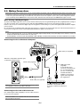
2-2. Making Connections
NOTE: When using with a notebook PC, be sure to connect between the projector and the notebook PC before turning on the power to the
notebook PC. In most cases signal cannot be output from RGB output unless the notebook PC is turned on after connecting with the projector.
* If the screen goes blank while using your notebook PC, it may be the result of the computer's screen-saver or power management software.
* If you accidentally hit the POWER button on the remote control, wait 90 seconds and then press the POWER button again to resume.
When Viewing a DVI Digital Signal:
To project a DVI digital signal, be sure to connect the PC and the projector using the DVI-D signal cable (supplied) before turning on
your PC or projector. Turn on the projector first and select DVI (DIGITAL) from the source menu before turning on your PC.
Failure to do so may not activate the digital output of the graphics card resulting in no picture being displayed. Should this happen,
restart your PC.
Do not disconnect the DVI-D signal cable while the projector is running. If the signal cable has been disconnected and then reconnected, an image may not be correctly displayed. Should this happen, restart your PC.
NOTE:
• Use the supplied DVI-D cable or the one compliant with DDWG (Digital Display Working Group) DVI (Digital Visual Interface) revision 1.0
standard. The DVI-D cable should be within 5 m (196") long.
• The DVI (DIGITAL) connector accepts VGA (640x480), SVGA (800x600), 1152x864, XGA (1024x768) and SXGA (1280x1024 @ up to 60Hz).
Connecting Your PC or Macintosh Computer
AUDIO IN DVI-I
RGB IN
DVI-I IN
REMOTE PCCONTROL
IN
AUDIO IN
R
VIDEO IN
AUDIO IN RGB
USB
PC CARD
S-VIDEO IN
DVI-I IN
AUDIO IN
AUDIO OUT
DVI-I
RGB
RGB IN
RGB OUT
Audio cable (not supplied)
L
/MONO
IBM PC or Compatibles (Desktop type)
or Macintosh (Desktop type)
DVI-D cable (supplied)
RGB signal cable
(supplied)
To mini D-Sub 15-pin
connector on the projector.
It is recommended that
you use a commercially
available distribution
amplifier if connecting a
signal cable longer than
the supplied one.
PHONE
PHONE
Audio cable (not supplied)
IBM VGA or Compatibles (Notebook type) or Macintosh (Notebook
type)
NOTE: For older Macintosh, use a commercially available pin adapter
(not supplied) to connect to your Mac's video port.
Connecting Your PC with a DVI Connector
Use a DVI-D signal cable (supplied) to connect a DVI connector
of your PC to the projector.
NOTE: The WT600 is not compatible with video decoded outputs of
NEC ISS-6020 and ISS-6010.
2-3
2. Installation and Connections
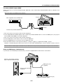
To connect SCART output (RGB)
Before connections: An exclusive SCART adapter (ADP-SC1) and a commercially available SCART cable are required for this
connection.
NOTE: Audio signal is not available for this connection.
Projector
Video equipment such as DVD player
RGB IN
REMOTE PCCONTROL
IN
AUDIO IN
R
VIDEO IN
USB
PC CARD
S-VIDEO IN
DVI-I IN
AUDIO IN
AUDIO OUT
DVI-I
RGB
RGB IN
RGB OUT
L
/MONO
To RGB IN
Female
Commercially available SCART cable
ADP-SC1
1. Turn off the power to the projector and your video equipment.
2. Use the NEC ADP-SC1 SCART adapter and a commercially available SCART cable to connect the RGB input of your projector
and a SCART output (RGB) of your video equipment.
3. Turn on the power to the projector and your video equipment.
4. Use the RGB button on the remote control to select the RGB input.
5. Press the MENU button on the remote control to display the menu.
6. From the Advanced menu, select [Projector Options] → [Setup] → [Page 3] → [Signal Select RGB] → [Scart].
SCART is a standard European audio-visual connector for TVs, VCRs and DVD players. It is also referred to as Euro-connector.
NOTE: The ADP-SC1 SCART adapter is obtainable from your NEC dealer in Europe. Contact your NEC dealer in Europe for more information.
Using two RGB inputs simultaneously
If you need to use two RGB inputs simultaneously, connect the supplied DVI-A to VGA cable as shown below.
DVI-I IN
REMOTE PCCONTROL
IN
AUDIO IN
IBM PC or Compatibles (Desktop
type) or Macintosh (Desktop type)
R
VIDEO IN
RGB IN
PC CARD
S-VIDEO IN
USB
DVI-I IN
RGB IN
AUDIO IN
AUDIO OUT
DVI-I
RGB
RGB OUT
L
/MONO
RGB signal cable
(supplied)
DVI-A to VGA cable
(supplied)
IBM PC or Compatibles (Notebook type)
or Macintosh (Notebook type)
2-4
2. Installation and Connections
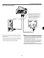
Connecting an External Monitor
RGB OUT
REMOTE PCCONTROL
IN
AUDIO IN
R
VIDEO IN
PC CARD
S-VIDEO IN
USB
DVI-I IN
AUDIO IN
AUDIO OUT
DVI-I
RGB
RGB IN
RGB OUT
L
/MONO
RGB signal cable (commercially available
or supplied with an external monitor)
To mini D-Sub 15-pin connector on the
projector. It is recommended that you use
a commercially available distribution
amplifier if connecting a signal cable
longer than the supplied one.
RGB signal cable
(supplied)
You can connect a separate, external monitor to your projector
to simultaneously view on a monitor the RGB analog image you're
projecting. To do so:
NOTE:
• The RGB OUT connector can output RGB signal even during idle
mode (See page 6-17 for enabling the Idle mode). When the projector goes into idle mode, the image on an external monitor disappears for a moment. Note that the RGB OUT connector will not
output RGB signal during Standby mode.
• When the projector is in the Idle mode, the image may not be
correctly displayed while the cooling fans are running immediately after turning on or off the power. Note that the RGB OUT
connector will not output RGB signal during Standby mode.
• Daisy chain connection is not possible.
1. Turn off the power to your projector, monitor and computer.
2. Use a 15-pin cable to connect your monitor to the RGB OUT
(Mini D-Sub 15 pin) connector on your projector.
3. Turn on the projector, monitor and the computer.
2-5
2. Installation and Connections
Connecting Your DVD Player
AUDIO IN RGB
RGB IN
REMOTE PCCONTROL
IN
AUDIO IN
R
VIDEO IN
USB
PC CARD
S-VIDEO IN
DVI-I IN
AUDIO IN
AUDIO OUT
DVI-I
RGB
RGB IN
RGB OUT
L
/MONO
Optional 15-pin-to-RCA
(female)⳯3 cable (ADP-CV1)
Component video RCA⳯3 cable
(not supplied)
Audio Equipment
DVD player
AUDIO IN
L
R
Y
Cb
Cr
Component
Audio cable (not supplied)
You can connect your projector to a DVD player with component
output or Video output. To do so, simply:
1. Turn off the power to your projector and DVD player.
2. If your DVD player has the component video (Y,Cb,Cr) output,
use a commercially available component video cable (RCAX3)
and the optional 15-pin-to-RCA (female)⳯3 cable to connect
your DVD player to the RGB IN connector on the projector.
For a DVD player without component video (Y,Cb,Cr) output,
use common RCA cables (not provided) to connect a composite VIDEO output of the DVD player to the Video Input of
the projector.
3. Turn on the projector and DVD player.
NOTE: Refer to your DVD player's owner's manual for more information about your DVD player's video output requirements.
2-6
L
R
AUDIO OUT
2. Installation and Connections
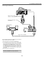
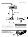
Connecting Your VCR or Laser Disc Player
S-VIDEO IN
VIDEO IN
AUDIO IN
REMOTE PCCONTROL
IN
AUDIO IN
R
VIDEO IN
PC CARD
S-VIDEO IN
USB
DVI-I IN
AUDIO IN
AUDIO OUT
DVI-I
RGB
RGB IN
RGB OUT
L
/MONO
Video cable (not supplied)
Audio cable (not supplied)
S-video cable (not supplied)
Audio equipment
VCR/ Laser disc player
L
R
VIDEO S-VIDEO
AUDIO OUT
AUDIO IN
VIDEO OUT
L
R
Audio cable (not supplied)
3. Turn on the projector and the VCR or laser disc player.
Use common RCA cables (not provided) to connect your VCR,
laser disc player or document camera to your projector.
To make these connections, simply:
NOTE: Refer to your VCR or laser disc player owner's manual for
more information about your equipment's video output requirements.
1. Turn off the power to the projector and VCR, laser disc player
or document camera.
NOTE: An image may not be displayed correctly when a Video or SVideo source is played back in fast-forward or fast-rewind via a scan
converter.
2. Connect one end of your RCA cable to the video output connector on the back of your VCR or laser disc player, connect
the other end to the Video input on your projector. Use an
audio cable (not supplied) to connect the audio from your VCR
or laser disc player to your audio equipment (if your VCR or
laser disc player has this capability). Be careful to keep your
right and left channel connections correct for stereo sound.
CO
NT
RO
L
SE
LE
C
T
CA
RD
IN
R
M
PO
W
STA ER
TU
S
STA
O
N N/
D
BY
DV
I-I
US
B
RG
B IN
DVAUDI
I-I O IN
RG AU
B
DIO
OU
T
RG
B OU
T
2-7
LA
M
P
EN
TE
R
S-VI
DE
O IN
R 3D
EFO
C
AN
C
EL
PC
VIDE
O IN
AD AU
JU TO
ST
/M L
ON
O
SO
U
R
C
E
PC
AU
DIO
IN
R
M
EN
U
RE
MO
IN TE
Connect the supplied power cable to the projector.
First connect the supplied power cable's three-pin plug to the
AC IN of the projector, and then connect the other plug of the
supplied power cable in the wall outlet.
FO
C
U
S
PC
C
AR
D
Connecting the Supplied Power Cable
3. Projecting an Image (Basic Operation)
3. The Basic menu will be displayed in the language you have
selected.
This section describes how to turn on the projector and to project
a picture onto the screen.
3-1. Turning on the Projector
NOTE:
• When plugging in or unplugging the supplied power cable, make
sure that the main power switch is pushed to the off[O] position.
Failure to do so may cause damage to the projector.
• The projector has two power switches: main power switch and
POWER button (POWER ON and OFF on the remote control)
• The projector has a feature to prevent itself from being used by
unauthorized individuals. To use this feature, register your PC card
as a protect key. See "Security" in "Projector Options" on page 6-23
for more details.
To close the menu, press the CANCEL button.
To turn on the main power to the projector, press
the Main Power switch to the ON position ( I ).
OFF
ON
POWER
VIDEO
RGB
VIEWER
LASER
AUTO ADJ.
MENU
SELECT
SELECT
EN
ENTEER
POWER
ON/
STAND BY
STATUS
LAMP
E
When the Lamp mode is set to Eco, the Lamp indicator will light
green.
If one of the following things happens, the projector will not turn
on.
* If the internal temperature of the projector is too high, the
projector detects abnormal high temperature. In this condition the projector will not turn on to protect the internal system. If this happens, wait for the projector's internal components to cool down.
ON
VIEWER
LASER
MENU
* When the lamp reaches its end of usable life, the projector
will not turn on. If this happens, replace the lamp.
L
SELECT
EN
NC
NOTE: To turn the projector on by plugging in the power cable, first
turn on the Main Power switch to ON and use the menu and enable
the "Auto Start" feature. (See page 6-16.) Immediately after turning
on the projector, screen flicker may occur. This is not a fault. Wait 3
to 5 minutes until the lamp lighting is stabilized.
POWER
RGB
CA
After this has been done, you can proceed to the advanced menu
operation.
If you want, you can select the menu language later. See "Language" on page 6-14.
AUTO
ADJUST
1. Use the SELECT 왖 or 왔 button to select one of the seven
languages for the menu.
VIDEO
R
CANCEL
3D
REFORM
When you first turn on the projector, you will get the Startup
screen. This screen gives you the opportunity to select one of
the seven menu languages: English, German, French, Italian,
Spanish, Swedish and Japanese.
To select a menu language, follow these steps:
AUTO ADJ.
TE
PJ
Note on Startup screen (Menu Language Select
screen)
OFF
L
Before you turn on your projector, ensure that
the computer or video source is turned on and
that the mirror cover is open.
Only after you press the ON/STAND BY button
on the projector cabinet or POWER ON button
on the remote control for a minimum of two seconds will the power indicator turn to green and
the projector become ready to use.
TE
R
CA
NC
E
* If the lamp fails to light, and if the STATUS indicator flashes
on and off in a cycle of six times, wait a full minute and then
turn on the power.
PJ
* When the mirror cover is closed.
* If the temperature sensor detects excessive heat in the bottom of the mirror or in the light path, the projector will not turn
on. Remove objects such as dust from the bottom of the mirror.
2. Press the ENTER button to execute the selection.
OFF
ON
POWER
VIDEO
RGB
* The projector has a sensor which detects an object in front of
the largest mirror or in the light path. If the sensor detects any
object, the projector will not turn on. Remove the object.
VIEWER
LASER
AUTO ADJ.
MENU
* Do not illuminate the projector with strong light source such
as halogen lamp.
EN
L
SELECT
TE
R
CA
NC
E
Doing so can cause the object detection sensor to malfunction, resulting in the projector not turning on.
PJ
3-1
3. Projecting an Image (Basic Operation)
3-3. Adjusting the Picture Size and
Position
3-2. Selecting a Source
Selecting the computer or video source
Using the Remote Control
1. Place the projector on a flat level surface and ensure that
the projector is square to the screen.
2. Make the image square
Move the projector left or right to center the image horizontally on the screen.
ON
OFF
POWER
RGB
VIDEO
VIEWER
LASER
AUTO ADJ.
MENU
Press any one of the RGB, VIDEO
or VIEWER buttons.
EN
L
SELECT
TE
R
CA
NC
E
PJ
NOTE: If no input signal is available, the projector will display a blue
background (factory preset).
Selecting from Source List
Source List
PC CARD
FOCUS
SOURCE
MENU
3. Adjust the projected image size
Use the throw chart on page 2-2 to adjust the image size.
Press and quickly release the SOURCE button on the projector
cabinet to display the Source list. Each time the SOURCE button is pressed, the input source will change as follows: "RGB"
(computer or DVD with component output),"DVI (DIGITAL)", "DVI
(ANALOG)", "Video" (VCR, document camera, or laser disc
player), S-Video", "Viewer" (slides on a PC card), or "LAN" (wired
or wireless signal aired from a PC).
To display the selected source, press the ENTER button.
Detecting the Signal Automatically
PC CARD
FOCUS
SOURCE
MENU
Press and hold the SOURCE button for a minimum of 1 second,
the projector will search for the next available input source. Each
time you press and hold the SOURCE button, the input source
will change as follows:
4. Finely adjust the height to keep the projector level
To finely adjust the height, use the feet on the front or rear.
RGB → DVI (DIGITAL) → DVI (ANALOG) → Video → S-Video → Viewer
→ ...
If no input signal is present, the input will be skipped. When the
input source you wish to project is displayed, release the button.
Press the ENTER button.
up
down
Each of the feet height can be changed up to 1.2" (30 mm).
3-2
3. Projecting an Image (Basic Operation)
5. Adjust the focus
Use the FOCUS <+/–> button on the remote control or the
projector cabinet to reduce keystone distortion.
When the top edge of an image is shorter than the bottom
one, press the FOCUS + button to correct the distortion.
Focus adjustment will slightly change the picture position.
If required, reposition the projector.
NOTE:
• The “Horizontal/Vertical Position” option can be adjusted within a
range of 100%.
100%
100%
80%
100%
6. Repeat the above steps if required.
7. Reduce the image (Digital Zoom)
You can reduce and move the projected image
Press the ZOOM button on the remote control to display the
Digital Zoom menu.
Use the 왖 or 왔 to select the Reduction Ratio, Horizontal Position or Vertical Position.
Adjustable zoom area
ASPECT FREEZE 3D REFORM
HELP
ZOOM
POINTER PIC-MUTE
FOCUS
100%
Movable area of displayed
image
• When any adjustment is made to the “Cornerstone” or “Keystone”
option, the “Digital Zoom” option is not available.
* The Digital Zoom option may blur an image because the image is
electronically compressed.
* The Digital Zoom option can reduce the image down to 80% of
its original size while keeping aspect ratio the same as the original.
PJ
VOLUME MAGNIFY
80%
SLIDE
FOLDER
SLIDE
LIST
8. Correct distortion.
Use the 3D Reform button on the remote control or the projector cabinet to correct the distortion. See page 6-10 for more
information.
Zoom
You can reduce the image size between 80% and 100% using the ZOOM button (+/–).
Horizontal Position
Use the 왗 or 왘 to move the picture right or left.
Vertical Position
Use the 왗 or 왘 to adjust the picture up or down.
3-3
3. Projecting an Image (Basic Operation)
3-4. Optimizing RGB Picture Automatically
3-5. Turning Up or Down Volume
Sound level from the speaker and the AUDIO OUT jack (RCA)
on the projector can be adjusted.
increase volume
decrease volume
Adjusting the Image Using Auto Adjust
Optimizing RGB image automatically
Press the Auto Adjust button to optimize an RGB image automatically.
ASPECT FREEZE 3D REFORM
HELP
POINTER PIC-MUTE
VOLUME MAGNIFY
[Poor picture]
ZOOM
FOCUS
SLIDE
FOLDER
SLIDE
OFF
LIST
ON
ASPECT FREEZE 3D REFORM
HELP
POINTER PIC-MUTE
VOLUME MAGNIFY
ZOOM
FOCUS
SLIDE
FOLDER
SLIDE
LIST
POWER
VIDEO
RGB
VIEWER
LASER
AUTO ADJ.
Volume bar
MENU
L
SELECT
EN
TE
R
CA
NC
E
3-6. Using the Laser Pointer
[Normal picture]
You can use the laser to draw your audience's attention to a red
dot that you can place on any object.
Press and hold the LASER button to activate the laser pointer.
OF
Press the Auto Adjust button to fine-tune the computer image or
to remove any vertical banding that might appear and to reduce
video noise, dot interference or cross talk (this is evident when
part of your image appears to be shimmering). This function
adjusts the clock frequencies that eliminate the horizontal banding in the image. This function also adjusts the clock phase to
reduce video noise, dot interference or cross talk. (This is evident when part of your image appears to be shimmering.)
This adjustment may be necessary when you connect your computer for the first time.
F
VID
EO
TO
AU
J.
AD
ON
RR
B
WE
WE
RG
PO
PO
VIE
WE
R
LA
SE
R
SEL
EC
T
PJ
FOC
EZE
3D
TER
PIC-
SLID
MUT
REF
ORM
R
POIN
NIFY
SE
FRE
P
MAG
LA
ASP
ECT
HEL
VOL
UME
ZOO
M
E
E
US
FOLD
SLID
ER
E
LIST
NOTE:
• Some signals may not be displayed correctly or take time.
• The Auto Adjust function does not work for component and video
signal.
• If the Auto Adjust operation cannot optimize the RGB signal, try to
adjust Clock and Phase manually. See page 6-8.
CAUTION:
• Do not look into the laser pointer while it is on.
• Do not point the laser beam at a person.
3-4
3. Projecting an Image (Basic Operation)
Setting the function switch
There are two switches on the bottom of the battery case: an
applicable projector selector switch (1) and laser enable/disable
switch (2). On this model, an applicable projector selector switch
(1) is not used. Decide whether to enable or disable laser, then
set this switch as necessary using the tip of a thin ball-point pen.
OFF ON
Switch (2)
On:
Off:
Enabled (the laser lights when the LASER button is
pressed) [Factory default]
Disabled (the laser does not light even when the LASER button is pressed)
Disable the laser when using in an environment in which the
unit is accessible to children.
3-7. Turning off the Projector
To turn off the projector:
ON
OFF
First press the POWER (ON/STAND BY)
button on the projector cabinet or the
POWER OFF button on the remote control for a minimum of two seconds. The
power indicator will glow orange. After the
projector turns off, the cooling fans keep
operating for 90 seconds (Cooling-off time).
Second, turn off the Main Power switch.
The power indicator will go out. Lastly unplug the power cable.
POWER
VIDEO
ASPECT
HELP
VIEWER
LASER
AUTO ADJ.
FREEZE 3D REFORM
POINTER PIC-MUTE
VOLUME MAGNIFY
ZOOM
CAUTION
Do not unplug the power cable from the wall
outlet or do not turn off the main power under any one of the following circumstances.
Doing so can cause damage to the projector:
• While the Hour Glass icon appears.
RGB
FOCUS
SLIDE
FOLDER
SLIDE
LIST
• While the message "Please wait a moment." appears. This message will be displayed after the projector is turned off.
• While the cooling fans are running. (The
cooling fans continue to work for 90 seconds after the projector is turned off).
• While accessing a PC card. (The PC Card
Access indicator lights.)
3-5
4. Convenient Features
Switching operation mode between computer and
projector
4-1. Using the Remote Mouse Function
The three shaded buttons shown on the drawing work as a computer mouse in the Computer mode.
In the Computer mode the PJ button is not lit.
The built-in remote mouse function enables you to operate your
computer's mouse functions from the remote control (Computer
mode). It is a great convenience for clicking through your computer-generated presentations. To return to the projector operation mode (Projector mode), press the PJ button (lit red).
Works as a mouse for your computer.
Connecting to your computer for the remote
mouse function
ON
OFF
POWER
RGB
VIDEO
VIEWER
LASER
AUTO ADJ.
If you wish to use the remote mouse function, use the supplied
USB cable to connect the USB port (PC) of the projector and
the USB port (type A) of your computer.
Works as a right-click button
for your computer.
NOTE: Depending on the type of connection or OS installed on your
computer, you may have to restart your computer or change your
computer settings.
Works as a left-click
button for your computer.
Not lit
ASPECT
HELP
FREEZE 3D REFORM
POINTER PIC-MUTE
VOLUME MAGNIFY
SLIDE
When using the USB Port
ZOOM
FOCUS
FOLDER
For PC, the mouse receiver function can only be used with a
Windows 98, Windows ME, Windows XP or Windows 2000 operating system.
SLIDE
LIST
Works as the SELECT button on the projector.
ON
OFF
POWER
VIDEO
USB
REMOTE PCCONTROL
IN
AUDIO IN
R
VIDEO IN
USB
PC CARD
S-VIDEO IN
DVI-I IN
RGB
AUTO ADJ.
VIEWER
LASER
AUDIO IN
AUDIO OUT
DVI-I
RGB
RGB IN
Works as the CANCEL
button on the projector.
RGB OUT
L
/MONO
Lit red
USB port (Type A)
ASPECT
HELP
Works as the ENTER
button on the projector.
FREEZE 3D REFORM
POINTER PIC-MUTE
VOLUME MAGNIFY
ZOOM
FOCUS
SLIDE
FOLDER
SLIDE
LIST
USB port (PC)
NOTE: Wait at least 5 seconds after disconnecting the USB cable
before reconnecting it and vice versa. The computer may not identify
the built-in mouse receiver if it is repeatedly connected and disconnected in rapid intervals.
4-1
4. Convenient Features
• When the MENU button is pressed, the PJ button lights red to
indicate that you are in the Projector mode, which allows the
projector menu operation using the three buttons.
4-2. Turning Off the Image and
Sound
• When the POINTER button is pressed, the PJ button lights
red to indicate that you are in the Projector mode and that the
SELECT 왖왔왗왘 button works as a moving button for the
POINTER or magnified image.
Press the PIC-MUTE button to turn off the image and sound for
a short period of time. Press again to restore the image and
sound.
PJ
• If no buttons are pressed within 60 seconds, the PJ button's
light goes out to indicate that you are in the Computer mode.
To enable the projector menu operation again, press the PJ
button to light red. To move the pointer or a magnified image
again, turn off the pointer and then turn on the pointer (press
the POINTER button two times).
ASPECT FREEZE 3D REFORM
HELP
POINTER PIC-MUTE
VOLUME MAGNIFY
ZOOM
FOCUS
SLIDE
FOLDER
SLIDE
LIST
• When the PJ button is lit, if you want to use the mouse function immediately, press the PJ button to return to the Computer mode (not lit).
4-3. Freezing a Picture
Press the FREEZE button to freeze a picture. Press again to
resume motion.
During Computer mode:
In Computer mode, by pressing the ENTER button for 2 seconds or more then releasing, the drag mode is set and the drag
operation can be performed simply by pressing the SELECT
왖왔왗왘 (mouse) button. To drop the item, press the ENTER (left
click) button again or press the CANCEL (right click) button.
PJ
ASPECT FREEZE 3D REFORM
HELP
POINTER PIC-MUTE
VOLUME MAGNIFY
ZOOM
FOCUS
SLIDE
FOLDER
SLIDE
LIST
4-4. Using the Pointer
You can use one of nine pointers to draw your audience's attention to the portion of a projected image you want.
PJ
ASPECT FREEZE 3D REFORM
HELP
POINTER PIC-MUTE
SLIDE
VOLUME MAGNIFY
ZOOM
FOCUS
FOLDER
SLIDE
LIST
Press the POINTER button
to display the pointer.
Press the POINTER button to display the pointer.
OFF
ON
POWER
VIDEO
RGB
VIEWER
LASER
AUTO ADJ.
MENU
L
SELECT
EN
TE
R
CA
NC
E
PJ
Use the SELECT button
to move the pointer.
Use the SELECT button to move the pointer.
Press the POINTER button again to hide the pointer.
4-2
4. Convenient Features
4-5. Enlarging and Moving a Picture
4-6. Getting the On-line Help
You can enlarge the area you want up to 400 percent.
To do so:
You get the contents about Help.
Display Help
1. Press the POINTER button to display the pointer.
Exit Help
PJ
OFF
ON
POWER
PJ
HELP
ASPECT FREEZE 3D REFORM
HELP
VIDEO
ASPECT FREEZE 3D REFORM
POINTER PIC-MUTE
VOLUME MAGNIFY
RGB
VIEWER
LASER
AUTO ADJ.
SLIDE
MENU
POINTER PIC-MUTE
SLIDE
VOLUME MAGNIFY
ZOOM
FOCUS
FOLDER
SELECT
FOCUS
FOLDER
EN
LIST
L
SLIDE
ZOOM
TE
R
CA
NC
E
SLIDE
PJ
LIST
4-7. Using a USB Mouse
2. Move the pointer to the area you want to enlarge.
Using a USB mouse gives you a smooth operation. A commercially available USB mouse is required.
OFF
ON
POWER
VIDEO
RGB
VIEWER
AUTO ADJ.
LASER
MENU
USB
SELECT
REMOTE PCCONTROL
IN
L
EN
TE
R
CA
NC
USB
PC CARD
AUDIO IN
AUDIO OUT
DVI-I
RGB
E
R-AUDIO IN-L/MONO VIDEO IN
S-VIDEO IN
DVI-I IN
RGB IN
RGB OUT
PJ
3. Enlarge the selected area.
When the MAGNIFY (+) button is pressed, the image is magnified. To move the magnified image, use the SELECT button.
PJ
ASPECT FREEZE 3D REFORM
HELP
POINTER PIC-MUTE
VOLUME MAGNIFY
ZOOM
FOCUS
SLIDE
NOTE: There may be some brands of USB mouse that the projector
does not support. The scroll button on the supplied USB mouse does
not work with the projector.
FOLDER
SLIDE
LIST
Operate the Menus using the USB mouse
4. Return the image to the original size.
Mouse Cursor
When connecting a USB mouse to the projector, you get a mouse
cursor on the screen.
Unless you use your USB mouse within 10 seconds, the mouse
cursor disappears.
PJ
ASPECT FREEZE 3D REFORM
HELP
POINTER PIC-MUTE
VOLUME MAGNIFY
ZOOM
FOCUS
SLIDE
Menu Display
Clicking with a mouse button displays the menu.
Clicking 왘 displays the pull-down menu. To close the menu, click
anywhere in the background.
FOLDER
SLIDE
LIST
Adjusting and Setting Display
You can select a menu item and click with a mouse button to
make adjustments and setting.
4-3
4. Convenient Features
6. Select "OK" and press the ENTER button. This completes
changing a logo for the background.
Examples
Click (or press and hold) the mouse button 왗 or 왘 to adjust the
brightness. Or click and drag the mouse button on the slide bar
horizontally to adjust it.
To save the adjustments, click
. The display is closed. If you
click anywhere in the background while displaying adjustment
and setting menu or dialog box, you will return to the main menu.
Using the middle button on the mouse
* Once you have changed the background from the NEC logo
to another, you cannot return the logo to background even by
using Factory Default. To do so, repeat the above steps. The
NEC logo file is included on the supplied CD-ROM NEC Projector User Supportware (/Logo/nec_b_x.jpg).
The projector supports the middle button on your mouse. With
the middle button you can use a scroll bar when it is available or
click the middle button to display or hide the Chalkboard toolbar.
4-8. Changing Background Logo
You can change the default background logo using the PC Card
Files feature.
4-9. Making Freehand Drawings on
a Projected Image (ChalkBoard)
NOTE: File size must be 256KB or less. Other file formats than JPEG
and BMP are not available.
The ChalkBoard feature allows you to write and draw messages
on a projected image.
1. From the menu, select [Tools] → [PC Card Files] to display a
list of all the files stored in the PC card so that you can select
a file you want to use as a background logo.
NOTE: The ChalkBoard feature is available only when a USB mouse is
used.
From the menu, select [Tools] → [ChalkBoard] to display the
ChalkBoard tool bar that contains the following icons.
Eraser
Pen
Exit
Drag
Color
Capture
Clear Hide
Drag ......... Drags to move the tool bar by clicking on the blue
part. (for USB mouse operation only)
Pen ........... Left-click and drag to draw. Left-click
2. The Logo button allows you to select a background logo from
graphic files on a PC card and change to it as the background
logo.
or right-click
the pen icon to display the pen palette containing
four lines of different thickness from which you can
select a line you prefer by left-clicking.
Color ........ Selects a color. Left-click to display the color palette
from which you can select a color you prefer by leftclicking.
Capture .... Left-click to capture and save freehand drawings in
the PC card.
Eraser ...... Left-click and drag to erase part of a drawing. Left-
3. Use the SELECT 왖 or 왔 button to select a JPEG or BMP file
for your background logo.
4. Use the SELECT 왘 and then 왔 button to select "Logo".
5. Press the ENTER on the remote control or the cabinet. You
will get the confirmation dialog box.
click
or right-click the eraser icon to display the
eraser palette containing four eraser of different
thickness from which you can select an eraser you
prefer by left-clicking.
Clear ........ Left-click to clear the drawing completely from the
ChalkBoard screen.
Hide .......... Hides the tool bar by left-clicking. Right-clicking anywhere on the screen displays the ChalkBoard tool
bar again.
Exit ........... Clears the complete drawing and exits the
ChalkBoard.
NOTE:
• The menu is not available while you display the ChalkBoard screen.
• Switching slides clears a drawing completely.
4-4
4. Convenient Features
4-10 USB Memory Device or USB
Memory Card Reader Support
The projector is compatible with either a USB memory device or
USB memory card reader which supports the viewer and security features.
• To use a USB memory device or USB memory card reader,
connect the device to the USB port (type A).
• Select one of the Drive icons in the Viewer toolbar, Capture
toolbar and PC Card File setting screen. Up to four drives can
be accepted.
• To use a USB memory device as a Protect key for Security
function, select one from the Drive icons in the Security setting screen.
NOTE:
• Some USB memory devices (brands) or USB memory card readers may not work.
• You cannot use a USB memory device and a USB memory card
reader when connecting a USB mouse to the projector.
Using a USB HUB that allows multiple USB memory devices or
card readers is not supported either.
• Do not do the following while the USB memory device or USB
memory card reader’s access indicator is lit or flashing (while data
is being accessed.) Doing so can damage your USB memory device or USB memory card in the reader. Back up your data in case
it will need to be restored.
* Pulling out the USB memory device or USB memory card reader
from the USB port of the projector.
* Pulling out the memory card from the USB memory card reader
* Turning off the main power switch or unplugging the power
cable.
• The drive for “USB 1-4” is displayed only when the USB memory
device or USB memory card reader is connected to the projector.
The drive for “USB 1-4” may be displayed differently from the one
in the USB memory card reader.
• Some USB memory devices (brands) or USB memory cards cannot be used as Protect key for the projector’s Security function.
4-5
5. Using the Viewer
Inserting and Removing a PC Card
NOTE:
• To use the Viewer, first you need to create presentation materials
on your PC using the Dynamic Image Utility 2.0 contained on the
supplied NEC Projector User Supportware CD-ROM. For installation, see the printed NEC Software Utility Installation Guide. For
creating presentation materials, see the Slide show function on
the on-line manual of the Dynamic Image Utility 2.0.
• Selecting Viewer sets the audio input for DVI input.
NOTE: Do not try to force the PC card into the slot.
Inserting the PC Card
• Hold the PC card horizontally and insert it slowly into PC card
slot with its top facing up.
5-1. Making the Most out of the
Viewer Function
• The eject button pops out once the PC card is fully inserted.
Check that the PC card is fully inserted.
U
S
U
C
FO
OL
U
C
T
TR
EN
ON
LE
EL
C
RD
AN
ER
W
ST
AT
U
S
PO
IN
US
A N ON
D /
BY
I-I
B
RG
ST
DV
LA
M
P
CA
IN
R 3
EF D
O
R
M
IDEO
A D AU
J U TO
ST
IN S-V
TE
EO
/M L
ON
O
ER
PC
VID
R
C
IN
EN
DIO
SE
AU
M
O
IN TE P
CC
R
C
E
REM
You can view presentation data, capture, and play images on
the projector. A PC card is used to view presentation data prepared on the computer and to capture and play images projected with the projector.
The Viewer feature allows you to view slides stored on a PC
memory card (referred to as PC card in this manual) on the projector. Even if no computer is available, presentations can be
conducted simply with the projector. This feature is convenient
for holding presentations at meetings and in offices, as well as
for playing images taken on digital cameras.
SO
Features
B IN
DVAUDIO
I-I
IN
RG
B AUD
RG
BO
IO
OU
T
UT
PC card (not supplied)
Easy to use
• Presentations can be started immediately simply by inserting
a PC card (not supplied)
Removing the PC Card
Press the eject button. The PC card pops out a little. Grasp the
edges of the PC card and pull it out.
• Easy slide switching
• Remote control operation
NOTE: Do not eject the PC card while its data is being accessed.
VID
EO
PC
CA
RD
IN S-V
IDEO
IN
DV
I-I
IN
• Viewing of digital camera images
ST
AN ON
D /
BY
• 24-bit full color playback
PO
W
ER
ST
AT
U
LA
S
M
P
NO
C
AN
C
EL
/MO
R 3
EF D
O
R
M
IN-L
SO
U
R
C
E
PC
CO
NTR
OL
SE
LE
C
T
IO
AD AU
JU TO
ST
• High resolution up to 1024 x 768 dots
UD
EN
TE
ER
R-A
M
EN
U
REM
O
IN TE
High quality images
FO
C
U
S
PC
C
AR
D
• Jumping to list of slides or any specific slide
US
B
RG
B IN
DVAUDIO
I-I
IN
RG A
B UD
IO
OU
T
RG
BO
UT
Simple utility software (for computer)
• Dynamic Image Utility 2.0 operable on Windows 98/Me/XP/
2000
Eject button
• Slides can be created by capturing the currently displayed
image
• Control screen for displaying lists of slides and editing
Direction for Inserting the PC Card
* Microsoft, Windows and PowerPoint are registered trademarks
of Microsoft Corporation.
The PC card has a top and bottom and must be inserted into the
PC card slot in a specific direction. It cannot be inserted backwards or upside-down. Attempting to force it into the slot in the
wrong direction may break the internal pin and damage the card
slot. Refer to the PC card's operating instructions for the proper
direction of insertion.
PC Card Type
The PC Card slot accepts PCMCIA Type II only.
CAUTION: Do not use CompactFlash type cards except for
flash memory cards. Using a CompactFlash card with the
help of a PC card adapter could cause damage to the
CompactFlash card.
5-1
5. Using the Viewer
5-2. Operating the Viewer Function
from the Projector (playback)
NOTE: If no memory card is inserted in the PC CARD slot, there is no
signal, and a black, blue or logo background is displayed, depending
on the setting.
Playback is stopped when SLIDE +/- button on the remote control or
왗왘 button on the cabinet is pressed in Auto Play mode.
Up to 12 indexes can be displayed on the list of folders. The folder in
the right bottom is always a folder exclusively for captured images,
but is only displayed when images have been captured.
This section describes the operation for showing slides of presentation documents created using the Viewer function with the
projector. It is also possible to make slides directly from the images projected with the projector.
Projecting slides (Viewer)
When the tool bar is not displayed:
1. Insert a PC card into the PC card slot.
Insert the PC card so that the end with the insertion direction
arrow on the top goes in first.
* Press the eject button to eject the card.
Press the FOLDER LIST button or the SLIDE LIST button on
the remote control to display folders or slides from a PC card in
the projector's PC Card slot.
Multi cursor (blue marks)
2. Select the "Viewer" from the Source Select menu.
PJ
3. Project slides.
ASPECT FREEZE 3D REFORM
HELP
Checking "Show Folder List", means that selecting Viewer input
displays a list of the folders in the PC card and if "Auto Play" is
checked the projector automatically starts to play slides at the
first slide of the folder you have selected.
Play
Jump
FOCUS
Folder
Folder
FOLDER
SLIDE
LIST
Current folder number
02 : 0001 / 0008
Current slide
number
Delete
Drive
Folder
SLIDE
Folder
ZOOM
A tool bar will appear when you press the MENU button on the
remote control or the projector cabinet or clicking with the right
button of a mouse.
Prev
Folder
POINTER PIC-MUTE
VOLUME MAGNIFY
Number of all slides in
folder
Use the SLIDE +/- button to advance to the next folder or return to the previous folder.
Drag
Next
Stop
Select
Setup
View
PJ
The tool bar includes the following buttons:
ASPECT FREEZE 3D REFORM
HELP
Drag ............ Drags to move the tool bar. This is available for
USB mouse operation only.
POINTER PIC-MUTE
VOLUME MAGNIFY
ZOOM
Prev ............. Returns to the previous slide or folder. Or this
lets you play slides back in reverse.
FOCUS
Folder
SLIDE
FOLDER
SLIDE
LIST
Next ............. Advances to the next slide or folder. Or this lets
you play slides back.
Play ............. Plays back automatically or manually depending on the setting on Viewer Options of the menu.
This allows you to move on to the next slide when
"Manual Play" is selected.
Use the SLIDE +/- button to advance to the next slide or return
to the previous slide.
Slide(Table) cursor (green marks)
Stop ............. This allows you to stop Auto Play while you are
playing back and to resume playing from the
selected slide or folder when "Auto Play" is selected.
Jump ........... Displays a list of slides while you are playing
back.
Slide
Slide
Slide
Slide
Slide
Slide
Slide
Slide
Select .......... Displays a list of folders while you are playing
back.
Drive ............ Switches between PC Card slot or USB memory.
02 : 0004 / 0008
Setup ........... Displays the Viewer Options dialog box on Page
2 of the Setup dialog box.
Delete .......... Deletes a captured slide(s) or all the captured
slides in the Capture - specific folder.
View ............ Hides the tool bar while you are playing back.
Pressing the MENU button or clicking with the
right button of a mouse shows it again.
5-2
5. Using the Viewer
NOTE: You can also use the 왗 and 왘 button on the remote control to
select folders or slides.
If you use the 왗 and 왘 button on the remote control for Viewer
operation, press the PJ button to switch to the Projector mode and
the PJ button lights red.
The Capture features allows you to capture an image from a
source that is currently being displayed. The image is saved as
JPEG in the PC card. When you select Capture from the menu,
you will get a tool bar. You can capture an image directly using
the tool bar when the menu is not displayed.
Works as the Select button
on the projector.
NOTE:
* Unless a PC card is inserted into the PC Card slot of the projector,
the Capture feature is not available.
* The "Card Error" display means that the free space of the PC card
is insufficient for saving images. Make more space available on
the card by erasing unwanted images with your PC. The number
of images that can be captured depends on the size of the PC card.
* Be sure not to turn off the power or remove the PC card while
capturing an image. Doing so could cause a loss of the data in the
PC card or damage to the card itself.
L
SELECT
EN
Storing Images Displayed on the Projector on the
PC card (Capture)
TE
R
CA
NC
E
PJ
Lit red
Auto Play Mode
If the "Auto Play" option is selected in "Viewer Options" of the
menu, any given slide will start to play automatically.
You can also specify Auto Play Interval between 5 and 300 seconds.
Preparations:
Insert the PC card into the card slot.
Insert the PC card so that the end with the insertion direction
arrow on the top goes in first.
Switching to Slides Directly from Other Input
Modes
* Press the eject button to eject the card.
With this function it is possible to switch directly to a slide when
the picture of a VCR or computer is being projected.
Example: When conducting presentations using a combination
of slides and moving pictures from a VCR, etc., it is possible to
switch from a Viewer slide to the video picture then back to the
Viewer slide simply by using the Viewer button.
1. Project the image you wish to store on the projector.
2. Select the "Capture" from the Tools menu.
NOTE: Even if you switch the current Viewer source to another source,
the current slide is retained. When you return back to the Viewer, you
will get the slide that has been retained.
The PC card editing operation cannot be performed from the
projector. Do so using the Dynamic Image Utility 2.0 software.
3. A tool bar will appear.
Capture
Viewing Digital Images
Freeze
Drag
Digital images can be played with the Viewer if the following
conditions are met:
Exit
Drive
• If the image can be stored on an MS-DOS format PC card
• If the image can be stored in a format supported by the Viewer.
With the Viewer, images on the card are searched for in directories and images in JPEG or BMP format are recognized as
slides. Searchable directories are directories within two steps
from the root directory, and searchable images are images
within the first 12 files in the directory. Only file and slide switching are possible.
The tool bar includes the following buttons:
Drag ............ Drags to move the tool bar by clicking on the
blue part (for USB mouse operation only).
Capture ....... Captures an image and save it as a JPEG file
on a PC card.
Freeze ......... Freezes and unfreezes images.
Drive ............ Switches between PC Card slot or USB memory.
NOTE: The maximum number of images recognized as slides within
one directory is 128.
Exit .............. Exits the Capture function. Another option to exit
the Capture function is to press MENU or CANCEL button on the remote control or projector
cabinet.
5-3
5. Using the Viewer
NOTE:
You can compress a captured file (JPEG) using the Capture Options
in the Setup dialog. See page 6-15.
Captured images with higher resolution than the projector's native
resolution cannot be displayed correctly.
• File size of the captured image varies depending on the resolution
of an input signal.
• An hourglass indicating that an image is being captured appears
on the projector's display. Do not eject the PC card or turn off the
projector's power while this icon is displayed. Doing so will damage the PC card data. If the PC card data is damaged, use a computer to repair the data.
• Up to 12 indexes can be displayed on the list of folders. The folder
in the right bottom is always a folder exclusively for captured images, but is only displayed when images have been captured.
NOTE: This option is not available for selection unless a PC card is
inserted properly.
Selecting "Execute" displays the file you selected.
When you select a JPEG or BMP file and press the ENTER
button on the remote or the cabinet, or "Execute" on the above,
you will get a toolbar. This toolbar is used to return to the PC
Card Files screen.
Close
Drag
Return
Drag ............ Drags to move the tool bar. (for USB mouse operation only)
Return ......... Returns to the PC Card Files screen.
Deleting Captured Images
Close ........... Close the toolbar.
Using the Delete button on the tool bar for Viewer can delete
captured images.
Prev
Play
Jump
Drive
Delete
Drag
Next
Stop
Select
Setup
View
To delete captured images:
1. Select Viewer and display a folder list of captured images.
2. Use
button to select the Capture folder [Cap] in the right
bottom of the screen.
3. Press the MENU button to display the tool bar.
4. Use the 왗 or 왘 button to select the Delete icon and press the
ENTER button or click with a mouse button.
Using the PC Card Files Fucntion (PC Card Files)
The PC Card Files function allows you to display a list of all the
files stored in the PC card so that you can select a file you want
to display. You can also sort files by file name or date, or display
the file. Although a list of all the files in the PC card is displayed,
you can view files in idx, text, HTML, JPEG and BMP format
only. Selecting BMP and JPEG files automatically switches to
the Viewer source. See also page 6-6.
5-4
6. Using On-Screen Menu
3. In order for the changes to take effect, use the SELECT 왗 or
왘 button on the remote control or the projector cabinet to
highlight "OK", then press the ENTER button. To cancel the
changes, use the SELECT 왖 or 왔 buttons to highlight "Cancel" and press the ENTER button.
To return to the factory default, select "Reset" then press the
ENTER button.
6-1. Basic Menu Operation
Using the Menus
NOTE: The on-screen menu may not be displayed correctly while interlaced motion video image is projected.
1. Press the MENU button on the remote control or projector
cabinet to display the Basic, Advanced or Custom Menu.
The default Custom Menu items are:
Source Select (RGB, DVI [DIGITAL], DVI [ANALOG], Video, SVideo, Viewer and LAN), Picture, Volume, Image Options (Aspect Ratio), Picture Management, Projector Options (3D Reform, Menu, Setup, Screen and LAN Mode), Tools (Sleep Timer,
Capture, PC Card Files and ChalkBoard) and Help (Contents
and Information).
NOTE: When using a USB mouse, click the mouse button to display
the menu. For other operations, do the same way as you use your PC
mouse.
2. Press the SELECT 왖왔 buttons on the remote control or the
projector cabinet to highlight the menu for the item you want
to adjust or set.
NOTE: Once you have selected OK on the Custom Menu Edit screen,
you cannot cancel the changes on the Menu screen. However, you
can reedit the menu items over again as described in the steps above.
3. Press the SELECT 왘 button or the ENTER button on the remote control or the projector cabinet to select a submenu or
item.
NOTE: If the "Advanced Menu" item has been selected on the Menu
mode, you get the "Confirmation Change Menu" upon completion of
"Custom Menu" editing. In this case, selecting "Yes" then "ENTER" will
close all the menus and apply the changes from the Advanced menu
to the Custom Menu. If you select "No" then "ENTER" functions, then
all menu items will return to the Advanced menu, but your changes
will still be available within the "Custom Menu" selection. To display
the previously tailored Custom Menu, select "Custom Menu" from
the "Menu Mode".
4. Adjust the level or turn the selected item on or off by using
SELECT 왗 or 왘 buttons on the remote control or the projector cabinet.
The on-screen slide bar will show you the amount of increase
or decrease.
5. Changes are stored until you adjust it again.
ENTER ........ Stores the setting or adjustments.
CANCEL ...... Return to the previous screen without storing
settings or adjustments.
An item "To Advanced Menu" will be added to the bottom of the
Custom Menu.
Selecting this item and pressing the ENTER button will display
the "Advanced Menu" features.
NOTE: You can close the main and sub menus simultaneously by
pressing the PJ button on the remote control to cancel the Projector
mode.
6. Repeat steps 2-5 to adjust an additional item, or press the
CANCEL button on the projector cabinet or the remote control to quit the menu display.
Customizing the Menu
The Custom menu can be customized to meet your requirements.
Selecting a menu item from the "Custom Menu Edit" list, allows
you to custom tailor the menu items to your needs.
1. Select "Custom Menu Edit" to display the "Custom Menu Edit"
screen.
2. Use the SELECT 왖 or 왔 buttons to highlight your selection
and press the ENTER button to place a check mark next to an
option.
This action enables that feature. Press the ENTER button again
to clear the check box.
If you select an item with a solid triangle 왘 and press the
ENTER button on the remote control or the projector cabinet,
you can enable all the items within that submenu. Also you
can turn on an item within the submenu without placing a
check mark on the main menu item.
NOTE: Up to 12 main menu items (within Custom Menu Edit, not
including submenu items) can be selected.
6-1
6. Using On-Screen Menu
6-2. Menu Tree
Advanced Menu
RGB
Source Select
Picture
DVI (DIGITAL)
DVI (ANALOG)
Volume
Video
Image Options
Picture Management
S-Video
Viewer
Projector Options
LAN
User2
User3
Tools
Help
more
Entry List
Factory Default
Picture
Brightness, Contrast, Color,
Hue, Sharpness
Aspect Ratio
4:3, Letterbox, Wide Screen, Crop / 4:3
Blanking
Position/Clock
Resolution
Overscan
Video Filter
Noise Reduction
User1
Window, Letterbox, Wide Screen, 4:3 Fill
Top, Bottom, Left, Right
Horizontal, Vertical, Clock, Phase
Auto, Native
0%, 5%, 10%, 25%
Off, Less, More
Off, Low, Medium, High
Signal Type
RGB, Component
Picture Management
Presentation, sRGB, Graphic, Video,
Movie, User 1, User 2, User 3, User 4
6-2
6. Using On-Screen Menu
Advanced Menu
Pincushion
Left/Right, Top, Bottom
Source Select
Picture
Cornerstone
Keystone
Horizontal, Vertical
Volume
Image Options
Picture Management
3D Reform
Digital Zoom
Menu
Zoom, Horizontal Position, Vertical Position
Projector Options
Tools
Setup
Menu
Help
Factory Default
Screen
Page 1
LAN Mode
Password
Language
Security
Español, Svenska
Menu Mode
Setup
Page 1
Lamp Mode
Orientation
Projector Pointer
Mouse pointer
Normal, Eco
Desktop Front, Ceiling Rear,
Desktop Rear, Ceiling Front
Mouse
Show Folder List
High Quality, Normal,
High Compression
Button
Right Hand, Left Hand
Sensitivity Fast, Medium, Slow
Page 3 Signal Select
RGB
RGB/Component, RGB, Component, Scart
DVD (ANALOG) RGB/Component, RGB, Component,
Video, Auto, PAL-M/PAL-N/NTSC3.58, NTSC3.58,
S-Video NTSC4.43, PAL, PAL-M, PAL-N, PAL60, SECAM
Page 4
Auto Adjust, Auto Start, Power Management,
Power Off Confirmation, 3D Reform Save,
High Speed Fan Mode, Idle Mode,
Clear Lamp Hour Meter
Page 5
Communication Speed
Default Source Select
4800, 9600, 19200, 38400
Last, Auto, Select (RGB, DVI(DIGITAL),
DVI(ANALOG), Video,S-Video, Viewer,
LAN)
Control Panel
Key Lock
Enable, Disable
Pointer 1-9
Pointer 1-9
Menu Display Time Manual, Auto 5sec,
Auto 15sec,
Auto 45sec
Auto Play, Manual Play, Interval
Capture Options
Basic Menu,
Custom Menu,
Advanced Menu
Custom Menu Edit
Background
Blue, Black, Logo
RGBOUT Terminal Last, RGB, DVI (ANALOG)
Closed Caption
Off, Caption1-4, Text1-4
Page 2
Viewer Options
English, Deutsch,
Français, Italiano,
6-3
Page 2
Source Display
On, Off
Message
Menu Color Select
On, Off
Color, Monochrome
6. Using On-Screen Menu
Advanced Menu
Source Select
Picture
Volume
Image Options
Picture Management
Projector Options
Tools
Help
Factory Default
3D Reform
Digital Zoom
Menu
Setup
Screen
LAN Mode
Password
Security
Screen Type 4:3, 16:9 / Position
LAN Mode
IP Address
Automatic
Manual
IP Address,
Subnet Mask,Gateway
Projector Name
DNS Configuration
Domain Name
Network Type
Mode
SSID
Channel
TX rate
Sleep Timer
Capture
PC Card Files
ChalkBoard
WEP
WEP
Key Select
Key1-4
Contents
Information
1-14
Automatic, 11M, 5.5M, 2M,
1M, 1M-2M-Automatic
Disable, 64bit, 128bit
Key1-4
Mail
Alert Mail
Sender's Address
SMTP Server Name
Recipient's Address 1
Recipient's Address 2
Recipient's Address 3
Test Mail
Factory Default
All Data,
Current Signal
Security
Infrastructure,
802.11 Ad Hoc, Ad Hoc
Easy Connection
Enable, Disable, Keyword,
Use Protect key, Drive, Read,
Register, Delete
Status
IP Address
Subnet Mask
Gateway
MAC Address
Menu
Logo
DHCP
Host Name option
Client-identifier option
6-4
6. Using On-Screen Menu
6-3. Menu Elements
Highlight
Help Button
Title bar
Close Button
Tab
Radio button
OK Button
Cancel Button
Solid triangle
Check box
Slide bar
Tool bar
Menu windows or dialog boxes typically have the following elements:
OK button ........ Press to confirm your setting. You will return to
the previous menu.
Title bar ........... Indicates the menu title.
Cancel button .. Press to cancel your setting. You will return to
the previous menu.
Highlight .......... Indicates the selected menu or item.
Close button .... Click to close the window with saving changes.
(USB mouse only)
Solid triangle ... Indicates further choices are available. A highlighted triangle indicates the item is active.
Tab .................. Indicates a group of features in a dialog box.
Selecting on any tab brings its page to the front.
Help button ...... Indicates that help about that feature is available (USB mouse only). Press the Help button
on the remote control to display help.
Radio button .... Use this round button to select an option in a
dialog box.
Toolbar ............ Contains several icons for specific tasks. It is
also referred to as “launcher”.
Check box ....... Place a checkmark in the square box to turn the
option On.
Slide bar .......... Indicates settings or the direction of adjustment.
6-5
6. Using On-Screen Menu
Viewer
This feature enables you to make presentations using a PC card
that contains captured images and slides created with the exclusive Dynamic Image Utility 2.0 contained in the CD-ROM.
See the supplied Software Utility Installation Guide for installing
the Dynamic Image Utility 2.0. The starting screen for the Viewer
varies depending on the settings of the Setup's Page 2. See
Setup on page 6-15.
6-4. Entering Alphanumeric Characters by Using the Menu
Alphabet or numeric characters are used for your IP address or
projector name. To enter IP Address or projector name, use the
software keyboard.
For using the software keyboard, see page 10-5.
NOTE: Even if you switch the current Viewer source to another source,
the current slide is retained. When you return back to the Viewer, you
will get the slide that has been retained. A launcher will appear when
you press the MENU button.
A press of the MENU button displays the toolbar; a press of the
MENU button again displays the Menu and hereafter each press
of the MENU button switches displaying between the Menu and
the toolbar.
The launcher is a tool bar including the following buttons:
Prev
Play
Jump
Drive
Delete
Drag
Next
6-5. Menu Descriptions & Functions
Stop
Select
Setup
View
Drag ................ Drags to move the tool bar. (for USB mouse operation only)
Prev ................. Returns to the previous slide or folder.
Next ................. Advances to the next slide or folder.
Play ................. Plays back automatically or manually depending on the setting on Viewer Options of the menu.
This allows you to move on to the next slide when
"Manual Play" is selected.
Stop ................. Stops Auto Play while you are playing back and
to resume playing from the selected slide or
folder when "Auto Play" is selected.
Jump ............... Displays a list of slides while you are playing
back.
Select .............. Displays a list of folders while you are playing
back.
Drive ................ Switches between PC Card slot or USB memory.
Setup ............... Displays the Viewer Options dialog box on Page
2 of the Setup dialog box.
Delete .............. Deletes a captured slide(s) or all the captured
slides in the selected folder.
View ................ Hides the tool bar while you are playing back.
Clicking with the right button of a mouse shows
it again.
Provides access to controls for your image. Use
the SELECT button on the projector cabinet or
the remote control to highlight the menu for the
item you want to adjust.
Source Select
Selecting a Source
Enables you to select a video source such as a VCR, DVD player,
laser disc player, computer or document camera depending on
what is connected to your inputs. Press the SELECT 왖왔 button
on the projector cabinet or on your remote control to highlight
the menu for the source you want to project.
RGB
Selects the computer connected to your RGB or component signal.
NOTE: An optional component cable (Component V or ADP-CV1 cable)
is needed for a component signal.
Video
Selects what is connected to your Video input-VCR, laser disc
player, DVD player or document camera.
S-Video
Selects what is connected to your S-Video input-VCR, DVD
player, or laser disc player.
NOTE: A frame may freeze for a brief period of time when a video is
played back in fast-forward or fast-rewind with a Video or S-Video
source.
LAN
Selects a signal from a LAN card plugged into the projector's
card slot.
DVI (DIGITAL/ANALOG)
Selects the computer connected to the DVI input connector.
6-6
6. Using On-Screen Menu
Entry List
When complete, select OK and press ENTER.
To exit without storing setting, select Cancel.
Select "Source Name" and press ENTER to display the Source Name Edit window. You can
change source name on this window. Press [왔]
to display the software keyboard, which you can
enter alphanumeric characters. See page 10-5
for the key function of the software keyboard.
All Delete ..... This feature enables you to delete all the registered signals in the Entry List.
The following buttons are not available for the currently projecting signals:
Displays the list of the entry signals. Use the SELECT 왖왔 buttons on your remote control or the projector cabinet to select the
signal and press the ENTER button on the remote control or the
projector cabinet to display the Entry Edit Command screen.
1) The Cut and Paste buttons on the Entry Edit Command
screen
2) The Input Terminal button on the Entry Edit screen
Using the Entry List
Making any adjustments to the current picture will automatically
register its adjustments to the Entry List. The registered signal
can be loaded any time from the Entry List.
Picture (not available for Viewer and LAN)
Adjusting Brightness, Contrast, Color, Hue, and Sharpness
Brightness ....... Adjusts the brightness level or the back raster
intensity.
Contrast .......... Adjusts the intensity of the image according to
the incoming signal.
Color ............... Increases or decreases the color saturation level
(not valid for RGB).
Hue ................. Varies the color level from +/- green to +/-blue.
The red level is used as reference. This adjustment is only valid for Video and Component inputs (not valid for RGB).
Sharpness ....... Controls the detail of the image for Video (Not
valid for RGB).
NOTE: Up to 100 presets can be registered.
Entry Edit Command
You can edit signals on the Entry List.
Volume
Load ............ Enables you to select a signal from the list.
Adjusts the sound level of the projector speaker and AUDIO OUT
(mini jack).
Store ............ Enables you to store the currently projected signal.
Cut ............... Enables you to remove a selected signal from
the list and place it on the "clipboard" in the projector.
Copy ............ Enables you to copy a selected signal from the
list and place it on the "clipboard" in the projector.
Paste ........... Enables you to paste the signal placed on the
"clipboard" to any other line of the list. To do
this, select "Paste" and then select the line number you want to paste to. Last press ENTER.
Edit .............. Enables you to change source names or add
source names to "More" in the Sorce Select.
Source Name .. Enter a signal name. Up to 18 alphanumeric characters can be used.
Input Terminal .. Change the input terminal. RGB is
available for RGB and DVI (ANALOG/
DIGITAL) signal; Video and S-Video
are available for composite signal.
Source List ...... Set signal selection method.
Lock ................ Set so that the selected signal cannot
be deleted when "All Delete" is executed.
Skip ................. Set so that the selected signal will be
skipped during auto search.
6-7
6. Using On-Screen Menu
Masking Unwanted Area (Blanking)
This feature allows you to mask any unwanted area of the screen
image.
Adjust the Top, Bottom, Left or Right blanking with the SELECT
왗 or 왘 button.
Image Options
Selecting Aspect Ratio (not available for Viewer and LAN)
Aspect Ratio allows you to select the best Aspect mode to display your source image.
When screen size 4:3 is selected for the source, the following
selections will display:
Adjusting Position and Clock
This allows you to manually adjust the image horizontally and
vertically, and adjust Clock and Phase.
4:3 ............... Standard 4:3 aspect
Letter Box .... Reduced to display the true aspect with black
borders on top and bottom
Horizontal/Vertical Position:
Adjusts the image location horizontally and vertically using the
SELECT 왗 and 왘 buttons. This adjustment is made automatically when the Auto Adjust is turned on. See "Auto Adjust" on
page 6-16 for turning on or off the Auto Adjust feature.
Wide Screen .. Left & Right stretched with black borders on top
and bottom
Crop ............ Left & Right stretched.
Left & Right sides cut. Available for 4:3 only.
Clock ........... Use this item to fine tune the computer image
or to remove any vertical banding that might
appear. This function adjusts the clock frequencies that eliminate the horizontal banding in the
image.
Press the SELECT 왗 and 왘 buttons until the
banding disappears. This adjustment may be
necessary when you connect your computer for
the first time. This adjustment is made automatically when the Auto Adjust is turned on.
Phase .......... Use this item to adjust the clock phase or to
reduce video noise, dot interference or cross talk.
(This is evident when part of your image appears to be shimmering.) Use the SELECT 왗
and 왘 buttons to adjust the image.
Use "Phase" only after the "Clock" is complete.
This adjustment is made automatically when the
Auto Adjust is turned on.
When screen size 16:9 is selected for the source, the following selections will display:
4:3 Window .. Reduced to display the true aspect with black
borders on right and left
Letter Box .... Standard 16:9 aspect
Wide Screen Left and right stretched to display the true aspect
4:3 Fill .......... Stretched to display in 16:9 aspect ratio
NOTE: You can adjust image positions vertically for source with black
borders. See page 6-18 “Selecting Aspect Ratio and Position for
Screen” for setting image positions.
Copyright
Please note that using this projector for the purpose of commercial
gain or the attraction of public attention in a venue such as a coffee
shop or hotel and employing compression or expansion of the screen
image with a "Aspect Ratio" or "Screen" setting may raise concern
about the infringement of copyrights which are protected by copyright law.
Selecting Resolution
This allows you to activate or deactivate the Advanced AccuBlend
feature.
NOTE: During 3D Reform adjustment, "Aspect Ratio" may not be available.
Should this happen, first reset the 3D Reform data and then do setting again. Second repeat the 3D Reform adjustment.
Changing the aspect ratio can limit 3D Reform in its adjustable range.
Auto ............. Turns on the Advanced AccuBlend feature. The
projector automatically reduces or enlarges the
current image to fit the full screen.
Native .......... Turns off the Advanced AccuBlend feature. The
projector displays the current image in its true
resolution.
See "Auto Adjust" on page 6-16 for turning on
or off the Auto Adjust feature.
Input
Signal
Screen
Type
4:3 Screen
16:9 Screen
4:3 Window
4:3
Letterbox
4:3
Letterbox
4:3 Fill
Letterbox
Squeeze
Wide Screen
NOTE:
* When "Resolution" is set to "Native", "3D Reform", "Aspect Ratio",
"Screen" and "Overscan" are not available.
* While you are displaying an image with higher resolution than the
projector's native resolution, “Resolution” is not available.
Crop
Wide Screen
Selecting Overscan Percentage
Select overscan percentage (0%, 5%, 10% and 25%) for signal.
NOTE: When "Resolution" is set to "Native", this feature is not available, and the stored settings and adjustments are invalid.
NOTE: When "4:3 Fill" or "Crop" is selected in "Aspect Ratio", this feature is not available.
6-8
6. Using On-Screen Menu
Selecting Video Filter Level (not available for Video, Viewer
and LAN)
This function reduces video noise.
User Adjust (when using User 1 to 4)
Off ............... The filter is removed.
Less ............. The low-pass filter is applied partially.
More ............ The low-pass filter is applied fully.
Selecting Noise Reduction Level (not available for RGB,
Viewer and LAN)
Select one of the three levels for reducing video noise: Low,
Medium or High.
NOTE: The lower the Noise Reduction level, the better the image quality
by way of higher video bandwidth.
Signal Type
Select either the RGB signal type or the Component signal type.
RGB ............ RGB signal
Component .. Component signals such as Y/Cb/Cr, Y/Pb/Pr
When selecting one of four user adjustable presettings (User 1
through 4), the submenu will be displayed.
You can customize each gamma or color. To do so, first select
[Setting] and press the ENTER button, and then proceed the
following steps.
NOTE: This feature is available on RGB input only. If you do not get a
better picture even when you set "Signal Select" to "Component" in
Setup, set this to "Component".
Selecting Gamma Correction Mode
Use the 왗 or 왘 buttons to choose one mode from three options.
Each mode is recommended for :
Picture Management
Dynamic ...... For true color reproduction of natural tones
Natural ......... Normal settings
Black Detail . For dark portions of a picture
Selecting Color Correction
Adjusts red, green, blue, yellow, magenta, cyan and color gain
each independently to correct the tint on whole screen.
Selecting White Peaking
Adjust the brightness of the white areas by using the slide bar.
As the picture becomes dim, it looks more natural.
This option allows you to adjust neutral tint for yellow, cyan or
magenta.
There are 5 factory presets optimized for various types of images, or you can set 4 user adjustable settings.
Presentation Recommended for making a presentation using a PowerPoint file
sRGB ........... Standard color values
Graphic ........ Recommended for graphics
Video ........... Recommended for regular picture such as TV
program
Movie ........... Recommended for movie
User 1-4 ...... User adjustable
NOTE: When "sRGB", "Graphic", "Video" or "Movie" is selected, the
brightness decreases slightly when compared to "Presentation". This
is not a malfunction.
6-9
6. Using On-Screen Menu
Adjusting Color Temperature and White Balance
This feature adjusts the color temperature using the slide bar.
[Top]
Correct the top side on a projected image to level as shown in
the drawing.
Checking "Color Temperature" enables the color temperature
slide bar and disables the “White Balance” button.
Clear “Color Temperature” and press the White Balance button
to access the Contrast/Brightness adjustment for each R, G,
and B.
Screen (solid line)
NOTE: "Color Temperature" and "White Balance" are a trade-off.
The White Balance is not available for Viewer and LAN.
Projected area
(dotted line)
NOTE: When "Presentation" is selected, the available items are
"Gamma" and "White Balance" only.
Selecting Base Setting
This feature allows you to use color correction or gamma values
as reference data to optimize for various types of images. You
can select one of the following five settings.
• Presentation
• Video
• sRGB
• Movie
[Bottom]
Correct the bottom side on a projected image to level as shown
in the drawing.
• Graphic
Screen (solid line)
Projected area
(dotted line)
Projector Options
Using 3D Reform
This feature corrects trapezoidal distortion so that the projected
image is rectangular.
Two options are available for correcting procedures.
You can save adjustment settings by using the 3D Reform Save
option on Setup (See page 6-17).
NOTE:
• In the [Pincushion] screen, when the [Top] adjustment value is
"0", adjustment of [Bottom] will not be possible* .
Also note that when the adjustment value of the [Top] is a small
value (on the order of +5), there will be almost no change of the
image even when the [Bottom] is adjusted*.
• In [Pincushion] screen, when the [Bottom] adjustment value is
less than “0”, a small portion can be lost at the bottom area of the
image. To display the lost portion, use the [Digital Zoom] function
to reduce the size of the projected image.*
• When [Cornerstone] or [Keystone] has already been adjusted, selection of [Pincushion] will not be possible. To display [Pincushion], return the adjustment values of [Cornerstone] or [Keystone]
to the factory shipping conditions.
* Each note for [Top] and [Bottom] is reversed when the [Ceiling
Rear] or [Ceiling Front] is selected in [Orientation]
1. Correcting Pincushion Distortion
If the horizontal and vertical sides bend outwards, use Pincushion to correct the distortion.
[Left/Right]
Correct the left and right side on a projected image to level as
shown in the drawing.
Reference
• Pincushion or barrel distortion in this projector
The amount of pincushion and barrel distortion in this projector is 2% or less (TV distortion) in each of the horizontal and
vertical directions (for screen sizes of 40 inches to 100 inches).
As an example, the amount of distortion with a screen size of
60 inches (121.9 cm/48.0” W x 91.4 cm/36.0” H) is within approximately 12 mm/0.47” in the horizontal direction and within
approximately 9 mm/0.35” in the vertical direction. When this
projector is used with a 60-inch screen size, the amount of
pincushion and barrel distortion become a minimum.
Screen (solid line)
Projected area
(dotted line)
6-10
6. Using On-Screen Menu
3. Press the 3D REFORM button on the remote control.
The Cornerstone adjustment screen is displayed.
The Cornerstone adjustment screen will disappear when you
move the USB mouse cursor.
a
a
b
b
b
b
4. Point to one of the remaining 3 corners and left-click on it.
a
Left-click on the corner.
a
a: 1% or less of the screen height
(2% or less as TV distortion)
Screen
b: 1% or less of the screen width
(2% or less as TV distortion)
When the amount of pincushion or barrel distortion exceed
2% (TV distortion), please check whether the projector and
screen setup conditions are suitable.
5. Do the above step 4 for the other two corners so that the
projected area becomes smaller than the screen.
2. Correcting Cornerstone Distortion
Use the 3D Reform feature to correct distortion to make the top
or bottom and the left or right side of the screen longer or shorter
so that the projected image is rectangular.
In the following description, 3D Reform (Cornerstone) correction can be done with the USB mouse or remote control, cabinet
buttons.
Screen
Left-click on each corner.
6. To complete the procedure, right-click anywhere on the screen.
The confirmation screen is displayed.
When using the USB connected to the projector
Preparation: Connect the USB mouse to the projector.
See page 4-3 “Using a USB Mouse”.
1. Project an image so that the screen is smaller than the area
of the raster.
2. Pick up any one of the corners and align the corner of the
screen with the one of the image. (The drawing shows the
upper right corner.)
Projected image
7. Left-click on "OK".
This completes the Cornerstone adjustment.
* To return the Cornerstone adjustment to the default settings,
left-click on "Reset" .
You can save your Cornerstone changes. The changes are saved
when you turn off the projector. To do so, select [Projector Options] → [Setup] → [Page 4]. Select the 3D Reform Save check
box. This is not selected at the time of shipment.
* There are limitations of shapes which can be corrected using
the Cornerstone adjustment.
When adjusting the Cornerstone beyond these limits, you will
get the message "Out of adjustment range!" and no correction can be done. Should this happen, do the Cornerstone
adjustment again within the allowable range.
Screen
* Due to limitations of accuracy within internal processes, there
may be some discrepancy of positions between the mouse
cursor and corrected shape or one corner and the other 3
corners.
6-11
6. Using On-Screen Menu
When using the remote control or cabinet buttons:
5. Press the ENTER button.
1. Project an image so that the screen is smaller than the area
of the raster.
6. Use the SELECT 왖왔왗왘 button to move the projected image
frame as shown on the example.
2. Pick up any one of the corners and align the corner of the
screen with the one of the image.
7. Press the ENTER button.
(The drawing shows the upper right corner.)
Projected image
Screen
Screen
8. Use the SELECT 왖왔왗왘 button to select another icon which
points in the direction.
9. Repeat the above steps 5 to 7 to adjust the image.
3. Press the 3D REFORM button on the remote control.
The CORNERSTONE adjustment screen is displayed.
Screen
10. After having adjusted the image, select “Exit”.
NOTE: Each time the 3D REFORM button is pressed, the option will
change as follows: ”Pincushion”→ “Cornerstone” → ”Keystone”→
....
The confirmation screen is displayed.
4. Use the SELECT 왖왔왗왘 button to select one icon which
points in the direction you wish to move the projected image
frame.
11. Press the SELECT 왗 or 왘 button to highlight the [OK] and
press the ENTER button.
Screen
This completes the keystone correction.
Selecting “Cancel” will return to the adjustment screen without
saving changes (Step 3).
Selecting "Reset" will return to the factory default.
Selecting "Undo" will exit without saving changes.
NOTE: To return the 3D Reform correction setting values to the factory default, press and hold the 3D REFORM button for a minimum
of 2 seconds.
6-12
6. Using On-Screen Menu
NOTE: During 3D Reform adjustment, "Aspect Ratio" and "Screen"
may not be available. Should this happen, first reset the 3D Reform
data and then do each setting. Second repeat the 3D Reform adjustment. Changing Aspect Ratio and/or Screen setting can limit 3D Reform in its adjustable range.
The adjustable ranges for 3D Reform are as follows:
Horizontal ....... Max ±5° approx.
Vertical ............ Max –5° to 0° approx.
3. Correcting Keystone Distortion
1. Press the SELECT 왗왘 button to adjust the horizontal keystone.
* The following are conditions at the above maximum angle
when all of the following are met
• Resolution is XGA
Higher resolution than XGA limits 3D Reform in its adjustable
range.
• Menu items should be set as follows:
2. Press the SELECT 왖왔 button to select "Vertical".
3. Press the SELECT 왗왘 button to adjust the vertical keystone.
4. After completing, press the ENTER button. This will return to
the menu screen.
Aspect Ratio ...... 4:3
* When "Resolution" is set to "Native", "Cornerstone", "Keystone" and "Pincushion" are not available.
Screen Type ...... 4:3
• Horizontal and Vertical are adjusted separately.
A combination of both adjustments limits 3D Reform in its
adjustable range.
• When “4:3 Fill” is selected in Aspect Ratio, “Cornerstone” and
“Horizontal Keystone” and “Pincushion” are not available.
* When any adjustment is made to the Digital Zoom or Pincushion option, the Cornerstone and Keystone options are
not available.
Digital Zoom
See page 3-3 for using Digital Zoom.
6-13
6. Using On-Screen Menu
Menu
Allows you to set preferences for the on-screen menu. Press
"OK" to save your changes for all the features of Page 1 and
Page 2.
Selecting Menu Display Time:
This option allows you to select how long the projector waits
after the last touch of a button to turn off the menu.
The preset choices are "Manual", "Auto 5 sec", "Auto 15 sec",
and "Auto 45 sec". The "Auto 45 sec" is the factory preset.
[Page1]
Manual ........ The menu can be turned off manually.
Auto 5 sec ... The menu will automatically be turned off in 5
seconds if no buttons are pressed within 5 seconds.
Auto 15 sec . The menu will automatically be turned off in 15
seconds if no buttons are pressed within 15 seconds.
Auto 45 sec . The menu will automatically be turned off in 45
seconds if no buttons are pressed within 45 seconds.
[Page 2]
Selecting Menu Language [Language]:
You can choose one of seven languages for on-screen instructions. The options are: English, German, French, Italian,
Spanish, Swedish and Japanese.
Selecting Menu Mode [Menu Mode]:
This feature allows you to select 3 menu modes: Advanced
Menu, Custom Menu and Basic Menu.
Advanced Menu ...... This is the menu that contains all the
available menus and commands.
Basic Menu ............. This is the basic menu that contains
minimum essentials of menus and commands.
Custom Menu .......... This is the menu that you can customize using the Custom Menu Edit to fit
your needs.
Turning On / Off Source Display [Source Display]:
This option turns on or off input name display such as RGB,
DVI (DIGITAL/ANALOG), Video, and No Input to be displayed
in the top right corner of the screen.
Customizing the Menu:
See page 6-1 for instructions about how to customize the
Menu.
Turning On / Off Message [Message]:
This option turns on and off messages for lamp life warning,
3-minute before power off time, and “Please wait a moment”.
Selecting a Projector Pointer Icon [Projector Pointer]:
This enables you to select from nine different Pointer icons for
the "Pointer" button on your remote control.
Selecting Menu Color [Menu Color Select]:
You can choose between two color modes for menu color:
color and monochrome.
After moving your Pointer icon to the area you want on the
screen, press the MAGNIFY button on the remote control to
enlarge the selected area on the screen. See page 4-3 for
more details.
Setup
Enables you to set operating options.
Press "OK" to save your changes for all the features of Page1,
Page2, Page3, Page 4 and Page 5.
NOTE: There may be cases where the Pointer function is not available
(ex. a non-interlace signal at 15kHz such as video game.)
Selecting a Mouse Pointer Icon [Mouse Pointer]
This option enables you to select one of nine different mouse
pointers when using a USB mouse.
6-14
6. Using On-Screen Menu
[Page 1]
Setting Closed Caption:
This option sets several closed caption modes that allows text
to be superimposed on the projected image.
CAPTION 1-4 .......... Text is superimposed.
TEXT 1-4 ................. Text is displayed in full screen.
OFF ......................... This exits the closed caption mode.
[Page 2]
Setting Lamp Mode to Normal or Eco [Lamp Mode]:
This feature enables you to select two brightness mode of the
lamp: Normal and Eco modes. The lamp life can be extended
up to 3000 hours by using the Eco mode.
Normal Mode ........... This is the default setting (100% Brightness).
Eco Mode ................ Select this mode to increase the lamp
life (80% Brightness).
Selecting Projector Orientation [Orientation]:
This reorients your image for your type of projection. The options are: desktop front projection, ceiling rear projection, desktop rear projection, and ceiling front projection.
Selecting a Color or Logo for Background [Background]:
Use this feature to display a blue/ black screen or logo when
no signal is available. The default background is “Blue”. You
can change the logo screen using the PC Card Files feature.
See pages 4-4 and 6-25 for Changing a logo.
Setting Viewer Options [Viewer Options]
Show Folder List:
If this option is checked, when the Viewer source is selected
on the projector, the folder lists will be displayed and allows
you to select the presentation from a PC card.
Auto Play:
If this option is checked, when the Viewer source is selected
on the projector any given slide will start to play automatically.
Auto Play Interval:
You can specify interval time between 5 and 300 seconds.
Setting RGB for RGB OUT [RGBOUT Terminal] (analog only):
This option allows you to determine which RGB source is
output from the RGBOUT connector during Idle mode.
Last ......................... The signal from the last RGB input will
be output to the RGBOUT connector.
RGB ........................ The signal from RGB IN will be output
to the RGBOUT connector.
NOTE: The Auto Play Interval time set on “Slide Show Settings” of
the Dynamic Image Utility 2.0 overrides the one set here.
Manual Play:
Views a slide manually when the Viewer source is selected.
Selecting Capture Options [Capture Option]:
(available for JPEG only)
DVI (ANALOG) ........ The signal from DVI (ANALOG) IN will
be output to the RGBOUT connector.
NOTE: The AUDIO OUT mini jack will not output sound during the
Idle mode.
These options are used for the Capture function that you can
select from Tools. You have three options for JPEG compression quality: High quality, Normal and High Compression.
High Quality ............. Gives quality of JPEG a priority.
Normal ..................... Gives normal JPEG quality.
High Compression ... Gives compression a priority.
6-15
6. Using On-Screen Menu
Setting Mouse Button and Sensitivity [Mouse]:
This option lets you change your USB mouse settings. The
mouse settings feature is available for USB mouse only.
Choose the settings you want:
[Page 4]
Mouse Button .......... "Right Hand" or "Left Hand"
Mouse Sensitivity .... "Fast", "Medium" or "Slow"
[Page 3]
Enabling Auto Adjust [Auto Adjust]:
When "Auto Adjust" is set to "On", the projector automatically
determines the best resolution for the current RGB input signal to project an image using NEC's Advanced AccuBlend
Intelligent Pixel Blending Technology.
The image can be automatically adjusted for position and stability; "Horizontal Position", "Vertical Position", "Clock",
"Phase", and "Resolution".
Selecting Signal Format [Signal Select]
RGB and DVI (ANALOG):
Allows you to choose "RGB" or "DVI (ANALOG)" for an RGB
source such as a computer, or "Component" for a component
video source such as a DVD player. Normally select "RGB/
Component" and the projector automatically detects an either incoming signal. However there may be some component signals that the projector is unable to detect. If this is the
case, select "Component". Select "Scart" in RGB for the European Scart.
VIDEO and S-VIDEO:
This feature enables you to select composite video standards
manually. Normally select "Auto". Select the video standard
from the pull-down menu. This must be done for Video and SVideo separately.
On ............... Automatically adjusts image "Horizontal Position", "Vertical Position", "Clock", "Phase" and
"Resolution".
Off ............... User can adjust the image display functions
("Horizontal Position", "Vertical Position",
"Clock", "Phase" and "Resolution") manually.
Enabling Auto Start [Auto Start]:
Turns the projector on automatically when the power cable is
inserted into an active power outlet and the main power switch
is turned on. This eliminates the need to always use the
"Power" button on the remote control or projector cabinet.
Enabling Power Management [Power Management]:
When this option is on and there is no input for five minutes or
more, the projector will automatically turn itself off.
Enabling Power Off Confirmation [Power Off Confirmation]:
This option determines whether a confirmation dialog for turning off the projector will appear or not.
NOTE: When the confirmation message is displayed, you must be in
the Projector mode to operate your projector using the remote control. If not, press the PJ button on the remote control to change your
projector to the Projector mode. The button lights to indicate that
you are in the Projector mode.
6-16
6. Using On-Screen Menu
Enabling Horizontal and Vertical Keystone Correction Save
[3D Reform Save]:
This option enables you to save your current 3D Reform settings. Saving your change once affects all sources. The
changes are saved when you turn off the projector.
[Page 5]
Enabling High Speed Fan Mode [High Speed Fan Mode]:
This option allows you to select two modes for fan speed:highspeed mode and normal speed mode.
When you wish to cool down the temperature inside the projector quickly, check this box.
NOTE: Enable High Speed Fan mode if you continue to use the projector for consecutive days.
Enabling Idle Mode [Idle Mode]:
The projector has two standby modes: Idle and Standby.
Standby is the mode that allows you to put the projector in the
standby condition which consumes less power than the idle
mode. The projector is preset for Idle mode at the factory.
When this check box is turned on, you allow the RGB OUT
connector to output RGB signal during Idle mode.
NOTE:
* The RGB OUT connector will not output signal during the Standby
mode.
* Via the USB interface the projector can be turned on from your PC
using Dynamic Image Utility 2.0 during the Idle or Standby mode.
On the LAN connection the projector can be controlled or monitored from your PC using Dynamic Image Utility 2.0 only in the
Idle mode.
* The HTTP server functions are not available during Standby mode.
Selecting Communication Speed [Communication Speed]:
This feature sets the baud rate of the PC Control port (Mini
DIN 8 Pin). It supports data rates from 4800 to 38400 bps.
The default is 38400 bps. Select the appropriate baud rate for
your equipment to be connected (depending on the equipment, a lower baud rate may be recommended for long cable
runs).
Selecting Default Source [Default Source Select]:
You can set the projector to default to any one of its inputs
each time the projector is turned on.
Last ............. Sets the projector to default to the previous or
last active input each time the projector is turned
on.
Clearing Lamp Hour Meter [Clear Lamp Hour Meter]:
Resets the lamp clock back to zero. Pressing this button appears a confirmation dialog box. To reset the lamp usage hour,
press "OK".
NOTE: The projector will turn off and go into standby mode after
2100 hours (up to 3100 hours in Eco mode) of service. In this condition you cannot clear the lamp hour meter on the menu. If this happens, press the "Help" button on the remote control for ten seconds
to reset the lamp clock back to zero. Do this only after replacing the
lamp.
Auto ............. Searches for an active source in order of RGB
→ DVI (DIGITAL) → DVI (ANALOG) → Video
→ S-Video → Viewer → RGB and displays the
first found source.
Select .......... Displays the selected source input every time
the projector is started up. Select an input from
the pull-down menu.
Disabling the Cabinet Buttons [Control Panel Key Lock]:
This option turns on or off the Control Panel Key Lock function.
NOTE:
* This Control Panel Key Lock does not affect the remote control
and the PC Control functions.
* When the cabinet buttons are disabled, pressing and holding the
CANCEL button for about 10 seconds will change the setting to
enabled.
6-17
6. Using On-Screen Menu
Selecting Aspect Ratio and Position for Screen [Screen]
IP Address
Screen Type:
Select either 4:3 Screen or 16:9 Screen for the screen to be
used.
See also "Aspect Ratio" on page 6-8.
NOTE: When "Resolution" is set to "Native", this selection is inactive.
Position:
This feature adjusts the vertical position of the image when
viewing video with an aspect ratio selected.
When some aspect ratios are selected in Image Options, the
image is displayed with black borders on the top and bottom.
You can adjust the vertical position between top and bottom.
An IP address can be automatically assigned to this projector
by your DHCP server. If your network does not automatically
assign IP address, ask your network administrator for an address, and then register it manually.
NOTE: This option is not available when "4:3" is selected in Screen
Type and "Letterbox" is selected in Aspect Ratio.
NOTE: During 3D Reform adjustment, "Screen Type" and "Screen
Position" may not be available. To make available, first reset the 3D
Reform data and then do settings again. Secondly repeat the 3D Reform adjustment. Changing "Screen Type" and "Screen Position" can
limit 3D Reform in its adjustable range.
Setting LAN Mode
This feature allows you to set various setting items when the
projector is used on your network.
Consult with your network administrator about these settings.
Automatic ................ Automatically assigns an IP address to
the projector from a DHCP server.
Manual .................... Provides a space for you to register the
IP address or subnet mask number obtained from your network administrator.
IP Address ............... Set your IP address. Press to display
the software keyboard and type in 12
numeric characters.
Subnet Mask ........... Set your subnet mask number. Press
to display the software keyboard and
type in 12 numeric characters.
NOTE: A LAN card is required for LAN connection; NEC's optional
wireless LAN card is available. For more information on inserting or
ejecting a LAN card, see page 5-1.
Projector Name ....... Specify a unique projector name. Press
to display the software keyboard and
type in. Up to 16 alphanumeric characters can be used.
CAUTION: Make sure that the LAN card is removed during
Standby mode (NOT Idle mode) or with the main power off.
Failure to do so may cause damage to your LAN card.
Gateway .................. Set the default gateway of the network
connected to the projector. Press to
display the software keyboard and type
in 12 numeric characters.
Checking this box will make the set default route valid. When data is sent from
the LAN card, the transfer location will
be searched according to the previously
set routing information; however, when
the transfer location has not been found
as a result of the search, the data will
be sent to the device that holds the IP
address set here. The IP address that
is set here must be one that can be identified by a search of the routing information.
6-18
6. Using On-Screen Menu
DNS Configuration
................................ Type in the IP address of DNS server
on the network connected to the projector. 12 numeric characters are used.
Channel:
Set this option when selecting [802.11 Ad Hoc] or [Ad Hoc] in
[Mode].
Select a channel number from the pull-down list. The channel
must match for all wireless devices communicating on your
wireless LAN.
Domain Name ......... Type in domain name of the network
connected to the projector. Up to 60 alphanumeric characters can be used.
Network Type (required for wireless only)
NOTE: Channels in the pull-down list are different depending on which
country you live in.
TX rate:
Select a wireless transmission speed. Normally leave it as
Automatic. Try another transmission speed when the connection fails.
WEP (for Wireless only)
Mode:
Select communication method when using wireless LAN.
Infrastructure ........... Select this option when communicating
with one or more equipment connected
to the wireless or wired LAN network
via an access point.
802.11 Ad Hoc ........ Select this option when using the wireless LAN to communicate with a computer in a one-to-one correspondence.
This is a method that meets the
IEEE802.11 wireless standard.
Select this option whether using the WEP (Wired Equivalent
Privacy) key for encryption or not. To use encryption, specify
WEP key.
Disable ........ Will not turn on the encryption feature. Your communications may be monitored by someone.
64bit ............ Uses 64-bit datalength for secure transmission.
Ad Hoc .................... Select this option when using the wireless LAN to communicate with a computer in a one-to-one correspondence.
128bit .......... Uses 128-bit datalength for secure transmission.
This option will increase privacy and security
when compared to use of 64bit datalength encryption.
Easy Connection ..... This allows you to easily set up wireless LAN connection. See the supplied
Software Utility Installation Guide for
more information.
SSID (Network name):
Enter an identifier (SSID) for wireless LAN. Communication
can be done only with equipment whose SSID matches SSID
for your wireless LAN. Up to 32 alphanumeric characters can
be used (Case-sensitive).
NOTE: The WEP settings must be the same as communication devices such as PC or access point in your wireless network. When you
use WEP, your image transmission speed will slow down.
Key Select:
Selects one key from the four keys below when selecting [64bit]
or [128bit] in [WEP].
NOTE: To disable SSID, select a space (null) or "ANY"(All caps).
6-19
6. Using On-Screen Menu
Key1-4:
Enter encryption key when selecting [64bit] or [128bit] in [WEP].
Up to 5 characters can be set in 64 bit and up to 13 characters in 128 bit. Press the “HEX” button in the Software keyboard to change to “ASCII” to set the key in ASCII digit. You
can toggle this button between “ASCII” and “HEX”.
When setting the key in hexadecimal digit:
* The “0x (numberal and alphabet respectively) appears
automatically right in front of your key code.
SMTP Server Name:
Type in the SMTP server name to be connected to the projector. Up to 60 alphanumeric characters can be used.
Recipient's Address 1 to 3:
Type in your recipient's address. Up to 60 alphanumeric and
symbols characters can be used.
Test Mail:
Send a test mail to check if your settings are correct.
* Hexadecimal uses 0 to 9 and A to F.
NOTE: If you entered an incorrect address in a test, you may not
receive an Alert mail. Should this happen, check if the Recipient's
Address is correctly set.
* Up to 10 characters can be set in 64 bit and up to 26
characters in 128 bit.
NOTE: Unless any one of the "Sender's Address", "SMTP Server's
Name" or "Recipient's Address 1-3" is selected, "Test Mail" is not available.
Mail
NOTE: Be sure to highlight “OK” and press the ENTER button before
executing “Test Mail”.
NOTE: To the Mail Alert feature on wireless LAN connection, select
"Infrastructure" for "Mode" in "Network Type." "Test Mail" is available
only when there is a LAN card in the PC card slot of the projector.
Alert Mail:
Checking this box enables Alert Mail feature.
This option notifies your computer of an error message via email when using wireless or wired LAN. The error message
will be notified when the projector lamp has reached the end
of its usable life or an error occurs in the projector.
Sample of a message sent from the projector:
The lamp is at the end of its usable life. Please replace the
lamp.
Projector Name: X X X X
Lamp Hour Meter: xxxx [H]
Projector Usage: xxxxxx [H]
Sender's Address:
Specify the senders address. Use the Software keyboard. Up
to 60 alphanumeric and symbols characters can be used. See
"Using Software Keyboard" in Appendix for more details.
6-20
6. Using On-Screen Menu
changes to the following settings.
Status
Host Name option
Select whether or not to add option hostname for DHCP.
None ........................ Not add
Request ................... Add at the time of DHCP_REQUEST.
Discover/Request .... Add at the time of DHCP_DISCOVER
and DHCP_REQUEST.
Host Name
Type in a hostname. This field is available only when “Request” or “Discover/Request.”
Client-identifier option
Select whether or not to add option client identifier for DHCP.
None ........................ Not add
Request ................... Add at the time of DHCP_REQUEST.
Discover/Request .... Add at the time of DHCP_DISCOVER
and DHCP_REQUEST.
Displays the status of the LAN settings.
IP Address ............... Indicates the IP address of the projector.
Subnet Mask ........... Indicates the subnet mask of the projector.
Gateway .................. Indicates the gateway of the network
connected to the projector.
Use MAC address
Turn on to use MAC address for Client-identifier.
Client-identifier
Type in a client identifier.
MAC Address .......... Indicates the MAC address of the LAN
card.
Reconnect ............... Use this button to connect the projector
to a network.
DHCP
Depending on your network environment, acquiring an IP address from a DHCP server may not be possible.
Should this happen, consult your network administrator to make
6-21
6. Using On-Screen Menu
Setting a Password
A password can be set for your projector to avoid operation by
an unauthorized person.
Delete
There are two password options: one for menu and the other for
logo.
When a password is set, doing any one of the following four
operations will display the Password input screen.
For Menu:
* Changing the menu to Advanced
To delete your password:
* Editing the custom menu
1. Highlight [Delete] and press the ENTER button. The "Current
Password" screen will be displayed.
For Logo:
* Changing the background
2. Use the Software keyboard to type your password. Highlight
"OK" on the “Current Password” screen and then press the
ENTER button.
* Changing the logo data in PC Card Files
Procedures for Password setting apply to both Menu and Logo.
Your password will be deleted.
Entry
To assign your password:
In case you forget your password, follow the steps below to delete it.
1. Select the Advanced menu from the Basic menu. The "Password" entry screen will be displayed.
2. Use the Software keyboard to type "1111".
Highlight "OK" on the “Password” entry screen and then press
the ENTER button.
The "Password Warning!!" message will be displayed.
NOTE: Up to 15 alphanumeric characters can be assigned.
3. Use the Software keyboard to type "3333".
Highlight "OK" on the “Password” entry screen and then press
the ENTER button.
The "Password Warning!!" message will be displayed.
1. Type a password.
Highlight "Entry" and press the ENTER button.
The "Enter the Password screen" will be displayed.
Make sure that "왔" is highlighted and then press the ENTER
button.
The Software keyboard appears. Use the Software keyboard
to type a password and then highlight "OK" on the “Enter the
Password” screen and press the ENTER button.
The [Confirm Password] screen will be displayed.
4. Use the Software keyboard to type "5555".
Highlight "OK" on the “Password” entry screen and then press
the ENTER button.
The "Delete Password. Are you sure? Yes/No" dialog box will
be displayed.
5. Use the SELECT 왗 or 왘 button to highlight "Yes" and press
the ENTER button.
Your password will be deleted.
2. Type the same password again. Highlight "OK" on the “Enter
the Password” screen and press the ENTER button.
Your password will be assigned.
6-22
6. Using On-Screen Menu
Security
The Security function enables you to protect your projector so
that the projector will not project a signal unless you enter a
keyword. There is also an option to lock the projector by using a
registered PC card as a protect key. Once you have registered
your PC card as a protect key, you are required to insert the
registered PC card into the PC card slot of the projector each
time you turn on the projector. You can enable the Security function by using a keyword only.
1. Use the SELECT 왖왔 button to select “Keyword” and use the
software keyboard to enter a keyword.
NOTE: Please make a note of your keyword.
2. Use the SELECT 왖왔 button to select “Enable” and use the
SELECT 왖왔 button to select “OK”, then the Security function
will be enabled. An “Are you sure?” message will appear. Use
the SELECT 왗왘 button and press the ENTER button.
The Security function takes effect.
To register a PC card as a protect key.
1. Insert a PC card into the PC card slot of the projector.
2. Use the SELECT 왖왔 button to select “Use Protect key” and
press the ENTER button. A check mark will be placed.
3. Use the SELECT 왖왔 button to select "Read" and press the
ENTER button.
Data of the PC card will be read into the projector.
4. Use the SELECT 왖왔 button to select "Register" and press
the ENTER button.
Downloaded data will be registered and be displayed in the
list window.
Enable/Disable ........ This turns the Security function on or
off.
5. Use the SELECT 왖왔 button to select "Keyword" and use the
software keyboard to enter a keyword.
Keyword .................. Enter an appropriate keyword when you
use the Security function.
NOTE: To use a PC card as a protect key, you must also set up a
keyword. Please make a note of your keyword.
(Up to 10 characters can be used.)
The Security function is available only when your keyword is
entered.
Use Protect key ....... Check this box to lock your projector
when using a PC card. To use a keyword without a PC card, do not check
this box.
Drive ........................ Switches between PC Card slots.
Read ........................ Reads data of a PC card.
Register ................... Registers data of the PC card.
The Security function is not available unless at least one PC card is registered.
(if the “Use Protect key” check box is
selected) Up to 5 PC cards can be registered.
This completes registration of your PC card.
To enable Security, use the SELECT 왖왔 button to select "Enable" and use the SELECT 왖왔 button to select "OK" and "Security function will be enabled. An “Are you sure?" message will
appear. Use the SELECT 왗왘 button and press the ENTER button.
The Security function takes effect.
To turn on the projector when Security is enabled (when using
your keyword only).
Delete ...................... Deletes data of a registered PC card.
1. Press and hold the POWER button for a minimum of two seconds.
The projector will be turned on and display a message to the
effect that the projector is security-protected.
To set up a keyword to enable the Security function without using a registered PC card.
2. Select [Projector Options] → [Security] from the menu and
press the ENTER button.
The Release Code input screen will be displayed.
3. Enter your keyword in the Release Code input screen.
You can view the projected image.
NOTE: Do not forget your keyword. However, if you forget your keyword, NEC or your dealer will provide you with your Release Code.
See more information at the end of this section.
6-23
6. Using On-Screen Menu
To turn on the projector when Security is enabled (when using a
PC card as a protect key).
* If the projector is turned on by entering the Release Code,
your Security will be disabled.
1. Insert your registered PC card into the PC card slot.
2. Press and hold the POWER button for a minimum of two seconds.
The projector will turn on and then recognize the PC card.
Once the image has been projected, it will stay on without the
PC card.
• The security disable mode is maintained until the main power
is turned off (by setting the main power switch to "O" or unplugging the power cable).
In the following cases you will be asked to check the protect
key or input the keyword:
(1)
When "OK" is selected at an image for which security is
set and the power is turned off then back on
(2)
When the main power is turned off then back on while
the security function is enabled
(3)
When you attempt to display an image for which security is set while the security function is enabled
• Blanks (spaces) cannot be used in the Keyword section.
To delete PC card data you registered.
1. Use the SELECT 왖왔 button to select "Delete" and use the
SELECT 왗 button to select the list window.
2. Use the SELECT 왖왔 button to select the PC card data you
wish to delete.
3. Press the SELECT 왘 button to select "Delete" and press the
ENTER button.
The PC card data will be deleted.
If you've lost your registered PC card, proceed as follows:
NOTE: NEC or your dealer will provide you with your Release Code in
exchange for your registered keyword and Request Code. See URLs
at the end of this section.
1. Press and hold the POWER button for a minimum of two seconds.
The projector will be turned on and display a message to the
effect that the projector is security-protected.
2. Select [Projector Options] → [Security] from the menu and
press hte ENTER button.
The Release Code input screen will be displayed as well as
your Request Code (24 alphanumeric characters).
3. Enter your Release Code in the Release Code Input screen.
6-24
NOTE:
* Some types of PC cards cannot be registered as your protect key.
* It is recommended that you register two or more PC cards in case
you lose or damage your registered PC card.
* Formatting your registered PC card will disable your protect key
function.
NOTE:
For additional information visit:
US : http://www.necvisualsystems.com
Europe : http://www.nec-europe.com/
Global : http://www.nec-pj.com/
6. Using On-Screen Menu
Tools
Help
Provides tools for setting sleep timer, capturing images, displaying files or changing your background logo in a PC Card and
drawing.
Contents
Provides an online help about how to use the menus. An underlined link means that you can move to an adjustment item directly.
Selecting the underlined link and pressing ENTER moves to the
corresponding adjustment item.
NOTE: The "Capture" and "PC Card Files" features are required for a
PC card.
Using Sleep Timer
1. Select your desired time between 30 minutes and 16 hours:
Off, 0:30, 1:00, 2:00, 4:00, 8:00, 12:00, 16:00.
2. Select “Set” and press the ENTER button on the remote control.
Information
Displays the status of the current signal, and the lamp and the
projector usage hours. This dialog box has three pages.
The information included are as follows:
NOTE: The progress indicator shows the percentage of remaining
bulb life. The value informs you of the amount of lamp and projector
usage respectively.
[Page 1]
Source Name
Input Terminal
Entry No.
Horizontal Frequency
Vertical Frequency
Sync Polarity
3. The remaining time starts counting down.
4. The projector will turn off after the countdown is complete.
NOTE:
• To cancel the preset time, set "Off" for the preset time or turn off
the power.
• When the remaining time reaches 3 minutes before the projector
is turned off, the "Projector will turn off in 3 minutes" message will
be displayed on the bottom of the screen.
Using Capture
Allows you to capture an image from a source that is currently
being displayed. The image is saved as JPEG in the PC card.
When you select Capture from the menu, you will get a tool bar.
You can capture an image directly using the tool bar when the
menu is not displayed.
See page 5-3.
[Page 2]
Signal Type
Video Type
Sync Type
Interlace
[Page 3]
Remaining Lamp Time (%)
Lamp Hour Meter (H)
Projector Usage (H)
Remaining Lamp Time Display
When the remaining lamp time reaches 0, the Remaining Lamp
Time bar indicator changes from 0% to 100 Hours and starts
counting down. If the remaining lamp time reaches 0 hours, the
projector will not turn on regardless of whether the lamp mode
is set to Normal or Eco.
Returning to Factory Default
The Factory Default feature allows you to change adjustments
and setting to the factory preset for source.
Using PC Card Files
The PC Card Files feature allows you to display a list of all the
files stored in the PC card so that you can select a file you want
to display. You can also sort files by file name or date, or display
the file. See page 5-4.
Changing Background Logo:
You can change the default background logo using the PC Card
Files feature.
All Data .................... Reset all the adjustments and settings
for all the signals to the factory preset
except Remaining Lamp Time, Lamp
Hour Meter, Projector Usage, Language, Background, Idle mode, Communication Speed, LAN Mode, Security
and Password.
Including Entry List:
Also deletes all the signals in the Entry
List and returns to the factory preset.
NOTE: File size must be 256KB or less. Other file formats than JPEG
and BMP are not available. See page 4-4.
Current Signal ......... Resets the adjustments for the current
signal to the factory preset levels.
Using ChalkBoard
The ChalkBoard feature allows you to write and draw messages
on a projected image. See page 4-4.
All the items in "Picture", "Volume", "Image Options" and "Picture Management" can be reset.
NOTE: This feature is available only when using with USB mouse.
See page 4-3.
6-25
7. Maintenance
3. Remove the lamp housing by pulling out the handle.
This section describes the simple maintenance procedures you
should follow to replace the lamp, and to clean the cabinet and
the mirror.
7-1. Replacing the Lamp
After your lamp has been operating for 2000 hours (up to 3000
hours : Eco mode) or longer, the "Lamp" indicator in the cabinet
will blink red and the message will appear. Even though the lamp
may still be working, replace it at 2000 hours (up to 3000 hours
: Eco mode) to maintain optimal projector performance.
Interlock
NOTE: There is an interlock on this case to prevent the risk of electrical shock. Do not attempt to circumvent this interlock.
CAUTION
• DO NOT TOUCH THE LAMP immediately after it has been
used. It will be extremely hot. Turn the projector off, wait
90 seconds, turn off the main power switch, and then disconnect the power cable. Allow at least one hour for the
lamp to cool before handling.
• DO NOT REMOVE ANY SCREWS except the lamp cover
screw and two lamp case screws. You could receive an
electric shock.
• The projector will turn off and go into stand by mode after 2100 hours (up to 3100 hours : Eco mode) of service.
If this happens, be sure to replace the lamp. If you continue to use the lamp after 2000 hours (up to 3000 hours :
Eco mode) of use, the lamp bulb may shatter, and pieces
of glass may be scattered in the lamp housing. Do not
touch them as the pieces of glass may cause injury.
If this happens, contact your NEC dealer for lamp replacement.
4. Insert a new lamp housing until the lamp housing is plugged
into the socket.
CAUTION: Do not use a lamp other than the NEC replacement lamp (LT60LPK).
5. Secure it in place with the two screws.
Be sure to tighten the screws.
To replace the lamp:
1. Loosen the lamp cover screw until the screwdriver goes into a
freewheeling condition and remove the lamp cover. The lamp
cover screw is not removable.
6. Reattach the lamp cover.
7. Tighten the lamp cover screw.
Be sure to tighten the screw.
2. Loosen the two screws securing the lamp housing until the
screwdriver goes into a freewheeling condition. The two screws
are not removable.
8. After you install a new lamp, from the menu select [Projector
Options] → [Setup] → [Page 4] → [Clear Lamp Hour Meter] to
reset the lamp usage hours.
If the projector will not be turned on after using 2100 hours
(up to 3100 hours : Eco mode) of service, press and hold the
[Help] button on the remote control for ten seconds or longer
to reset the lamp time clock to zero.
7-1
7. Maintenance
If the mirror surface is soiled with fingers prints or dust, wipe
them off with the supplied cleaning cloth.
When removing sandy dust, use a blower to blow off dust or
brush it off softly and wipe the mirror surface with the supplied
cleaning cloth.
7-2. Cleaning
Cleaning the Cabinet
1. Turn off the projector before cleaning.
2. Clean the cabinet periodically with a damp cloth. If heavily
soiled, use a mild detergent. Never use strong detergents or
solvents such as alcohol or thinner.
Do not blow your breath against the mirror surface, which can
accidentally put your saliva on the mirror surface.
Leaving foreign grease stains, oil-smudged finger prints or salt
on the mirror surface can cause damage to the reflective coating on the mirror surface.
Use only the supplied cleaning cloth to clean the mirror surface.
Failure to do so can mar the mirror surface.
* The projector has a sensor which detects an object in front of
the largest mirror or in the light path. If the sensor detects any
object, the projector will not turn on. If this happens while the
projector is turned on, the image is muted. In either case the
STATUS indicator flashes in red.
Do not force the cleaning cloth against the mirror surface or apply excessively strong pressure against it. Do not scratch it with
your nails while wiping off.
* The projector has a temperature sensor which detects excessive heat. If the sensor detects heat in the bottom of the mirror or in the light path, the projector will not turn on. If this
happens while the projector is turned on, the projector will
turn off (the idle mode). In either case the STATUS indicator
flashes in red.
Never use strong detergents or solvents such as thinner or benzene. Doing so can corrode the reflective coating on the mirror
surface.
If heavily soiled and wiping with the cleaning cloth will not work,
use absolute alcohol. After the mirror surface is dried, wipe it
with the cleaning cloth again.
Handling and Care of Mirror surface
If the projector is not to be used for an extended period of time,
close the mirror cover.
This will protect the projector against dropping an object or gathering dust.
If the supplied cleaning cloth is soiled, wash it. It is recommended
you wash it every after two to three uses.
Do not allow long-term close contact with rubber or vinyl products because this could cause the reflective coating of the mirror surface to deteriorate.
Consult with your dealer when using the projector exposed to
smoke or dust.
Long-term exposure to sulfide can corrode the mirror surface.
Do not spray volatile substances such as insect repellent on the
mirror surface.
Cleaning the mirror face
Keep finger prints off the mirror surface. Do not scratch the mirror surface with a hard or pointed object.
Leaving a defect in the mirror surface might cause an unwanted
shadow and poor picture quality.
7-2
8. Troubleshooting
This section helps you resolve problems you may encounter while setting up or using the projector.
8-1. Power Indicator
Indicator Condition
Blinking light
Off
Green blinking
Orange blinking
Steady light
Green
Orange
Projector Condition
0.5 sec ON,
0.5 sec OFF
2.5 sec ON,
0.5 sec OFF
0.5 sec ON,
0.5 sec OFF
Note
The main power is off
–
The projector is getting ready to turn on. Wait for a moment.
The projector is in Sleep Timer mode.
–
The projector is cooling down.
Wait for a moment.
The projector is turned on.
The projector is in Idle or Standby.
–
–
8-2. Status Indicator
Indicator Condition
Blinking light
Off
Red blinking
Projector Condition
Normal
1 cycle (0.5 sec ON, Lamp cover error
2.5 sec OFF)
Mirror cover error
2 cycle (0.5 sec ON, Temperature error
0.5 sec OFF)
Temperature error due to dust
3 cycle (0.5 sec ON, Power error
0.5 sec OFF)
4 cycle (0.5 sec ON, Fan error
0.5 sec OFF)
6 cycle (0.5 sec ON, Lamp error
0.5 sec OFF)
Steady light
Green blinking
Orange
Re-firing the lamp
Control key locked
Red
A hand or an object blocks the
light path.
Idle condition
Green
Note
–
Replace the lamp cover correctly.
Make sure the mirror cover is open.
Projector cannot be turned on with
the mirror cover closed.
The projector is overheated. Move the
projector to a cooler location.
Remove dust in the light path.
Power unit will not work correctly.
Fans will not work correctly.
Lamp fails to light. Wait a full minute
and then turn on again.
The projector is re-firing.
You have pressed control panel key
when Control Key Lock is enabled.
Remove it from the light path.
–
8-3. Lamp Indicator
Indicator Condition
Blinking light
Steady light
Off
Red
Red
Green
Projector Condition
Normal
Lamp has reached its end of life. Lamp replacement message
will be displayed.
Lamp has been used beyond its limit. The projector will not
turn on until the lamp is replaced.
Lamp mode is set to Eco mode
8-1
Note
–
Replace the lamp.
Replace the lamp.
–
8. Troubleshooting
8-4. Common Problems & Solutions
Problem
Check These Items
Does not turn on
• Check that the power cable is plugged in and that the power button on the projector cabinet or the
remote control is on. See pages 2-7 and 3-1.
• Ensure that the lamp cover is installed correctly. See page 7-1.
• Check to see if the projector has overheated or the lamp usage exceeds 2100 hours (up to 3100
hours : Eco mode). If there is insufficient ventilation around the projector or if the room where
you’re presenting is particularly warm, move the projector to a cooler location.
• Check to see if the Control Panel Key Lock function is enabled. If this function is enabled, cancel
it by pressing and holding the CANCEL button on the cabinet for a minimum of 10 seconds or
using the menu. See page 6-17.
No picture
• Use the menus or SOURCE button to select your source (RGB, DVI (DIGITAL), DVI (ANALOG),
Video, S-Video, Viewer or LAN). See page 3-2 or 6-6.
• Ensure your cables are connected properly.
• Use menus to adjust the brightness and contrast. See page 6-7.
• Open the mirror cover. See page 1-3.
• Reset the settings or adjustments to factory preset levels using the Factory Default in the Adjustment Menu. See page 6-25.
• When using with a notebook PC, be sure to connect between the projector and the notebook PC
before turning on the power to the notebook PC. In most cases signal cannot be output from RGB
output unless the notebook PC is turned on after connecting with the projector.
* If the screen goes blank while using your notebook PC, it may be the result of the computer's
screen-saver or power management software.
* If you accidentally hit the POWER button on the remote control, wait 90 seconds and then press
the POWER button again to resume.
To project a DVI digital signal, be sure to connect the PC and the projector using the DVI-D signal
cable (supplied) before turning on your PC or projector. Turn on the projector first and select DVI
(DIGITAL) from the source menu before turning on your PC.
Failure to do so may not activate the digital output of the graphics card resulting in no picture
being displayed. Should this happen, restart your PC.
Do not disconnect the DVI-D signal cable while the projector is running. If the signal cable has
been disconnected and then reconnected, an image may not be correctly displayed. Should this
happen, restart your PC.
Image isn’t square to the screen
• Reposition the projector to improve its angle to the screen. See page 3-2.
• Use the 3DReform function to correct the trapezoid distortion. See page 6-10 to 6-13.
Picture is blurred
• Adjust the focus. See page 3-3.
• Reposition the projector to improve its angle to the screen. See page 3-2.
• Ensure that the distance between the projector and screen is within the adjustment range of the
mirror. See page 2-2.
• Condensation may form on the mirror if the projector is cold, brought into a warm place and is
then turned on. Should this happen, let the projector stand until there is no condensation on the
mirror.
Image is scrolling vertically, horizontally or
both
• Use the menus or SOURCE button on the remote control or the cabinet to select the source you
want to input.
Remote control does not work
•
•
•
•
Indicator is lit or blinking
• See the Status Indicator on page 8-1.
Cross color in RGB mode
• If Auto Adjust is off, turn it on or adjust the image manually with the Position/Clock in the Image
Options. See pages 6-8 and 6-16.
USB mouse does not work
• Make sure that your USB mouse is properly connected to the projector.
The projector may not support some brands of a USB mouse.
Install new batteries. See page 1-8.
Make sure there are no obstacles between you and the projector.
Stand within 22 feet (7 m) of the projector. See page 1-8.
Make sure that you are in the Projector mode and the PJ button lights in red. If not, press the PJ
button. See page 4-1.
For more information contact your dealer.
8-2
9. Specification
This section provides technical information about the WT600 Projector's performance
Model Number
WT600
Optical
DMD
Resolution
Mirror
Lamp
Image Size
Projection Distance
Projection Angle
Single Chip Digital Micromirror Device (DMD)
1024 ⳯ 768 pixels* up to UXGA (up to SXGA for digital signal) with Advanced AccuBlend
Aspherical mirror ⳯ 4
220 W DC standard (176W Eco mode)
40" - 100" (1.0 m - 2.5 m) diagonal
2.52" - 25.94" / 64 mm - 659 mm
55°
Electrical
Inputs
Outputs
USB Port
Video Compatibility
Scan Rate
Video Bandwidth
Pixel Clock Freq
Color Reproduction
Horizontal Resolution
External Control
Sync Compatibility
Built-in Speakers
Sound Output Power
Power Requirement
Input Current
Power Consumption
1 RGB, 1 DVI-I , 1 S-Video, 1 Video, 1 PC Card, 2 Stereo Mini Audio,
1 (L/R) RCA Audio, 1 PC Control, 1 Remote Control
1 RGB, 1 Stereo Mini Audio
1 A Type, 1 B Type
NTSC, NTSC4.43, PAL, PAL-60, PAL-N, PAL-M, SECAM,
HDTV:1080i, 720p, 480p, 480i (w/optional cable)
Horizontal: 15 kHz to 100 kHz (RGB: 24 kHz or over)
Vertical: 50 Hz to 120 Hz
RGB: 100 MHz (-3dB)
Less than 135 MHz
16.7 million colors simultaneously, Full color
NTSC / NTSC4.43/PAL / YCbCr: 540 TV lines
SECAM: 300 TV lines
RGB: 1024 dots (H) ⳯ 768 dots (V)
RS232, IR, LAN (optional)
Separate Sync / Composite Sync / Sync on G
5 cm ⳯ 7 cm Oval type (⳯ 2)
1W ⳯ 2
100 - 120V AC / 200 - 240V AC, 50 / 60 Hz
3.2A (100 - 120V AC) / 1.6A (200 - 240V AC)
290W (0.6W at Standby)
* Effective pixels are more than 99.99%.
9-1
9. Specification
Mechanical
Installation Orientation
Dimensions
Net Weight
Desktop/Front, Desktop/Rear, Ceiling/Front, Ceiling/Rear
15.0" (W) ⳯ 12.3" (H) ⳯ 12.3" (D) (with the mirror cover open)
15.0" (W) ⳯ 8.9" (H) ⳯ 11.7" (D) (with the mirror cover closed)
380 mm (W) ⳯ 313 mm (H) ⳯ 313 mm (D) (with the mirror cover open)
380 mm (W) ⳯ 227 mm (H) ⳯ 296 mm (D) (with the mirror cover closed)
13.0 lbs / 5.9 kg
Environmental Considerations
Regulations
Operational Temperatures: 41° to 95°F (5° to 35°C),
20% to 80% humidity (non-condensing)
Storage Temperatures: 14° to 122°F (-10° to 50°C),
20% to 80% humidity (non-condensing)
UL Approved (UL 1950, CSA 950)
Meets DOC Canada Class B requirements
Meets FCC Class B requirements
Meets AS/NZS Cispr22 : 2002 Class B
Meets EMC Directive (EN55022, EN55024, EN61000-3-2, EN61000-3-3)
Meets Low Voltage Directive (EN60950, TUV GS Approved)
For additional information visit:
US : http://www.necvisualsystems.com
Europe : http://www.nec-europe.com/
Global : http://www.nec-pj.com/
Digital Light Processing and DLP are trademarks of Texas Instruments.
The specifications are subject to change without notice.
9-2
10. Appendix
10-1. Cabinet Dimensions
PC CARD
FOCUS
296 (11.65)
SOURCE
MENU
SELECT
ENTER
CANCEL
3D
REFORM
AUTO
ADJUST
POWER
ON/
STAND BY
STATUS
LAMP
313 (12.32)
AUDIO IN
R
L
/MONO
VIDEO IN
PC CARD
S-VIDEO IN
USB
DVI-I IN
AUDIO IN
AUDIO OUT
DVI-I
RGB
RGB IN
RGB OUT
9.6 (0.38)
REMOTE PCCONTROL
IN
227 (8.94)
313 (12.32)
380 (14.96)
Unit = mm (inch)
10-1
10. Appendix
10-2. Pin Assignments of D-Sub RGB Input Connector
Mini D-Sub 15 Pin Connector
5
4
3
2
1
10 9 8 7 6
15 14 13 12 11
Pin No.
Signal Level
Video signal : 0.7Vp-p (Analog)
Sync signal : TTL level
RGB Signal (Analog)
YCbCr Signal
1
Red
Cr
2
Green or Sync on Green
Y
3
Blue
Cb
4
Ground
5
Ground
6
Red Ground
7
Green Ground
Y Ground
8
Blue Ground
Cb Ground
9
No Connection
10
Sync Signal Ground
11
SCART Sync
12
Bi-directional DATA (SDA)*
13
Horizontal Sync or Composite Sync
14
Vertical Sync
15
Data Clock
Cr Ground
* Supports RGB input (RGB IN) only.
10-2
10. Appendix
10-3. Compatible Input Signal List
Signal
D
D
D
D
D
D
D
D
D
D
D
D
D
D
# D
#
#
#
# D
# D
#
#
#
#
#
#
#
#
#
#
#
#
#
NTSC
PAL
PAL60
SECAM
VESA
IBM
MAC
MAC
MAC
VESA
VESA
IBM
VESA
IBM
VESA
IBM
IBM
VESA
VESA
VESA
VESA
VESA
MAC
VESA
VESA
VESA
MAC
VESA
VESA
VESA
MAC
SUN
SGI
VESA
VESA
MAC
HP
SUN
VESA
VESA
HDTV (1080i)(1125i)
HDTV (1080i)(1125i)
HDTV (720p)(750p)
SDTV (480p)(525p)
VESA
VESA
VESA
VESA
DVD YCbCr
DVD YCbCr
Resolution
( Dots )
640
640
640
640
640
640
640
640
640
720
720
720
720
800
800
800
800
800
832
1024
1024
1024
1024
1024
1024
1152
1152
1152
1152
1280
1280
1280
1280
1280
1280
1280
1920
1920
1280
1600
1600
1600
1600
–
–
–
–
⳯
⳯
⳯
⳯
⳯
⳯
⳯
⳯
⳯
⳯
⳯
⳯
⳯
⳯
⳯
⳯
⳯
⳯
⳯
⳯
⳯
⳯
⳯
⳯
⳯
⳯
⳯
⳯
⳯
⳯
⳯
⳯
⳯
⳯
⳯
⳯
⳯
⳯
⳯
–
⳯
⳯
⳯
⳯
–
–
480
480
480
480
480
480
480
480
480
350
400
350
400
600
600
600
600
600
624
768
768
768
768
768
768
864
870
900
900
960
1024
1024
1024
1024
1024
1024
1080
1080
720
1200
1200
1200
1200
Frequency H.
( kHz )
Refresh Rate
( Hz )
Dot Clock
( MHz )
15.734
15.625
15.734
15.625
31.47
31.47
31.47
34.97
35
37.86
37.5
39.375
43.269
31.469
37.927
39.44
39.44
35.16
37.879
48.077
46.88
53.674
49.725
35.5
48.363
56.476
60.241
60.023
68.677
67.5
68.681
61.796
71.736
60
63.981
69.89
78.125
81.13
79.976
91.146
33.75
28.13
45
31.47
75.0
81.3
87.5
93.75
15.734
15.625
60
50
60
50
59.94
60
60
66.67
66.67
72.81
75
75
85.01
70.09
85.04
87.85
87.85
56.25
60.32
72.19
75
85.06
74.55
43 Interlaced
60
70.07
74.93
75.03
85
75
75.06
65.95
76.05
60
60.02
65.2
72.01
76.11
75.03
85.02
60 Interlace
50 Interlace
60 Progressive
59.94 Progressive
60
65
70
75
59.94 Interlaced
50 Interlaced
–
–
–
–
25.175
25.175
25.175
31.334
30.24
31.5
31.5
31.49
36
28.322
35.5
35.5
35.5
36
40
50
49.5
56.25
57.283
44.9
65
75
80
78.75
94.5
108
100
92.94
105.6
108
108
118.5
135
135
135
157.5
74.25
74.25
74.25
27
162
175.5
189
202.5
–
–
#: Images above flagged with # are compressed with Advanced AccuBlend.
D: Images above flagged with “D” are supported by digital signal.
NOTE: Some composite sync signals may not be displayed correctly.
Signals other than those specified in the table above may not be displayed correctly. If this should happen, change
the refresh rate or resolution on your PC. Refer to Display Properties help section of your PC for procedures.
UXGA (1600⳯1200) is supported for separate sync signal only.
10-3
10. Appendix
10-4. PC Control Codes and Cable Connection
PC Control Codes
Function
POWER ON
POWER OFF
INPUT SELECT RGB
INPUT SELECT DVI (ANALOG)
INPUT SELECT DVI (DIGITAL)
INPUT SELECT VIDEO
INPUT SELECT S-VIDEO
INPUT SELECT VIEWER
PICTURE MUTE ON
PICTURE MUTE OFF
SOUND MUTE ON
SOUND MUTE OFF
ON SCREEN MUTE ON
ON SCREEN MUTE OFF
Code Data
02H
00H
02H
01H
02H
03H
02H
03H
02H
03H
02H
03H
02H
03H
02H
03H
02H
10H
02H
11H
02H
12H
02H
13H
02H
14H
02H
15H
00H
00H
00H
00H
00H
00H
00H
00H
00H
00H
00H
00H
00H
00H
00H
00H
00H
00H
00H
00H
00H
00H
00H
00H
00H
00H
00H
00H
00H
00H
02H
02H
02H
02H
02H
02H
00H
00H
00H
00H
00H
00H
02H
03H
01H
01H
01H
01H
01H
01H
12H
13H
14H
15H
16H
17H
01H
02H
1AH
06H
0BH
1FH
09H
0AH
22H
0EH
13H
27H
NOTE: Contact your local dealer for a full list of PC Control Codes if needed.
Cable Connection
Communication Protocol
Baud rate
Data length
Parity
Stop bit
X on/off
Communications procedure
:
:
:
:
:
:
38400 bps
8 bits
No parity
One bit
None
Full duplex
NOTE: Depending on the equipment, a lower baud rate may be recommended for long cable runs.
PC Control Connector (DIN-8P)
To RxD of PC
8
5
4
2
To GND of PC
6
7
3
1
To TxD of PC
NOTE: Pins 2, 3, 5, 6 and 8 are used inside the projector.
10-4
10. Appendix
10-5. Using Software Keyboard
1 to 0 and Characters .............. Use to type in IP address or
projector name
SP ............................................ Inserts a space
BS ............................................ Deletes one character backward
왗 .............................................. Returns to the previous
왘 .............................................. Advances to the next
OK ............................................ Executes the selection
Cancel ...................................... Cancels the selection
Drag bar ................................... Use to move the software keyboard on the screen.
MODE ...................................... Selects one of three modes for
alphabet and special characters.
HEX/ASCII ............................... Toggles between “HEX” and
“ASCII”.
10-5
10. Appendix
http://192.168.73.1/index.html
for the address or the entry column of the
URL.
10-6. Operation Using an HTTP
Browser
Overview
Structure of the HTTP Server
The use of HTTP server functions will allow control of the projector from a web browser without the installation of special software. Please be sure to use “Microsoft Internet Explorer 4.x” or
a higher version for the web browser. (This device uses
“JavaScript” and “Cookies” and the browser should be set to
accept these functions. The setting method will vary depending
on the version of browser. Please refer to the help files and the
other information provided in your software.)
NOTE:
* The use of HTTP server functions is not available during Standby
mode.
* The display’s or button’s response can be slowed down or operation may not be accepted depending the settings of your network.
Should this happen, consult your network administrator.
* The projector may not respond if its buttons are repeatedly pressed
in rapid intervals. Should this happen, wait a moment and repeat.
If you still can’t get any response, pull out and then re-insert the
LAN card.
Access is gained to the HTTP server functions by specifying
http:// <the projector’s IP address> /index.html
in the entry column of the URL.
CAUTION:
Do not use the HTTP Server functions and the Dynamic Image
Utility included on the supplied CD-ROM. Using both at the same
time may result in a connection failure or slow response.
Preparation Before Use
Make network connections and set up the projector and confirm
that it is complete before engaging in browser operations. (See
“Setting LAN Mode” on page 6-18.)
Operation with a browser that uses a proxy server may not be
possible depending on the type of proxy server and the setting
method. Although the type of proxy server will be a factor, it is
possible that items that have actually been set will not be displayed depending on the effectiveness of the cache, and the
contents set from the browser may not be reflected in operation.
It is recommended that a proxy server not be used unless it is
unavoidable.
Handling of the Address for Operation via a Browser
Regarding the actual address that is entered for the address or
entered to the URL column when operation of the projector is
via a browser, the host name can be used as it is when the host
name corresponding to the IP address of the projector has been
registered to the domain name server by a network administrator, or the host name corresponding to the IP address of the
projector has been set in the “HOSTS” file of the computer being used.
Example 1:
Example 2:
Power: This controls the power of the projector.
On ......................... Power is switched on.
Off ......................... Power is switched off.
Volume: This controls the volume of the projector.
왖 ........................... Increments the volume adjustment
value.
왔 ........................... Decrements the volume adjustment
value.
Mute: This controls the mute function of the projector.
All On .................... Mutes each of the video, audio, and onscreen display functions.
All Off .................... Cancels the muting of each of the video,
audio, and on-screen display functions.
Picture On ............. Mutes the video.
Picture Off ............. Cancels the video muting.
Sound On ............. Mutes the audio.
Sound Off ............. Cancels the audio muting.
OSD On ................ Mutes the on-screen display.
OSD Off ................ Cancels the muting of the on-screen display.
When the host name of the projector has
been set to “pj.nec.co.jp”,
http://pj.nec.co.jp/index.html
is specified for the address or the entry column of the URL.
When the IP address of the projector is
“192.168.73.1”, access is gained to the
HTTP server functions by specifying
10-6
10. Appendix
Picture: Controls the video adjustment of the projector.
Brightness 왖 ......... Increments the brightness adjustment
value.
Brightness 왔 ......... Decrements the brightness adjustment
value.
Contrast 왖 ............ Increments the contrast adjustment
value.
Contrast 왔 ............ Decrements the contrast adjustment
value.
Color 왖 ................. Increments the color adjustment value.
Color 왔 ................. Decrements the color adjustment value.
Hue 왖 ................... Increments the hue adjustment value.
Hue 왔 ................... Decrements the hue adjustment value.
Sharpness 왖 ........ Increments the sharpness adjustment
value.
Sharpness 왔 ........ Decrements the sharpness adjustment
value.
*
The functions that can be controlled will vary depending on
the signal being input to the projector.
Source Select: This switches the input connector of the projector.
RGB ...................... Switches to the RGB connector.
DVI (ANALOG) ...... Switches to the DVI-I connector.
DVI (DIGITAL) ....... Switches to the DVI-I connector.
Video .................... Switches to the Video connector.
S-Video ................. Switches to the S-Video connector.
Viewer ................... Switches to the Viewer.
LAN ....................... Switches to a LAN signal.
Projector Status: This displays the condition of the projector.
Remaining Lamp Time ............ Displays the remaining life of
the lamp as a percentage.
Lamp Hour Meter ............... Displays how many hours the
lamp has been used.
Projector Usage ................. Displays how many hours the
projector has been used.
Error Status ....................... Displays the status of errors
occurring within the projector.
Refresh .............................. Updates the display of the following conditions.
10-7
LIMITED WARRANTY (USA and Canada only)
NEC SOLUTIONS’ PROJECTOR PRODUCTS
HOW YOU CAN GET WARRANTY SERVICE
NEC Solutions (America), Inc. (hereafter NEC Solutions) warrants
this product to be free from defects in material and workmanship
under the following terms.
1. To obtain service on your product, consult the dealer from whom
you purchased the product.
2. Whenever warranty service is required, the original dated invoice
(or a copy) must be presented as proof of warranty coverage. In
order to obtain warranty service, you may be required to describe
and demonstrate the problem to your dealer or to NEC Solutions.
3. All products returned to NEC Solutions for service MUST have
prior approval. To receive approval or for the name of the
nearest NEC Solutions authorized service center, call NEC
Solutions at 800-836-0655.
4. It shall be your obligation and expense to ship the product,
freight prepaid, or to deliver it to a NEC Solutions authorized
service center, in either the original package or a similar package affording an equal degree of protection.
5. In the event a product is returned to NEC Solutions for warranty
service, and it is determined that there is no product defect or that
the product condition is not covered by this limited warranty, a
diagnostic service fee may be charged to the customer.
HOW LONG IS THE WARRANTY
NEC Solutions’ WT600 projector is covered by a two (2) year
limited parts and labor warranty from the date of the first customer purchase. The lamp when used under normal operating
conditions is warranted for 500 hours or 90 days, whichever
comes first.
WHO IS PROTECTED
This warranty may be enforced only by the first purchaser, and is
not transferable.
WHAT IS COVERED AND WHAT IS NOT COVERED
Except as specified below, this warranty covers all defects in
material or workmanship in this product.
NEC SOLUTIONS’ LIABILITY FOR ANY DEFECTIVE PRODUCT IS
LIMITED TO THE REPAIR OR REPLACEMENT OF THE PRODUCT
AT NEC SOLUTIONS’ OPTION. REPLACEMENT PRODUCTS MAY
BE NEW OR ‘LIKE NEW’. The following are not covered by the
limited warranty and NEC Solutions shall not be liable for:
1. Any product which is not distributed in the U.S.A. or Canada
by NEC Solutions or which is not purchased, installed, and
operated in the U.S.A or Canada.
2. Any product on which the serial number has been defaced,
modified or removed.
3. Normal decrease in lamp light output over time.
4. Damage, deterioration or malfunction resulting from:
a. Accident, misuse, abuse, neglect, improper ventilation, fire,
dust, smoke, water, lightning or other acts of nature, unauthorized product modification, or failure to follow instructions supplied with the product.
b. Repair or attempted repair by anyone other than a NEC
Solutions authorized service center.
c. Any shipment of the product (claims must be presented to
the carrier).
d. Removal or installation of the product.
e. Any other cause which does not relate to a product defect.
f. Use of the product beyond normal operating conditions.
Normal operating conditions are defined as product use
not in excess of 8 hours per day and 260 days per year.
5. Cartons, carrying cases, shipping cases, batteries, external
cabinets, magnetic tapes, or any accessories used in connection with the product.
6. Service required as a result of third party components.
WHAT NEC SOLUTIONS WILL PAY FOR
NEC Solutions will pay labor and material expenses for covered
items, but NEC Solutions will not pay for the following:
1. Removal or installation charges.
2. Costs of technical adjustments, set-up, maintenance, or adjustment of user controls.
3. Payment of shipping and related charges incurred in returning
the product for warranty repair.
Printed on recycled paper
LIMITATION OF IMPLIED WARRANTIES
EXCEPT AS EXPRESSLY SET FORTH IN THIS LIMITED WARRANTY,
NEC SOLUTIONS MAKES NO OTHER WARRANTIES, EXPRESS
OR IMPLIED, INCLUDING BUT NOT LIMITED TO ANY IMPLIED
WARRANTIES OR CONDITIONS OF MERCHANTABILITY AND
FITNESS FOR A PARTICULAR PURPOSE. ANY IMPLIED WARRANTIES THAT MAY BE IMPOSED BY LAW ARE LIMITED TO THE TERMS
AND DURATION OF THIS LIMITED WARRANTY.
EXCLUSION OF DAMAGES
NEC SOLUTIONS’ LIABILITY FOR ANY DEFECTIVE PRODUCT IS
LIMITED TO THE REPAIR OR REPLACEMENT OF THE PRODUCT
AT NEC SOLUTIONS’ OPTION. NEC SOLUTIONS SHALL NOT
BE LIABLE FOR:
1. DAMAGE TO OTHER PROPERTY CAUSED BY ANY DEFECTS
IN THIS PRODUCT, DAMAGES BASED UPON INCONVENIENCE, LOSS OF USE OF THE PRODUCT, LOSS OF TIME,
COMMERCIAL LOSS; OR
2. ANY OTHER DAMAGES, WHETHER INCIDENTAL, CONSEQUENTIAL OR OTHERWISE.
HOW STATE LAW RELATES TO THE WARRANTY
SOME STATES DO NOT ALLOW LIMITATIONS ON HOW LONG
AN IMPLIED WARRANTY LASTS AND/OR DO NOT ALLOW THE
EXCLUSION OR LIMITATION OF INCIDENTAL OR CONSEQUENTIAL DAMAGES, SO THE ABOVE LIMITATIONS AND EXCLUSIONS MAY NOT APPLY TO YOU. THIS LIMITED WARRANTY
GIVES YOU SPECIFIC LEGAL RIGHTS, AND YOU MAY HAVE
OTHER RIGHTS WHICH VARY FROM STATE TO STATE.
FOR MORE INFORMATION, CONTACT:
NEC SOLUTIONS (AMERICA), INC.
1250 N. Arlington Heights Road, Suite 400
Itasca, Illinois 60143-1248
TELEPHONE 800-836-0655
www.necvisualsystems.com
Customers are cautioned that product performance is affected by
system configuration, software, the application, customer data,
and operator control, among other factors. While NEC Solutions’
products are considered to be compatible with many systems, the
specific functional implementation by the customers of the product may vary. Therefore, the suitability of a product for a specific
purpose or application must be determined by the customer and
is not warranted by NEC Solutions.
Printed in Japan
'
Printed in Japan
7N8P3012