1
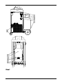
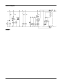
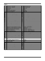
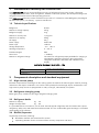
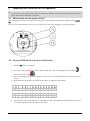
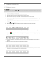
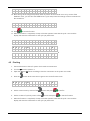
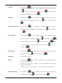
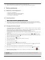
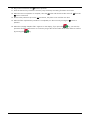
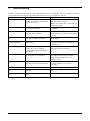
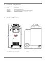
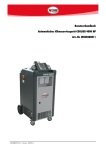
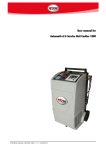
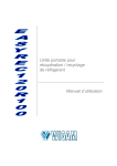
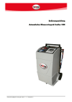
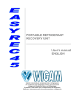
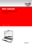
User’s manual
COOLIUS 4000 HP automatic a/c service unit
Art.-No.W050200011
2154-ENG / Version 02/2014
CONTENTS
Safety precautions ................................................................................................................................................................... 2
Layout drawings ..................................................................................................................................................................... 3
Hydraulic diagram .................................................................................................................................................................. 5
Electric diagram ...................................................................................................................................................................... 6
Legend .................................................................................................................................................................................. 7
1
Introduction to recovery unit COOLIUS-HP ........................................................................................................................ 8
1.1
Technical specifications ................................................................................................................................................ 8
2
Components description and standard equipment.............................................................................................................. 8
2.1
High vacuum pump ..................................................................................................................................................... 8
2.2
Refrigerant charging pump ........................................................................................................................................... 8
2.3
Refrigerant bottle ......................................................................................................................................................... 8
2.4
Distiller/Separator........................................................................................................................................................ 8
2.5
Compressor ................................................................................................................................................................ 9
2.6
Filters drier .................................................................................................................................................................. 9
2.7
Flexible hoses .............................................................................................................................................................. 9
2.8
Quick coupler valves .................................................................................................................................................... 9
2.9
Printer ......................................................................................................................................................................... 9
2.10
Control module ........................................................................................................................................................... 9
3
Preparing unit COOLIUS-HP for operation ...................................................................................................................... 11
3.1
Checking the vacuum pump oil level ........................................................................................................................... 11
3.2
Turning COOLIUS-HP unit on for the first time ............................................................................................................. 11
3.3
Filling refrigerant into the internal bottle ...................................................................................................................... 12
4
Using unit COOLIUS-HP .............................................................................................................................................. 13
4.1
Refrigerant recovery ................................................................................................................................................... 13
4.2
Vacuum + Vacuum Test ............................................................................................................................................. 14
4.3
Olio / Uv – Refrigerant charge .................................................................................................................................... 14
4.4
Automatic cycle ......................................................................................................................................................... 16
4.5
Flushing .................................................................................................................................................................... 18
4.6
Checking the A/C system operating pressures .............................................................................................................. 19
4.7
Disconnecting the unit from the A/C system ................................................................................................................. 19
4.8
Setting Menu ............................................................................................................................................................. 19
5
Service procedures ...................................................................................................................................................... 21
5.1
Emptying the internal refrigerant bottled ...................................................................................................................... 21
5.2
“Zero” scale check ..................................................................................................................................................... 21
6
Routine maintenance ................................................................................................................................................... 22
6.1
Material for routine maintenance ................................................................................................................................ 22
6.2
Periodic operations .................................................................................................................................................... 22
6.3
Changing the vacuum pump oil .................................................................................................................................. 22
6.4
Replacing the filter drier ............................................................................................................................................. 23
7
Troubleshooting .......................................................................................................................................................... 25
8
Accessories and spare parts .......................................................................................................................................... 26
9
Weight and dimensions ................................................................................................................................................ 26
1 - 32
Safety precautions
This equipment is designed for trained personnel only, who must know the refrigeration
fundamentals, cooling systems, refrigerants and possible damage that pressurized equipment may
cause.
Only use refrigerant R134a. The unit must not be used with a different refrigerant than the one it has
been designed for.
Carefully read the instructions contained in this manual; strict
observance of the procedures
described is fundamental to the operator’s safety, the perfect state of the unit and constant
performances as declared.
The unit must always work under the operator’s direct supervision
Before performing any operation, make sure that the hoses used for connections have been
previously evacuated and that they do not contain non-condensable gases.
Avoid skin contact; the low boiling temperature of the refrigerant (about -30°C) can cause freezing.
Avoid breathing refrigerant vapours.
It is recommended to wear suitable protections like safety glasses and gloves; contact with refrigerant
may cause blindness and other personal injuries.
Do not smoke near the unit and do not operate near open flames and hot surfaces; the high
temperatures decompose the refrigerant releasing toxic and caustic substances which are hazardous
for the operator and the environment.
Always make sure that the unit is connected to a suitably protected mains supply provided with an
efficient earth connection.
Before performing maintenance operations or when the unit will not be used for a long period of
time, turn the unit off by turning the main switch to 0 and disconnect the power supply cord;
absolutely follow the sequence of operations.
Operate the unit only in locations with suitable ventilation and a high number of air changes.
Before disconnecting the unit, make sure that the cycle has been completed and that all valves are
closed in order to avoid release of refrigerant to the atmosphere
Never fill any tank with liquid refrigerant to more than 75% of its maximum capacity.
During operations avoid release of refrigerant to the environment; this precaution is required by
international environmental standards and is essential to avoid difficult leak detection in a refrigerant
polluted environment.
Protect the unit from dripping.
Do not expose the unit to direct sunlight, rain and to the inclemency of the weather.
Do not modify the calibration of safety valve and control systems.
If you recover refrigerant from a cooling system equipped with a water evaporator and/or condenser,
it is necessary to drain water from the evaporator and/or condenser or to keep the circulation pump
running during the entire recovery operation in order to avoid frosting.
Disconnect the unit from the power supply if not used.
General information
Perform a good vacuum cycle before charging refrigerant into the system!
Perform the refrigerant charging phase after having charged oil or UV!
Empty the used oil bottle before starting the recovery phase!
WARNING!
If you do not pay attention to the above safety precautions, you could damage the recovery unit and the
car A/C system!
2 - 32
Layout drawings
Picture 1
3 - 32
Picture 2
4 - 32
Hydraulic diagram
Picture 3
5 - 32
Electric diagram
Picture 4
6 - 32
Legend
1
Solenoid valve – oil discharge line
48
Oil discharge bottle
2
Solenoid valve - recovery line
49
Refrigerant charge pump
4
Solenoid valve - vacuum line
50
Oil/UV charging bottle
6
Vacuum pump
51
Plastic cover
7
Compressor
52
Frame
9
Compressor starting condenser
53
Front door
10
Vacuum pump oil filler plug
54
Power cable
11
Vacuum pump sight glass
55
HIGH quick coupler
12
Vacuum pump oil drain plug
56
LOW quick coupler
13
Solenoid valve - refrigerant charging line
57
Manual discharge valve on the distiller
14
Heater belt with thermostat on the bottle
59
Oil return hose to compressor
15
Pressure transducer
60
Vibration damping feet on the scale
16
Spring for heater belt
61
Condenser with fan
17
Safety pressure switch
62
Remote control witch for recovery compressor
18
Main power switch
64
Thermal paper roll
19
Solenoid valve - oil/UV charging line
65
Fuse on outlet (10A)
20
Solenoid valve - pressure return to compressor
66
Distiller coil inlet tube
21
Liquid valve on the bottle
67
Distiller coil outlet tube
22
Refrigerant charge hose (bottle-pump)
68
Rear door
23
Vapour valve on the bottle
69
Handle
24
Power outlet (with fuse)
70
Load cell - 100 kg (refrigerant)
25
Condenser / bottle connecting hose
71
Load cell - 5 kg (oil discharge)
26
Capillary hose connecting LOW valve to LP gauge
72
Load cell - 5 kg (oil charge)
27
Capillary hose connecting HIGH valve to HP gauge 73
Control board
28
Refrigerant charge hose (pump-valve block)
74
Check valve - recovery line
29
Oil discharge capillary tube
75
Check valve – compressor delivery line
30
Refrigerant charge pump motor
76
Check valve – refrigerant charging line
31
Complete refrigerant bottle
77
Check valve – oil discharge line
32
Front wheel with brake
78
Check valve – oil charging line
33
Rear wheel Ø 250
79
Check valve - compressor delivery line (condenser)
34
Safety pressure switch on refrigerant charging line
80
Filter drier
35
Oil injection capillary tube
81
Filter drier
36
Hose - pressure return to compressor
82
Manual valve - LOW
37
Compressor/compressor oil separator connecting
hose
83
Manual valve - HIGH
38
Valves assembly - distiller connecting hose
84
LP gauge
39
Safety switch capillary hose
85
HP gauge
40
Vacuum pump hose
86
Printer
41
Compressor suction hose
87
Electric feeder
42
Distiller/filter F1 connecting hose
88
Service connection for compressor evacuation
43
Distiller / separator
89
Bottle service connection
44
Distiller/filter F2 connecting hose
90
Bottle service connection (1/4” SAE)
45
Oil separator – complete compressor
91
LOW flexible hose
46
Flow regulation valve with hoses
92
HIGH flexible hose
47
Handle support
93
Safety valve
7 - 32
1
Introduction to recovery unit COOLIUS-HP
Unit COOLIUS-HP permits quick and efficient recovery of refrigerant from the A/C system, refrigerant
recycling, system evacuation, check for tightness, additive or lubricant injection, the subsequent charge with
refrigerant and measurement of the operating pressures.
Unit COOLIUS-HP permits to control all functions by means of 3 electronic scales (Refrigerant, Discharged
Oil from A/C system, new Oil/Uv), 1 pressure transducers.
1.2 Technical specifications
Refrigerant
Maximum storage capacity
R134a
40 kg
Refrigerant supply
4 kg
Maximum recovery rate
1,0 kg/min
Maximum oil capacity
500 g
Oil supply
50 g
Power supply
230/1/50
Power input
1400 W
Storage temperature
-10 ÷ +50 °C
Working temperature
0 ÷ 40 °C
Protection degree
Noise level
IP24
< 70dB (A)
Maximum refrigerant charge
The maximum refrigerant quantity available for charging is
calculated by subtracting 4 kg from the weight of the
refrigerant contained in the bottle and indicated on the
display
max kg for charging = kg in bottle - 4 kg
2
Model
Couplers and connections
COOLIUS-HP
1/4” SAE with quick couplers
Components description and standard equipment
2.1 High vacuum pump
Essential component for extracting from the cooling system the residues of technical gases used for pressing,
ambient air and vapour contained in it as well as water possibly formed through vapour condensation. The
high vacuum pump the unit is equipped with is rotary vane type, lubricated by oil injection.
2.2 Refrigerant charging pump
Rotary gear pump enables to have high refrigerant charging rates
2.3 Refrigerant bottle
Maximum capacity
Weight of empty bottle
kg
kg
40
22
It is provided with two connections, one of which with tube (liquid refrigerant) and one without tube (vapour
refrigerant), safety valve and heater belt with thermostat. The non condensable gases discharge is controlled
automatically by the software.
2.4 Distiller/Separator
Single body construction, featuring:
Distillation chamber with automatic flow control
Separating chamber for the oil removed from recovery compressor and return
8 - 32
Heat exchanger chamber outlet gas / recovered refrigerant
2.5 Compressor
Compressor is of the hermetic type
2.6 Filters drier
Filters are anti-acid and have a water absorption capacity of 40 g of water. The can filter more than 300 kg
of fluid.
2.7 Flexible hoses
Their flexibility assures easy connection in any situation. They withstand A/C system operating pressures and
maintain their passage section even when operating in vacuum.
Unit COOLIUS-HP features hoses with quick coupler valves.
Inner and outer hoses are in conformity with SAE J2916 standard.
2.8 Quick coupler valves
Mounted on the hose ends and provided with a coloured operating ring (blue = low pressure, ref. 91; red =
high pressure, ref. 92) for quick identification.
2.9 Printer
The printer allows to print a report on paper with the values programmed by the operator and executed by the
unit, with the possibility to re-print the report. Use paper (cod. n° 0764 95 002) as spare part.
2.10 Control module
The unit is equipped with a large 7”color display, on which you will find the following information (Picture 5):
Micro SD-Card
connector
Recovery function
Oil Charge /
Refrigerant charge
function
Vacuum function
Arrow UP
Arrow DOWN
Access to Menu
Exit key (Back)
Auto function
Start / Stop key
Picture 5
9 - 32
Access to the Refrigerant Recovery function
Access to the Vacuum function
Access to the Oil charge/ Refrigerant charge function
Standby – Access to the Menu for the modification of the unit’s settings parameters
During a function setting – Back to the standby screen (during refrigerant charge,
press for more than 1 second)
During Refrigerant charge setting – Access to the Database
Standby – Access to the Automatic function
During a function – Start and end of the function
During a function under way – if pressed for more than 3 seconds, it stops the
function for emergency
When pressed singly – enables to shift through the various ranges and modify the
numerical values
When pressed both at the same time – Start of the Flushing function
10 - 32
3
Preparing unit COOLIUS-HP for operation
WARNING!
The presence of the synoptic sticker does not exempt the operator from carefully reading this manual and
strictly observing the described procedures.
3.1 Checking the vacuum pump oil level
Before checking the oil level, the unit must be placed on a level surface and its power supply must be turned
off.
The user must check that the vacuum pump oil level covers half of the sight glass (see drawing below).
3.2 Turning COOLIUS-HP unit on for the first time
1. Place the 87 switch on position 1
2. The unit will automatically ask for the interface language; select the language by means of the
arrows and confirm with
.
3. Then, the zeroing of all the scales will start. The process is completely automatic and will take about 1
minute.
4. At the end of the procedure, the values of the scales will appear on the display.
R
1
3
4
a
1
0
:
3
4
0
0
.
0
0
0
k
g
Ξ
8
/
1
0
/
1
2
▼
0
g
▲
0
g
Ξ
Standby screen 1
O
l
i
o
i
n
O
l
i
o
o
u
t
Standby screen 2
5. The next times you will turn the unit on, the display will show the software and hardware version of the
unit and the standby screen will appear right away.
11 - 32
3.3 Filling refrigerant into the internal bottle
The unit is supplied with no refrigerant inside. It is thus necessary to follow the below procedure to fill
the exact quantity of refrigerant into the refrigerant bottle.
1. Place the bottle containing refrigerant so that liquid refrigerant will come out (bottle with tube upright,
bottle without tube upside down).
2. Connect the male LP connection (supplied in the kit) to the refrigerant bottle (only in case the bottle is
not equipped with a connection).
3. Connect the quick coupler ref. 56 (blue) to the bottle containing refrigerant. Open the hand-wheel of
the coupler.
4. Open the 82 valve and close the 83 valve.
5. Make sure that the valve on the external bottle is closed.
6. Press the Vacuum key on the control module
7. Set a vacuum time of 5 minutes by means of the
V
T
i
m
a
c
u
u
arrows
m
e
8. Press the
5
‘
key to start the function and wait for the end of it (beep)
9. Once the vacuum cycle is completed and you are back in the standby screen, slowly open the valve
of the bottle containing refrigerant
10. Press the Recovery key
11. Set the refrigerant quantity to recover (we suggest 5.000 kg) by means of the
R
R
1
3
4
12. Press the
e
c
o
v
a
e
r
y
5
.
0
0
0
k
arrows
g
key to start the function.
13. Wait until the recovery cycle is completed. A beep will let the user know that the cycle is over and the
quantity of recovered refrigerant will be displayed.
IMPORTANT!
In this moment, there is refrigerant in the hoses. Continue the procedure in order to prevent gas
dispersion in the environment
14. Close the valve on the bottle containing refrigerant
15. Start a new recovery cycle set on ALL
R
R
1
3
16. Press the
4
e
c
o
v
e
a
r
y
A
L
L
key to start the function.
17. Wait until the recovery cycle is completed; a beep will let the user know that the cycle is over and the
quantity of recovered refrigerant will be displayed.
18. Disconnect the hose from the bottle
12 - 32
4
Using unit COOLIUS-HP
4.1 Refrigerant recovery
WARNING!
During recovery, regulate the 82 and 83 valves on the control panel, so that the input pressure never rises
over 5 bar
1. Turn on the engine with closed hood
2. Turn the air-conditioner on and have it run for some minutes
3. Open the hood and set the air-conditioner fan to maximum speed
4. Have the vehicle engine run slowly (800 - 1200 revolutions/min) for a few minutes
5. Turn the vehicle engine off and have the air-conditioner fan run at maximum speed and start
recovery operations
the
6. Connect the hoses to the A/C system which needs a maintenance. Open the hand-wheels on the
couplers.
7. Turn the 87 switch to position 1.
8. Open the 82 and 83 valves according to how the connection on the system was made
9. Press the Recovery key
R
R
1
3
4
e
c
o
v
e
r
a
y
A
L
L
10. The unit sets the recovery function on ALL by default: in this way, the unit recovers all the refrigerant
there is inside the car.
11. Press the
key to start the function. During the recovery cycle, the recovered refrigerant quantity
appears on the display.
R
1
R
e
c
3
4
a
.
u
n
d
e
r
0
.
0
w
a
y
0
0
k
g
12. In case of emergency, it is possible to leave the function by pressing the STOP key for more than 3
seconds.
13. During the cycle, the unit performs the automatic oil discharge
O
i
l
d
i
s
c
h
a
r
g
e
0
g
14. Wait until the recovery cycle is completed; a beep will let the user know that the cycle is over and the
quantities of recovered refrigerant and oil will be displayed.
R
1
3
4
O
l
i
o
a
1
O
u
t
.
1
0
0
k
1
0
g
13 - 32
g
WARNING!
Do not pollute environment with oil; it is a special waste and must be disposed of according to the
regulations in force.
4.2 Vacuum + Vacuum Test
1. Connect the hoses to the A/C system which needs a maintenance
2. Turn the 87 switch to position 1.
3. Open the 82 and 83 valves according to how the connection on the system was made
4. Press the Vacuum key
V
a
c
u
T
i
m
e
u
m
3
5. Set a vacuum time by means of the
0
‘
arrows. We suggest a vacuum time of at least 30 minutes.
6. Press the
key to start the function. (In case of emergency, it is possible to leave the function by
pressing the STOP key for more than 3 seconds)
7. When the vacuum cycle is over, the test phase starts to check the possible presence of leaks in the A/C
system.
8. When the vacuum test is over, or if there are leaks, a beep will inform the operator. The display will
show the information on the cycle just performed.
V
a
c
u
u
m
V
a
c
u
u
m
3
t
e
s
t
0
‘
O
K
4.3 Olio / Uv – Refrigerant charge
1. Connect the hoses to the A/C system which needs a maintenance
2. Turn the 87 switch to position 1.
3. Open the 82 and 83 valves according to how the connection on the system was made
WARNING!
Always perform the charging function with a system which has been previously evacuated. In case the
evacuation has not been effected correctly, the unit will inform the user by means of an alarm
4. Press the Charge key
5. The operator will be asked to select the type of charge: whether it will be effected through a single
hose (blue or red) or whether it will be effected through both hoses. This enables the unit to calculate
the correct value of the pre-charge (when it is set).
2
1
h
h
o
o
s
s
e
e
s
L
+
▲
▼
H
14 - 32
6. Confirm with
O
i
l
O
i
l
and then the screen for setting the oil/UV quantity will appear
M
a
x
S
A
M
E
1
5
0
g
7. The units sets SAME by default. During the oil injection phase, the same quantity of oil that has been
recovered during recovery will be re-injected into the system.
8. The units checks the maximum quantity that can be charged and indicates it on the second line of the
display.
9. In case you would like to set a different quantity than SAME, you can modify it the quantity by means
of the
arrows and confirm with
.
WARNING!
If you do not want to inject oil/UV, set the value on 0 grams
Suggested quantities for refilling the A/C system with oil
According to the type of A/C system component you have replaced, you need to fill in the lubricant
quantity indicated below, even if no oil has been extracted during recovery.
Evaporator:
50cc
Condenser:
30cc
Filter:
10cc
Pipes:
10cc
In any case the operator must follow the instructions of the A/C system manufacturer.
1. Press
and the screen for setting the refrigerant quantity will appear
R
1
3
4
a
D
a
t
a
b
2. If you press
0
a
s
,
3
0
0
k
g
▲
▼
e
on the first line, the refrigerant quantity can be set manually, by means of the
arrows and confirming with
R
1
3
M
a
x
4
a
0
,
3
0
0
k
g
4
,
6
6
5
k
g
3. Otherwise, on the second line, you can gain access to the database and choose between Standard
Database (containing the main cars on the market) and Personal Database (created by the user).
D
b
S
t
a
n
d
a
r
d
D
b
P
e
r
s
o
n
a
l
15 - 32
4. After having set the refrigerant quantity either by means of the manual menu or by means of the
database menu, you will have the
the second line.
*
S
t
a
r
t
..
..
..
..
..
..
5. Press
..
screen (cycle start) where the settings will be summarized on
S
t
a
r
t
*
..
..
..
..
..
..
..
..
..
to start the function.
WARNING!
The refrigerant charge cycle is performed “by steps” in order to reach a high precision. You may hear
subsequent “clicks” inside the unit during this phase.
6. When the function is completed, a beep will let the operator know that the cycle is over and the
display will show the information on the cycle just performed.
R
1
3
O
i
l
4
a
0
i
,
3
0
n
0
k
5
g
g
4.4 Automatic cycle
1. Connect the hoses to the A/C system which needs a maintenance
2. Turn the 87 switch to position 1.
3. Open the 82 and 83 valves according to how the connection on the system was made
4. Press the Auto key
WARNING!
At the cycle start, the unit will check the available volume inside the bottle. In case the total weight on the
scale exceeds 8.000 kg, COOLIUS-HP unit will display the following alarm signal: “Check bottle weight”.
The same check is performed for the oil quantity in the “New Oil” dosimeter
5. The operator will be asked to select the type of charge: whether it will be effected through a single
hose (blue or red) or whether it will be effected through both hoses. This enables the unit to calculate
the correct value of the pre-charge (when it is set).
2
h
o
s
e
1
h
o
s
e
6. Confirm with
i
m
L
+
▲
H
▼
and then the screen for setting Vacuum will appear
V
T
s
a
c
u
u
m
e
3
16 - 32
0
‘
7. Modify the vacuum time by means of the
arrows and confirm with
.
WARNING!
The function of refrigerant recovery will be performed in case refrigerant is detected in the A/C system
when connecting the unit to it.
8. Now the screen for setting the oil/UV quantity appears
O
i
l
O
i
l
S
M
a
x
A
M
E
1
5
0
g
9. The units sets SAME by default. During the oil injection phase, the same quantity of oil that has been
recovered during recovery will be re-injected into the system.
10. The units checks the maximum quantity that can be charged and indicates it on the second line of the
display.
11. In case you would like to set a different quantity than SAME, you can modify it the quantity by means
of the
arrows and confirm with
.
WARNING!
If you do not want to inject oil/UV, set the value on 0 grams
Suggested quantities for refilling the A/C system with oil
According to the type of A/C system component you have replaced, you need to fill in the lubricant
quantity indicated below, even if no oil has been extracted during recovery.
Evaporator:
50cc
Condenser:
30cc
Filter:
10cc
Pipes:
10cc
In any case the operator must follow the instructions of the A/C system manufacturer.
12. Press
and the screen for setting the refrigerant quantity will appear
R
1
3
4
a
D
a
t
a
b
13. If you press
0
a
s
1
3
M
a
x
3
0
0
k
g
▲
▼
e
on the first line, the refrigerant quantity can be set manually, by means of the
arrows and confirming with
R
,
4
a
.
0
,
3
0
0
k
g
4
,
6
6
5
k
g
14. Otherwise, on the second line, you can gain access to the database and choose between Standard
Database (containing the main cars on the market) and Personal Database (created by the user).
17 - 32
D
b
S
t
a
n
d
a
r
d
D
b
P
e
r
s
o
n
a
l
15. After having set the refrigerant quantity either by means of the manual menu or by means of the
database menu, you will have the START screen (cycle start) where the settings will be summarized on
the second line.
*
S
t
a
r
t
..
..
..
..
..
..
16. Press
..
S
t
a
r
t
*
..
..
..
..
..
..
..
..
..
to start the function.
17. When the function is completed, a beep will let the operator know that the cycle is over and the
display will show the information on the cycle just performed.
R
1
3
4
a
1
O
i
l
V
a
c
u
u
m
V
a
c
u
u
m
O
i
l
R
1
3
O
4
u
.
1
t
t
e
a
s
0
0
0
k
g
1
0
g
.
3
0
‘
O
K
t
.
7
1
0
g
.
0
0
k
g
T
4.5 Flushing
1. Connect the hoses to the A/C system which needs a maintenance
2. Turn the 87 switch to position 1.
3. Open the 82 and 83 valves according to how the connection on the system was made
4. Press the
arrows at the same time to gain access to the function menu
V
a
c
u
u
m
F
l
u
s
h
.
1
c
y
c
l
5. Set the vacuum time by means of the
6. Set the number of cycles by means of the
e
s
0
‘
3
arrows and press
arrows and press
to confirm
to start the function
7. When the function is completed, a beep will let the operator know that the cycle is over and the
display will show the information on the cycle just performed
18 - 32
WARNING!
At the cycle start, the unit will check the available volume inside the bottle. In case the total weight on the
scale is lower than 10.000 kg, COOLIUS-HP unit will display the following alarm signal: “Check bottle
weight”. It is indeed necessary to have at least 10.000 kg of refrigerant inside the bottle to perform this
function.
4.6 Checking the A/C system operating pressures
1. Make sure that the 82 and 83 valves are closed and that the 87 switch is on position 0
2. Connect the 91 hose to the A/C system low pressure side
3. Connect the 92 hose to the A/C system high pressure side
4. Start the compressor of the A/C system
5. Read the pressure and its corresponding evaporation temperature on the 84 pressure gauge
6. Read the pressure and its corresponding condensing temperature on the 85 pressure gauge
7. Compare the values with the ones suggested by the cooling system manufacturer
4.7 Disconnecting the unit from the A/C system
At the end of the charging function or at the end of the checking of the operating pressures, some
liquid refrigerant is still inside the hoses. In order to minimize the residual quantity of refrigerant inside
the hoses, follow the below procedure:
1. Close the hand-wheel of the quick coupler ref. 55 (red) and disconnect the 92 hose from the A/C
system while the A/C system compressor is running
2. Make sure that the 91 hose is connected to the A/C system
3. Open the 82 and 83 valves in order to have all the liquid refrigerant sucked by the A/C system
4. As soon as the pressures on the high and low pressure gauges are the same and do not exceed 2÷3
bar, close the hand-wheel of the quick coupler ref. 56 (blue) and disconnect the 91 hose from the A/C
system
5. Perform a recovery cycle to suck the remaining refrigerant from the hoses so that the unit is
immediately ready for the next operation
6. Turn the unit off (87 switch in position 0)
7. Close the 82 and 83 valves
8. Carefully screw the protective caps on the A/C system service valves
9. Using a leak detector, check the A/C system for leaks
WARNING!
The introduction of tracer additives and the following use of a UV leak detector will make it easier to
locate the point of the possible leak in the future
4.8 Setting Menu
If you press the
key in the standby screen, you can gain access to the setting menu of the unit.
19 - 32
Car plate
By pressing the
key, it is possible to type the plate of the car on which
you are making maintenance. You can modify each single field by means of
the
arrows and move forward by means of the
up to the last field available with the
Language
By pressing the
key.
key, it is possible to change the language of the unit.
Shift through the languages by means of the
Unit of measurement
key. Move forward
By pressing the
arrows and confirm with
key, it is possible to modify the unit of measurement
(INTERNATIONAL or IMPERIAL). Shift by means of the
keys and confirm
with
Inner Database
By pressing the
key, it is possible to make your own database. Shift to
the field you want to modify by means of the
. Modify each digit by means of the
keys and confirm with
arrows and confirm with
type the value of the refrigerant charge by means of the
. Then
arrows and
confirm with
Date and Hour
By pressing the
key, it is possible to set the date and hour. Modify each
value by means of the
arrows and confirm with
Calibration
See section 5.1 below
Service
By pressing the
key, it is possible to make some service operations using
several keys combinations
Password: Recovery - Down - Charge - Vacuum: Cancellation of all the data
saved on the SD-Card.
Password: Vacuum - Charge - Down - Up : total zeroing of all the scales
Contrast regulation
By pressing the
key, it is possible to modify the value of the display
contrast by means of the
20 - 32
arrows and confirming with
.
5
Data exportation
By pressing the
key, it is possible to export the services performed by the
unit into the SD-card (from inside memory to SD-Card). The unit creates a .txt
file to import into your own PC. In case the message “ERROR CODE 08”
appears, re-start the unit and try again the exportation procedure.
To cancel all the data saved in the memory card, follow the procedure
explained at “Service”
Workshop data
By pressing the
key, it is possible to modify the 6 lines available on the
report to write some information about your own workshop. Once the
information have been written, they will be printed on each report.
Service procedures
5.1 Emptying the internal refrigerant bottled
1. Make a vacuum of at least 15 minutes in an external bottle able to contain the refrigerant there is in
the internal bottle of the unit.
2. Remove the rear closing door ref. 68.
3. By means of the HP quick coupler ref. 55 (red), connect the 92 hose to the 89 service connection of
the internal bottle (after having removed the protection cap).
4. Connect a service hose (with valve opener) between the valve of the external bottle (previously
evacuated) and the 90 service connection of the internal bottle.
5. Close the valve ref. 23.
6. Open the 83 valve and close the 82 valve.
7. Turn the hand-wheel of the coupler ref. 55 (red) to open it
8. Start the Recovery “ALL” automatic function to empty the internal bottle completely; recovery will stop
automatically when there will be no more refrigerant inside the unit.
9. Disconnect the service hose from the 90 service connection and remount the protection
10. Start the Vacuum function by opening the 83 valve on the control panel and perform vacuum and
vacuum test for about 30 minutes
11. At the end of the vacuum and vacuum test function, disconnect the 92 hose from the 89 service
connection, remount the protection cap and proceed with the scale calibration (see section 5.1.1)
12. At the end of operations, re-open the valve ref. 23 and reassemble the rear door.
5.2 “Zero” scale check
The following procedure allows to zero all the scales of the unit at the same time. Such procedure must
be performed when the scales do not show the correct value of 0 when the unit is completely empty.
1. Make sure that the refrigerant bottle of the unit and the oil bottles are empty.
2. Wait at least 2 minutes so that the bottle/scale assembly stabilizes before proceeding.
3. Press the
key
4. Select “Service” by means of the
5. Confirm by pressing the
arrows.
key.
21 - 32
6. Press the following keys in succession: Vacuum, Charge, Down, Up.
7. When coming back to the standby screen, all the scales will be placed on the value 0.
6
Routine maintenance
6.1 Material for routine maintenance
n°1
n°1
n°1
n°1
filter direr, model XH412
bottle mineral oil for vacuum pump, model K1L
bottle of oil for compressor, model SW32
kit of gaskets, model G19020
6.2 Periodic operations
1. Check all swivel connections for tightening every 10 operations
2. Check the vacuum pump oil level; the oil must be changed at least every 100 hours of operation or
once every six months even if the unit is not used frequently. The pump must be off when checking the
oil level. Anyway, the unit will inform the operator when the oil must be changed.
6.3 Changing the vacuum pump oil
The vacuum pump oil must be change whenever the message “Change vacuum pump oil” appears
on the display when the unit is turned on.
The oil also needs to be changed whenever it becomes cloudy. Contaminated oil reduces vacuum
pump performances and irreversibly damages its mechanical components.
All draining and refilling operations must be performed when the pump is turned off.
To avoid reduction of the pump efficiency and to maintain its performances, use only K1L oil for
maintenance.
1. Before draining the oil, have the pump run for at least 10 minutes with the 82 and 83 valves closed.
2. Turn the recovery unit off by turning the 87 switch to position 0 and disconnect the power cord; strictly
observe the sequence of operations
3. Remove the front door ref. 53 of the unit
4. Unscrew the drain plug ref. 12 located at the bottom of the pump
5. Completely drain the oil
6. Screw the drain plug on again
7. Unscrew the filler plug ref. 10 situated on top of the pump
8. Slowly refill the pump with oil until the level covers half of the sight glass (ref. 11) located on the side
of the pump
9. Screw the oil plug on again and re-install the previously removed panel again
10. When the oil change procedure is completed, turn the unit on by turning the 87 switch to position 1
11. When the message “Change vacuum pump oil” appears on the display, if you press the
then the counter is set at zero.
WARNING!
Do not pollute environment with oil; it is a special waste and must be disposed of according to the
regulations in force
22 - 32
key,
6.4 Replacing the filter drier
The filter must be replaced whenever the message “Replace filter” appears on the display when the
unit is turned on.
The replacement must be effected at the end of the recovery cycle.
1. Turn the recovery unit off by turning the 87 switch to position 0 and disconnect the power cord; strictly
observe the sequence of operations
2. Remove the rear door of the unit
3. Remove the old filters ref. 80, 81 by unscrewing connections ref. 41, 42 and 44
WARNING!
This equipment is designed for trained personnel only, who must know the refrigeration fundamentals,
cooling systems, refrigerants and possible damage that pressurized equipment may cause.
WARNING!
Do not pollute environment with the used filters; it is a special waste and must be disposed of according to
the regulations in force.
4. Remove the gaskets from inside the hoses (ref. 41, 42 and 44)
5. Install new gaskets
6. Install new filter driers
7. Remove the protective cap on the 88 connection
8. Connect the valve ref. 56 to the 88 service connection
9. Open the 82 valve and close the 83 valve
23 - 32
10. Plug in the unit and turn the 87 switch to position I
11. Press the Vacuum key to start the vacuum pump and keep evacuating for about 30 minutes
12. When the vacuum operation is complete, close the 82 valve and disconnect the valve ref. 56 from the
88 service connection
13. Remount the protective cap on the 88 connection, the plastic cover and the rear door
14. When the filter replacement procedure is completed, turn the unit on by turning the 87 switch to
position I
15. When the message “Replace filter” appears on the display, if you press the
key, you enter the
procedure for filter replacement. It is necessary to type the serial number of the filter and then confirm
by pressing the
key.
24 - 32
7
Troubleshooting
If there is a problem in the unit, this will be displayed with an alarm message. You can recognize the alarm
screen easily from the symbol on the left upper side of the screen and from the red led.
Message
Type of error
Solution
No refrigerant
After connecting the unit to the A/C
system, the values of the pressure
sensors do not vary
Make sure that the unit is connected to
the A/C system correctly.
Refrigerant bottle full
The refrigerant bottle has reached
its maximum capacity
Provide to empty the bottle from the
refrigerant
Max time reached
The maximum time to complete the
cycle has been reached
Re-start the cycle and in case the same
problem occurs, contact the after-sales
service.
Oil discharge bottle
full
The oil discharge bottle has
reached its maximum capacity
Provide to empty the bottle from the oil
discharged
Max number of
attempts reached
The recovery cycle has started more
than 3 times
Re-start the recovery cycle and if the
problem still occurs, contact the aftersales service
Presence of refrigerant
The unit has found refrigerant when
starting the vacuum function.
Presence of refrigerant inside the
A/C system
Perform a recovery cycle before
starting the vacuum function
Vacuum leak
During the vacuum test, there was
an abnormal rise of pressure
The A/C system is not completely tight.
Provide to find the leak in the A/C
system and proceed with a new
vacuum cycle.
Max pressure
The maximum pressure inside the
recovery circuit has been reached.
Make sure that all connections on the
recovery delivery line are open
correctly.
Replace filter
The filter capacity is almost full
Provide to replace the filter soon
Change vacuum pump
oil
The vacuum pump oil must be
changed
Provide to changed the vacuum pump
oil
Error code 08
Error during the record of the SDcard
Re-start the unit
25 - 32
Make sure that the A/C system has no
refrigerant inside
8
9
Accessories and spare parts
Code
Description
14015013
12002003
12002006
14020014001
XH412 anti-acid filter drier
K1 L mineral oil for vacuum pump, bottle of 1.000cc
Ester oil for compressor
G19020 kit of gaskets for 1/4sae hoses - 10pcs
Weight and dimensions
Net weight with empty internal bottle
140 kg
26 - 32
27 - 32
COOLIUS 4000 HP produced by Wigam spa for WOW! Würth Online World GmbH
Wigam spa reserves the right to discontinue, or change at any time specifications or designs without notice
and without incurring obligations according to her policy of always improving her products.
Layout : WIGAM S.p.A.
Printed in Italy
First edition : December 2012
28 - 32
WOW! Würth Online World GmbH
Schliffenstraße Falkhof
74653 Künzelsau
+49 (0) 7940-981 88 0
+49 (0)7940-981 88 1098
[email protected]
http://www.wow-portal.com
2154-ENG /Version 02/2014