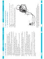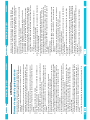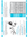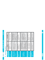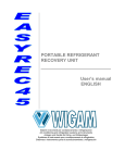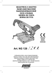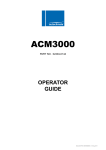
1
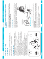
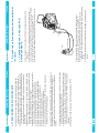
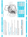
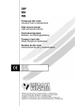
Loc.Spedale 10/b 52018 Castel San Niccolò (AR) ITALY
Tel. ++39-0575-5011 Fax. ++39-0575-501200
www.wigam.com - [email protected]
Manuale istruzioni
UNITÀ PORTATILE PER
RECUPERODI REFRIGERANTE
MANUALE D’USO
ITALIANO
Realizzazione: WIGAM S.p.A. Stampato in Italia
Prima edizione: Sett. 2009
La WIGAM S.p.a. si riserva il diritto di modificare i
dati e le caratteristiche contenute nel presente
manuale, senza obbligo di preavviso, nella sua
politica di costante miglioramento dei prodotti.
EASYREC120
SOMMARIO
MANUALE D’USO
ITALIANO
1
11.Troubleshooting············································································16
10.Caratteristiche tecniche································································15
9.Riarmo del pressostato di massima················································15
8.2.Interventi periodici di manutenzione ordinaria··································14
8.1.Materiale necessario······································································14
8.Manutenzione ordinaria··································································14
7.2.Procedura di raffreddamento durante il recupero······························14
7.1.Preparazione per la procedura di raffreddamento·····························13
7.Procedura di raffreddamento della bombola di recupero·················13
6.2.Trasferimento del refrigerante·························································12
6.1.Avvertenze····················································································11
6.Trasferimento del refrigerante con il metodo Push-Pull···················11
5.2.Funzione “purge”··········································································10
5.1.Avvertenze····················································································10
5.Procedura “Self-purge”··································································10
4.2.Recupero refrigerante····································································8
4.1.Avvertenze····················································································8
4.Recupero del refrigerante dall’impianto A/C····································8
3.Pannello di comando········································································7
2.3.Manometri······················································································6
2.2.Filtro······························································································6
2.1.Compressore di recupero·································································6
2.Dotazione standard e descrizione delle parti componenti················6
1.Introduzione al sistema di recupero EASYREC120····························6
Norme di sicurezza e linee guida per l’utilizzo·····································4
Schema elettrico·················································································3
Schema idraulico················································································ 2
EASYREC120
Pressostato di sicurezza
Pressovacuostato
SP1
SP2
Recover/Purge Valvola Recupero / Purge
OUTPUT valve Valvola su linea alta pressione
Valvola su linea bassa pressione
Manometro mandata
M2
INPUT valve
Manometro aspirazione
M1
ITALIANO
Condensatore
Ventola
3
Compressore
Valvola 2 per sistema distillatore
Valvola 1 per sistema distillatore
2
1
V2
V1
2
CV1 Valvola di ritegno su linea di mandata
MANUALE D’USO
Schema idraulico
EASYREC120
Presa di corrente
Interruttore principale
Dispositivo di protezione per sovraccarico
Motore del compressore
Ventola assiale
Relé
Relé
Relé
Interruttore centrifugo
Condensatore di avviamento
XS
SA
FR
M1
M2
K1
K2
K5
SR
C1
Trasformatore elettronico
Condensatore di marcia
Interruttore By-Pass
ITALIANO
ST
Termoprotezioni del motore
3
HL2 Indicatore di protezione bassa pressione
HL1 Indicatore di protezione alta pressione
SK
SB1 Pulsante di avviamento
SP2 Pressovacuostato
SP1 Pressostato di sicurezza
TC
C2
MANUALE D’USO
Schema elettrico
EASYREC120
MANUALE D’USO
ITALIANO
4
a) Leggere attentamente il presente manuale prima di utilizzare l’unità di
recupero .
b) L’unità di recupero è destinata esclusivamente ad operatori
professionalmente preparati, che devono conoscere i fondamenti della
refrigerazione, i sistemi frigoriferi, i gas refrigeranti e gli eventuali danni
che possono provocare le apparecchiature in pressione.
c) Indossare sempre adeguate protezioni, quali occhiali e guanti; il
contatto con il refrigerante può provocare cecità e altri danni fisici.
d) Non esporre l’unità al sole o alla pioggia.
e) Far funzionare l’unità solo in ambienti adeguatamente ventilati e con un
buon ricambio d’aria.
f) Utilizzare SOLTANTO delle bombole di refrigerante ricaricabili
autorizzate. Esse devono avere una pressione di lavoro minima di 27.6
bar.
g) Non riempire le bombole di recupero con refrigerante liquido oltre il 75%
della loro capacità massima. Un riempimento eccessivo può causare
un’esplosione.
h) Non superare la pressione di lavoro della bombola di recupero
i) Non mischiare refrigeranti diversi in una stessa bombola.
j) Prima di recuperare il refrigerante, la bombola deve raggiungere un
grado di vuoto di -0.9 MPa, per poter rimuovere i gas non condensabili e
eventuale umidità.
k) Quando l’unità non viene utilizzata, tutte le valvole devono essere
chiuse e i raccordi di entrata e uscita coperti con i loro cappucci di
protezione; l’aria e l’umidità possono danneggiare le prestazioni di
recupero e ridurre la durata del compressore.
l) Se si usa una prolunga elettrica, la sezione dei cavi deve essere di
almeno 2.0mm2 e il cavo non deve essere più lungo di 30 metri; ciò può
causare abbassamento di tensione e quindi dannegiare il compressore.
m) Utilizzare sempre un filtro deidratore e sostituirlo frequentemente. Ogni
tipo di refrigerante deve avere il proprio filtro. Al fine di assicurare un
buon funzionamento dell’unità di recupero, si consiglia di utilizzare il
filtro suggerito da Wigam.
n) Prestare molta attenzione quando si recupera da un sistema “bruciato”.
Utilizzare due filtri per acido di alta capacità. Al termine del recupero,
lavare l’unità di recupero con una piccola quantità di refrigerante pulito
e con olio refrigerante per ripulire da sostanze estranee rimaste
all’interno.
o) L’unità ha un dispositivo di arresto automatico di alta pressione. Se la
ATTENZIONE
Norme di sicurezza e linee guida per l’utilizzo
EASYREC120
MANUALE D’USO
ITALIANO
5
pressione all’interno del sistema sale oltre 38.5 bar, l’unità si spegnerà
automaticamente e la spia rossa di allarme si accenderà. Se il
compressore deve essere riavviato, individuare prima la causa del
problema, quindi ridurre la pressione interna al di sotto di 25 bar.
Premere il tasto START per far ripartire il compressore.
Quando l’unità si trova in condizione di alta pressione, riavviare l’unità
dopo avere eliminato I problemi.
- Soluzioni per le possibili cause di un arresto dovuto ad alta pressione:
1. Aprire la valvola OUTPUT dell’unità, se è chiusa.
2. Aprire la valvola di entrata della bombola di recupero se è chiusa.
3. Verificare se il flessibile di collegamento fra l’unità e la bombola di
recupero è intasato. Se sì, chiudere la valvola OUTPUT dell’unità e la
valvola di entrata della bombola, quindi cambiare flessibile.
4. La temperatura e la pressione della bombola è troppo alta (vedi la
procedura di raffreddamento della bombola)
p) Durante l’utilizzo del recuperatore, assicurarsi che l’impianto di
condizionamento sia spento.
q) L’unità ha un dispositivo di arresto automatico di bassa pressione
(pressovacuostato). Se la pressione interna risulta inferiore a -0.2 ÷ 0.4bar, l’unità si spegnerà automaticamente e la spia verde si
accenderà. Per riavviare il compressore, aumentare la pressione di
entrata al di sopra di +0.4 bar oppure girare l’interruttore “BY-PASS”
sulla posizione manuale, quindi premere il pulsante START.
r) Interruttore BY-PASS :
- quando l’interruttore “BY-PASS” è su AUTO, il pressovacuostato
interviene.
- quando l’interruttore “BY-PASS” è su MANUALE, il pressovacuostato
non interviene.
Girare l’interruttore sulla posizione MANUALE quando la pressione del
sistema è inferiore a +0.4 bar o se il sistema necessita di un alto vuoto.
s) Se la pressione della bombola supera 21 bar, usare la procedura di
raffreddamento per ridurre la pressione.
t) Per ottimizzare la velocità di recupero, fare uso di un flessibile più corto
possibile.
u) Durante il recupero di grandi quantità di refrigerante liquido, usare il
metodo Push/Pull.
v) Dopo il recupero, assicurarsi che non ci sia più refrigerante nell’unità.
Leggere la procedura di “Self-Purge” attentamente. Se del refrigerante
liquido rimane nell’unità, si può espandere e danneggiare i componenti.
w) In previsione di un lungo periodo di inattività o se l’unità deve essere
riposta, evacuare l’unità da ogni residuo di refrigerante e ripulirla con
azoto secco.
x) Consigliamo di utilizzare tubi flessibili con valvola per ridurre perdite di
refrigerante.
EASYREC120
MANUALE D’USO
ITALIANO
6
L’attrezzatura non deve lavorare per più di 10 minuti in vuoto (-0.02Mpa)
quando l’interruttore BY-PASS è sulla posizione manuale
ATTENZIONE
L’unità EASYREC120 è equipaggiata con due manometri a bagno d’olio
Ø60mm: un manometro sulla linea di aspirazione e uno sulla linea di
scarico. Essi permettono il controllo delle pressioni durante le operazioni di
recupero e trasferimento del refrigerante con il metodo push-pull
2.3. MANOMETRI
Il filtro deidratore è dotato di attacchi maschio 1/4"SAE. E’ fornito di tubo
flessibile per facilitare il collegamento.
2.2. FILTRO
L'unità modello EASYREC120 è equipaggiata con un compressore a secco
ed è adatto per qualsiasi tipo di refrigerante CFC, HCFC e HFC.
2.1. COMPRESSORE DI RECUPERO
2. Dotazione standard e descrizione delle parti
componenti
Considerate le dimensioni ridotte e l’estrema facilità di trasporto, l'unità é
particolarmente adatta per interventi su condizionatori civili, condizionatori
per autoveicoli, distributori automatici, refrigeratori domestici e
commerciali e deumidificatori.
L'unità é dotata di un compressore a secco privo di olio lubrificante
1. Introduzione al sistema di recupero
EASYREC120
EASYREC120
OUT
Presa per cavo elettrico
Dispositivo di protezione
per sovraccarico
Plug
Breaker
Valvola su linea alta
START button
Pulsante per l’avviamento
dell’unità
Interruttore per attivare il
Valvola per selezionare le
funzioni Recover o Purge
Spia che indica la fine del
recupero e allarme alta
pressione
7
Raccordo aspirazione 1/4sae
Raccordo mandata 1/4sae
OUTPUT Valve
START button
M2
ITALIANO
BY-PASS Switch presso-vacuostato
Recover/Purge
Valvola su linea bassa
pressione
INPUT Valve
OUTPUT Valve pressione
Light
Manometro mandata
M2
IN
Manometro aspirazione
M1
Power Switch Interruttore generale
Plug
BY-PASS Switch
Power Switch
Breaker
IN
INPUT Valve
Recover/Purge
Light
M1
OUT
MANUALE D’USO
3. Pannello di comando
EASYREC120
MANUALE D’USO
PURGE
LIQUID
A SCALE MUST BE USED TO AVOID
OVERFILLING THE RECOVERY TANK!
VAPOR
INPUT
OPEN
FILTER
MANIFOLD GAUGE SET
HVAC-UNIT/APPLIANCE
CONTAINING REFRIGERANT
!FILTER DRIER
MUST BE
CONNECTED
HERE!
OPEN
RECOVER
OUTPUT
START
RECOVERY TANK
LIQUID
REFRIGERANT
RECOVERY MACHING
a) collegare il circuito frigorifero all'unità di recupero mediante tubi
flessibili dotati di valvola a sfera , come illustrato in figura.
4.2. RECUPERO REFRIGERANTE
Per recuperare il refrigerante in modo rapido ed efficace, si consiglia di
collegare l'unità di recupero al circuito frigorifero attraverso un gruppo
manometrico a due vie e tubi flessibili con valvola a sfera, entrambi non
inclusi nella dotazione standard.
Prima di iniziare le operazioni di recupero del refrigerante, il gruppo
manometrico, i tubi flessibili e il filtro deidratore dovranno essere stati
preventivamente evacuati.
Per tutta la durata del recupero di refrigerante, il circuito frigorifero deve
essere spento.
4.1. AVVERTENZE
8
ITALIANO
4. Recupero del refrigerante dall’impianto A/C
EASYREC120
MANUALE D’USO
ITALIANO
9
Bonificare sempre l’unità dopo ogni utilizzo. La mancata bonifica del
refrigerante rimanente dall’unità, potrebbe provocare la formazione di
acido nei componenti interni e causare quindi avarie premature nell’unità.
ATTENZIONE
b) Girare la valvola INPUT sulla posizione ”CLOSE”. Verificare che la
valvola Recover/Purge è sulla posizione RECOVER.
c) Collegare la valvola del tubo flessibile T2 (mandata) alla bombola di
stoccaggio
d) Aprire le valvole del gruppo manometrico (non fornito di serie)
e) aprire la valvola della bombola di stoccaggio
f) aprire le valvole dei tubi T1 e T2 (non forniti di serie)
g) Girare l’interruttore generale sulla posizione “ON”, quindi premere il
pulsante START per avviare l’unità
h) Girare la valvola OUPUT sulla posizione “OPEN”
I) Girare lentamente la valvola INPUT sulla posizione “OPEN”.
j) Se il compressore inizia a fare rumore, girare lentamente indietro la
valvola INPUT finché il rumore non smette.
k) Se l’unità non parte, girare la valvola INPUT sulla posizione "CLOSE" e
quindi avviare l’unità, il compressore e poi aprire la valvola INPUT
lentamente.
l) Al termine del recupero di refrigerante liquido, aprire la valvola INPUT e
le uscite liquido e vapore del gruppo manometrico, le quali possono
migliorare la velocità di recupero del refrigerante liquido.
m) Far funzionare l’unità fino al raggiungimento del vuoto desiderato
oppure finché l’unità non si ferma automaticamente (l’interruttore BYPASS si trova in posizione “AUTO”).
n) Chiudere le uscite liquido e vapore del gruppo manometrico
o) Spegnere l’unità di recupero.
EASYREC120
MANUALE D’USO
ITALIANO
!FILTER DRIER
MUST BE
CONNECTED
HERE!
OPEN
PURGE
RECOVER
OPEN
START
10
a) Girare la valvola INPUT sulla posizione ”CLOSE”, girare la valvola
OUTPUT sulla posizione “OPEN” (le valvole della bombola di recupero
sono aperte).
b) Girare la valvola Recover/Purge sulla posizione "PURGE".
c) Verificare che tutti i collegamenti siano corretti
d) Girare l’interruttore generale Power Switch su “ON”, quindi premere il
pulsante START per avviare l’unità.
e) Girare lentamente la valvola INPUT sulla posizione “PURGE” fino a
raggiungere il grado di vuoto desiderato, se l’interruttore BY-PASS è in
posizione manuale; oppure aspettare l’arresto automatico dell’unità se
l’interruttore BY-PASS è in posizione AUTO.
f) Chiudere le valvole della bombola di recupero
g) Spegnere l’unità di recupero. Scollegare i tubi il filtro.
h) Girare la valvola Recover/Purge sulla posizione "RECOVER" e le
valvole INPUT e OUTPUT sulla posizione "CLOSE".
I) Avvitare i tappi di protezione sui raccordi di entrata e uscita.
5.2. FUNZIONE “PURGE”
Il filtro deidratore , una volta utilizzato con un tipo di refrigerante, ne è
intimamente impregnato; pertanto, prima di utilizzare l'unità di recupero
con un refrigerante diverso, è necessario sostituire il filtro deidratore ed
eliminare il refrigerante residuo dall'interno dell'unità stessa.
5.1. AVVERTENZE
5. Procedura “Self-purge”
EASYREC120
MANUALE D’USO
ITALIANO
LIQUID
VAPOR
FILTER
SCALE
INPUT
VAPOR
OUTPUT
RECOVERY TANK
LIQUID
REFRIGERANT
RECOVERY MACHING
11
Prima dell'uso, tutti i tubi flessibili, il filtro deidratore, la bombola di
stoccaggio e l'unità di recupero devono essere stati preventivamente
evacuati oppure al loro interno deve esserci refrigerante di tipo uguale a
quello da trasferire.
Effettuare il trasferimento del refrigerante con il circuito frigorifero spento.
La bombola di stoccaggio deve avere una capacità adeguata alla quantità
di refrigerante da trasferire e, comunque, non deve essere caricata oltre il
75% della sua capacità massima.
Si consiglia l'impiego di una bilancia elettronica per controllare il
riempimento della bombola di stoccaggio.
A SCALE MUST BE USED TO AVOID
OVERFILLING THE RECOVERY TANK!
HVAC-UNIT/APPLIANCE
CONTAINING REFRIGERANT
Collegare unità di recupero e circuito frigorifero mediante un gruppo
manometrico a due vie, tubi flessibili con valvola a sfera, una bombola con
doppio rubinetto (liquido-vapore) e un filtro deidratore; tali componenti
vengono forniti separatamente a richiesta e devono essere collegati come
illustrato in figura.
6.1. AVVERTENZE
L'unità di recupero, opportunamente collegata secondo il metodo pushpull, permette di trasferire rapidamente il refrigerante in forma liquida dal
circuito frigorifero a una bombola esterna.
6. Trasferimento del refrigerante con il metodo
Push-Pull
EASYREC120
MANUALE D’USO
ITALIANO
12
k) Completato il trasferimento di refrigerante, chiudere la valvola vapore
della bombola (valvola senza pescante)
l) Chiudere la valvola del flessibile T1 e aspettare che sul manometro di
bassa M1 si legga una pressione di -0.2 bar (o aspettare che l’unità si
fermi automaticamente se l’interruttore “BY-PASS” è sulla posizione
“AUTO”)
m) Spegnere l’unità di recupero (Interruttore generale su “OFF”)
Osservare la spia di passaggio del gruppo manometrico; il trasferimento
del refrigerante dal ricevitore di liquido alla bombola di stoccaggio è
completo quando attraverso la spia non si vede più fluire refrigerante
liquido.
a) Intervenire sul circuito frigorifero affinché la maggior parte del
refrigerante venga pompata nel ricevitore di liquido del sistema.
b) Mediante i tubi flessibili con valvola a sfera, collegare l’attacco del
ricevitore di liquido del circuito frigorifero alla valvola del liquido (con
pescante) della bombola di stoccaggio (vedi figura) tramite gruppo
manometrico.
c) Mediante un tubo flessibile (T1) con valvola a sfera, collegare il filtro
deidratore (IN) dell’unità di recupero alla valvola del vapore (valvola
senza pescante) della bombola di stoccaggio
d) Mediante un tubo flessibile (T2), collegare il raccordo di uscita (OUT)
dell’unità di recupero all’attacco vapore del sistema A/C
e) Aprire le valvole INPUT e OUTPUT dell’unità di recupero
f) Aprire le valvole dei flessibili T1 e T2 dell’unità di recupero
g) Aprire le valvole a sfera dei flessibili di collegamento
h) Aprire le valvole sul gruppo manometrico
I) aprire le valvole della bombola di stoccaggio
j) Girare l’interruttore power switch su “ON”, quindi premi il pulsante
START per avviare l’unità di recupero.
6.2 TRASFERIMENTO DEL REFRIGERANTE
EASYREC120
MANUALE D’USO
ITALIANO
RECOVERY TANK
LIQUID
OUTPUT
13
f) Aprire le valvole Vapore e Liquido sulla bombola di recupero
g) Aprire la valvola OUTPUT, quindi aprire la valvola INPUT.
h) Regolare la valvola OUTPUT affinché la pressione in uscita sia
superiore di 7 bar rispetto alla pressione in entrata, ma mai superiore a
21 bar
I) Lasciare funzionare finché la bombola sia fredda; quindi spegnere
l’unità.
VAPOR
FILTER
INPUT
a) Per iniziare occorrono almeno 0,5 kg di refrigerante liquido nella
bombola
b) Verificare che tutti i collegamenti siano corretti (vedi figura sotto)
c) Verificare che le valvole OUTPUT e INPUT siano in posizione ”CLOSE”
d) Girare la valvola Recover/Purge sulla posizione "Recover".
e) Alimentare l’unità e premere sul pulsante START per avviare l’unità.
7.1. PREPARAZIONE PER LA PROCEDURA DI
RAFFREDDAMENTO
7. Procedura di raffreddamento della bombola di
recupero
EASYREC120
MANUALE D’USO
ITALIANO
VAPOR
LIQUID
FILTER
INPUT
VAPOR
OUTPUT
RECOVERY TANK
LIQUID
REFRIGERANT
RECOVERY MACHING
14
a) sostituire le guarnizioni degli attacchi girevoli dei tubi flessibili non
appena presentano segni di usura
b) sostituire il filtro ogni volta si cambia tipo di refrigerante e almeno una
volta ogni 6 mesi.
8.2. INTERVENTI PERIODICI DI MANUTENZIONE
ORDINARIA
N° 1 MG111 Filtro deidratore standard
N° 1 XH412 Filtro deidratore alta capacità
N° 1 G19020 Kit di 10 guarnizioni per tubi flessibili da 1/4"SAE
8.1. Ricambi e accessori
8. Manutenzione ordinaria
A SCALE MUST BE USED TO AVOID
OVERFILLING THE RECOVERY TANK!
HVAC-UNIT/APPLIANCE
CONTAINING REFRIGERANT
MANIFOLD GAUGE SET
a) Verificare che tutti i collegamenti siano corretti (vedi figura sotto)
b) Chiudere le due valvole del gruppo manometrico
c) Seguire i punti f) g) h) i) della preparazione per la procedura di
raffreddamento finché la temperature diminuirà, quindi continuare a
recuperare
7.2. PROCEDURA DI RAFFREDDAMENTO DURANTE IL
RECUPERO
EASYREC120
MANUALE D’USO
ITALIANO
5.57Kg/min
1.81Kg/min
0.25Kg/min
500 mm×250 mm×350 mm
17 kg
Peso
0 ~ 40℃
4.6Kg/min
1.57Kg/min
Liquido
Push/pull
0.23Kg/min
Vapore
Categoria IV
Dimensioni
Temperatura
di utilizzo
Velocità di recupero
(kg/min)
Categoria III
38.5 bar/3850kPa (558 psi)
Arresto automatico
di sicurezza
8A
A secco, raffreddato ad aria, a pistone
5A
15
6.22Kg/min
1.85Kg/min
0.26Kg/min
Categoria V
1750 rpm@60Hz
Compressore
Maximal
current draw
1450 rpm@50Hz
370 W AC 4 Pole con condensatore di avviamento
Motore
Velocità motore
220-240VAC 50~60Hz
Categoria V: R402A, R404A, R407A, R407B, R410A, R507
R412A, R502, R509
R407D, R408A, R409A, R411A, R411B,
Alimentazione
Refrigeranti
Categoria IV: R22, R401A, R401B, R402B, R407C,
Categoria III: R12, R134a, R401C, R406A, R500
10.Caratteristiche tecniche
Al raggiungimento della pressione di 38,5 BAR, il pressostato di massima
di cui l’unità è dotata, interviene inibendo tutte le funzioni; l’unità si
spegnerà automaticamente e la spia rossa si accenderà.
Se il compressore deve essere fatto ripartire, individuare prima la causa
del problema, quindi ridurre la pressione interna al di sotto di 25 bar.
Premere il tasto START per far ripartire il compressore.
9. Riarmo del pressostato di massima
EASYREC120
SOLUZIONE
1. Girare la valvola INPUT su “CLOSE”
e riavviare l’unità
2. E’ richiesto un servizio di assistenza
1. Leggere attentamente il manuale
d’uso e seguire le istruzioni
2. Il compressore ripartirà
automaticamente dopo che il motore
si sarà completamente raffreddato
3. Riferirsi al paragrafo 4.2 k) e l),
quindi procedere con l’operazione
“self- purge”
1. Ridurre la temperatura della
bombola con la procedura di
raffreddamento
2. E’ richiesto un servizio di assistenza
1. Stringere i flessibili di collegamento
2. E’ richiesto un servizio di assistenza
1. Il pressostato di massima è
intervenuto
2. Il pressovacuostato è intervenuto
(spia verde accesa)
1. La pressione di entrata è troppo alta
2. Guasto nel motore o in un altro
componente elettrico
1. Il pressostato di massima è
intervenuto in seguito ad
un’operazione sbagliata, come per
es. le valvole OUTPUT dell’unità o
della bombola di recupero sono
chiuse
2. Termoprotettore intervenuto, ma
ventola assiale gira sempre
3. Il recupero è terminato e la
pressione è minore del punto
d’intervento del presso/vacuostato
1. La pressione nella bombola di
recupero è troppo alta
2. Le guarnizioni di tenuta del
compressore sono logore
1. I flessibili di collegamento sono
allentati
2. Presenza di una perdita nell’ unità
Dopo aver premuto il
pulsante START, il
compressore non si
avvia ma la ventola
parte
Il compressore non
lavora
Il compressore parte
ma si ferma dopo
alcuni minuti
Il recupero è troppo
lento
L’unità non riesce ad
andare in vuoto
16
1. Ridurre la pressione nel sistema
2. Il circuito di entrata è bloccato,
riarmare dopo aver eliminato i
problemi
1. Verificare se l’unità è ben collegata
2. Girare l’interruttore BY-PASS sulla
posizione manuale
1. Unità scollegata elettricamente
2. Il dispositivo di protezione per
sovraccarico è interventuo
CAUSA
La ventola non parte
PROBLEMA
ITALIANO
1. Collegare elettricamente l’unità
2. Riarmare il dispositivo di protezione
dopo aver fatto raffreddare per 5
minuti
MANUALE D’USO
11. Troubleshooting
EASYREC120
User’s manual
PORTABLE REFRIGERANT
RECOVERY UNIT
USER’S MANUAL
ENGLISH
Layout: WIGAM S.p.A. Printed in Italy
1st edition: Sep. 2009
WIGAM S.p.A. reserves the right to discontinue, or
change at any time specifications or designs
without notice and without incurring obligations
according to her policy of always improving her
products.
EASYREC120
INDEX
USER’S MANUAL
ENGLISH
19
11.Troubleshooting···········································································34
10.Technical features········································································33
9.Max pressure switch resetting························································33
8.2.Periodical operations for ordinary maintenance································32
8.1.Required material··········································································32
8.Ordinary maintenance····································································32
7.2.Tank Cooling Procedure in the recovering process····························32
7.1.Pre-work Cooling method·······························································31
7.Recovery tank cooling method························································31
6.2.Refrigerant transfer·······································································30
6.1.Warning························································································29
6.Refrigerant Transfer with Push-Pull method···································29
5.2.Drainage – “purge” function····························································28
5.1.Warning························································································28
5.Self Purge Method··········································································28
4.2.Refrigerant recovery······································································26
4.1.Warning························································································26
4.Refrigerant recovery from the A/C system·······································26
3.Control panel·················································································25
2.3.Pressure gauges···········································································24
2.2.Filter····························································································24
2.1.Recovery compressor····································································24
2.Standard equipment and components description··························24
1.Introduction to the recovery unit EASYREC line······························24
Safety precautions············································································22
Wiring diagram·················································································21
Hydraulic diagram ············································································ 20
EASYREC120
USER’S MANUAL
Pressure/vacuum switch
Valve on low pressure line
SP2
INPUT valve
Recover/Purge Recovery/Purge valve
OUTPUT valve Valve on high pressure line
Safety pressure switch
SP1
Condenser
Fan
3
Compressor
Valve 1 for distiller system
2
1
V2
V1
Delivery pressure gauge
M2
Valve 1 for distiller system
CV1 Check valve on delivery line
Suction pressure gauge
20
ENGLISH
M1
Hydraulic diagram
EASYREC120
Axial fan
Relay
Relay
Relay
M2
K1
K2
K5
Start capacitor
Compressor motor
M1
C1
Overload protection device
FR
Centrifugal switch
Rocker switch
SA
SR
Power outlet
XS
Electronic transformer
Running capacitor
BY-PASS switch
ST
Motor thermal protectors
HL2 Low pressure protection indicator
21
ENGLISH
HL1 High pressure protection indicator
SK
SB1 Start button
SP2 Pressure/vacuum switch
SP1 Safety pressure switch
TC
C2
USER’S MANUAL
Wiring diagram
EASYREC120
WARNING
USER’S MANUAL
ENGLISH
22
Read all safety, operating guidelines and instructions before operating
this unit.
z) Only a qualified technician should operate this recovery unit!
aa) Always wear safety glasses and protective gloves while working with
refrigerants to protect your eyes and skin from refrigerant gases and
refrigerant liquid. Avoid getting in touch with caustic liquid or gas.
bb) Do not expose the equipment to the sun or rain.
cc) Be sure that any room where you are working is thoroughly ventilated.
dd) Use ONLY authorized refillable refrigerant tanks. It requires the use of
recovery tanks with a minimum working pressure of 27.6 bar.
ee) Do not overfill the recovery tank. Tank is full at 75% capacity. There
should be enough space for liquid expansion. Overfilling of the tank
may cause a violent explosion.
ff) Do not exceed the working pressure of the recovery tank cylinder.
gg) Do not mix different refrigerants together in one tank, or they could not
be separated or used.
hh) Before recovering the refrigerant, the tank should achieve the vacuum
level: -0.9 MPa, which is for purging non-condensable gases.
ii) When the unit is not used, all valves should be closed and the input and
output fittings should be covered with their protective caps, as air
and/or moisture may damage the recovery performances and shorten
the service life of compressor.
jj) If using an extension power cord, it should be a minimum 2.0mm2
wires section and no longer than 30 meters, or it may make the voltage
drop and damage the compressor.
kk) A filter drier must always be used and should be replaced frequently.
Each type of refrigerant must have its own filter. For the sake of
ensuring the normal operation of the unit, please use the filter
specified by our company. High quality filter drier will bring high quality
services.
ll) Special care should be taken while recovering from a "burned-out"
system. Use two high acid capacity filters in series. When you have
finished recovering from the system, flush the unit with a small amount
of clean refrigerant and refrigerant oil to purge off foreign substances
left inside.
mm)The unit has an Internal High Pressure Shut Off Switch. If the pressure
inside the system goes above 38.5 bar, the unit will automatically shut
itself off and the Red Alarm Light will turn on. If the compressor needs
y)
Safety precautions and Operation guidelines
EASYREC120
vv)
uu)
tt)
ss)
rr)
qq)
pp)
oo)
nn)
USER’S MANUAL
ENGLISH
23
to be restarted, please find out the cause first, then reduce the internal
pressure below 25 bar. Press the START button to restart the
compressor. When the unit is under high pressure condition, restart
the unit after eliminating the troubles
-Solutions for possible causes of High Pressure Shut Off:
1. Open the output valve of the unit if it's closed.
2. Open the input valve of the recovery tank if it's closed.
3. Check if the hose connected between the unit and the recovery tank
is jammed. If yes, please close the output valve of the unit and the
input valve of the recovery tank and then change a new one.
4. The temperature and the pressure of the recovery tank is too high
(see recovery tank cooling method)
While using the recovery unit, make sure the power of the airconditioning system is off
The unit has an Internal Low Pressure Shut Off Switch
(Pressure/vacuum switch). The unit will automatically shut itself off if
the inner pressure is lower than -0.2 ÷ -0.4bar and the green alarm light
will turn on. To restart the compressor, please increase the input
pressure above +0.4 bar or rotate the “BY-PASS switch” to the
MANUAL position, then press the START button.
BY-PASS switch :
- when the BY-PASS switch is on AUTO, the pressure/vacuum switch
can work,
- when the BY-PASS switch is on MANUAL, the pressure/vacuum
switch can’t work.
Please turn to the “Manual” position when the system pressure is lower
than +0.4 bar or the system needs high vacuum.
If the tank pressure exceeds 21 bar, use the Recovery Tank Cooling
Method to reduce the tank pressure.
To maximize recovery rates, use the shortest possible length of 3/8" or
larger hose.
While recovering large amounts of liquid, use the liquid Push/Pull
method.
After recovering, make sure there is no refrigerant left in the unit. Read
the Self-Purging Method carefully. If liquid refrigerant remains in the
unit, it can expand and damage the components.
If the unit is to be stored or not used for any length of time, we
recommend that it be completely evacuated of any residual refrigerant
and purged with dry nitrogen.
We suggest to use the hose with valve in order to reduce the loss of the
refrigerant
EASYREC120
USER’S MANUAL
ENGLISH
24
This equipment must NOT work for more than 10 minutes in vacuum
(-0.02Mpa) when the BY-PASS switch” is on the MANUAL position
WARNING
The unit EASYREC line is equipped with two oil-filled pressure gauges
Ø60mm: one pressure gauge on the suction line and one on the discharge
line. They allow to check the pressure during recovery and refrigerant
transfer with the push-pull method.
2.3. PRESSURE GAUGES
The filter is equipped with two 1/4sae male connections. It is supplied with
a hose to make the connection easier.
2.2. FILTER
The unit model EASYREC line is equipped with an oil-less compressor and
is suitable for any type of CFC, HCFC and HFC refrigerant.
2.1. RECOVERY COMPRESSOR
2. Standard equipment and components
description
Considering its reduced volume and the extreme facility of transportation,
the unit is suited for interventions on civil conditioners, automotive vehicle
conditioners, dispensers, domestic and commercial refrigerators and
dehumidifiers.
The unit is supplied with an oil-less compressor without lubricant.
1. Introduction to the recovery unit EASYREC line
EASYREC120
OUT
Plug
Plug for electrical cable
OUTPUT Valve line
Valve on high pressure
Valve on low pressure
line
Delivery pressure gauge
M2
INPUT Valve
Suction pressure gauge
M1
Power Switch Main Power switch
Plug
BY-PASS Switch
Power Switch
Breaker
IN
INPUT Valve
Recover/Purge
Light
M1
START button
Button to start the unit
Switch to activate the
BY-PASS Switch pressure vacuum switch
25
Valve to select the Recovery
or Purge function
Light that indicates the end
of recovery
Light
Recover/Purge
1/4sae suction connection
1/4sae delivery connection
OUTPUT Valve
START button
M2
ENGLISH
IN
OUT
USER’S MANUAL
3. Pannello di comando
EASYREC120
USER’S MANUAL
ENGLISH
PURGE
LIQUID
A SCALE MUST BE USED TO AVOID
OVERFILLING THE RECOVERY TANK!
VAPOR
INPUT
OPEN
FILTER
MANIFOLD GAUGE SET
HVAC-UNIT/APPLIANCE
CONTAINING REFRIGERANT
!FILTER DRIER
MUST BE
CONNECTED
HERE!
OPEN
RECOVER
OUTPUT
START
RECOVERY TANK
LIQUID
REFRIGERANT
RECOVERY MACHING
26
a) Connect the refrigerant circuit to the recovery unit by means of flexible
hoses with ball valve, as shown by the picture.
4.2. REFRIGERANT RECOVERY
To recover the refrigerant in a quick and efficient way, we suggest to
connect the recovery unit to the cooling system by means of a 2-way
manifold and flexible hoses with ball valves, which are not included in the
standard equipment.
Before starting refrigerant recovery, the manifold, the flexible hoses and
the filter drier must have been previously evacuated.
During refrigerant recovery, the cooling system must be turned off.
4.1. WARNING
4. Refrigerant recovery from the A/C system
EASYREC120
USER’S MANUAL
ENGLISH
27
Always purge the unit after each use. Failure to purge the remained
refrigerant from the unit could result in the acidic degradation of
internal components and ultimately cause premature failure of the
unit.
WARNING
b) Turn the INPUT valve to the ”CLOSE” position. Make sure the
Recover/Purge valve is set on the RECOVER position.
c) Connect the T2 flexible hose valve (delivery) to the recovery tank.
d) Open the manifold valve (manifold is not supplied with the unit)
e) Open the recovery tank’s valve
f) Open the T1 and T2 flexible hoses valves (flexible hoses are not
supplied with the unit)
g) Turn the Power Switch to the “ON” position, then press the START
button to start the recovery unit
h) Turn the OUTPUT valve to the “OPEN” position
I) Gradually turn the INPUT valve to the “OPEN” position.
j) If the compressor starts to knock, slowly throttle back the INPUT valve
until the knocking stops.
k) If the unit fails to start, please turn the INPUT valve to the "CLOSE"
position, and then start the power supply, start the compressor, then
open the INPUT valve slowly.
l) When finishing the liquid recovery, open the INPUT valve and the vapour
and liquid ports of the manifold gauge sets which can improve the liquid
recovery speed
m) Run until desired vacuum is achieved or until the unit stops
automatically (the “by-pass switch” is on the “AUTO” position).
1. Close the vapour and liquid ports of the manifold gauge sets.
2. Turn the unit off.
EASYREC120
USER’S MANUAL
ENGLISH
!FILTER DRIER
MUST BE
CONNECTED
HERE!
OPEN
PURGE
RECOVER
OPEN
START
28
j) Turn the INPUT valve to the “CLOSE” position, turn the OUTPUT valve
to the “OPEN” position (recovery tank valves are open).
k) Turn the Recover/Purge valve to the "PURGE" position.
l) Make sure all connections are correct and tight (same as recovery
mode)
m) Turn the Power Switch to the “ON” position, then press the START
button to start the unit.
n) Slowly turn the INPUT valve to the “PURGE” position until the desired
vacuum level is achieved if the BY-PASS switch is on the manual
position; or wait until the unit stops automatically if the BY-PASS switch
is on the AUTO position.
o) Close the valves on the recovery tank
p) Turn the unit off. Disconnect all hoses and filter drier.
q) Turn back the Recover/Purge valve to the "RECOVER" position and the
INPUT and OUTPUT valves to the "CLOSE" position.
r) Screw the protective caps on the input and output fittings.
5.2. DRAINAGE – “PURGE” FUNCTION
Once the filter drier has been used with a type of refrigerant, it is closely
imbued with it; so, before using the recovery unit with a different
refrigerant, it is necessary to replace the filter drier and eliminate the
residual refrigerant from the unit itself.
LIQUID
VAPOR
FILTER
SCALE
INPUT
VAPOR
OUTPUT
RECOVERY TANK
LIQUID
REFRIGERANT
RECOVERY MACHING
29
Before use, make sure that all the flexible hoses, the filter drier, the
stocking cylinder and the recovery unit have been previously evacuated or
that they contain the same refrigerant as the one to be transferred.
Make the refrigerant transfer with the refrigerant’s system turned off.
The stocking cylinder must have a capacity equal to the quantity of
refrigerant that has to be removed; anyhow, it must not be charged above
75% of its maximum capacity.
It is recommended to use an electronic scale in order to check the refilling
of the stocking cylinder.
A SCALE MUST BE USED TO AVOID
OVERFILLING THE RECOVERY TANK!
HVAC-UNIT/APPLIANCE
CONTAINING REFRIGERANT
Connect the recovery unit and the refrigerant circuit by means of a two-way
manifold, flexible hoses with ball valve, a cylinder with double valve (liquidvapour) and a filter drier; these items are supplied separately on request
and must be connected as shown in the picture:
61. WARNING
Duly connected by means of the push-pull method, the recovery unit allows
the rapid transfer of the liquid refrigerant from the refrigerant system to an
external cylinder.
EASYREC120
5.1. WARNING
ENGLISH
6. Refrigerant Transfer with Push-Pull method
USER’S MANUAL
5. Self Purge Method
EASYREC120
USER’S MANUAL
ENGLISH
30
The recovery of the residual gaseous refrigerant from the inside refrigerant
system can be done by connecting the unit as shown in “4.2 Refrigerant
Recovery”
aa) When the refrigerant transfer has been completed, close the cylinder
vapour valve (valve without tube)
bb) Close the valve of the T1 hose and wait until you can read a pressure of
-0.2 bar on the M1 low pressure gauge (or wait for the automatic stop of
the unit if the “BY-PASS switch” is on the “AUTO” position)
cc) Turn the recovery unit off (Power switch to the “OFF” position)
dd) Close the cylinder liquid valve and the flexible hose ball valve
connected to it.
ee) Close the valve of the T2 flexible hose
ff) Close all the manifold and flexible hoses valves used for connections
Watch the manifold sightglass; the refrigerant transfer from the liquid
receiver to the stocking cylinder is complete when you can see through the
sightglass that the liquid refrigerant has stopped flowing.
q) Operate on the refrigerant’s system in order that most part of the
refrigerant will be pumped into the liquid side of the system.
r) By means of the flexible hoses with ball valve, connect the cooling
system liquid receiver connection to the stocking cylinder liquid valve
(with tube) (see the above picture)
s) By means of the flexible hose (T1) with ball valve, connect the recovery
unit filter drier (IN) to the stocking cylinder vapour valve (valve without
tube)
t) By means of a flexible hose (T2), connect the exit connection (OUT) of
the recovery unit to the A/C system vapour connection
u) Open the INPUT and OUTPUT valves of the recovery unit
v) Open the valves of the flexible hoses T1 and T2 of the recovery unit
w) Open the connecting flexible hoses ball valves
x) Open the manifold valves
y) Open the stocking cylinder valves
z) Switch the power switch to the “ON” position, then press the START
button to start the unit.
6.2 REFRIGERANT TRANSFER
EASYREC120
USER’S MANUAL
ENGLISH
RECOVERY TANK
LIQUID
OUTPUT
31
o) Open the Vapour and Liquid valves on the recovery tank.
p) Open the OUTPUT valve, then open the INPUT valve of the unit.
q) Regulate the OUTPUT valve of the unit so that the output pressure is 7
bar more than the input pressure, but never more than 21 bar
VAPOR
FILTER
INPUT
j) Before starting, there must be at least 0,5 kg of liquid refrigerant in the
tank
k) Make sure all connections are correct and tight (refer to the below
picture)
l) Make sure the OUTPUT valve and INPUT valve are on the ”CLOSE”
position
m) Turn the Recover/Purge valve to the "Recover" position.
n) Power on and then press the START button to start the unit.
7. 1. PRE-WORK COOLING METHOD
7. Recovery tank cooling method
EASYREC120
USER’S MANUAL
ENGLISH
VAPOR
LIQUID
INPUT
FILTER
VAPOR
OUTPUT
RECOVERY TANK
LIQUID
REFRIGERANT
RECOVERY MACHING
32
a) Replace the swivel connections gaskets of the flexible hoses as soon
as they show worn marks.
b) Replace the filter each time a different type of refrigerant is used and at
least once every six months.
8.2. PERIODICAL OPERATIONS FOR ORDINARY
MAINTENANCE
N° 1 MG111 Standard drier filter
N° 1 XH412 High capacity drier filter
N° 1 G19020 Kit of 10 gasket for flexible hose with 1/4 SAE connections
8 .1. Spare parts and accessoires
8. Ordinary maintenance
A SCALE MUST BE USED TO AVOID
OVERFILLING THE RECOVERY TANK!
HVAC-UNIT/APPLIANCE
CONTAINING REFRIGERANT
MANIFOLD GAUGE SET
d) Make sure all connections are correct and tight (refer to below picture)
e) Close the two valves of the manifold gauge set
f) Follow the f) g) h) i) steps of the Pre-work Cooling Procedure until the
temperature will decrease, then continue to recover
7.2. TANK COOLING PROCEDURE IN THE RECOVERING
PROCESS
EASYREC120
USER’S MANUAL
ENGLISH
5.57Kg/min
1.81Kg/min
0.25Kg/min
500 mm×250 mm×350 mm
17 kg
Weight
0 ~ 40℃
4.6Kg/min
1.57Kg/min
Liquid
Push/pull
0.23Kg/min
Vapor
Dimensions
Operating
temperature
Recovery rate
(kg/min)
Category IV
38.5 bar/3850kPa (558 psi)
Automatic
safety shut-off
Category III
Oil-less, air-cooled, piston
5A
8A
33
6.22Kg/min
1.85Kg/min
0.26Kg/min
Category V
1750 rpm@60Hz
Compressor
Maximal
current draw
1450 rpm@50Hz
370 W AC 4 Pole start capacitor running capacitor
Motor
Motor speed
220-240VAC 50~60Hz
Category V: R402A, R404A, R407A, R407B, R410A, R507
R412A, R502, R509
R407D, R408A, R409A, R411A, R411B,
Power
Refrigerants
Category IV: R22, R401A, R401B, R402B, R407C,
Category III: R12, R134a, R401C, R406A, R500
10. Technical features
When a pressure of 38,5 BAR is reached, the max pressure switch, which is
in the unit, operates by restraining all functions; the unit will automatically
shut itself off and the Red Alarm Light will turn on.
If the compressor needs to be restarted, please find out the cause first,
then reduce the internal pressure below 25 bar. Press the START button to
restart the compressor.
9. Max pressure switch reset
EASYREC120
USER’S MANUAL
1. Turn the INPUT valve to “CLOSE”
and restart the unit
2. Factory service is required
1. Read carefully this operating
manual and follow the instructions
2. The compressor will restart
automatically after the motor is
completely cooled
3. Take a new tank and then press the
START button to start the
compressor
4. Refer to step 4.2 k) and l), then
proceed with self-purge operation
1. Reduce the tank temperature with
the Recovery Tank Cooling Method
2. Factory service is required
1. Output pressure is too high
2. Failure in the motor, or other
electrical components
1. High pressure shuts off due to
wrong operation, such as output
valves of the unit or recovery tank
are not open
2. Thermal protector is disconnected,
but axial fan still running
3. The recovery tank is full at 80%
capacity
4. Recovery is over and the unit is
under low pressure switching point
1. The pressure inside the recovery
tank is too high
2. The compressor seals are worn out
1. Connecting hoses are loose
2. There is a leakage in the unit
The compressor
can’t work
The compressor
starts but cuts off
within a few minutes
Recovery process is
too slow
The unit doesn't pull
out a vacuum
34
1. Reduce the system pressure
2. The input loop is blocked, reset
after eliminating troubles
3. Check if well connected
4. Turn the “by-pass switch” to the
restart position
1. The unit is in high pressure shut off
(Red alarm light turns on)
2. The unit is under low pressure
protection (Green light turns on)
After pressing the
START button, the
compressor doesn't
start but the fan runs
1. Tighten the connecting hoses
2. Factory service is required
1. Connect the power supply cord
2. Reset the circuit breaker when it’s
cooling after 5 minutes
1. Power supply cord is not connected
2. The circuit breaker has cut off
Fan does not run
PROBLEM
ACTION
ENGLISH
CAUSE
11. Troubleshooting
EASYREC120
Sistemi e strumenti per condizionamento e refrigerazione
Air conditioning and refrigeration systems and instruments
Anlagen und Geräte für Klima- und Kälteanlagen
Systèmes et instruments pour conditionnement et refrigération
Sistemas e instrumentos para el acondicionamiento y refrigeración
Manual de uso ESPAÑOL
UNIDAD PORTATIL DE
RECUPERACIÓN DE REFRIGERANTE
MANUAL DE USO
ESPAÑOL
Realización: WIGAM S.p.A. Impreso en Italia
Primera edición: Sep. 2009
WIGAM S.p.a. se reserva el derecho de modificar
los datos y las características contenidas en el
presente manual, sin obligación de preaviso, en
su política de constante mejora de losproductos.
EASYREC LINE
INDICE
MANUAL DE USO
ESPAÑOL
37
10.Solución de problemas··································································52
9.Características técnicas·································································51
8.Rearme del presostato de máxima···················································51
7.2.Intervenciones periódicas de mantenimiento ordinario······················50
7.1.Material necesario·········································································50
7.Mantenimiento ordinario·································································50
6.2.Procedimiento de enfriamiento durante la recuperación····················50
6.1.Preparación para el procedimiento de enfriamiento··························49
6.Procedimiento de enfriamiento de la botella de recuperación········ · 4 9
5.2.Transferencia del refrigerante·························································48
5.1.Advertencias·················································································47
5.Trasferencia del refrigerante con el método Push-Pull·················· · · 4 7
4.4.Función “purga”············································································46
4.3.Advertencias·················································································46
4.2.Recuperación del refrigerante························································44
permanecer apagado ··········································································44
Durante la recuperación del refrigerante el circuito frigorífico ha de
4.1.Advertencias·················································································44
4.Recuperación del refrigerante de la instalación A/C························44
3.Panel control··················································································43
2.3.Manómetros··················································································42
2.2.Filtro·····························································································42
2.1.Compresor de recuperación····························································42
2.Dotación standard y descripción de los componentes····················· 4 2
1.Introducción al sistema de recuperación EASYREC line··················42
Normas de seguridad y guía para el uso············································ · 4 0
Esquema eléctrico ·············································································39
Esquema hidráulico···········································································38
EASYREC LINE
Manóme tro desc arga
Presos tato de segu ridad
Presovacuostato
M2
SP1
SP2
Ventilador
3
OUTPUT valve Válvula de alta presión
Recover/Purge Válvula de Recup eración/Purga
Condensador
Compresor
Válvula 2 para sistema destilación
Válvula 1 para sistema destilación
2
1
V2
V1
Válvula de baja presión
INPUT valve
Manóme tro aspi ración
M1
ESPAÑOL
38
CV1 Válvula de retención línea de descarga
MANUAL DE USO
Esquema hidráulico
EASYREC LINE
Toma de corriente
Interruptor principal
Dispositivo de protección sobrecargas
Motor del compresor
Ventilador axial
Relé
Relé
Relé
Interruptor centrifugo
Condensador de arranque
XS
SA
FR
M1
M2
K1
K2
K5
SR
C1
Transformador
Condensador de marcha
Interruptor By-Pass
ST
Protector térmico del motor
HL2 Indicador de protección baja presión
39
ESPAÑOL
HL1 Indicador de protección alta presión
SK
SB1 Pulsador de arranque
SP2 Presovacuostato
SP1 Presostato de seguridad
TC
C2
MANUAL DE USO
Esquema eléctrico
EASYREC LINE
MANUAL DE USO
ESPAÑOL
40
a) lea atentamente el presente manual; el riguroso cumplimiento de los
procedimientos que se indican es condición esencial para la seguridad del
operario, la integridad de los aparatos y la constancia en las prestaciones
declaradas.
b) este aparato ha sido creado exclusivamente para operarios profesionalmente
preparados que han de conocer los fundamentos de la refrigeración, los
sistemas frigoríficos, los gases refrigerantes y los posibles daños que pueden
provocar los aparatos de presión.
c) aconsejamos que utilice protecciones adecuadas como gafas y guantes; el
contacto con el refrigerante puede provocar ceguera y otros daños físicos al
operario.
d) No exponer la unidad al sol o a la lluvia.
e) haga funcionar el equipo sólo en ambientes correctamente ventilados y con
un buen intercambio de aire.
f) Utilizar SOLAMENTE envases de refrigerante recargables autorizadas. Deben
tener una presión de trabajo mínima de 27.6 bar.
g) Non rellenar las botellas de recuperación con refrigerante líquido por encima
del 75% de su capacidad máxima. Un rellenado excesivo puede causar su
explosión.
h) No superar la presión de trabajo de la botella de recuperación
I) No mezclar refrigerantes distintos en la misma botella.
j) Antes de recuperar el refrigerante, la botella debe tener un nivel de vacío de 0.9 MPa, para poder eliminar los gases incondensables y la posible humedad.
k) Cuando la unidad no se usa, todas las válvulas deben estar cerradas y los
racores de entrada y salida cubiertos con su tapón de protección; el aire y la
humedad pueden dañar las prestaciones de recuperación y reducir la
duración del compresor.
l) Si se usa un alargador eléctrico, la sección de los cables debe de ser de al
menos 2.0mm2 y el cable no debe de ser más largo de 30 metros; esto puede
causar bajadas de tensión y dañar el compresor.
m) Utilizar siempre un filtro deshidratador y sustituirlo frecuentemente. Cada tipo
de refrigerante debe de tener su propio filtro. Para asegurarse del buen
funcionamiento de la unidad de recuperación, se aconseja utilizar el filtro
sugerido por Wigam.
n) Prestar mucha atención cuando se recupera de un sistema “quemado”. Usar
dos filtros antiácidos de alta capacidad. Al finalizar la recuperación, limpiar la
unidad de recuperación con una pequeña cantidad de refrigerante limpio y
con aceite refrigerante para limpiar de sustancias extrañas depositadas en el
interior.
o) La unidad lleva un dispositivo de parada automáticas de alta presión. Si la
ATENCIÓN
Normas de seguridad y guía para el uso
EASYREC LINE
MANUAL DE USO
ESPAÑOL
41
presión en el interior del sistema supera los 38.5 bar, la unidad de para
automáticamente y el led rojo de alarma se enciende. Si el compresor debe
de ser re arrancado, identificar antes la causa del problema, entonces reducir
la presión por debajo de 25 bar. Pulsar la tecla START para re arrancar el
compresor.
Cuando la unidad esta en condiciones de alta presión, re arrancar la unidad
después de haber eliminado el problema.
-Soluciones para las posibles causas de parada debido a alta presión:
1. Abrir la válvula OUTPUT de la unidad si está cerrada.
2. Abrir la válvula de entrada de la botella de recuperación si está cerrada.
3. Compruebe si el tubo flexible de conexión entre la unidad y la botella de
recuperación está obstruido. Si esta obstruido, cerrar la válvula OUTPUT
de la unidad y la válvula de entrada de la botella, entonces cambiar el tubo
flexible.
4. La temperatura y la presión de la botella es demasiado alta (ver el
procedimiento de enfriado de la botella)
p) Durante el uso del recuperador, asegurarse que la instalación de climatización
o refrigeración este apagada.
q) La unidad tiene un dispositivo de parada automática de baja presión
(Presovacuostato). Si la presión interna resulta inferior a -0.2 ÷ -0.4bar, la
unidad se apagará automáticamente y el visor verde se encenderá. Para re
arrancar el compresor, aumentar la presión de entrada por encima de +0.4 bar
o bien girar el interruptor “BY-PASS” a la posición manual, entonces pulsar la
tecla START.
r) Interruptor BY-PASS :
- Cuando el interruptor “BY-PASS” está en AUTO, el Presovacuostato actúa.
- Cuando el interruptor “BY-PASS” está en MANUAL, el presovacuostato no
interviene.
Girar el interruptor a la posición MANUAL cuando la presión del sistema es
inferior a +0.4 bar o si el sistema necesita un alto vacío.
s) Si la presión de la botella supera los 21 bar, usar el procedimiento de
enfriamiento para reducir la presión.
t) Para optimizar la velocidad de recuperación, hacer uso de un tubo flexible lo
más corto posible.
u) Para recuperar grandes cantidades de refrigerante líquido, usar el método
Push/Pull.
v) Después de la recuperación, asegurarse que no quede más refrigerante en la
unidad. Leer el procedimiento de “Auto-Purga” atentamente. Si el refrigerante
líquido permanece en la unidad, se puede expandir y dañar los componentes.
w) En previsión de largos periodos de inactividad o si la unidad debe ser
devuelta, evacuar la unidad de cualquier residuo de refrigerante y limpiela con
nitrógeno seco.
x) Aconsejamos utilizar tubos flexibles con válvula para reducir perdidas de
refrigerante.
EASYREC LINE
MANUAL DE USO
ESPAÑOL
42
El equipo no debe trabajar más de 10 minutos en vacío (-0.02Mpa)
cuando el interruptor BY-PASS está en posición manual
ATENCIÓN
La unidad EASYREC line está equipada con dos manómetros con glicerina
Ø60mm: un manómetro en la línea de aspiración y otro en la línea de
descarga. Permiten el control de la presión durante la recuperación y la
transferencia de refrigerante con el método push-pull
2.3. MANÓMETROS
El filtro deshidratador está dotado de conexiones macho 1/4"SAE. Se
suministra el tubo flexible para facilitar las conexiones.
2.2. FILTRO
La unidad modelo EASYREC line está equipada con un compresor en seco
y adecuado para cualquier tipo de refrigerante CFC, HCFC y HFC.
2.1. COMPRESOR DE RECUPERACIÓN
2. Dotación standard y descripción de los
componentes
Consideradas las dimensiones reducidas y la extrema facilidad de
transporte, la unidad es particularmente adecuada para trabajar en
acondicionadores domésticos, acondicionadores de vehículos,
distribuidores automáticos, refrigeradores domésticos y comerciales y
deshumidificadores.
La unidad está dotada de un compresor en seco sin aceite lubricante
1. Introducción al sistema de recuperación
EASYREC line
EASYREC LINE
OUT
Breaker
Plug
Dispositivo de protección
para sobrecargas
Toma para cable eléctrico
OUTPUT Valve presión
Interruptor para activar el
Válvula para seleccionar las
funciones Recover o Purge
Led que indica el final de la
recuperación y alarma de
alta presión
Racor aspiración 1/4sae
Racor descarga 1/4sae
OUTPUT Valve
START button
START button
M2
ESPAÑOL
43
Pulsador para el arranque
de la unidad
BY-PASS Switch preso-vacuostato
Recover/Purge
Válvula línea de baja
presión
INPUT Valve
Válvula línea de alta
Light
Manómetro descarga
M2
IN
Manómetro aspiración
M1
OUT
MANUAL DE USO
Power Switch Interruptor general
Plug
BY-PASS Switch
Power Switch
Breaker
IN
INPUT Valve
Recover/Purge
Light
M1
3. Panel control
EASYREC LINE
MANUAL DE USO
ESPAÑOL
PURGE
LIQUID
A SCALE MUST BE USED TO AVOID
OVERFILLING THE RECOVERY TANK!
VAPOR
INPUT
OPEN
FILTER
MANIFOLD GAUGE SET
HVAC-UNIT/APPLIANCE
CONTAINING REFRIGERANT
!FILTER DRIER
MUST BE
CONNECTED
HERE!
OPEN
RECOVER
OUTPUT
START
RECOVERY TANK
LIQUID
REFRIGERANT
RECOVERY MACHING
44
a) conectar el circuito frigorífico a la unidad de recuperación mediante
tubos flexibles dotados de válvulas de bola, como se ilustra en la figura.
4.2. RECUPERACIÓN DEL REFRIGERANTE
Para recuperar el refrigerante rápida y eficazmente, le aconsejamos que
conecte el equipo de
recuperación al circuito frigorífico mediante un grupo manométrico de dos
vías y tubos flexibles con válvulas de bola (ninguno de ellos incluidos en el
equipamiento estándar).
Antes de iniciar las operaciones de recuperación del refrigerante, grupo
manométrico, tubos flexibles
y filtro deshidratador deberán evacuarse previamente.
DURANTE LA RECUPERACIÓN DEL REFRIGERANTE EL CIRCUITO
FRIGORÍFICO HA DE PERMANECER APAGADO.
4.1. ADVERTENCIAS
4. Recuperación del refrigerante de la instalación A/C
EASYREC LINE
MANUAL DE USO
ESPAÑOL
45
Limpie siempre la unidad después de cada uso. La falta de limpieza
del refrigerante que queda de la unidad, podría causar la formación
de ácido en los componentes internos y causar fallas prematuras en
la unidad.
ATENCIÓN
b) Girar la válvula INPUT a la posición”CLOSE”. Verificar que la válvula
Recover/Purge esté en la posición RECOVER.
c) Conectar la válvula del tubo flexible T2 (descarga) a la botella de
almacenaje
d) Abrir la válvula del grupo manométrico (no seleccionado de serie)
e) Abrir la válvula de la botella de almacenaje
f) Abrir la válvula de los tubos T1 y T2 (no suministrados de serie)
g) Girar el interruptor general en la posición “ON”, entonces pulsar START
para arrancar la unidad
h) Girar la válvula OUPUT a la posición “OPEN”
I) Girar lentamente la válvula INPUT a la posición “OPEN”.
j) Si el compresor comienza a hacer ruido, girar poco a poco hacia atrás la
válvula INPUT hasta que cese el ruido.
k) Si la unidad no arranca, girar la válvula válvula INPUT a la posición
"CLOSE" y entonces arrancar la unidad, el compresor y entonces abrir
la válvula INPUT lentamente.
l) Al finalizar la recuperación del refrigerante líquido, abrir la válvula
INPUT y la salida de líquido y vapor del grupo manométrico, lo que
puede mejorar la velocidad de recuperación del refrigerante líquido.
m) Hacer funcionar la unidad hasta alcanzar el grado de vacío deseado o
bien hasta que la unidad no se para automáticamente (el interruptor BYPASS se encuentra en posición “AUTO”).
n) Cerrar las salidas de líquido y vapor del grupo manométrico
o) Apagar la unidad de recuperación.
EASYREC LINE
Procedimiento “Auto-purga”
MANUAL DE USO
ESPAÑOL
!FILTER DRIER
MUST BE
CONNECTED
HERE!
OPEN
PURGE
RECOVER
OPEN
START
46
a) Poner la válvula INPUT en posición”CLOSE”, poner la válvula OUTPUT
en la posición “OPEN” (las válvulas de la botella de recuperación están
abiertas).
b) Poner la válvula Recover/Purge en la posición "PURGE".
c) Verificar que todas las conexiones sean correctas
d) Poner el interruptor general Power Switch en “ON”, entonces pulsar la
tecla START para arrancar la unidad.
e) Poner lentamente la válvula INPUT en posición “PURGE” hasta
alcanzar el nivel de vacío deseado, si el interruptor BY-PASS está en
posición manual; o esperar la parada automática de la unidad si el
interruptor BY-PASS está en posición AUTO.
f) Cerrar la válvula de la botella de recuperación
g) Apagar la unidad de recuperación. Desconectar los tubos y el filtro.
h) Poner la válvula Recover/Purge en posición "RECOVER" y la válvula
INPUT y OUTPUT en la posición "CLOSE".
I) Poner los tapones de protección en los racores de entrada y salida.
4.4. FUNCIÓN “PURGA”
El filtro deshidratador, una vez usado con un tipo de refrigerante, queda
totalmente impregnado; por tanto. Antes de usar la unidad con un
refrigerante distinto, es necesario sustituir el filtro deshidratador y eliminar
los residuos en el interior de la unidad.
4.3. ADVERTENCIAS
EASYREC LINE
MANUAL DE USO
ESPAÑOL
LIQUID
VAPOR
FILTER
SCALE
INPUT
VAPOR
OUTPUT
RECOVERY TANK
LIQUID
REFRIGERANT
RECOVERY MACHING
47
Antes del uso, todos los tubos flexibles, el filtro deshidratador, la botella de
almacenaje y la unidad de recuperación deben estar previamente
evacuados o en su interior debe haber refrigerante igual al que vamos a
transferir.
Efectuar la transferencia de refrigerante con el circuito frigorífico apagado.
La botella de almacenamiento debe tener una capacidad adecuada a la
cantidad de refrigerante a transferir y no debe ser cargada más del 75% de
su capacidad máxima.
Se aconseja el uso de una báscula electrónica para controlar el rellenado
de la botella de almacenamiento.
A SCALE MUST BE USED TO AVOID
OVERFILLING THE RECOVERY TANK!
HVAC-UNIT/APPLIANCE
CONTAINING REFRIGERANT
Conectar la unidad de recuperación y el circuito frigorífico mediante un
grupo manométrico de dos vías, mangueras de carga con válvula de paso,
una botella con doble válvula (líquido-vapor) y un filtro deshidratador;
estos componentes se suministran por separado sobre pedido y deben ser
conectados como indica la figura.
5.1. ADVERTENCIAS
La unidad de recuperación, oportunamente conectada según el método
push-pull, permite transferir rápidamente el refrigerante en forma líquida
del circuito frigorífico a una botella externa.
5. Trasferencia del refrigerante con el método
Push-Pull
EASYREC LINE
MANUAL DE USO
ESPAÑOL
48
La recuperación de los residuos de refrigerante gaseoso del interior del
circuito frigorífico puede realizarse conectando la unidad como se ilustra
en la figura "4.2 Recuperación de Refrigerante
k) Completado el trasvase de refrigerante, cerrar la válvula de vapor de la
botella (válvula sin aforador)
l) Cerrar la válvula del tubo flexible T1 y esperar que en el manómetro de
baja M1 se lea una presión de -0.2 bar (o esperar que la unidad se pare
automáticamente si el interruptor “BY-PASS” está en posición “AUTO”)
m) Apagar la unidad de recuperación (Interruptor general en “OFF”)
n) Cerrar la válvula de líquido de la botella y la válvula de bola del tubo
flexible conectado a ella
o) Cerrar la válvula del tubo flexible T2
p) Cerrar todas las válvulas del grupo manométrico y los tubos flexibles
usados para las conexiones
Observar el visor de paso del grupo manométrico; el trasvase del
refrigerante del recipiente de líquido a la botella de almacenaje esta
completado cuando a través del visor no se ve más refrigerante en estado
líquido.
a) Intervenir en el circuito frigorífico de forma que la mayor parte del
refrigerante se bombee al recipiente de líquido del sistema.
b) Mediante los tubos flexibles con válvula de bola, conectar el recipiente
de líquido del circuito frigorífico a la válvula de líquido (con aforador) de
la botella de almacenaje (ver figura) a través del grupo manométrico.
c) Mediante un tubo flexible (T1) con válvula de bola, conectar el filtro
deshidratador (IN) de la unidad de recuperación a la válvula de vapor
(válvula sin aforador) de la botella de almacenaje
d) Mediante un tubo flexible (T2), conectar el racor de salida (OUT) de la
unidad de recuperación a la conexión de vapor del sistema A/C
e) Abrir las válvulas INPUT y OUTPUT de la unidad de recuperación
f) Abrir las válvulas de los tubos flexibles T1 y T2 de la unidad de
recuperación
g) Abrir las válvulas de bola de los tubos flexibles de conexión
h) Abrir las válvulas del grupo manométrico
I) Abrir las válvulas de la botella de almacenaje
j) Poner el interruptor power switch en “ON”, entonces pulsar la tecla
START para arrancar la unidad de recuperación.
6.2 TRANSFERENCIA DEL REFRIGERANTE
EASYREC LINE
MANUAL DE USO
ESPAÑOL
RECOVERY TANK
LIQUID
OUTPUT
49
f) Abrir las válvulas de vapor y líquido de la botella de recuperación
g) Abrir la válvula OUTPUT, entonces abrir la válvula INPUT.
h) Regular la válvula OUTPUT hasta que la presión de salida sea superior
en 7 bar respecto a la presión de entrada, nunca superior a 21 bar
I) Dejarla funcionando hasta que la botella este fría; entonces apagar la
unidad.
VAPOR
FILTER
INPUT
a) Para empezar debe tener al menos 0,5 kg de refrigerante liquido en la
botella
b) Verificar que todas las conexiones son correctas (ver figura abajo)
c) Verificar que las válvulas OUTPUT y INPUT estén en posición ”CLOSE”
d) Poner la válvula Recover/Purge en posición "Recover".
e) Alimentar la unidad y pulsar START para arrancar la unidad.
6.1. PREPARACIÓN PARA EL PROCEDIMIENTO DE
ENFRIAMIENTO
6. Procedimiento de enfriamiento de la botella de
recuperación
EASYREC LINE
MANUAL DE USO
ESPAÑOL
VAPOR
LIQUID
RECAMBIOS Y ACCESORIOS
VAPOR
OUTPUT
RECOVERY TANK
LIQUID
REFRIGERANT
RECOVERY MACHING
50
a) sustituir las juntas de las conexiones giratorias de los tubos flexibles en
el momento presenten signos de desgaste
b) sustituir el filtro cada vez que se cambio el tipo de refrigerante y al
menos una vez cada 6 meses.
7.2. INTERVENCIONES PERIÓDICAS DE
MANTENIMIENTO ORDINARIO
N°1 MG111 filtro deshidratador
N°1 G19020 kit de 10 juntas para tubo flexible con conexiones 1/4"SAE
N°1 XH 412 filtro deshidratador alta capadidad
7.1.
INPUT
FILTER
7. Mantenimiento ordinario
A SCALE MUST BE USED TO AVOID
OVERFILLING THE RECOVERY TANK!
HVAC-UNIT/APPLIANCE
CONTAINING REFRIGERANT
MANIFOLD GAUGE SET
a) Verificar que todas las conexiones sean correctas (ver figura abajo)
b) Cerrar las dos válvulas del grupo manométrico
c) Seguir los puntos f) g) h) i) de la preparación para el proceso de
enfriamiento hasta que la temperatura disminuya, entonces continuar
recuperando
6.2 PROCEDIMIENTO DE ENFRIAMIENTO DURANTE LA
RECUPERACIÓN
EASYREC LINE
MANUAL DE USO
ESPAÑOL
5.57Kg/min
500 mm×250 mm×350 mm
17 kg
Peso
0 ~ 40℃
4.6Kg/min
1.81Kg/min
1.57Kg/min
Líquido
Push/pull
0.25Kg/min
0.23Kg/min
Vapor
Categoría IV
Dimensiones
Temperatura de uso
Velocidad de
recuperación
(kg/min)
Categoría III
51
6.22Kg/min
1.85Kg/min
0.26Kg/min
Categoría V
38.5 bar/3850kPa (558 psi)
Parada automática
de seguridad
8A
1750 rpm@60Hz
En seco, refrigerando por aire, de pistón
5A
1450 rpm@50Hz
370 W AC 4 Polos con condensador de arranque
220-240VAC 50~60Hz
Categoría V: R402A, R404A, R407A, R407B, R410A, R507
R412A, R502, R509
R407D, R408A, R409A, R411A, R411B,
Compresor
Intensidad máxima
Velocidad motor
Motor
Alimentación
Refrigerantes
Categoría IV: R22, R401A, R401B, R402B, R407C,
Categoría III: R12, R134a, R401C, R406A, R500
9. Características técnicas
Al alcanzar una presión de 38,5 BAR, el presostato de máxima que lleva la
unidad, interviene inhibiendo todas las funciones; la unidad se apagará
automáticamente y la led rojo se encenderá.
Si el compresor debe volver a arrancar, identificar primero la causa del
problema, entonces reducir la presión interna por debajo de 25 bar. Pulsar
la tecla START para volver a arrancar el compresor.
8. Rearme del presostato de máxima
EASYREC LINE
1. Poner la válvula INPUT en “CLOSE”
y rearrancar la unidad
2. Es necesario un servicio de
asistencia
1. Leer atentamente el manual de uso
y seguir las instrucciones
2. El compresor volverá a arrancar
automáticamente después que el
motor este frio
3. Ver párrafo 4.2 k) y l), entonces
proceder con la operación
“auto- purga”
1. Reducir la temperatura de la
botella con el procedimiento de
enfriamiento
2. Es necesario un servicio de
asistencia
1. La presión de entrada es
demasiado alta
2. Problema en el motor o en otro
componente eléctrico
1. El presostato de máxima ha
intervenidos después de un uso
erróneo, como por ejemplo. La
válvula OUTPUT de la unidad o de
la botella de recuperación están
cerradas
2. Termoprotector intervenido, pero el
ventilador siempre gira
3. La recuperación ha finalizado y la
presión es menor del punto de
intervención del preso/vacuostato
1. La presión de la botella de
recuperación es demasiado alta
2. Las juntas de estanqueidad del
compresor están gastadas
1. Las mangueras están sueltas
2. Fugas en la unidad
El compresor no
trabaja
El compresor
arranque pero se
para después de
algunos minutos
La recuperación es
demasiado lenta
La unidad no
consigue llegar a
vacío
52
1. Apretar las mangueras de conexión
2. Es necesario un servicio de
asistencia
1. Reducir la presión del sistema
2. El circuito de entrada está
bloqueado, rearmar después de
haber eliminado el problema
1. Verificar si la unidad está bien
conectada
2. Poner el interruptor BY-PASS en
posición manual
1. El presostato de máxima esta
intervenido
2. El presosvacuostato ha intervenido
(visor verde encendido)
Después de pulsa
START, el compresor
no arranca pero el
ventilador si
SOLUZIONE
1. Unidad desconectada
eléctricamente
2. El dispositivo de protección de
protección para sobrecargas ha
intervenido
CAUSA
El ventilador no
funciona
PROBLEMA
ESPAÑOL
1. Conectar eléctricamente la unidad
2. Rearmar el dispositivo después de
enfriarse durante 5 minutos
MANUAL DE USO
11. Troubleshooting
EASYREC LINE