1
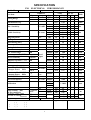
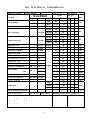
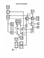
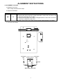
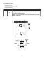
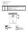
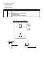
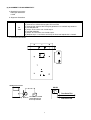
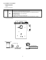
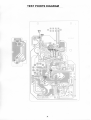
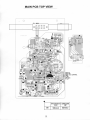
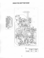
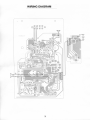
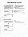
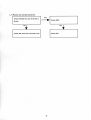
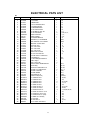
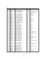
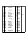
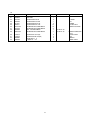
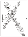
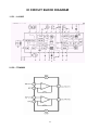
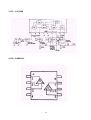
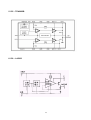
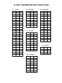
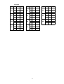
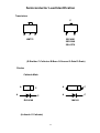
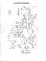
U2 AM/FM-STEREO 2 BANDS RADIO RECEIVER CONTENTS Specification ………………………………………………………………………………………………………2-3 Block Diagram ………………………………………………………………….………………………..……………..4 Alignment Instructions…………………………………………………………………….……….………….…...2-10 Test Points diagram………….……………………………………………………………….……….………….…...11 Main PCB Top View…………………………………………………………………………….……….……………12 Main PCB Bottom View.………………………………………………………………………….……..………..…..13 Wiring Diagram..….………………………………………….………………….….……………..……………14 Troubleshooting Flow Chart..….………………………………………….……………….….……………..……15-16 Electrical Parts List………………………………………………………………………………....……………17-19 Mechanical Parts List……………………………………………………………………….………….………….20-21 Exploded Views.…………………………………………………………………………….…………….……………22 IC Circuit Block Diagram…………………………………………..…………….………………………………23-25 IC and Transistor Voltage Chart….……………………………..…………………………….…………………26-27 Semiconductor Lead Identifications……………………………………………………………………..……..…28 Schematic Diagram………………………………………….………………………………………………………..29 1 SPECIFICATION FM. Model: U2 ELECTRICAL Brand: SANGEAN/ROBERTS Temp: Condition Input Output Test Item PERFORMANCE 25 Tuning Range R. H. : 75 % freq Min Max Intermediate freq. Max. Sensitivity S/N=6dB Usable Sensitivity S/N=30dB Image Rejection 127.4MHz R.O. I.F. Rejection 10.7MHz S/N=6dB 3db Limiting(1mV) Min. output Tuning Ind. Sens. Current consumption AFC action range Stereo separation (1KHz) headphone Stereo sensitivity headphone 60dB 60dB 60dB Rated output Spurious rejection103.35MHz 60dB S/N Ratio Am. suppression 60dB Mod 75kHz **Output Power 1kHz Speaker 4 DIN Audio 60dB Mod 22.5kHz **Output Power 1kHz T.H.D. (75KHz dev.) Load 32 RL:4 10% THD VOL MAX. Calibration Audio Fidelity –3dB (W/Pre-emphasis) De-emphasis 50uSec Bass booster action 1KHz VOLUME AT CENTER POSITION 80Hz 30Hz Supply Voltage: DC 6V emark: ( ) ( ) ( ) ( ) ( ) R. O. :50 mW Test No. 1 2 3 Unit MHz MHz dB dB dB 90MHz 60 50 98MHz 18 24 98MHz 98MHz 98MHz 98MHz 98MHz 3 18 150 500 28 5 24 180 200 22 28 98MHz 60 50 dB 98MHz 98MHz 98MHz 46 36 2.0 8+8 40 30 1.8 5+5 dB 98MHz 10% THD *Lowest Batt. volt. LED OFFĺ ON 60dB Value Nom. Lim. 87 +-0.2 108.5 +-0.3 10.7 +-0.1 12 18 12 18 12 18 18 24 18 24 18 24 32 26 dB dB mv dB mA kHz 22 dB dB dB W mW 98MHz 1mV Over load capacity 90 98 106 90 98 106 106 Date: 2003/9/9 98MHz 90M 98M 106M R.O LOW HIGH Load: 4 Ohm mW 1 2 >106 2 dB +-1000 KHz 4.0 4.2 35 75 15k 12k 3 +14 3 -6 Modulation: Dev.22.5kHz V Approved ( ) ( ) ( ) % by Hz dB @1kHz Released/Tested by MW Model: U2(ATR-1) ELECTRICAL PERFORMANCE Temp: 25 Brand: COMMON R. H. : 75 Condition Test Item Input Output Value Test No. Lim. Min. 515 +-7 Max. 1730 +-20 455 +-3 600 kHz 48 52 S/N=6dB 1000 kHz 46 50 1400kHz 46 50 600 kHz 52 58 1000 kHz 50 56 1400kHz 50 56 1000kHz 36 30 dB S/N=20dB 1 2 3 Unit Nom. Intermediate freq. Usable Sensitivity Date: 2003/9/9 Freq. Tuning Range Max. Sensitivity % kHz kHz dB dB Image Rejection S/N=6dB I. F. Rejection (450KHz) Selectivity( 10KHz) S/N=6dB 60 50 dB S/N=6dB 32 26 dB 7 +-3 KHz R.O 2 4 % R.O 4 4.2 V Bandwidth(-6dB) T. H. D. ( 5mV ) *Lowest Batt. Volt. LED OFFĺ Tuning Ind. Sens. 56 S/N Ratio (RF 5mV) Current Consumption 74dB /m 74dB /m Audio fidelity (-6dB) 1000kHz R.O **Output power Mod 80% 74dB /m 10%THD Over Load Capacity 80% Mod 10%THD A. G. C. F. O. M. 100 dB dB 170 mA <100 Hz >2.5 KHz 2 1.8 W 100 >90 140 600 +-50 1000 +-80 1400 +-60 Load: 4 Ohm ) ( ) ( ) ( ) ( ) ( ) ( ) ( ) KHz 3 % Modulation: Dev.30% @1kHz Approved by /m dB <15 Remark: ( dB >50 Whistle Modulation(5mV/M) R. O. : 50 mW /m 32 /m Calibration Supply Voltage: DC 6 V dB Released/Tested by BLOCK DIAGRAM 4 ALIGNMENT INSTRUCTIONS (1) ALIGNMENT FOR AM IF a. Required Instruments AM IF Sweep Generator with Scope b. Alignment Procedure Mode Adjustment AM T4 Procedure (1) Turn on the radio. (2) Connect the input of the AM IF sweep generation in series with a resister of 1.2K Ohm to the test point TP2 and TP7. (3) Connect the RF output of the AM IF sweep generation in series with a resister of 2.2K ohm to another test point TP3. (4) Adjust T4 to have a max. output and best center marker frequency to 455kHz. c. Instrument Connection T4 Test Point 455KHz Marker Test Point TP3 TP2 103pF IN RF OUT 1.2Kȍ 2.2Kȍ AM IF Sweep Generator 5 (2) ALIGNMENT FOR FM IF a. Required Instruments FM IF Sweep Generator with Scope b. Alignment Procedure Mode Adjustment FM T1 T3 Procedure (1) Turn on the radio. (2) Connect the input of the FM IF sweep generation in series with a resister of 1.2k Ohm to the test point TP4 and TP7. (3) Connect the RF output of the FM IF sweep generation in series with a resister of 2.2k ohm to another test point TP5. (4) Adjust T3 make curve with respect to the Center marker frequency of 10.7MHz. (5) Adjust T1 have a max. c. Instrument Connection T1 T3 Test Point 10.7MHz Marker Test Point TP5 TP4 103pF 103pF RF OUT IN 1.2Kȍ 2.2Kȍ FM IF Sweep Generator 6 (3) ALIGNMENT FOR FM SENSITIVITY a. Required Instruments FM Signal Generator SSVM b. Alignment Procedure Mode Adjustment L2 TC2 Procedure (1) Set the power switch to ON. (2) Connect a SSVM to the test point TP8 and TP9. (3) Connect the output of the FM signal generator to the test point TP5 and TP7. (4) Set FM 90 MHz. (5) Adjust L2 to have a max. Audio output. (6) Set FM 106 MHz. (7) Adjust TC2 to have a max. Audio output. (8) Repeat steps 4-7 until best sensitivity on these two frequencies is formed. c. Instrument Connection L2 TC2 AM Signal Generator SSVM Test Point TP5 Test Point TP8 103pF Test Point TP9 TP7 7 (4) ALIGNMENT FOR FM RANGE a. Required Instruments FM Signal Generator SSVM b. Alignment Procedure Mode Adjustment L3 TC3 Procedure (1) Set the power switch to ON. (2) Connect a SSVM to the test point TP8 and TP9. (3) Connect the output of the FM signal generator to the test point TP5 and TP7. (4) Set FM 87 MHz. (5) Adjust L3 to have a max. Audio output. (6) Set FM 108.5 MHz. (7) Adjust TC3 to have a max. Audio output. (8) Repeat steps 4-7 until best sensitivity on these two frequencies is formed. c. Instrument Connection TC3 L3 AM Signal Generator SSVM Test Point TP5 Test Point TP8 103pF Test Point TP9 TP7 8 (5) ALIGNMENT FOR AM SENSITIVITY a. Required Instruments AM Signal Generator SSVM b. Alignment Procedure Mode Adjustment T2 TC4 Procedure (1) Set the power switch to ON. (2) Connect a SSVM to the test point TP8 and TP9. (3) Connect the output of the FM signal generator to a standard loop antenna. (4) Set AM 600 kHz. (5) Adjust T2 to have a max. Audio output. (6) Set AM 1400 kHz. (7) Adjust TC4 to have a max. Audio output. (8) Repeat steps 4-7 until best sensitivity on these two frequencies is formed. c. Instrument Connection T2 TC4 AM Signal Generator SSVM 60 cm Test Point TP8 The radio is located Loop Antenna perpendicularly to the Loop Antenna Test Point TP9 9 (6) ALIGNMENT FOR AM RANGE a. Required Instruments AM Signal Generator SSVM b. Alignment Procedure Mode Adjustment T5 TC1 Procedure (1) Set the power switch to ON. (2) Connect a SSVM to the test point TP8 and TP9. (3) Connect the output of the FM signal generator to a standard loop antenna. (4) Set AM 515 kHz. (5) Adjust T5 to have a max. Audio output. (6) Set AM 1750 kHz. (7) Adjust TC1 to have a max. Audio output. (8) Repeat steps 4-7 until best sensitivity on these two frequencies is formed. c. Instrument Connection T5 TC1 AM Signal Generator SSVM 60 cm Test Point TP8 The radio is located Loop Antenna perpendicularly to the Loop Antenna Test Point TP9 10 '.'%64+%#.2#65.+5T 7 4GH01 2CTV0Q &GUETKRVKQP 3V[ 6 6 6 6 6 6 6 6 6 6 6 6 6 6 +%.# +%.#0 +%0,/. +%76%6&#Ä&+2 +%.#&+25 +%6'#$Ä2&+2 %*645##4 %*64*/516Ä %*645%4 &+1&'0Ä6 &+1&'0 %*&+1&'// .'&4'& M *4&9 .'&14046Ä;.&9 $#4#06%1+. #&,%1+. #&,%1+. #&,%1+. #&,%1+. (+:'&%1+.O*, 52%1+.Z6Z 28%9(Ä.6Ä#5 4Ä84-$Z 5(Ä84-$ #6&2Ä1 2%$Ä##64Ä 52- : 9 54ÄÄ($Ä&0 ,#%-*2 ( ,#%-&%Ä#)2$6. (+.6'4.6/5#Ä# (+.6'4.6*9 (+.6'4)(/$ %06$#5'Z2Ä* 9#55; 2 './8Z './8Z './8Z './8Z './8Z './8Z. './8Z './8:. './8:Ä './8Z './8Z './8Z 25,8 /;,8Ä6 %*%%%8021Ä% 17 4GOCTM +% +% +% +% +% +% 3 3 3Ä & & & .'& .'& 6 6 6 6 . . . 84 84 59 ,- ,- %( 5(4 %( %10 %10 % % % % % % %Ä % % % % % % % % 7 4GH01 2CTV0Q 6 6 &GUETKRVKQP 3V[ %*%%%8021Ä% %*%%-8:4Ä% %*%%-8:4Ä% %*%%<8;8Ä% %*%%<8(Ä% %*%%-8:4Ä% %*%%-8:4Ä% %*%%,8021Ä% %*%%,8021Ä% %*%%,8021Ä% %*%%-8:4Ä% %*%%,8021Ä% %*%%<8;8Ä% %*%%,8021Ä% %*%%-8:4Ä% 4&9,Ä6 4&9,Ä6 %*4&9,Ä% %*4&9,Ä% %*4&9,Ä% %*4&9,Ä% %*4&9,Ä% %*4&9,Ä% %*4&9,Ä% %*4&9,Ä% %*4&9-,Ä% %*4&9-,Ä% %*4&9-,Ä% %*4&9-,Ä% %*4&9-,Ä% %*4&9-,Ä% %*4&9-,Ä% %*4&9-,Ä% %*4&9-,Ä% %*4&9-,Ä% %*4&9-,Ä% %*4&9-,Ä% %*4&9-,Ä% %*4&9-,Ä% %*4&9-,Ä% %*4&91,Ä% %*,7/21,Ä$ %*4&9,Ä# %*4&91,Ä# 9,7/2 OO 9,7/2 OO 9,7/2 OO 18 4GOCTM % % %Ä %Ä % % % % % % % % % % % 4 4 4 4 4 4 4 4 4 4 4 4 4 4 4 4 4 4 4 4 4 4 4 4 4 4 ,2 4 ,2 ,2 ,2 ,2Ä 7 4GH01 2CTV0Q . &GUETKRVKQP 928% $.- 928% $.- 928% 4'& 9 49 9 4$ 95*+'.& 19 3V[ 4GOCTM 52Ä 52 ,9 52 #06 /'%*#0+%#.2#46S.+56 7 4GH01 2#4601 , , , , $ & , , , , , , , , , , , , , , , , , , , , , , , , ,# ,# , ,#Ä , ,# ,#Ä ,#Ä ,# ,#Ä ,# ,# ,# ,# ,# ,# ,# &'5%4+26+10 .#/2)7+&' &47/5*#(6 '2&%+0*1.&'4 .'&*1.&'4 416#4;-01$4+0) $#66'4;2.#6' 52'#-'4*1.&'4 670+0)84#55; 41*1.&'4 41B'4/+0#. $#66'4;5%4'9*1.&'4 *'#65+0- *#0&.'575Ä2.#6' 416#4;-01$4+0) %.+%-524+0) 624(+:Ä9#5*'4 2%$$4#%-'6 +05'46/076 $#66'4;524+0) Ä $#66'4;524+0) Ä *'/'.105*''6 '8#52#%'4 :/ %#$+0'62#%-+0) $#66'4;%18'42#%-+0) 52'#-'42#%-+0) 52-%18'42#%-+0) 41>#%-+0) $#0&2#%-+0) 52-5%4'92#%-+0) 81.7/'2#%-+0) 52-%18'4%#$2#%-+0) (4106%#$+0'6 $#%-%18'4 $#66'4;%18'4 %18'4(+:2.#6' (41062#0'.2.#6' *#0&.'$#4 *#0&.'*1.&'4 4 *#0&.'*1.&'4 . 670+0)-01$ 21+06'4-01$ $#0&-01$ 81.7/'-01$ (4106%#$+0'6%75*+10 $#%-%18'4%75*+10 '2&%+0%75*+10 (4#/'/'6#. 52'#-'4)4+.. 20 36; &9)01 #Ä#64Ä #Ä#64Ä #Ä#64Ä .'&Ä# #ÄÄ #Ä#64Ä #Ä#64Ä #Ä#64Ä #Ä#64Ä #Ä#64Ä #Ä#64Ä #Ä#64Ä #Ä#64Ä #Ä#64Ä #Ä#64Ä #Ä#64Ä #Ä#64Ä #Ä#64Ä #Ä#64Ä #Ä#64Ä# #Ä#64Ä #Ä#64Ä# #Ä#64Ä #Ä#64Ä# #Ä#64Ä #Ä#64Ä #Ä#64Ä #Ä#64Ä #Ä#64Ä #Ä#64Ä #Ä#64Ä #Ä#64Ä #Ä#64Ä #Ä#64Ä #Ä#64Ä #Ä#64Ä #Ä#64Ä #Ä#64Ä #Ä#64Ä #Ä#64Ä #Ä#64Ä #Ä#64Ä 4'/#4- (14$#%-%#$ 7 4GH01 2#4601 &'5%4+26+10 36; &9)01 4'/#4- 2+Ä-01$ 28% 670+0) 52-Z(/Z *#0&.'Z52-Z *#0&.'Z$#%-Z '2Z 2%$Z%#$Z 2%$ *#0&.' &47/5*#(6 ,#Ä ,# # # 52'#-'42#0'. 41 5%4'9,/2Z0+ 5%4'9,/2Z0+ 5%4'9,/(Z<- 5%4'9,/2Z<- +0*':#)105%4'9/Z +0*':#)105%4'9/Z $#6%18'4(+:$#4 +0*':#)105%4'9/Z #Ä#64Ä #Ä#64Ä #Ä#64Ä 5%4'9262Z 0+ 5%4'92629Z 0+ 56''.$#.. %4+0)F 21 41 44 5 52 5 31 42 43 14 29 48 57 48 57 57 57 45 49 56 37 27 56 30 27 30 54 56 56 27 27 30 33 30 55 32 50 32 55 55 55 1 55 32 1 8 55 32 63 26 55 12 53 22 55 4 4 2 7 17 23 61 22 24 60 59 56 62 21 61 10 11 15 40 13 15 62 28 9 51 34 EXPLODED VIEW 38 3 60 60 62 13 15 47 15 62 19 39 6 59 20 59 56 7 55 55 26 55 25 32 55 36 32 35 16 23 11 32 32 30 50 58 27 30 16 16 56 27 59 56 59 30 27 30 46 16 27 56 49 56 16 59 59 IC CIRCUIT BLOCK DIAGRAM 1. IC1 – LA1805 2. IC2 – TDA2822 23 3. IC3 – LA1186N 4. IC4 – NJM2100L 24 5. IC5 – TEA2025B 6. IC6 – LA5003 25 IC AND TRANSISTOR VOLTAGE CHART IC1 – LA1805 IC2 – TDA2822 IC5 – TEA2025B PIN FM AM PIN FM AM PIN FM AM 1 1.5 1.5 1 0 0 1 0 0 2 1.5 1.5 2 0 0 2 2.8 2.8 3 3 3 3 0 0 3 0 0 4 0.3 0.6 4 0 0 4 0 0 5 1.5 1.5 5 0 0 5 0 0 6 0 0 6 0 0 6 0.6 0.6 7 0.5 0.3 7 0 0 7 0 0 8 1 0.3 8 0 0 8 5.6 5.6 9 1.5 1.5 9 0 0 10 1.5 1.5 10 0 0 11 2.4 3 11 0.6 0.6 12 0.5 0.5 PIN FM AM 12 0 0 13 0 0 1 0.9 0 13 0 0 14 1.4 1.4 2 1.6 0 14 5.5 5.5 15 0.5 0.9 3 2.9 0 15 2.8 2.8 16 1.5 1.4 4 0 0 16 5.6 5.6 17 1.5 1.5 5 0 0 18 1.5 1.5 6 2.7 0 19 0.3 0.3 7 1.5 1.6 20 3 3 8 2.0 0 PIN FM AM 21 3 3 9 2.7 0 1 3 3 22 1.5 1.5 2 0 0 23 1.5 1.5 3 5 5 24 1.5 1.5 IC3 – LA1186N IC4 – NJM2100L PIN FM AM 1 1.5 1.5 2 1.5 1.5 3 1.6 1.6 4 0 0 5 1.6 1.6 6 1.6 1.6 7 1.5 1.5 8 3 3 26 IC6 – LA5003 Transistor Q2 Q3 Q4 Q5 FM AM FM AM FM AM C 3 3 C 0 0 C 0 0 B 0.3 0.3 B 0.6 0.6 B 0 0 E 0 0 E 0 0 E 0 0 G 0 0 C 1.6 1.6 C 5.7 5.7 D 0 0 B 2.2 2.2 B 5 5 S 0 0 E 1.6 1.6 E 5.7 5.7 C 0 0.9 C 3 3 C 0 0.3 B 0.6 0 B 1.5 1.5 B 0.6 0 E 0 0 E 1.6 1.6 E 0 0 C 3 3 C 0 0 B 1.4 1.4 B 3 3 E 0.8 0.8 E 3 3 Q6 Q7 Q8 Q9 27 Q10 Q11 Q12 Semiconductor Lead Identification Transistors C B C B E E 2SC4081 2SD1048 2SA1576 HM772 (E:Emitter C:Collector B:Base S:Source G:Gate D:Drain) Diodes Cathode Mark A C A C A C A C 1N4148 RLS4148 (A:Anode C:Cathode) 28