1
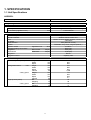
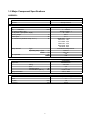
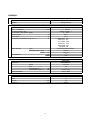
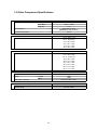
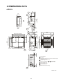
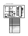
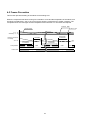
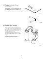
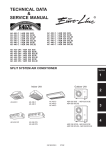
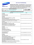
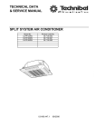
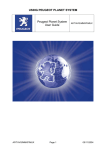
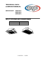
TECHNICAL DATA
& SERVICE MANUAL
INDOOR UNIT:
ASR525CL
ASR536CL
ASR548CL
SPLIT SYSTEM AIR CONDITIONER
Model No.
ASR525CL
ASR536CL
ASR548CL
Product Code No.
387006100
387006101
387006102
0.8180.365.0
10/2004
• Ground the unit following local electrical codes.
• The Yellow/Green wire cannot be used for any connection
different from the ground connection.
• Connect all wiring tightly. Loose wiring may cause overheating
at connection points and a possible fire hazard.
• Do not allow wiring to touch the refrigerant tubing, compressor,
or any moving parts of the fan.
• Do not use multi-core cable when wiring the power supply and
control lines. Use separate cables for each type of line.
IMPORTANT!
Please read before installation
This air conditioning system meets strict safety and operating
standards.
For the installer or service person, it is important to install or
service the system so that it operates safely and efficiently.
For safe installation and trouble-free operation, you must:
• Carefully read this instruction booklet before beginning.
• Follow each installation or repair step exactly as shown.
• Observe all local, state and national electrical codes.
• Pay close attention to all warning and caution notices given in
this manual.
•The unit must be supplied with a dedicated electrical line.
When transporting
Be careful when picking up and moving the indoor and outdoor
units. Get a partner to help, and bend your knees when lifting to
reduce strain on your back. Sharp edges or thin aluminium fins on
the air conditioner can cut your fingers.
WARNING
When installing...
This symbol refers to a hazard or unsafe practice which can result
in severe personal injury or death.
… In a ceiling
Make sure the ceiling is strong enough to hold the unit-weight.
It may be necessary to build a strong wooden or metal frame to
provide added support.
… In a room
CAUTION
Properly insulate any tubing run inside a room to prevent
"sweating", which can cause dripping and water damage to
walls and floors.
This symbol refers to a hazard or unsafe practice which can result
in personal injury or product or property damage.
... In moist or uneven locations
Use a raised concrete base to provide a solid level foundation
for the outdoor unit. This prevents damage and abnormal
vibrations.
If necessary, get help
These instructions are all you need for most installation sites and
maintenance conditions.
If you require help for a special problem, contact our sale/service
outlet or your certified dealer for additional instructions.
... In area with strong winds
Securely anchor the outdoor unit down with bolts and a metal
frame. Provide a suitable air baffle.
In case of improper installation
The manufacturer shall in no way be responsible for improper
installation or maintenance service, including failure to follow the
instructions in this document.
... In a snowy area (for heat pump-type systems)
Install the outdoor unit on a raised platform that is higher then
drifting snow. Provide snow vents.
SPECIAL PRECAUTIONS
When connecting refrigerant tubing
• During installation, connect before the refrigerant system and
then the wiring one; proceed in the reverse orden when removing
the units.
• Keep all tubing runs as short as possible.
• Use the flare method for connecting tubing.
• Apply refrigerant lubricant to the matching surfaces of the flare
and union tubes before connecting them; screw by hand and
then tighten the nut with a torque wrench for a leak-free
connection.
• Check carefully for leaks before starting the test run.
WARNING
When wiring
ELECTRICAL SHOCK CAN CAUSE SEVERE
PERSONAL INJURY OR DEATH. ONLY QUALIFIED,
EXPERIENCED ELECTRICIANS SHOULD ATTEMPT
TO WIRE THIS SYSTEM.
NOTE:
Depending on the system type, liquid and gas lines may be either
narrow or wide. Therefore, to avoid confusion, the refrigerant
tubing for your particular model is specified as narrow tube for
liquid, wide tube for gas.
• Do not supply power to the unit until all wiring and tubing are
completed or reconnected and checked, to ensure the grounding.
• Highly dangerous electrical voltages are used in this system.
Carefully refer to the wiring diagram and these instructions when
wiring.
Improper connections and inadequate grounding can cause
accidental injury and death.
When servicing
• Turn the power OFF at the main power board before opening
the unit to check or repair electrical parts and wiring.
• Keep your fingers and clothing away from any moving parts.
• Clean up the site after the work, remembering to check that no
metal scraps or bits of wiring have been left inside the unit being
serviced.
• Ventilate the room during the installation or testing the refrigeration
system; make sure that, after the installation, no gas leaks are
present, because this could produce toxic gas and dangerous
if in contact with flames or heat-sources.
2
Table of Contents
Page
4
4
7
10
1. SPECIFICATIONS
1-1 Unit specifications
1-2 Major Component specifications
1-3 Other Component specifications
2. DIMENSIONAL DATA
11
3. ELECTRICAL DATA
13
13
14
3-1 Electric Wiring Diagram
3-1 Schematic Diagram
15
15
16
4. FUNCTION
4-1 Room Temperature Control
4-2 Freeze Prevention
5. TROUBLESHOOTING
17
6. CHECKING ELECTRICAL COMPONENTS
29
29
30
30
31
6-1 Measurement of Insulation Resistance
6-2 Checking Continuity of Fuse on PCB Ass'y
6-3 Checking Motor Capacitor
6-4 Thermistor Characteristic Curve
3
1. SPECIFICATIONS
1-1 Unit Specifications
ASR525CL
Power source
220 - 240V ~ 50Hz
Voltage rating
230V
Performance
Capacity
Air circulation (High/Med./Low)
Features
Controls/Temperature controls
Remote Controller
Timer
Fan speed
Airflow direction
Air Filter
Operation sound
Refrigerant tubing connections
Refrigerant
tube diameter
Refrigerant
Refrigerant control
Dimensions & Weight
Dimensions (include panel)
Package dimensions
Unit
Ceiling panel
Weight (include panel)
Ceiling panel
m³/h
High/Med./Low
Narrow tube
Wide tube
dB-A
mm(in.)
mm(in.)
Height
Width
Depth
Height
Width
Depth
Volume
Height
Width
Depth
Volume
Net
Shipping
Net
Shipping
mm
mm
mm
mm
mm
mm
m3
mm
mm
mm
m3
kg
kg
kg
kg
4
Cooling
See catalogue with the requested matching
1140/1020/840
Microprocessor/ I.C. thermostat
Wireless remote control unit
ON/OFF 24 hours & Daily program, 1-hour OFF
3 and Auto
Auto (Remote control)
Washable, easy acces, long life (2500 hr.)
37/35/31
Flare type
6,35 (1/4)
15,88 (5/8)
R407C
Capillary tube
338
860
860
320
880
840
0,238
110
965
965
0,1
22
26
6
8
DATA SUBJECT TO CHANGE WITHOUT NOTICE
ASR536CL
Power source
220 - 240V ~ 50Hz
Voltage rating
230V
Performance
Capacity
Air circulation (High/Med./Low)
Features
Controls/Temperature controls
Remote Controller
Timer
Fan speed
Airflow direction
Air Filter
Operation sound
Refrigerant tubing connections
Refrigerant
tube diameter
Refrigerant
Refrigerant control
Dimensions & Weight
Dimensions (include panel)
Package dimensions
Unit
Ceiling panel
Weight (include panel)
Ceiling panel
m³/h
High/Med./Low
Narrow tube
Wide tube
dB-A
mm(in.)
mm(in.)
Height
Width
Depth
Height
Width
Depth
Volume
Height
Width
Depth
Volume
Net
Shipping
Net
Shipping
mm
mm
mm
mm
mm
mm
m3
mm
mm
mm
m3
kg
kg
kg
kg
5
Cooling
See catalogue with the requested matching
1920/1680/1320
Microprocessor/ I.C. thermostat
Wireless remote control unit
ON/OFF 24 hours & Daily program, 1-hour OFF
3 and Auto
Auto (Remote control)
Washable, easy acces, long life (2500 hr.)
42/39/35
Flare type
9,52 (3/8)
19,05 (3/4)
R407C
Capillary tube
368
1150
860
350
1170
840
0,35
110
1250
965
0,131
27
32
8
10
DATA SUBJECT TO CHANGE WITHOUT NOTICE
ASR548CL
Power source
220 - 240V ~ 50Hz
Voltage rating
230V
Performance
Capacity
Air circulation (High/Med./Low)
Features
Controls/Temperature controls
Remote Controller
Timer
Fan speed
Airflow direction
Air Filter
Operation sound
Refrigerant tubing connections
Refrigerant
tube diameter
Refrigerant
Refrigerant control
Dimensions & Weight
Dimensions (include panel)
Package dimensions
Unit
Ceiling panel
Weight (include panel)
Ceiling panel
m³/h
High/Med./Low
Narrow tube
Wide tube
dB-A
mm(in.)
mm(in.)
Height
Width
Depth
Height
Width
Depth
Volume
Height
Width
Depth
Volume
Net
Shipping
Net
Shipping
mm
mm
mm
mm
mm
mm
m3
mm
mm
mm
m3
kg
kg
kg
kg
6
Cooling
See catalogue with the requested matching
1920/1680/1320
Microprocessor/ I.C. thermostat
Wireless remote control unit
ON/OFF 24 hours & Daily program, 1-hour OFF
3 and Auto
Auto (Remote control)
Washable, easy acces, long life (2500 hr.)
42/39/35
Flare type
9,52 (3/8)
19,05 (3/4)
R407C
Capillary tube
368
1150
860
350
1170
840
0,35
110
1250
965
0,131
27
32
8
10
DATA SUBJECT TO CHANGE WITHOUT NOTICE
1-2 Major Component Specifications
ASR525CL
Controller PCB
Part No.
Controls
CR-XR254GS
Microprocessor
Fan & Fan Motor
Type
Q'ty ……. Diameter
Fan motor model…Q'ty
No. Of poles…rpm (230 V, High)
Running Amps
Power input
Coil resistance (Ambient temp. 20 °C )
Safety devices
mm
A
W
Ω
Type
Operating temp. Open
Close
°C
°C
µF
VAC
Run capacitor
Panel
Model
Flap motor
rating
rpm
nominal output
coil resistance (25°C)
W
kΩ
Dew proof heater
Heat Exch. Coil
Coil
Rows
Fin pitch
face area
Centrifugal fan
1…. Ø 443
SFG6X-41D6P…1
6 … 470
0,611
31,4
BRN-WHT: 170,3
WHT-VLT: 18,1
VLT-ORG: 43,2
ORG-YEL: 43,2
WHT-PNK: 83,5
YEL-BLK: 60,2
Internal thermal protector
130 ± 8
79 ± 15
4,5
440
ASG25SCE
M2LB24ZA12
240 VAC
2,5
3
15,62 ± 15%
240 V, 26W
Aluminium plate fin / Copper tube
2
1,5
mm
0,343
m2
DATA SUBJECT TO CHANGE WITHOUT NOTICE
7
ASR536CL
Controller PCB
Part No.
Controls
CR-XR254GS
Microprocessor
Fan & Fan Motor
Type
Q'ty ……. Diameter
Fan motor model…Q'ty
No. Of poles…rpm (230 V, High)
Running Amps
Power input
Coil resistance (Ambient temp. 20 °C )
Safety devices
mm
A
W
Ω
Type
Operating temp. Open
Close
°C
°C
µF
VAC
Run capacitor
Panel
Model
Flap motor
rating
rpm
nominal output
coil resistance (25°C)
W
kΩ
Dew proof heater
Heat Exch. Coil
Coil
Rows
Fin pitch
face area
Centrifugal fan
1…. Ø 443
SFG6X-81A6P…1
6 … 530
0,765
38
BRN-WHT: 75,1
WHT-VLT: 6,7
VLT-ORG: 20,6
ORG-YEL: 27,4
WHT-PNK: 42,7
YEL-BLK: 58
Internal thermal protector
130 ± 8
79 ± 15
5
440
ASG3648E
M2LB24ZA12
240 VAC
2,5
3
15,62 ± 15%
240 V, 26W
Aluminium plate fin / Copper tube
2
1,5
mm
0,556
m2
DATA SUBJECT TO CHANGE WITHOUT NOTICE
8
ASR548CL
Controller PCB
Part No.
Controls
CR-XR254GS
Microprocessor
Fan & Fan Motor
Type
Q'ty ……. Diameter
Fan motor model…Q'ty
No. Of poles…rpm (230 V, High)
Running Amps
Power input
Coil resistance (Ambient temp. 20 °C )
Safety devices
mm
A
W
Ω
Type
Operating temp. Open
Close
°C
°C
µF
VAC
Run capacitor
Panel
Model
Flap motor
rating
rpm
nominal output
coil resistance (25°C)
W
kΩ
Dew proof heater
Heat Exch. Coil
Coil
Rows
Fin pitch
face area
Centrifugal fan
1…. Ø 443
SFG6X-81A6P…1
6 … 530
0,871
51,9
BRN-WHT: 75,1
WHT-VLT: 6,7
VLT-ORG: 20,6
ORG-YEL: 27,4
WHT-PNK: 42,7
YEL-BLK: 58
Internal thermal protector
130 ± 8
79 ± 15
6
440
ASG3648E
M2LB24ZA12
240 VAC
2,5
3
15,62 ± 15%
240 V, 26W
Aluminium plate fin / Copper tube
2
1,5
mm
0,556
m2
DATA SUBJECT TO CHANGE WITHOUT NOTICE
9
1-3 Other Component Specifications
Trasformer
Rating
Primary
Secondary
Capacity
Ω
Coil resistance
Thermal cut-off temp.
Thermistor ( Coil sensor )
Resistance
ΚΩ
Thermistor ( Room sensor TH1)
Resistance
Drain pump
Model
Rating
ΚΩ
ATR-II215TA
VAC 230V, 50Hz
10,6V - 0.93A
7 VA
(WHT-WHT): 96,5
(BRN-BRN): 0,8 (at 20°C)
150°C
PBC-41E-S14
-10 °C 23,7 ± 5%
-5 °C 18,8 ± 5%
0 °C 15,0 ± 5%
5 °C 12,1 ± 5%
10 °C 9,7 ± 5%
15 °C 8,0 ± 5%
KTEC-35-S6
0 °C 16,5 ± 5%
5 °C 12,8 ± 5%
10 °C 10,0 ± 5%
20 °C 6,3 ± 5%
30 °C 4,0 ± 5%
40 °C 2,7 ± 5%
45 °C 2,2 ± 5%
50 °C 1,8 ± 5%
55 °C 1,5 ± 5%
PJV-1434A
230V
12W
500 mm / 400 cc/min.
Voltage
Input
Total head / capacity
Safety float switch
Model
Contact rating
FS-0218-102
DC 5V - 50W
10
2. DIMENSIONAL DATA
ASR525CL
5
261
221
292
232
X-view
100
339
7
124
59
124
6
157
48
30
2
12
25
860
500
12
100
776
368
7
124
9
12
2
221
225
12
776
Air intake grille
Air outlet
Refrigerant liquid line [D. 9.52 (In case of 25 type,
use the tube connector.)]
Refrigerant gas line
D. 12.7: 9, 12 type
Drain connection
Power supply entry
For discharge duct
For fresh air intake
9 Suspension bolt mounting
8
Panel center
377
X
820 (Ceiling opening)
566 (Suspention bolt pitch)
860
500
124
1
4
820 (Ceiling opening)
757 (Suspention bolt pitch)
308
3
182
Units: mm
11
ASR536CL
ASR548CL
124
291
232
59
6
292
X-view
100
339
7
5
244
157
124
182
30
338
2
12
25
790
2
8
12
1066
1150
513
9
124
8
249
12
12
180
12
244
776
Panel center
522
500
3
757 (Suspention bolt pitch)
X
1110 (Ceiling opening)
856 (Suspention bolt pitch)
860
48
820 (Ceiling opening)
1
4
124
Air intake grille
Air outlet
Refrigerant liquid line (D.9.52)
Refrigerant gas line (D.19.05)
Drain connection
Power supply entry
For discharge duct
For fresh air intake
9 Suspension bolt mounting
3. ELECTRICAL DATA
3-1 Electric Wiring Diagram
DPH
IND LAMP
ASSY
LM
7
YEL
WHT
GRY
BLK
SWITCH
ASSY
1 2 3
1
1 2
1 2
1 2 3
2P (RED)
COIL
2P (YEL)
ROOM
3P (WHT)
SW ASSY
7
7P (WHT)
W/LESS
CONNECTOR
4P(WHT)
GRY
BLK
YEL
WHT
BRN
RED
ORG
S 1 2 3 4
P 1 2 3 4
BLK
BLK
BLK
BLK
TH1 (COIL)
TH2 (ROOM)
1
1 3
1 3
3P (RED)
DPH
3P (GRN)
LM
CONTROLLER (CR-XR254GS)
PRY
2P (WHT)
SEC
2P (WHT)
DP
3P (BLU)
1 3 5
1 2
1 2
1 3
FS
FM 7P (WHT)
3P (RED) COM M H L
1 3
3P (WHT)
49FMI
1 3 5 7
1 3
BRN
E
SUP
5P (WHT)
4
TERMINAL PLATE(4P)
TO OUTDOOR UNIT
POWER SUPPLY
P
DP
S
TR
FS
1 2 3 4 5 6 7 8 9
1 2 3 4 5 6 7 8 9
GRN/YEL
GRN/YEL
P
S
3
PNK
PNK
BRN
BRN
BLK
ORG
YEL
VLT
ORG
WHT
VLT
WHT
GRY
GRY
GRY
GRY
CONNECTOR
9P(WHT)
BLK
BLK
BLK
BLK
BRN
BRN
2
WHT
WHT
WHT
1
BRN
RED
GRN/YEL
RC
FMI
GRN/YEL
EARTH
TERMINAL
EARTH
TERMINAL
13
EARTH
TERMINAL
3-2 Schematic Diagram
CR-XR254GS
CONTROLLER
4P-2
2
1
1
RY06
RY04
3
TR
RY01
H
3
2
RY02
RY03
RY08
RY05
3
3
M
5
1
1
7
7
1
2
3
1
2 SW
3
IND
RY02
L
3
RY03
7
FS
1
RY04
2
4
6
5
3
4
RY05
DPH
LM
DP
9
3
8
1
TH1
1
FMI
4P-4
RY06
2
49FMI
5
2
RY01
1
1
3
TH2
RC
1
2
1
1
1
COIL
RY08
1
4P-1
1
F01 (3.15A)
SYMBOLS
DESCRIPTION
FMI
INDOOR FAN MOTOR
49FMI
INDOOR MOTOR THERMAL PROTECTOR
RC
RUNNING CAPACITOR
F01
FUSE
DP
DRAIN PUMP
DPH
DEW PROOF HEATER
LM
AUTO LOUVER MOTOR
TR
POWER TRANSFORMER
RY01-RY06,
RY08
AUXILIARY RELAY
FS
FLOAT SWITCH
TH1
THERMISTOR (INDOOR COIL)
TH2
ROOM THERMISTOR
CR-X254GS
INDOOR CONTROLLER
IND
INDICATOR LAMP ASSY
SW
SWITCH ASSY
TERMINAL PLATE
CONNECTOR
TERMINAL
14
ROOM
4. FUNCTIONS
4-1 Room temperature control
Room temperature control is obtained by cycling the compressor ON and OFF under control of the room
temperature sensor in the remote control unit.
The room temperature (and other information) is transmitted every 5 minutes by the remote control unit to the
controller in the indoor unit.
Signal from remote control unit
5 minutes
set temp.
5 minutes
5 minutes
5 minutes
5 minutes
5 minutes
5 minutes
Thermo.
OFF
Thermo.
ON
Thermo.
OFF
Thermo.
ON
Thermo.
ON
Thermo.
ON
Thermo.
OFF
T+1 °C
T °C
More than
5 minutes
Compressor
ON
OFF
5 minutes
3 minutes
ON
OFF
3 seconds
Outdoor fan
Indoor fan
ON
OFF
Room temp.
ON
OFF
3 seconds
ON
OFF
ON
OFF
Set speed
The control circuit will not attempt to turn the compressor ON until the compressor has been OFF for at least
3 minutes. To protect the compressor from stalling out when trying to start against the high side refrigerant
pressure, the control circuit has a built-in automatic time delay to allow the internal pressure to equalize.
As a protective measure, the control circuit switches the compressor OFF not before than 5 minutes
of compressor operation.
Thermo. ON :
When the room temperature is above T + 1°C (T°C is set temperature).
Compressor
ON
Thermo. OFF :
When the room temperature is equal to or below set temperature T°C.
Compressor
OFF
15
4-2 Freeze Prevention
This function prevents freezing of the indoor heat exchange coil.
When the compressor has been running for 6 minutes or more and the temperature of the indoor heat
exchange coil falls below –0.8°C, the control circuit stops the compressor for at least 3 minutes. The
compressor does not start again until the temperature rises above 8°C or 6 minutes has elapsed.
Thermo. OFF
Thermo. ON
Room temp.
T+1 ° C
Set temp. T ° C
Indoor heat exch.
coil temp.
More than
6 minutes
6 minutes
–0.8 ° C
More than
6 minutes
Compressor
Indoor fan
ON
More than
6 minutes
OFF
ON
ON
Set speed
OFF
Set speed
16
ON
5. TROUBLESHOOTING
(1) Check before and after troubleshooting
Many problems may occur because of wiring or power supply problems, and so you should check these areas
first. Problems here can cause incorrect results in some of the other tests, and so they should be remedied
first.
1. Check power supply wiring
(a) Single-phase
Check that the power supply wires are correctly connected to terminal No. 1 through No. 4 on the
4P terminal plate on the indoor unit and L and N on the 6P terminal on the outdoor unit.
(b) 3-phase
Check that the power supply wires are correctly connected to terminal No.1 through No. 4 on the
4P terminal plate on the indoor unit and L1 through L3 and N on the 8P terminal on the outdoor
unit.
2. Check the inter-unit wiring
Check that the inter-unit control wires (AC 220 - 240 V Line voltage) are correctly connected
between the indoor unit and outdoor unit.
Single-phase outdoor unit
Indoor Unit
3-phase outdoor unit
Outdoor Unit
Indoor Unit
Outdoor Unit
B
B
1
1
1
1
2
2
2
2
Ground
4
Ground
4
Inter-Unit
Wiring
(Line voltage)
L
N
A
4
Power supply
L
4
Inter-Unit
Wiring
(Line voltage)
N
L1
A
Power supply
L1
L2
L2
L3
L3
N
N
Ground
0611_X_S
Ground
3. Check the power supply
Check that the voltage is within the specified range ( ±10% of the rating).
Check that power is supplied.
WARNING
If the following troubleshooting must be done with the power being supplied, take care not to touch
any uninsulated live parts that will given an ELECTRIC SHOCK.
4. Check the lead wires and connectors in indoor and outdoor units.
Check that the sheaths of the lead wires are not damaged.
Check that the lead wires are firmly connected to the terminal plate.
Check that the wiring has been performed correctly.
5. Reference
• Condition of general cooling operation (Thermo. ON)
SWEEP..................ON
Indoor fan speed....HIGH
17
(2) Air conditioner does not operate
1. Circuit breaker trips (or fuse blows).
(a) When the circuit breaker is set to ON, it trips immedialely.
• There is a possibility of ground fault.
• Check insulation resistance.
If the resistance value is 1M½ or less, insulation is defective.
(Example)
Earth
Remove power supply cords
from terminal plate in outdoor
unit.
• Check insulation resistance
of power supply cords.
+
Earth
*Set the circuit breaker to OFF.
1
+ +
Interunit
power line
3
+
L1
L2
L3
N
2
Outdoor
Indoor
unit
unit
4
5
1
1
Circuit
6
breaker
7
2
2
4
8
4
Power
3
3
Interunit
supply
power line
cords
+ +
+ +
4
1
Indoor
unit
1
2
3
4
+ + + +
3
+
Power
supply
cords
2
+ +
Circuit
breaker
Outdoor
unit
5
1
6
2
3
4
+
L
N
+ +
1
NO
Rewire
OK
2
Remove inter-unit power line
from terminal plate in outdoor
unit.
• Check insulation resistance
of outdoor unit.
NO
Insulation of
outdoor unit
is defective.
• Check insulation
resistance of
electrical parts
in outdoor unit.
Insulation of
indoor unit
is defective.
• Check insulation
resistance of
electrical parts
in indoor unit.
OK
3
Remove inter-unit power line
from terminal plate in indoor
unit.
• Check insulation resistance
of indoor unit.
NO
OK
Inter-unit power lines is
defective.
Rewire
18
(b) Circuit breaker trips in several minutes after turning the air conditioner on.
• There is a possibility of short circuit.
• Check capacity of circuit
breaker.
Replace it with a
suitable one.
(= larger capacity)
NO
Is capacity of circuit
breaker sufficient ?
• Check resistance of
outdoor fan motor winding.
• Check resistance of
compressor motor winding.
• Check resistance of louver
motor winding.
2
A.
Neither indoor unit nor outdoor unit runs.
No power is supplied
• Check power supply.
Is power being supplied
to outdoor unit ?
B.
Circuit breaker
is tripped.
Reset the breaker.
Power failure.
Wait for power to
be restored or
consult power
supply company.
NO
Check remote control unit.
• Try to run both indoor and
outdoor units with another
remote control unit.
OK
Other remote control
unit is defective.
19
C.
Check “Operation selector” switch in the indoor unit.
• Has “Operation selector”
switch been set to ON
position ?
IND. LAMP Ass’y or P.C.B.
Ass’y in the indoor unit
is defective.
YES
NO
Set “Operation selector”
switch to ON.
Neither unit runs.
Switch Ass’y or P.C.B.
Ass’y in the indoor unit
is defective.
D.
Check compressor motor protectors.
a)
High pressure switch (63PH)
Disconnect the socket from the 2P (WHT) connector.
Check the continuity between the No.1 and No.2 poles
of the socket.
• Check high pressure switch.
Is high pressure switch
actuated ?
(63PH)
YES
• Is outdoor heat exchanger
coil dirty or are there
obstruction near air suction
inlet of outdoor unit ?
Clean heat exchanger coil
or remove obstructions.
YES
NO
• Check if outdoor fan rotates.
Refer to “Only outdoor fan
does not run.”
b)
Compressor motor overcurrent relay
• Check compressor motor
overcurrent relay. (51C)
Is it actuated ?
NO
Refer to “CHECKING ELECTRICAL COMPONENTS
(Electro magnetic contactor)”.
YES
Consult power supply company
and restore voltage to
normal value.
• Check power supply voltage. YES
Is voltage 90% of rated
voltage or less?
NO 90% of rated
voltage or more.
• Following causes may be considered.
Locked rotor of compressor.
Overcharged refrigerant.
Insufficient air for outdoor unit ventilation.
Obstruction in front of outdoor unit.
20
E.
Check the auxiliary relay. (1Y or 2Y)
• Check coil resistance of
auxiliary relay.
(1Y or 2Y)
F.
Check the indoor fan motor thermal protector (49FMI)
• Disconnect the socket from the 9P (WHT) connector.
• Check the continuity
between No. 8 and No.9
poles of the 9P socket.
No continuity.
Thermal protector (49FMI)
is actuated.
• Check fan rotation.
Rotate the fan gently once
or twice by hand.
Fan cannot
be rotated.
OK
• Check fan motor capacitor.
G.
Check fan casing
for foreign matter
on inside.
Remove foreign
matter or repair.
Fan motor burnout
or foreign matter
in bearing.
Repair or replace.
Check the fuse on the P.C.B. Ass’y in the indoor unit.
• Check fuse on P.C.B.
Ass'y in indoor unit for
continuity.
• Check resistance of louver
motor winding.
(LM)
OK
When the fuse blows.
• Check transformer. (TR)
OK
• Check resistance of indoor
fan motor winding.
(FMI)
• Check coil of compressor
motor magnetic contactor.
(52C)
OK
• P.C.B. Ass'y is defective.
OK
21
(3)
Outdoor unit does not run.
A.
Check the COOL/FAN selector switch in the remote control unit.
• Is COOL/FAN selector switch NO
set to COOL ?
B.
Set to COOL.
Check the set temperature.
Try to lower set
temperature using temperature
setting button “COOLER”.
YES
• Set “Operation selector”
switch to TEST in indoor
unit.
Outdoor unit runs.
Is room temperature too
low ?
NO
• Try to run both indoor and
outdoor units with another
remote control unit.
OK
Other remote control unit is
defective.
(Room sensor in remote
control unit is defective.)
C.
Outdoor unit is abnormal.
a)
Check the power supply wiring
• Check negative phase relay.
(47C)
Is it actuated ?
NO
Rewire power supply cords.
22
b)
Check the compressor motor thermal protector (49C)
• Check compressor motor
thermal protector. (49C)
Is temperature of compressor
abnormally high ?
YES
Insufficient refrigerant gas.
NO
Compressor is defective.
• Check compressor motor
magnetic contactor.
(52C)
(Only the outdoor fan does not run.)
D.
Check the indoor unit P.C.B.
• Check P.C.B. Ass’y.
• Check voltage between
terminals No.2 and No.4 on
terminal plate.
No voltage appears.
P.C.B. Ass’y is defective.
23
Charge refrigerant gas.
(4)
Indoor unit does not run.
The indoor fan and louver motor do not run.
P.C.B. Ass’y is defective.
(5)
Some parts fail to operate.
(1) Only indoor fan does not run.
• Check fan rotation.
Rotate fan gently once or
twice by hand.
Fan cannot
be rotated.
• Check resistance of fan
motor winding.
OK
• Check fan motor capacitor.
OK
P.C.B assy is defective.
(2) Only louver motor does not run.
• Check resistance of
louver motor winding.
OK
P.C.B. Ass’y or remote
control unit is defective.
24
Check fan casing
for foreign matter
on inside.
Remove foreign
matter or repair.
Fan motor burnout
or foreign matter
in bearing.
Repair or replace.
(6)
Outdoor fan does not run.
• Check fan rotation.
Rotate fan gently once or
twice by hand.
Fan cannot
be rotated.
• Check fan casing
for foreign matter
on the inside.
Remove foreign
matter or repair.
• Fan motor burnout
or foreign matter
in bearing.
Repair or replace.
• Check resistance of fan
motor winding.
OK
• Check fan motor capacitor
• Check continuity between
terminals on compressor
motor magnetic contactor.
(7)
Outdoor fan speed is not switched from High to Low even when the outdoor
temperature falls below 25.5°C.
• Check thermostat (23S).
• Check coil resistance of
auxiliary relay.
(1Y)
(8)
Compressor does not run.
• Check compressor motor capacitor.
OK
• Check resistance of compressor motor winding.
OK
• Check compressor motor overload relay.
OK
• Check continuity between terminals R-U, and
then S-V on the magnetic contactor.
25
NG
Replace magnetic
contactor.
(9)
Poor cooling
Check position of remote
control unit.
• Does cool air from air conditioner reach remote control
unit directly ?
• Is wide tube between indoor unit
and outdoor unit insulated ?
Change position of
remote control unit.
YES
Insulate wide tube and
then execute taping with
narrow tube.
NO
YES
• Measure temperatures of suction
and discharge air of indoor unit.
Temperature
difference
Possibility of
is small.
insufficient
refrigerant.
Charge
refrigerant
Temperature difference between
suction and discharge air is
large enough (approx. 10 deg. or more).
• Check clogging of air
filter.
• Is fan speed set to LOW ?
Air filter is clogged.
Set fan speed to either
HIGH or MEDIUM.
YES
• Review cooling load estimate,
if performance of air conditioner
is normal.
(10)
Clean filter.
Reduce cooling load or
replace the unit with
higher cooling capacity.
Excessive cooling.
• Set temperature is too low.
• Is remote control unit placed
where it can detect room
temperature properly ?
Set temperature to
higher value using
temperature setting
button of remote
control unit.
YES
NO
Change position of
remote control unit.
26
(11) PCB for "SCL" models
1 2 3
S002
LED1
LED2
POW
1
S001
D005
S002 (Capacity Code)
25 type
36 type
48 type
1
OFF
ON
ON
2
OFF
OFF
ON
3
OFF
OFF
OFF
Meaning of LED indication
POW
Light
Light
LED1
Off
Flash
LED2
Off
Light
D005
Light
Light
Light
Light
Off
Off
Light
Light
Light
Off
Cause of trouble
Normal state
High pressure switch is activated,
Outdoor fan thermal protector activated,
Outdoor coil thermistor is open or short
Low pressure switch is activated
Negative phase, Defective phase
27
(12) Defective Sensor.
1. Indoor (heat exchanger) coil temp. Sensor is defective.
(a) Open (=No continuity in sensor)
Compressor and outdoor fan repeatedly go ON for 10 minutes and OFF for 6 minutes when sensor opens.
(b) Short
“Freeze Prevention” does not operate when dehumidified water is frozen on the indoor coil.
2. Room temp. Sensor (in the remote control unit) is defective.
(a) Open (=No continuity in sensor)
Neither the outdoor fan nor compressor runs.
(b) Short
The outdoor fan and compressor do not stop. — Excessive cooling.
28
6. CHECKING ELECTRICAL COMPONENTS
6-1 Measurement of Insulation
Resistance
power plug
(Local supply)
Ground
The insulation is in good condition if the
resistance exceeds 1MΩ
probe
Insulation
tester
NOTE
6-1-1. Power supply wires
The shape of the power plug may differ from that
of the air conditioner which you are servicing.
Clamp the grounding terminal of the power plug
with a lead clip of the insulation resistance tester
and measure the resistance by placing a probe
on both the two power terminals. (fig.1)
Fig. 1
Terminal plate
Then, also measure the resistance between the
grounding and other power terminals. (fig.1)
Probe
6-1-2. Indoor Unit
Clamp a metallic part of the unit with the lead
clip of the insulation resistance tester and measure
the resistance by placing a probe on each terminal
screw where power supply lines are connected on the
terminal plate. (fig.2)
Clip
Copper
tube or
metallic part
Insulation
tester
Fig. 2
6-1-3. Outdoor Unit
Clamp an aluminium plate fin or copper tube with
the lead clip of the insulation resistance tester
and measure the resistance by placing a probe
on each terminal screw on the terminal plate. (fig.2)
Note that the ground line terminal should be skipped
for the check.
Probe
Clip
Copper
tube or
metallic part
6-1-4. Measurement of Insulation
Insulation
tester
Resistance for Electrical Parts
Disconnect the lead wires of the desired electric
part from terminal plate, capacitor, etc.
Similary disconnect the connector.
Then measure the insulation resistance. (fig.3 and 4)
From fan motor,
compressor and
other parts
Metallic
part
NOTE: Refer to electric wiring diagram
Fig. 3
Probe
Clip
If the probe cannot enter the poles because the
hole is too narrow then use a probe with a
thinner pin.
Insulation
tester
Fig. 4
29
6-2 Checking Continuity of Fuse
on PCB Ass'y
Fuse
Remove the PCB Ass'y from the electrical component
box. Then pull out the fuse from the PCB Ass'y. (fig.5)
PCB Ass’y
Check for continuity using a multimeter as shown in fig.6
Fig. 5
Fuse
Fig. 6
6-3 Checking Motor Capacitor
Remove the lead wires from the capacitor terminals,
and then place a probe on the capacitor terminals as
shown in fig.7. Observe the deflection of the pointer,
setting the resistance measuring range of the
multimeter to the maximum value.
Multimeter
The capacitor is "good" if the pointer bounces to a
great extent and then gradually returns to its original
position.
The range of deflection and deflection time differ
according to the capacity of the capacitor.
Compressor motor
capacitor
Fan motor
capacitor
Fig. 7
30
6-4 Thermistor Characteristic Curve
1
1
Room temp. sensor
(KTEC-35)
Coil sensor
(PBC-41E)
40
35
10
30
Resistance (kn )
Resistance (kn )
9
8
7
6
5
4
25
20
15
10
3
5
2
0
–20
1
–15
–10
–5
0
5
Temperature (°C)
10
15
20
25
30
35
40
Temperature (°C)
31
10
15
20
Via Varese, 90 - 21013 Gallarate - Va - Italy
Tel. +39 0331 755111 - Fax +39 0331 776240
www.argoclima.it