1
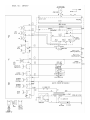
Fast Track Troubleshooting Model: SMH9207ST/XAA IMPORTANT SAFETY NOTICE – “For Technicians Only” This service data sheet is intended for use by persons having electrical, electronic, and mechanical experience and knowledge at a level generally considered acceptable in the appliance repair trade. Any attempt to repair a major appliance may result in personal injury and property damage. The manufacturer or seller cannot be responsible, nor assume any liability for injury or damage of any kind arising from the use of this data sheet. SUPPORT INFORMATION Training — Plus One http://my.plus1solutions.net/clientPortals/samsung/ Help — GSPN http://service.samsungportal.com/ Samsung 'Microwave' Diagnostic Code Quick Guide Failure Code Publication # tsSMH9207 Creation Date 2/28/2012 Cause E-11 Open E-12 Short E-13 T1 Max Time Error E-14 Dry Up / No Load Error Code Gas Sensor Error Case (E-1X) E-21 Open E-22 Short E-23 T1 Max Time Error (Preheating not completed) E-24 Over temperature error E-25 Abnormal temperature is sensed at Micro Cook E-26 Temp is not over the fixed AD in first 3 minutes after heater starts. Error Code Temp Sensor Error Case (E-2X) E-31 Open (When value of HEX is above “FF” for 5 seconds) E-32 Short E-33 The initial value of HEX is under “14” for 30 seconds while a weight sensor in operation. E-34 The initial value of K calculated by a weight sensor is above and under “±28” as value of HEX. E-35 The value of A is “-” as a weight sensor calculates. E-36 In case the door opens during sensor cooking. Error Code Gas Sensor Error Case (E-1X) E-41 Open E-42 Short E-43 T1 Max Time Error E-44 Dry Up E-45 Cooling Error (3minutes) E-46 Primary Open Error(3minutes) E-47 The door opens during cooking Error Code Easy/PH Sensor Error Case (E4) E-51 Open (Sense Failure) E-53 Read/Write Error E-54 Zero not to be set Error Code EEPROM Error Case (E-5X) E-61 Open E-62 Short E-63 T1 Max Time Error Error Code Humidity Sensor Case (E-6X) -SE- Key Short Error (10 seconds) E-01 Door opens when the door should not be opened. E-02 Cooking Time Setting Over Error (MWO) E-03 Cooking Time Setting Over Error (Grill) E-04 Cooking Time Setting Over Error (Convection) E-05 Cooking Time Setting Over Error (Combination) E-06 It fails to sense that the swing heater has stopped for 20 seconds during cooking. E-08 In case function of MWO starts with spit inserted into cavity inside. E-09 The damper is not set to be positioned for 2 minutes. Error Code Others (E-0X, Letter) CN05 1) RY-POWER-L 2) RY-POWER-H 3) RY-INRUSH 4) G S 5) RY-BRIG HT 6) KEY7-AD 7) RY-SPARE 8) VFD FILAM ENT1 9) RY-NIG HT 10) VFD FILAM ENT2 11) RY-VENT-H 12) RY-O PTIO N 13) RY-VENT-M 14) -34V 15) RY-V_DO O R 16) G ND 17) BUZZER 18) G ND 19) RY-VENT-L 20) + 5V 21) RY-TT 22) + 5V 23) INT 24) TCO -S 25) RY-M AIN 26) STB CN03 Gas Sensor 4-3 5vdc Main PCB CN04 Door Connector 1 Door sw 3 Door sw 3-5 12vdc 4-5 5vdc RY02 In Rush Relay RY04 Power Low Relay RY06 Night Relay RY03 Power High Relay CN06 1-3 5vdc RY01 Main Relay RY08 TT RY09 Vent Low CN02 Pwr & Relay 1-(CN01-1) Vent High 3-(CN01-1) Vent Mid 5-(CN01-1) Vent Low 7-(CN01-1) TT 9-(CN01-1) Main Relay Contact RY10 Vent Mid RY05 Bright Relay RY11 Vent High CN01 Relay, Lamp, SMPS 1 Line 1 3-1 RY202 In Rush Relay Neutral Contact 5-1 RY206 Bright Lamp Relay Neutral Contact 5-1 RY205 Night Lamp Relay Neutral Contact The fuse is located on the noise filter. 1. Disconnect power and remove grille and Assembly Control Box. 2. Replace the fuse. Door Interlock Ass’y 3. When 20A fuse blows out by the operation of interlock monitor switch failure, replace the primary interlock switch, secondary interlock switch, door sensing switch, interlock monitor switch and power relay. 4. When the above four switches operate properly, check if any other part such as the control circuit board, blower motor or high voltage transformer is defective. L1 L1 N N The SMH9207 presents with the symptom of the microwave oven being “DEAD”. There are no functions available and the oven is incapable of operating at this time. Testing has shown that this problem can manifest due to a failure of the ASSY PCB MAIN which is located in the microwave ovens Door Assy. To Troubleshoot this failure, you will need a DVM (Digital Voltage Meter) capable of reading both AC and DC voltages. Use the Images on page three for reference. Step 1: Check that AC voltage is available and present in the microwave oven. Check the input voltage at the Noise Filter PCB Assy. Check for ≈ 120VAC on both the input and output connectors of the PCB. If the Voltage is not Present, check the input wire harness, outlet for voltage. Also check that the circuit breaker of fuse supplying the outlet is not open. If voltage is present at the input of the Noise Filter board, but not present at the output, check the 20 A, 250VAC fuse on the Board. Replace the fuse or board as necessary. Note: The wiring diagram in the Service Manual for SMH9207 is incorrect. Page 2 cannot be used to locate connectors and pins due to the mislabeling of the connectors. Please use the provided picture on page 3 for correct connector and pin assignments. Step 2.: The configuration of this microwave oven differs with the traditional configurations of ovens by Samsung. The Logic and Control of the microwave oven has been split between 2 (two) boards where in previous models, all functions are contained on one board. Unfortunately both of the new boards are described a ASSY PCB MAIN. For the purposes of troubleshooting, we will refer to the 2 boards as follows: Relay Circuit Board Assy (ASSY PCB MAIN) - Large board located in ASSY Control BOX Control Circuit Board Assy (ASSY PCB MAIN) - Located in in the ASSY DOOR Check if AC voltage is present at the Relay Circuit Board assy. (MAIN). Measure for ≈120VAC between CN01—Pin 1 (B6) and the Neutral line out of the noise filter Board assy. (White wire). If the voltage is not present check the following: 1. MGT TCO and the Cavity TCO for open conditions. Remove power form the microwave oven. Using an ohmmeter, check for continuity from the noise filter L voltage output (Black wire) to CN01— pin 1. If open, check each TCO individually with an ohmmeter and replace as necessary. If the AC voltage is present at CN01-Pin1, check for the presence of the Main Relay Control Signal (RYMAIN) from the Control Circuit Board which is located in the Door Assy. 1. Using a DC Multi-meter, check for a signal voltage at connector CN05 on the MAIN PCB. Check Pin 25. The signal should read: ≈3.5 vdc with the door closed. ≈4.5 to 5 vdc with the door open. Use the metal ASSY Bracket for DC gnd. If the signal is not present, this indicates a failure of the Control Circuit Board.(Also called MAIN). A final check is to look for 5 vdc at CN05—pins 22 and 20. If the 5 vdc is not present, the Control Circuit PCB has failed. The 5 vdc is created on the relay bd., but is loaded down and won’t be present. Parts: Control Circuit Board Assy. Please order: DE92-02135A ASSY PCB MAIN Relay Circuit Board Assy. This Board is not available as a service part. Please order: DE94-02097A The board is part of this assembly. ASSY CONTROL BOX Microwave Cooking Wattage Test Fill a 1000ml plastic room temperature container with cool tap water, temperature of the water should be 55-65 degrees Stir water with a thermometer and record the water temperature, remove thermometer. Place the container in the center of the lowest shelf or center of the bottom of the microwave. For units less than 1550 watts, operate the oven on high for exactly 63 seconds. Using the thermometer, stir the water to check the temperature of the water. Subtract the starting temperature from the final temperature; this will be the temperature rise. Temp Rise Output Temp Rise Out- 5 194 23 891 6 232 24 930 7 271 25 969 8 310 26 1007 9 349 27 1046 10 387 28 1085 11 426 29 1124 12 464 30 1162 NOTE: Check line voltage under load, lower line voltage will lower the power output. 13 504 31 1201 14 542 32 1240 Procedure for measurement of microwave energy leakage 15 581 33 1279 16 620 34 1317 17 659 35 1356 18 697 36 1395 3. Set survey meter with dual ranges to 2,450MHz. 19 736 37 1434 4. When measuring the leakage, always use the 2 inch spacer cone with the probe. Hold the probe perpendicular to the cabinet door. Place the spacer cone of the probe on the door and/or cabinet door seam and move along the seam. The door viewing window and the exhaust openings moving the probe in a clockwise direction at a rate of 1 inch/sec. If the leakage testing of the cabinet door seam is taken near a corner of the door, keep the probe perpendicular to the areas making sure that the probe end at the base of the cone does not get closer than 5 cm to any metal. If if gets closer than 5 cm, erroneous readings may result. 20 775 38 1472 21 814 39 1511 22 852 40 1550 1. Pour 275±15cc of 20±5°C(68±9°F) water in a beaker which is graduated to 600cc, and place the beaker in the center of the oven 2. Start to operate the oven and measure the leakage by using a microwave energy survey meter. 5. Measured leakage must be less than 4mW/cm2 after repair and adjustment. Maximum allowable leakage is 5mW/cm2. 4mW/cm2 is used to allow for measurement and meter accuracy. Safety precautions Some semiconductor (“solid state”) devices are easily damaged by static electricity. Such components are called Electrostatically Sensitive Devices (ESDs). Examples include integrated circuits and field-effect transistors. Immediately before handling any semiconductor components or assemblies, drain the electrostatic charge from your body by touching a known earth ground. M/W Information M/W Power 1100 Watts M/W Weight 52.7 Lbs Primary 0.43Ω Secondary 120-125Ω Filament Vent Turbo Vent Normal 0.0Ω 30Ω 67Ω Vent High 59Ω TT & Stirrer Motors 120Ω Fan Motor 32-40Ω Specifications High Voltage Transformer Motors High Voltage Warning Do not attempt to measure any of the high voltages --this includes the filament voltage of the magnetron. High voltage is present during any cook cycle. Before touching any components or wiring, always unplug the oven and discharge the high voltage capacitor WARNING: It is critical to route wires and wire harness identical to the way they were, to prevent electromagnetic interference causing possible fault codes.