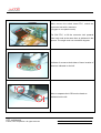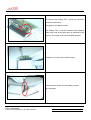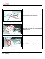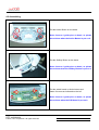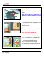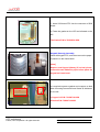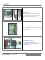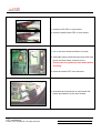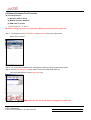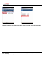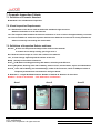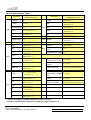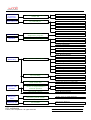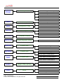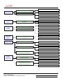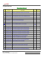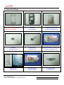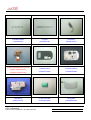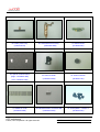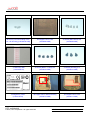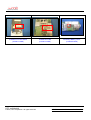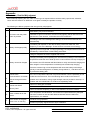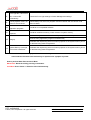
1
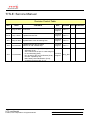
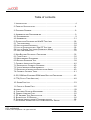
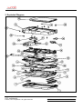
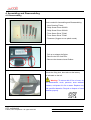
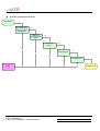
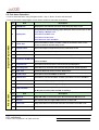
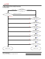
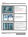
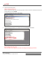
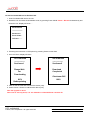
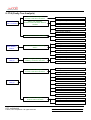
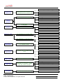
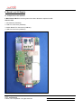
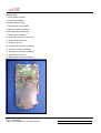
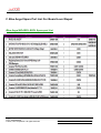
Service Manual for Blue Angel HTC Proprietary Confidential Treatment Requested Rev. A03 Jun 22, 2005 HTC Corp. Engineering Mobility HTC confidential © 2004, HTC Corporation. All rights reserved. TOTAL 71 CONT.ON. 2 PAGE NO. 1 TITLE: Service Manual Revision Control Table REV. DATE AX01 Aug,16 2004 First Draft Technical Support Felix Lu Sep,7 2004 Update Antenna Test Technical Support Felix Lu A01 Sep,16 2004 Update Board Level & Labeling Plan Technical Support Felix Lu A02 Jan,06 2005 Update Antenna Spec & Image address for SD Card Backup Technical Support Felix Lu A03 1. Repair notice for Keypad (Qwerty) assembly (P.23). 2. Set screw driver torque to 0.9±0.05kgf-cm for unit assembly (P.26) Technical Henry_Dal Jun,22 2005 3. Run In test for NFF unit verification.(P.29) Support 4. Unit SPL updated (P.54). 5. Main battery label identification (P.63). 6. Updated board level SPL (P.71). AX02 CONTENTS DEP. REVISED APP´D STGE.PER. HTC confidential © 2004, HTC Corporation. All rights reserved. TOTAL 71 CONT.ON. 3 PAGE NO. 2 Table of contents 1. INTRODUCTION ······························································································ 4 2. PRODUCT SPECIFICATION ··············································································· 4 3. EXPLODED DIAGRAM ······················································································ 8 4. ASSEMBLING AND DISASSEMBLING ·································································· 9 4.1 DISASSEMBLING ··························································································· 9 4.2 ASSEMBLING ····························································································· 21 5. DIAGNOSTICS PROGRAM AND WINCE TEST ITEM ·········································· 28 5.1 TOOLS REQUIRED······················································································· 28 5.2 HOW TO ENTER DIAGNOSTIC ······································································· 28 5.3 LIST OF DIAGNOSTICTEST / WIN CE TEST ITEM ··········································· 28 5.4 LIST OF RUN IN TEST ITEMS (DIAGNOSTIC MODE) ······································· 29 5.5 TEST ITEM OPERATION ··············································································· 30 6. MAIN BATTERY RE-CERTIFY PROCEDURE ······················································ 32 6.1 FLOW CHART····························································································· 32 6.2 MEASUREMENT PROCEDURE ······································································ 33 6.3 BATTERY RUNDOWN TEST ········································································ 38 7. COSMETIC INSPECTION CRITERIA ·································································· 40 7.1 DEFINITION OF COSMETIC STANDARD ·························································· 40 7.2 VISUAL INSPECTION REQUIREMENTS ··························································· 40 7.3 DEFINITON OF INSPECTION DEFECTS AND AREAS ········································· 40 7.4 COSMETIC CRITERIA TABLE ········································································ 41 8. OS, GSM AND EXTENDED ROM IMAGE REFLASH PROCEDURE ······················· 42 9. FTA (FAULTY TREE ANALYSIS) ····································································· 48 10. SPARE PART LIST ······················································································ 53 11. PHOTO OF SPARE PART ············································································· 55 APPENDIX …………………………………………………………………………..59 A. CUSTOMER, RETAILER MISJUDMENT ····························································· 59 B. GENERIC LABELING PLAN ············································································· 62 C. RF ANTENNA TEST SPECIFICATION ······························································· 64 D. BOARD LEVEL 2.5 REPAIRS ·········································································· 66 E. PROBLEM IDENTIFICATION & TROUBLESHOOTING ·········································· 68 F. BLUE ANGEL SPARE PART LIST FOR BOARD LEVEL REPAIR ··························· 71 HTC confidential © 2004, HTC Corporation. All rights reserved. TOTAL 71 CONT.ON. 4 PAGE NO. 3 1.Introduction This manual provides the technical information to support the service activities of Harrier. This document contains highly confidential information, so any or all of this document should not be revealed to any third party. 2.Product Specification Platform • Microsoft Pocket PC 2003 Phone Edition – English, Korean, Spanish, Traditional Chinese, Simplified Chinese, Italian, Portuguese, German • Dimensions: Main unit 18.7mm(T) x 69.8mm(W) x 125mm (H) • Weight (Main Unit) under 210g Processor • Low power, high performance 32-bit Intel PXA 263 CPU 400MHz (embedded 32MB NOR Flash) • IT Calypso + IOTA, GSM/GPRS solution Memory • Flash ROM: 32/64/96MB • Flash RAM: 64/128MB LCD Module • 3.5” Transflective TFT-LCD with back-light LEDs, 240 x 320 x 64K Colors • Sensitive touch screen GSM/GPRS functional block • GPRS/GSM (Tri-band) module • GSM900: 880-915, 925-960MHz, GSM1800: 1710-1785, 1805-1880MHz, GSM1900: 1850-1910, 1930-1990MHz • Internal antenna for tri-band GSM • Call holding, waiting, forwarding, barring, Calling Line Identity (CLI) • SMS (Short Message Service), MT, MO, SM reply, replace, acknowledgement, validity, 8 bit SMS data class 0/1 SMS • Display own number, telephone number storage capability w/Mute feature, Network selection, Cell broadcast • Explicit Call Transfer (ECT), Spool icon, Phase 2 Unstructured supplementary service data-MO/MT • WAV Ring tone download/compose, Long message (640 characters), Network Lock • AMR/EFR/FR/HR, EOTD, CPHS v4.2, PBCCH • GPRS class B, Multi-slot standard class 10 HTC confidential © 2004, HTC Corporation. All rights reserved. TOTAL 71 CONT.ON. 5 PAGE NO. 4 • 3V SIM operation, SIM Application Toolkit class 3, Release 00, Over the programming • Security: Ciphering A5.1 & A5.2, PIN1 & 2 control Stylus • Lock type mechanism Keyboard/button/switch • One power button (Wake-up key) • One voice recorder/voice command button (Wake-up key) • One volume control button (up and down) • One Camera capture button (Wake-up key) • One 5-way navigation button (Wake-up key) • Two phone buttons: SEND (Yes) & END (No) buttons (Wake-up keys) (with LED backlight) • RESET switch • Built-in 39 keys extractable QWERTY Keyboard (Wake-up key) (with LED backlight) • Key lock • 6 programmable AP buttons (1. Contacts 2. Calendar. 3. Start 4. Inbox 5. Menu 6. Done/OK) (Wake-up key) Notification • One bi-color LED (Green and Red) LED in the first lens for GSM standby, GSM message, GSM network status, PDA charging status, and PDA notification • Two respective (Blue and Green) LEDs in the same second lens for Bluetooth/WiFi status • Notification by Sound and Message on the display • Vibrator for notification Audio • Built-in Microphone, receiver and speaker • SW echo cancellation • Loudspeaker • SW echo cancellation, HW Full duplex • Receiver • 16-bits with 8KHz, 11KHz, 16KHz, 22KHz, 44.1KHz, 48KHz sampling rate [TBD] • WAV/WMA/MP3 stereo CMOS Camera • Color CMOS camera module • Resolution: VGA/QVGA/CIF/QQVGA • JPEG encoder • Fix Focus Function HTC confidential © 2004, HTC Corporation. All rights reserved. TOTAL 71 CONT.ON. 6 PAGE NO. 5 • Preview mirror on battery cover • Operation in 5 Lux (min.) • Video Light [TBD] Power • Battery ` Removable rechargeable Lithium Ion battery, 1400mAh (Typical) ` Separated backup battery (20mAh, rechargeable) ` Battery life: 15hrs of PDA only (without RF) [TBD] ` Talk time of 3~5 hours (at nominal RF Tx power level) ` Standby time: 200hrs ` Data Retention Time: 72hrs • AC Adapter ` AC input: 100 ~ 240 Vac, 50/60Hz ` AC input current: 0.2 Aac (max.) ` Output voltage: 5Vdc (typical) ` Output current: 2Adc (typical) Environment • Operating temp: 0 ~50 degree C. Humidity : 90% RH • Storage tem: -20 ~ 60 degree C. Humidity : 90% RH Peripheral Interface • Feature connector (22 pin)- Serial, USB Slave, power signals and Audio (support Car kit) • Infrared Port IrDA CIR (including remote control controller) • One Audio Jack (2.5ψ) • One R-UIM card slot • One SDIO/MMC card slot (B-Square SDIO driver) • One External antenna connector 802.11b Wireless LAN • Frequency Range: 2.4GHz to 2.4835GHz • Standards: IEEE 802.11b Direct Sequence Spread Spectrum compliant • Data Rates with Automatic Fallback:: 11Mbps_CCK, 5.5Mbps_CCK, 2Mbps_DQPSK, 1Mbps_DBPSK • Operation Channels: 1-11 for North America, 1-13 for Europe, 1-14 for Japan, 10-11 for Spain, 10-13 for France • Encryption: 64-, 128- bit WEP standard data encryption • Media Access Control: CSMA/CA with ACK • Network Architecture: Ad-Hoc Mode (Peer to Peer without Access point), Infrastructure Mode (Communications to wired HTC confidential © 2004, HTC Corporation. All rights reserved. TOTAL 71 CONT.ON. 7 PAGE NO. 6 networks via Access Points with Roaming) • Antenna: Internal antenna Bluetooth • Bluetooth 1.1 compliant • Class 2 transmit power-support voice and data transmission Accessories • Sync. Cable (USB/Serial) • Cradle (USB, Serial) • AC adapter • Car adapter • Stylus • AC adapter power plug • Car Kit (capable of muting car stereo when incoming call or call proceeding) • Stereo Wired headset-stereo earpiece with microphone • Mono Wired headset-mono earpiece with microphone • Mono Bluetooth headset-mono earphone with microphone • Optional Battery (1400mAh) • VGA/TV out kit (through USB interface, with AC input, remote control for presentation) • Remote kit with FM Radio Tuner • Remote Controller for VGA output • WiFi SD card • TTY Adapter Regulatory • NTSL, BQCF Certification, USB v1.1 Compliance test, JAVA TCK • R&TTE : EMC/SAR • CDG 1, 2, and 3 Applications • JAVA Virtue Machine (J2ME, CLDC, MIDP 2.0, JAM) • WAP 2.0 browser • MMS (with video clip support) • Camera Capture Utility (Resolution: VGA/QVGA/CIF/QQVGA) • Image Viewer/Album, Voice Recognition, Text to Speech, Photo ID, SIM Manager, SD Backup, Wireless Modem, Universal Remote Controller, Polyphonies MIDI ring tone, Instant Message HTC confidential © 2004, HTC Corporation. All rights reserved. TOTAL 71 CONT.ON. 8 PAGE NO. 7 3. Exploded Diagram HTC confidential © 2004, HTC Corporation. All rights reserved. TOTAL 71 CONT.ON. 9 PAGE NO. 8 4. Assembling and Disassembling 4.1 Disassembling Tools needed for Assembling and Disassembling. 1. Lens Cleaning Tissue. 2. Philip Screw Driver 000X50 3. Philip Screw Driver 000X40. 4. Torex Screw Driver T6X40 1 2 3 4 5 6 5. Torex Screw Driver T5X40 6. Tweezers.(Suggest to use plastic made) 3 1. Pull up to release the Stylus. 2. Remove the SD Card Filler. 2 1 3. Remove the Antenna Insert Rubber. Unlock the fixing lock, then take out the battery as indicated on the left. Warning: To reduce risk of fire or burns, do not disassemble, crush, puncture, short external contacts, or dispose of in fire or water. Replace only with specified batteries. Recycle or dispose of used batteries properly. HTC confidential © 2004, HTC Corporation. All rights reserved. TOTAL 71 CONT.ON. 10 PAGE NO. 9 There are 4 screws at the rear side of the unit. Note that there is 2 types of screws are used. 1 The P/N would be as follows: 1. 72H00642- 00M 2 2. 74H00441- 00M To open de case, remove 2 more screws surrounding the side of the unit as indicated on the left. Note that screw P/N is 72H00642- 00M. Once the 6 screws have been removed, Use fingers to open the housing. HTC confidential © 2004, HTC Corporation. All rights reserved. TOTAL 71 CONT.ON. 11 PAGE NO. 10 Use tweezers to tear down the tape on Keyboard FPC and connector as indicated on left. Next, remove the K/B FPC, unlock the connector lock with a tweezers. (Suggest to use plastic made) For K/B FPC, to lift the connector lock upwards from both ends at the same time as indicated in the picture. The angle must not exceed 90 degrees. If the microphone is defective, remove it from main board and then replace new one. Note: when disconnect the wire of Microphone and Vibrator. The angle must be within 20 degrees to mating axis. HTC confidential © 2004, HTC Corporation. All rights reserved. TOTAL 71 CONT.ON. 12 PAGE NO. 11 If the vibrator is defective, remove it from main board and then replace new one. Note: when disconnect the wire of Microphone, and Vibrator. The angle must be within 20 degrees to mating axis. Note: when disconnect the wire of Microphone, and Vibrator. The angle must be within 20 degrees to mating axis. There are 6 screws on main board. Firstly, to remove 4 screws to disassemble main board from bezel. Note that screw P/N is 72H00528-00M. HTC confidential © 2004, HTC Corporation. All rights reserved. TOTAL 71 CONT.ON. 13 PAGE NO. 12 Next, remove the camera FPC, unlock the connector lock with a tweezers. For Camera FPC, to lift the connector lock upwards from both ends at the same time as indicated in the picture. The angle must not exceed 90 degrees. Unfasten the 2 screws to disconnect the main board from Housing Frame as indicated on the left. Note that screw P/N is 72H00528-00M. Next, pull up the main board in 30 degrees to disconnect LCD FPC and Touch Panel FPC with tweezers. HTC confidential © 2004, HTC Corporation. All rights reserved. TOTAL 71 CONT.ON. 14 PAGE NO. 13 Take out the camera from camera holder as indicated on the left. Pull both sliding frames to the end as indicated on the left. Remove 4 screws on frame bezel to disassemble frame housing from bezel assembly. HTC confidential © 2004, HTC Corporation. All rights reserved. TOTAL 71 CONT.ON. 15 PAGE NO. 14 To disassemble bezel-assy & frame-assy. Use tweezers to pull out the frame spacers to Disassemble frame bezel & frame housing. Use tweezers to tear down the keypad from its right side as indicated on the left. Right side HTC confidential © 2004, HTC Corporation. All rights reserved. TOTAL 71 CONT.ON. 16 PAGE NO. 15 Next, to pull up the FPC to separate from bezel frame. KB FPC Use tweezers to tear down the tape on the upper right location. Unfasten 2 screws on the upper right location. HTC confidential © 2004, HTC Corporation. All rights reserved. TOTAL 71 CONT.ON. 17 PAGE NO. 16 If the speaker is defective, take out the speaker from the bezel and its wire from the hook, and then to replace new one. Note: when disconnect the wire of Speaker. The angle must be within 20 degrees to mating axis. Unfasten 2 screws on the upper left location and, then tear down the gasket on the FPC of switch board as indicated on the left. HTC confidential © 2004, HTC Corporation. All rights reserved. TOTAL 71 CONT.ON. 18 PAGE NO. 17 Next, remove the switch board FPC, unlock the connector lock with a tweezers. (Suggest to use plastic made) For S/W FPC, to lift the connector lock upwards from both ends at the same time as indicated in the picture. The angle must not exceed 90 degrees. Unfasten 2 screws at both sides of lower location of bezel as indicated on the left. Next, to separate the LCD from the bezel as indicated on the left. HTC confidential © 2004, HTC Corporation. All rights reserved. TOTAL 71 CONT.ON. 19 PAGE NO. 18 To remove the softkey FPC, unlock the connector lock with a tweezers. (Suggest to use plastic made) For softkey FPC, to lift the connector lock upwards from both ends at the same time as indicated in the picture. The angle must not exceed 90 degrees. Unfasten 2 screws on the switch board. Use tweezers to take out the softkey module pre-assembly. HTC confidential © 2004, HTC Corporation. All rights reserved. TOTAL 71 CONT.ON. 20 PAGE NO. 19 Use fingers to take out the switch board. Take out the Action button from the obverse side as indicated on the left. Use tweezers to take out the softkey button as indicated on the left. The Unit Disassembly is done already. HTC confidential © 2004, HTC Corporation. All rights reserved. TOTAL 71 CONT.ON. 21 PAGE NO. 20 4.2 Assembling Put the Action Button on the bezel. Note: there’re 4 guide pins on bezel, so please aim at them when the Action Button is put on it. Put the Softkey Button on the bezel. Note: there’re 4 guide pins on bezel, so please aim at them when the Softkey Button is put on it. Put the switch board on Action button and fasten 2 screws as indicated on the left. Note: there’re 4 guide pins on bezel, so please aim at them when the S/W board is put on it. HTC confidential © 2004, HTC Corporation. All rights reserved. TOTAL 71 CONT.ON. 22 PAGE NO. 21 Put the softkey FPC pre-assembly on the softkey button. Note: there’re 2 guide pins on softkey button, so please aim at them when the S/W board is put on it. (1)To assemble the LCD with bezel, and then insert softkey FPC into connector of S/W board as indicated on the left. 1 Note: if a new LCD needs to be replaced, please paste two copper foils before assembly. 2 1.The copper foil P/N: 72H00717-00M 2.The copper foil P/N: 72H00600-00M 1. Put on the S/W board FPC pre-assembly, and then fasten two screws on upper left side and two screws on bottom of right and left side. 2. Put on the speaker, and then plug in the connector and make its wire fix in the hook. 3. Fasten two screws on upper right side, and then paste the proof-tape as indicated on the left. HTC confidential © 2004, HTC Corporation. All rights reserved. TOTAL 71 CONT.ON. 23 PAGE NO. 22 1. Insert S/W board FPC into the connector of S/W Gasket board. 2. Paste the gasket on the LCD as indicated on the left. The Gasket P/N is 72H00539-00M. Keypad (Qwerty) Assembly Insert the keypad FPC, and then remove the paper to paste it on the frame bezel. [Note] Replace new Keypad (Qwerty) if it’s bad; please remove the twin adhesive paper before paste the keypad on frame bezel. It is required to paste a gasket and a copper on both 2 1 side of housing frame and bezel frame as indicated on the left. 1.Copper foil P/N: 72H00716-00M 2.Gasket P/N: 72H00714-00M HTC confidential © 2004, HTC Corporation. All rights reserved. TOTAL 71 CONT.ON. 24 PAGE NO. 23 Frame Assembly Insert frame housing into frame bezel, and then insert the two spacers on both sides to lock the frame assembly as indicated on the left. Insert the S/W board FPC into frame assembly, and then fasten 4 screws. Camera Module Assembly 1. Remove tape on camera holder. 2. Insert the camera into camera and fix it on camera holder. HTC confidential © 2004, HTC Corporation. All rights reserved. TOTAL 71 CONT.ON. 25 PAGE NO. 24 1 1. Insert the LCD FPC on main board. 2. Insert the switch board FPC on main board. 2 1. Put on the main board and fasten 2 screws. 2. Assemble antenna and camera module with main board, and then fasten 4 screws to fix it. Please paste the gasket on main board before assembly. 3. Insert the camera FPC into connector. 1. Assemble the microphone on main board and please pay attention on the wire location. HTC confidential © 2004, HTC Corporation. All rights reserved. TOTAL 71 CONT.ON. 26 PAGE NO. 25 Assemble the vibrator on main board and please pay attention on the wire location. The wire location is beneath main board as indicated on the left. Insert the keypad FPC into the side connector of main board, and then paste the soldering-proof tape on it as indicated on the left. 1. Assemble the housing, and then fasten 4 screws on rear back of unit and 2 screws on the side of unit. 2. Paste the warranty seal on the housing. 3. Insert the battery, and then push fixing lock. [Note]: 1. Set screw driver torque to 0.9±0.05kgf-cm. 2. Please set the volume button on the center before assembly. HTC confidential © 2004, HTC Corporation. All rights reserved. TOTAL 71 CONT.ON. 27 PAGE NO. 26 The Unit Assembly is done already. HTC confidential © 2004, HTC Corporation. All rights reserved. TOTAL 71 CONT.ON. 28 PAGE NO. 27 5. Diagnostic Program and Win CE test item 5.1 Tools required SD card with Diagnostic program loaded. 5.2 How to enter Diagnostic Program (1) Insert SD card with Diagnostic program loaded to the unit. (2) Press and hold Power + Record + Reset to enter diagnostic mode to perform the test. 5.3 List of Diagnostic / WinCE Test Items Win CE mode Diagnostic Program Mode No Item Description Remark 1 SDRAM Test Check SDRAM Size/Write/Read 2 Display Test Test the LCD display quality 3 Button Test Test the function of hot key 4 Keyboard Test Test the function of button on Keyboard 5 Touch Panel Test Touch screen alignment test. Suggest to test in WinCE 6 Checksum Test Verify the checksum of the ROM code for manufacturing 7 Brightness & LED Test Blight ON with in different brightness level and LED test 8 Playback Test Playback function test 9 Recording Test Recording function test 10 Timer Test Check the function of Real Time Clock 11 SD Card Test SD card Write/Read Test 12 Vibrator Test Test the function of the vibrator 13 Battery Test Check battery status 14 View Unit Info Check Unit S/N 15 Clear Talk Time No a. Clear call duration (Talk Time) b. M-system format (Clear all data in memory) Item Description 1 USB Test Suggest to test in Windows CE 2 SIR Test Suggest to test in Windows CE 3 Series Test Suggest to test in Windows CE 4 Wi-Fi Test Suggest to test in Windows CE Remark [Note]: Clear Talk Time 1. The test for the unit returns from field which needs to go through Refurbishment process. 2. This is process is very import to clear out the PIN-data in memory. HTC confidential © 2004, HTC Corporation. All rights reserved. TOTAL 71 CONT.ON. 29 PAGE NO. 28 5.4 List of Run In Test Items (for NFF unit verification) (1) For NFF unit verification, tie test condition for unit. (2) Insert SD card with Diagnostic program loaded to the unit. (3) Press and hold Power + Record + Reset to enter diagnostic mode to perform the test. (4) Select Run in test and press soft1 (2hour) for test time selection. Remark Timer Test Check the function of Real Time Clock 2 Vibrator Test Test the function of the vibrator 3 SDRAM Test Check SDRAM Size/Write/Read 4 Brightness & LED Test Blight ON with in different brightness level and LED test 5 Display Test Test the LCD display quality (R/G/Blue/W/Black pattern) 6 Playback Test Playback function test unit Description 1 Run-In Test Item Reliable test for CND No NFF definition: • Could not reproduce faulty symptom reported by end user. • Could not find any functional failure after functional test, RF test (if needed) and cosmetic check M/B NFF verification flow chart: Returned M/B Rework and upgrade NFF Appearance check for any customer abuse which may cause to reported failure NFF M/B Function Test NFF NG NG NG RF Calibration and Specs Test NG No Failure Found Repair HTC confidential © 2004, HTC Corporation. All rights reserved. TOTAL 71 CONT.ON. 30 PAGE NO. 29 Unit NFF verification flow chart: Returned unit Appearance check for any customer abuse which may cause to reported failure NFF Simulate EU conditions to reproduce reported failure NFF Run-in Test for 2 hrs NFF NG Full Function Test NG NFF NG RF (Antenna) Test NG NG Repair No Failure Found HTC confidential © 2004, HTC Corporation. All rights reserved. TOTAL 71 CONT.ON. 31 PAGE NO. 30 5.5 Test Items Operation (1) How to select test item: Using navigation button -"Up" or "Down" to select the test items (2) How to execute the test program: Press “Action” button to start each of test items. No 1 Item SDRAM Test Description Display Size and read/write test. It will show OK if pass. Stop on fail. Unit prompts for different display page to detect the defect of LCD, lines or dots. First display is Multiple Color, 2 Display Test Press Action to White Color Press Action to Dark Color Press Action to return Test Menu Win CE mode Diagnostic Program Mode 3 Button Test Press each button to know if it works. Follow the instruction shown on the screen to finish the test item. Stop on fail. 4 Keyboard Test Press each button on keyboard to test if it works. Stop on fail. 5 Touch Panel Test Tap the cross mark (+) with stylus on the correct location. Fail if no reaction. 6 Checksum Test Verifies the checksum of the code for manufacturing. 7 Brightness & LED Test Press “Action to test LED and brightness level of LCD (three stages), and then return Test Menu. 8 Playback Test Press Action to test the audio out from Internal speak/earphone. 9 Recording Test Press Action to record the sound and then play out from speak/ earphone. 10 Timer Test Check the Real Time Clock if it works. Stop on Fail. 11 SD Card Test Press Action to test Read/Write for SD card. 12 Vibrator Test Press Action, unit should vibrate, and then press Action to return Test Menu. 13 Battery Test Check the battery charging and capacity status. 14 View Unit Info Check the unit S/N for warranty period judgment. 15 Clear Talk Time No a. Clear call duration (Talk Time) b. M-system format (Clear all data in memory) Item Description 1 USB Test Plug USB cable to connect UUT to PC then and check if USB OK or not. 2 SIR Test Use a device that can support SIR function to connect UUT. 3 Series Test Plug serial cable to connect UUT to PC then and check if serial OK or not. 4 Wi-Fi Test Connect the UUT via wireless AP to surf Internet. HTC confidential © 2004, HTC Corporation. All rights reserved. TOTAL 71 CONT.ON. 32 PAGE NO. 31 6. Main Battery Re-certify Procedure 6.1 Flow Chart Under 3.75V Measure battery voltage ? Above 3.75V Charge to 3.75V above Charge ? Charge fail Fail Voltage check by Ds2760K ? OK Fail Currect check by Ds2760K ? OK Fail ACR check by Ds2760K ? OK Fail Parameter check by Ds2760K ? OK Fail Whole unit charge test OK Fail Whole unit discharge test ? OK Fail Run down test ? OK Battery is NG Battery is OK HTC confidential © 2004, HTC Corporation. All rights reserved. TOTAL 71 CONT.ON. 33 PAGE NO. 32 6.2 Measurement Procedure Tools requirement: A. Battery testing fixture B. Multi-meter with battery detecting plug C. Win2000 or above OS PC system D. Ds2760K battery testing program. Note: The Ds2760K program needs to installed onto PC in advance. Step 1: Main battery voltage check a. To detect battery voltage by multi-meter through battery connector. b. The battery voltage will appear on the multi-meter, make sure the voltage >= 3.75V Above ( keep connecting the battery, about 2 second later, the voltage will become “0”, it is normal situation) If the voltage < 3.75V please charge the main battery and then re-check the battery voltage must > 3.75V. HTC confidential © 2004, HTC Corporation. All rights reserved. TOTAL 71 CONT.ON. 34 PAGE NO. 33 Step 2: Parameter check by DS2760K test program Contact battery to detect battery parameter by DS2760K program HTC confidential © 2004, HTC Corporation. All rights reserved. TOTAL 71 CONT.ON. 35 PAGE NO. 34 The battery’s core parameter areas as follows: Voltage must > 3.75 V And = step 1 (+-0.15 V) It should have the value within + 3.125 ~ -3.125 mAmps If current is not between + 3.125~ -3.125 mAmps, Must to Click “Calibrate Offset “ button, , the value will be calibrated automatically. (it takes about 15 seconds) Purpose: make the current of sleep mode correct. Compare Voltage and ACR value Voltage must >= 3.75 V Accumulated charge must >= 300 mAhs If < 300mAhr, Must to Click “Set ACR “ button then re-fill out ACR value to be 300mAhrs HTC confidential © 2004, HTC Corporation. All rights reserved. TOTAL 71 CONT.ON. 36 PAGE NO. 35 Check address of 01h Must 01h = E7h Check address of 30h/31h/32h Must 30h = 47h 31h = 20h 32h = 95h Check address of 34h Must 34 = 00h Check address of Bh/3Ch/3Dh/3Eh/3Fh Must 3Bh = 23h 3Ch = 0Ah 3Dh = 14h 3Eh = 0Ah 3Fh = 00h HTC confidential © 2004, HTC Corporation. All rights reserved. TOTAL 71 CONT.ON. 37 PAGE NO. 36 Tools requirement: E. Battery testing fixture F. Multi-meter with battery detecting plug G. Win2000 or above OS PC system H. Ds2760K battery testing program. Note: The Ds2760K program needs to installed onto PC in advance. Step 1: Main battery voltage check c. To detect battery voltage by multi-meter through battery connector. HTC confidential © 2004, HTC Corporation. All rights reserved. TOTAL 71 CONT.ON. 38 PAGE NO. 37 6.3 Battery Rundown Test Procedure (A) Tool Requirement: (1) Windows 2000 or above (2) Battery Rundown Software (3) USB Cable or Cradle (4) ActiveSync3.7 or above (B) Please charge your unit to full capacity for battery (4 hours) before doing the test. Step 1: It is required to save powerdetect.exe and model.txt in the same folder under WinCE via ActiveSync. Step 2: It is unnecessary to adjust power management setting by using rundown test program. Step 3: Execute powerdetect.exe under WinCE, it will enter Sleep Mode after one Hour and generate a file named powercap.txt log. ÆRecord every two minutes & adjust the brightness to maximum. HTC confidential © 2004, HTC Corporation. All rights reserved. TOTAL 71 CONT.ON. 39 PAGE NO. 38 Powercap.txt Benchmark is 78% Step 4: Tap powercap.txt log to check if the rest battery capacity. If under 78%, please replace a new battery. HTC confidential © 2004, HTC Corporation. All rights reserved. TOTAL 71 CONT.ON. 40 PAGE NO. 39 7. Cosmetic Inspection Criteria 7.1. Definition of Cosmetic Standard B Standard is for refurbishment inspection. 7.2. Visual Inspection Requirements 7.2.1 Examination of the device shall be made with workbench light turned on. Ambient illumination is to be 500-1000 lux. 7.2.2 The inspector shall examine the device at a distance of 13 to 15 inches for approximately 7 seconds. 7.2.3 If a visual defect is noted, the inspector shall have an additional 10 seconds to closely examine the defect and classify it according the criteria table. 7.3. Definitions of Inspection Defects and Areas Scratch:A linear cut that penetrated beyond the surface of the material. A scratch can be felt by running your finger over it. Dot / Dent:A recessed spot or void in the surface of the material. Lint:A linear foreign object beyond the surface of the LCD. Bump:A hump in the surface of material. Area I:LCM, Bezel including phone key, APP button, action key and LED lens. Area II:Keyboard, Housing, back side of battery, antenna cover, release button, stylus and side buttons. Area III:Inner side of battery (not include battery), inside of SD connector, inside of USB port inside of Earphone jack and other area marked in the figure below. D: Diameter/ L: Length/ W: Width/ Number: Number of defects/ S: Distance of dot to dot Remark: 1. Crack is not allowed. 2. All dimensions in millimeters. Area I Area II Area III HTC confidential © 2004, HTC Corporation. All rights reserved. TOTAL 71 CONT.ON. 41 PAGE NO. 40 7.4. Cosmetic Criteria Table B standard Specs Item Bright dot** Dark dot** Red + Green + Blue ≦ 4 LCM* Dark dots ≦ 3 Area 3 Bump Lint Total number ≦ 5 Bur Particle Total number ≦ 5 Breakage on T/P None Spot Dent Area 1 Bump Bur Imprint mark Bright mark Spot Dent Area 2 Bump Bur Imprint mark Bright mark 2) Total number≦6 1) D < 0.7mm, S ≧ 10mm 2) Total number≦6 1) D < 0.7mm, S ≧ 10mm 2) Total number≦6 1) L ≦ 3mm, W≦0.254mm 2) No Hand Scrape 1) L ≦ 4mm, W≦0.3mm 2) Total number ≦ 3 1) L<2mm, W<0.2mm Scratch 2) Total number ≦ 4 Stylus 1) D < 0.5mm, S ≧ 15mm 2) Total number<3 Protruding over the top of None bezel Deformed/ Missing/ Loosen None 2) Total number ≦ 4 1) D < 0.5mm, S ≧ 15mm 2) Total number ≦ 4 1) L ≦ 3mm, W≦0.254mm Gap between touch panel 2) No Hand Scrape and bezel 1) 0.4≦ D ≦0.8 (mm) Gap between bezel and 2) Total number≦ 3 housing 1) L ≦ 2.5mm, W≦0.25mm 2) Total number ≦ 4 Gap Scratch 1) D < 0.7mm, S ≧ 10mm IR Cap *Scratch 1) L ≦ 3mm, W≦0.2mm 2) Total number ≦ 4 2) Total number ≦ 7 Dent Total scratch number ≦ 7 1) D < 0.5mm, S ≧ 15mm 1) L ≦ 10mm, W≦0.4mm Spot Scratch Scratch (Refurbishment specs) Scratch dots Dark or Bright line None B standard Specs Item (Refurbishment specs) 1) L ≦ 7mm, W≦0.5mm 2) Total number ≦5 Gap < 0.85mm (Skip corner) Gap < 0.75mm Buttons on the bezel Button needs to be pressed smoothly Navigation button Button needs to be pressed smoothly Gap between housing and battery, battery and battery Gap < 0.5mm lock 1) D < 0.6mm, S ≧ 15mm Gap between keyboard and 2) Total number≦6 housing 1) D < 0.6mm, S ≧ 15mm Gap surrounding the 1) 0.05mm<Gap <0.6mm 2) Total number≦6 buttons on the side 2) Button needs to be pressed smoothly Gap < 0.6mm 1) D < 0.6mm, S ≧ 15mm 2) Total number≦6 1) L ≦ 3mm, W≦0.254mm 2) No Hand Scrape 1) 0.4 mm ≦ D ≦ 0.8mm) 2) Total number≦ 3 1) L ≦ 3.0mm, W≦0.25mm 2) Total number ≦ 6 ** The total of LCM defect number must be less than 11 counts. ** The total of defected dots (bright dot and dark dots) must be less than 5. HTC confidential © 2004, HTC Corporation. All rights reserved. TOTAL 71 CONT.ON. 42 PAGE NO. 41 8. OS, GSM & Extended ROM Image Re-flash Procedure System Requirement: -Windows 2000 -USB Cable or Cradle -MTTY.exe -Master Unit with most update Rom Code -64 MB SD/MMC card or Mini SD card Caution: The unit must have at least 70% of battery capacity before starting the re-flash process. Charge the battery in advance if necessary. Note: For the master unit, you could prepare it on these following ways: - Take one from Swap unit with most update Rom Code. - Build one first by connecting to customer web for OS Upgrade/ Download Via RUU. A. Upload most update code from master unit to SD /MMC card. (You Only need to do this ONCE when New Update is received) Requirement: (1) Mtty.exe tool ver.116 (2) USB cable or USB cradle (3) Window2000 or above (4) Master unit with most update ROM image 1. Uncheck USB and COM1 in Connection Settings in ActiveSync if you have installed the ActiveSync in your PC and make sure the USB port is available. HTC confidential © 2004, HTC Corporation. All rights reserved. TOTAL 71 CONT.ON. 43 PAGE NO. 42 2. Set the Unit into Bootloader Mode (While Press & Hold Power + Record + Reset), wait for Serial on display. Message on PDA Screen: Serial V2.05 3. Connect the unit to the PC with USB cable or USB cradle, unit display will change to USB, and then open MTTY116.exe to select USB port. 4. Insert 64 MB SD or MMC card into SD slot of PDA Phone 5. On the PC side, Select OK and press ENTER. Following display will be shown: HTC confidential © 2004, HTC Corporation. All rights reserved. TOTAL 71 CONT.ON. 44 PAGE NO. 43 6. The prompt “USB>” will appear, to UPLOAD M-System Image then Type: USB>d2s 70020000 1060000 sd (Please notice the blank space between d2s and address, sd ) Then press ENTER, following display will be shown: 7. The process begins and waits for 3 to 4 minutes until it shows the display will be shown: Again, on PDA phone will show message:100% Checksum is OK. CAUTION! DO NOT REMOVE THE USB CABLE FROM THE PC OR PDA, FAIL TO DO SO MAY CAUSE DEVICE UNIT FAIL TO BOOT. Once done, above display will be shown on PC display, while on PDA phone, a message of: 100% Checksum is OK. Next, continue to upload GSM ROM Image by typing: HTC confidential © 2004, HTC Corporation. All rights reserved. TOTAL 71 CONT.ON. 45 PAGE NO. 44 8. Continue with GSM image upload. USB>d2s 60000000 300000 sd a Then presses ENTER, and then the display will be shown: 9. The process begins and waits for 4 to 5 minutes until it shows the display will be shown: PDA Phone display will show:100% Checksum is OK. HTC confidential © 2004, HTC Corporation. All rights reserved. TOTAL 71 CONT.ON. 46 PAGE NO. 45 10. Continue with OS image upload. USB>d2s 80000000 2000000 sd a (Means to upload PDA image code to SD card by typing d2s command, note there is a blank space between d2s and the address), then Press ENTER The following display will be shown on PC display: 11. The process begins and waits for 3 to 4 minutes until it shows the display will be shown: Now the upload to SD card is done! Take out the SD card from PDA phone and mark it according to the Language you build for. HTC confidential © 2004, HTC Corporation. All rights reserved. TOTAL 71 CONT.ON. 47 PAGE NO. 46 B. Use Pre-loaded SD card to Re-flash Unit. 1. Insert Pre-loaded SD card to the unit. 2. Reset the unit and enter the bootloader mode, by pressing Press & Hold Power + Record simultaneously and Reset the unit. Display will show…. SD Download -------------------Sections=3 Press Power To Flash…….. 3. Following the instruction on PDA phone by pressing Power to start flash. 4. Once it is Done, display will show SD Download ----------------Sections=1 SD download ----------------Sections=2 Please Wait For Downloading Download Completed XX% Radioupdating Checksum OK! 100% 5. Take out the SD card and Cold boot the device (unit). 6. Press “Power + Reset” to cold boot the device (unit) Now the upgrade is done! Note: Due to security issue, it is not allowed to re-flash different customer ID. HTC confidential © 2004, HTC Corporation. All rights reserved. TOTAL 71 CONT.ON. 48 PAGE NO. 47 9. FTA (Faulty Tree Analysis) Attach AC adapter. Power LED No indication No Power / Can not Boot Attach AC adapter. Power LED indicates Red or Amber Main Board defects Battery damage Battery connector on M/B defects Power Switch on M/B defects Main Board defects Can enter bootloader mode Re-flash Software Main Board defects Battery power run out Can not Boot with Battery ONLY Can not Boot with Battery ONLY Battery connector on M/B defects Battery damage Main Board defects Can not hold charge Battery full charge. Battery rundown test fail. Attach AC adapter. Power LED No indication Battery damage Main Board defects Battery connector on M/B defects Battery damage 22 pins connector on M/B defects Power LED on M/B defects Can not charge Main Board defects AC Adapter defects DC Converter defects Cradle defects Attach AC adapter. Power LED indicates Battery damage Main Board defects HTC confidential © 2004, HTC Corporation. All rights reserved. TOTAL 71 CONT.ON. 49 PAGE NO. 48 Reset the phone (x Storage) Can not turn power off Press power button for 3 seconds but can not turn off Re-flash Software Main Board defects Power off automatically Battery can not hold charge Power off during operation Main Board defects Shutdown immetiately in anytime Defective Vibrator Battery power run out Vibrator doesn not work Main Board defects Unit Re-assembly Vibrator defects Main Board defects Defective LED No indication on Power LED Power LED defetcs Main Board defects No indication on keypad LED Keypad LED defetcs Switch Board defects System hang at booting System boot up but lock on LOGO screen Reset the phone (x Storage) Re-flash Software Main Board defects Can not detect SD card System can not detect SD card SD socket on Switch-board defects Switch Board defects Main Board defects SD card can't hold in place SD card can not hold in unit SD socket on Switch-board defects Battery power run out System hang under OS System lock often under operation in anytime ; press any key does not help Reset the phone (x Storage) Re-flash Software Main Board defects SD card can not eject SD card stuck in the unit SD socket on Switch-board defects HTC confidential © 2004, HTC Corporation. All rights reserved. TOTAL 71 CONT.ON. 50 PAGE NO. 49 SD card write protection malfunction SD write protection fail under OS RS232 / USB Comunication fail Can not sync with PC by ActiveSync Switch Board defects Main Board defects Check connection setting in AtiveSync USB/Serial Cradle or Cable defects 22 pins connector on M/B defects Main Board defects Defective IR IR Test fail under Diagnostic program Dumb Speaker No sound in internal speaker Main Board defects Check the setting (Sounds, Profile) Something stuck in audio jack Unit Re-assembly The spring of internal speaker bent Internal speaker defects Main Board defects Defective Recording No voice be recorded Unit Re-assembly The spring of microphone bent Microphone defects Something stuck in audio jack Main Board defects Nosie, deformed sound by recording Microphone defects Main Board defects Voice Note function does not work under OS Audio play problem with speaker Noise sound when playing music or ringtones thru internal speaker Abnormal volumn Defective Earphone Jack Audio Jack broken or something stuck inside Defective Earphone set No sound or can not record on headset Reset the phone (x Storage) Internal speaker defects Main Board defects Main Board defects Audio Jack on M/B defects Earphone defects HTC confidential © 2004, HTC Corporation. All rights reserved. TOTAL 71 CONT.ON. 51 PAGE NO. 50 Defective Backlight/ Frontlight No front-light on LCD Check the setting (power management) Unit Re-assembly LCD defects Main Board defects Half screen shown Half screen displays on LCD LCD no display No video appears on LCD, front-light turn on only Screen Flickering Video or back-light flashing Unit Re-assembly LCD defects Main Board defects LCD defects Main Board defects Line in Display Line in LCD either horizotal or vertical LCD defects Defective pixels on LCD The Q'ty of bad pixels is out of spec (inspection criteria) LCD defects Defective power button Power button does not work or button stuck Power button (housing) defetcs Power switch on M/B defects Defective record button Record button does not work or button stuck Record button (housing) defetcs Record switch on M/B defects Defective Volume button Volume button does not work or button stuck Volume button (housing) defetcs Volume switch on M/B defects Poor Backup Battery Backup battery can't be charged or can't hold charge Sliding Frame stucks Sliding frame bezel or housing stucks Backup Battery damage Main Board defects Frame bezel defects Frame housing defects HTC confidential © 2004, HTC Corporation. All rights reserved. TOTAL 71 CONT.ON. 52 PAGE NO. 51 Bezel defects Defective App button APP button stuck Bezel defects APP button does not work Switch Board defects Switch Board FPC Pre-Assy defects Defective Action button Action button does not work properly Action button defects Switch board defects Softkey button module defects Defective Softkey button Softkey button stuck Softkey button module defects Softkey button does not work Switch Board defects Softkey FPC Pre-Assy defects Defective Keypad (Qwerty) Keypad button does not work properly RF / Wireless malfunction SIM card detection fail Keypad defects Main board defects SIM connector defects Main Board defects No service (signal) Antenna defects Main Board defects Testing fail by RF Tester (other phone function ) Antenna defects Main Board defects Digital Camara malfunction PDA phone cannot detect digital camera Camera defects Main Board defects Abnormal color or no photographing before catpturing the picture Camera defects Main Board defects HTC confidential © 2004, HTC Corporation. All rights reserved. TOTAL 71 CONT.ON. 53 PAGE NO. 52 10. Spare Part List Blue Angel Part List Item HTC P/N 1 35H00032-00 2 35H00039-00M 3 36H00174-00 4 36H00175-00M 5 36H00176-00 6 36H00184-00M 7 Using Description Q'ty BatteryPack,US383450A7T,SONY,81*57*6.8mm,Blue 1 BackupBattery,074382P,V18HRTS,VARTA,D12.5*2. 1 MICROPHONE,MD4530AWZ-9,EMKAY,6.3*5.25*5.95mm 1 Antenna,GSM,390-OY325-F1V1P,FILTRONICLK,60*30. 1 Vibrator,A4B-12-WBS,C.I.K,D5.3*15.3mm 1 Speaker,DTR275-004,MERRY,20*14*6.05mm,Pb-FREE, 1 51H00209-00 PCBASSY, SwitchBoard,BlueAngels 1 8 51H00215-00 PCB Assy, Main Board,Blue angels 1 9 54H00079-00 Camera, ADCM-2650-6501,31.5*10.5*8.2mm,Agilent, 1 10 60H00018-00 LCM, ACX502BMV,SONY,91.1*64.3*4.65mm 1 11 71H00659-00 Softkey,Bezel,47.5*5.2*2.1mm,Plastic□ ,Bl 1 12 71H00660-00 NavigationKey,Bezel,56.6*15.8*4.7mm,Plastic 1 13 71H00680-00M Spacer,Right,Frame,Bezel,POM,Pb-FREE,BlueAngel 1 14 71H00681-00M Spacer,Left,Frame,Bezel,POM,Pb-FREE,BlueAngels 1 15 71H00890-00M SD FILLER,32.2*24*2mm,¾ì¼ü 1 16 72H00441-00M SCREW,TORX,FLAT,M1.6X4.5mm,BLACK,Pb-FREE 3 17 72H00442-00M SCREW,TORX,FLAT,M1.6X2.5mm,BLACK,Pb-FREE 4 18 72H00459-00 SCREW_KH-B1.2X3BZ,AISI-1018 8 19 72H00480-00M Cover,BackupBattery,D12.75*2.25mm,NickelSilv 1 20 72H00528-00M Screw,PH,FLAT,NICKEL,M1.6x4L,Pb-FREE 6 21 72H00529-00M Gasket,Camera,5*3*0.5mm,Pb-FREE,BlueAngels 1 22 72H00539-00M Gasket,TGT-7*0.5*40,40*7*0.5mm,Pb-FREE,Harrier 1 23 72H00600-00M CopperFoil,8837H,32*30mm,Pb-FREE 1 24 72H00642-00M SCREW,M1.6*3,Flat-sinkheadwithTorxrecess,H 3 25 72H00715-00M Gasket, 25*10*0.25mm.773GT,Cateron Blue Angel 1 26 72H00716-00M CopperFoil,80013,25*20mm,Cateron Blue Angel 1 27 72H00717-00M CopperFoil,80013,36*60mm,Cateron Blue Angel 1 28 73H00105-00 FPC assy,SoftkeyFPC, Blue Angel 1 29 73H20009-00M FPC Pre-Assy,Career,F0709-582,SWBoard,BlueAng 1 Remark Generic HTC confidential © 2004, HTC Corporation. All rights reserved. TOTAL 71 CONT.ON. 54 PAGE NO. 53 Using Item HTC P/N 30 74H00241-00M Bezel,Pre-Assy,124.5*71.5*7.2mm,Pb-FREE,BlueAn 1 Generic 31 74H00242-00M Frame,Housing,Pre-Assy,125.4*71.8*10.5mm,Pb-FR 1 Generic 32 74H00243-00M Holder,Camera,Pre-Assy,Pb-FREE,BlueAngels,27*2 1 33 74H00244-02M Frame Pre-Assy,Bezel with Gasket, Blue Angels 1 Generic 34 74H00246-00M Housing,Pre-Assy,124.87*71.3*13.15mm,Pb-FREE,B 1 Generic 35 Description Q'ty 74H00245-00 Stylus,2*2*101.2,BlueAngels 36 74H00269-00M 37 Remark 1 Key-Pad,Pre-Assy,64.5*42.2*1.5mm,Pb-FREE,BlueA 1 76H00461-00 Rubber,AntennaCon,3.1*3.1*5.8mm,BlueAngels 1 38 77H00083-00 SECURITYLABEL,HIMALAYAS 1 39 77H00146-00 REGULATIONLABEL,MAINUNIT,Blue Angels 1 40 36H00202-00M Headset,Stereo,TS168-03206N-VM-03,eAcetech,Harrier 1 41 70H00054-00 Pouch,Horizontal Type,Harrier 1 42 73H00099-10 USB CABLE,CRADLE INSIDE L=120mm,ºû¿«,HIMALAYAS 1 43 75H00333-03 CONNECTOR,22P,CONN/DC JACK ADAPTER,HARRIER 1 44 79H00032-01 AC adapter,5V 2A,PSC11A-050(H),US,Phihong,Harrier 1 45 54H00116-00 Module Assy,Camera,LT7660FJL-HT-054r,LITEON 1 46 60H00033-00 LCD Module,TD035STEC1,Toppoly 1 47 60H00038-00 LCD Module,TD035STED1,TOPPOLY 1 48 51H00278-01 PCBA-MAIN BOARD,TOPPOLY, Gemini 1 49 51H00278-02 PCBA-MAIN BOARD,Topply LCD for 312,W/Camera,Gemini 1 Generic HTC confidential © 2004, HTC Corporation. All rights reserved. TOTAL 71 CONT.ON. 55 PAGE NO. 54 11. Spare Part Photo 1.Generic Bezel (74H00241-00M) *Different P/N by customer. 2.Housing 4. LCM (SONY:60H00018-00) (74H00246-00M) (Toppoly: 60H00033/38-00 4.Speaker 5. Microphone 6. Main Board(SONY: 51H00215-00) (36H00184-00M) (36H00174-00) (Toppoly: 51H00278-01/02) 7.Battery Pack 8.Backup Battery 9.Navigatio Button (35H00032-00) (35H00039-00M) (71H00660-00) HTC confidential © 2004, HTC Corporation. All rights reserved. TOTAL 71 CONT.ON. 56 PAGE NO. 55 10.Softkey Button 11.Stylus 12.Vibrator (71H00659-00) (74H00245-00) (36H00176-00) 14.Bezel Frame 15.Housing Frame (74H00244-00M) (74H00242-00M) 16.Antenna 17.SD Card Filler 18.Keypad (36H00175-00) (71H00890-00M) (74H00269-00M) 13.Camera (Different by customer) (Agilent: 54H00079-00) (LITEON: 54H00116-00) HTC confidential © 2004, HTC Corporation. All rights reserved. TOTAL 71 CONT.ON. 57 PAGE NO. 56 19.Softkey FPC-Assy. 20. Swtich Board FPC-Assy. (73H00105-00) (73H20009-00M) 22. Spacer for Bezel frame 21.Switch Board (51H00209-00) 23.Camera Holder 24.Antenna Rubber (74H00243-00M) (76H00461-00) 27.Gasket on LCM 26.Gasket between Camera & MB 27.Screw (Bezel ~ LCM) X 8 (72H00539-00M) (72H00529-00M) (72H00459-00) (Right: 71H00680-00M) (Left: 71H00681-00M) HTC confidential © 2004, HTC Corporation. All rights reserved. TOTAL 71 CONT.ON. 58 PAGE NO. 57 28.Screw (2 for surrounding of the 29.Copper Foil for LCM 30.Screw (Main Board) X 6 unit,1 for Housing) (72H00642-00M) (72H00600-00M) (72H00528-00M) 31.Security Label 32.Screw (Bezel ~ Frame) X 4 33.Screw (Housing) X 3 (77H00083-00) (72H00442-00M) (72H00441-00M) 34.Regulatory Label 35.Copper Foil on Frame Housing 36.Copper Foil on LCM (77H00146-00) (72H00716-00M) (72H00717-00M) HTC confidential © 2004, HTC Corporation. All rights reserved. TOTAL 71 CONT.ON. 59 PAGE NO. 58 37.Gasket on Frame Bezel 38.Gasket on MB 39.Backup Battery Cover (72H00714-00M) (72H00715-00M) (72H00480-00M) HTC confidential © 2004, HTC Corporation. All rights reserved. TOTAL 71 CONT.ON. 60 PAGE NO. 59 Appendix A. Customer, Retailer Misjudgment Before attempt repairing the unit, make sure the type of reported failure could be clearly reproduced; otherwise, check with the customer or distributor once again to identify the problem correctly. The following are failure symptoms that are typical by misjudgment No. Item Possibility Main Battery low power exhausted. 1 No Power even the power While Back Light is turned OFF, the surrounding lighting will be reflected on the button is pressed panel and in a dim location, it looks like the unit is turned OFF. According to the Power Management settings, the units will be switched OFF automatically. The battery life depends on the devices being used in SD Card Slot, and 2 Battery discharges quickly frequency of use of the Backlight. These functions consume a lot of energy. Operating with front light ON, or using high-energy consumption devices such as SD Memory Card will drain out the battery pack faster. Using AC adapter that is NOT supplied with the unit. Charging the battery while operating the unit with heavy loadings could cause the temperature inside the unit to build up which could cause the unit stop charging. At 3 Battery cannot be charged this moment, the LED indicator will flash Yellow to notify user that the charging has been stopped. Or the temperature is extremely low will also stop charging. Since the extreme high or low temperature will cause the battery to discharge quickly, it has been designed to cut battery charge below 0℃ and above 35~40℃ to protect the battery pack. 4 5 Cannot make If the unit could pass the test with Loop back Interface card, the possibility of unit communications via mobile malfunction becomes low. Then the following items could be the reason of phones through exclusive problem such as location, timing, signal strength, service provider’s mixed up, or cable. problem with the mobile itself. Or could be incompatibility issue. Cannot use SD/CF Memory Card Card is not being pre-formatted. SD card has been switched to Write Protect mode. Card not inserted completely, or bad contact between connector contacts. 6 7 Black or White dot on the screen. For LCD panel’s normal behavior, it is hard to find a panel without any bad pixel. Once the numbers of dots and the distance between them are within the specifications, it is allowed. Touch Screen or Program Could be wrong operation. Buttons are not reacting. Screen not properly aligned with the stylus calibration. HTC confidential © 2004, HTC Corporation. All rights reserved. TOTAL 71 CONT.ON. 61 PAGE NO. 60 Front Light dim, cannot turn 8 ON, or shuts OFF Check the Front Light settings in Power Management settings automatically. 9 10 11 Cannot playback music, No When Battery low, the music playback becomes difficult and the volume could sound or volume is low. become lower. Cannot execute installed application programs Operation is slow in response Could be an incompatible software Could be insufficient memory. Check amount of system memory. Software being used sometimes is not fully compatible with the system. 12 Hang up Execute many application programs simultaneously Software that requires big amount of memory spaces or the system memory is low or the files being used is fragmented. 13 System Memory is enough, Software that requires big amount of memory spaces or the system memory is low but is shows insufficient. or the files being used is fragmented. *Note: Nevertheless, the above symptoms could be solved by a warm boot or cold boot, make sure the warm/cold boot has been executed and try to reproduce the symptom reported. How to perform Warm Boot and Cold Boot: Warm Boot: Reset the unit by pressing reset button. Cold Boot: Press Power ++ Reset the unit simultaneously. HTC confidential © 2004, HTC Corporation. All rights reserved. TOTAL 71 CONT.ON. 62 PAGE NO. 61 B. Labeling Plan (Generic) B.1 Main unit Regulatory label (on the rear housing of main unit) It includes: Unit IMEI & Barcode Unit Serial Number & Barcode Unit Part Number & Barcode Image file name: MAIN_UNIT_REGULATION Please note: 1. The brand name is shown on Bezel. 2. All bar codes must be code 128 symbology. HTC confidential © 2004, HTC Corporation. All rights reserved. TOTAL 71 CONT.ON. 63 PAGE NO. 62 B.2 Main Battery Label For main battery defect return cause end-user claim from field, highlight battery label draft detail for identification. Battery Capacity: 1490mAh. Part number: 35H00032-00 Manufacturer: High Tech Computer Corp. Place of origin: Made in Taiwan. B.3 Definition of Serial Number For S/N: SSYWWPPZZZZZ SS: SITE CODEÆ HT Y: Year Last Digital of the Year. WW: Week Code: 01 ~ 54 PP: Product Code: D6 ZZZZZ: Serial Number (00001 ~ 99999) Use Base 10 For MODEL: PH20B is for label vendor’s ID. Label Characteristic: Material: polyester Color: pantone 422c Ink: pantone 425c HTC confidential © 2004, HTC Corporation. All rights reserved. TOTAL 71 CONT.ON. 64 PAGE NO. 63 C. RF Antenna Test Specification GSM 900 & 1800 HTC confidential © 2004, HTC Corporation. All rights reserved. TOTAL 71 CONT.ON. 65 PAGE NO. 64 GSM 1900 & 850 HTC confidential © 2004, HTC Corporation. All rights reserved. TOTAL 71 CONT.ON. 66 PAGE NO. 65 D. Board Level 2.5 Repairs A. Components to be replaced I. Main Board: ONLY the following items have been allowed to replace for M/B. Obverse side 1. SD Card Slot (CON705) 2. LCD FPC Connector (CON702) 3. Switch Board FPC Connector (CON700) 4. USB Port Connector (CON704) HTC confidential © 2004, HTC Corporation. All rights reserved. TOTAL 71 CONT.ON. 67 PAGE NO. 66 Reverse side 1. Power Switch (SW705) 2. Audio Jack (CON601) 3. Antenna Switch (SW1) 4. SIM Card Connector (U505) 1. Battery Connector (CON301) 6. Recording Switch (SW702) 7. Volume Switch (SW701) 8. Camera FPC Connector (CON701) 9. Camera Switch (SW703) 10. IR Sensor (U716) 11. Keypad FPC Connector (CON708) 12. Vibrator Connector (CON706) 13. Microphone Connector (CON600) 14. Reset Switch (SW704) 15. Battery Detector Switch (SW700) HTC confidential © 2004, HTC Corporation. All rights reserved. TOTAL 71 CONT.ON. 68 PAGE NO. 67 E. Problem Identification & Troubleshooting I. Basic Repair Instructions for Component Replacement: Step 1 Place the solder-proof tape to cover the surrounding area of the components which being replaced. Warning:DO NOT overheat the tape and components to avoid the tape melted and make the component damage. Step 2 Use Heater Gun (HAKO850B, set the temperature between 350℃, Air Speed 3~5) to remove the components. Step 3 It has to wait the temperature cool down before the damaged components been removed. Or, the others components could be gone when the solder-proof tape been taken off. Step 4 After the damaged components has been replaced; clean the surroundings for solder and flux residues. II. Main Board: The following items have been allowed to replace for Main Board 1. Recording Switch (SW702), Camera Switch (SW703), Reset Switch (SW704), Power Switch (SW705) 1.1 If the switch is broken, warp or doesn’t work properly (measure by scope), replace it. 1.2 If the switch still doesn’t work properly after replace new one, please replace the M/B. 2. Camera FPC Connector (CON701), Keypad FPC Connector (CON708) 2.1 If the connector is broken, warp or doesn’t work properly (measure by scope), replace it. 2.2 If the connector still doesn’t work properly after replace new one, please replace the M/B. 2.3 Place solder-proof tape on CON701 or CON708 to prevent it melted when using heater gun to remove CON701 or CON708. 3. Backup Battery Connector (CON303), Microphone Connector (CON600), Vibrator Connector (CON706) 3.1 If the connector is broken, warp or doesn’t work properly (measure by scope), replace it. 3.2 If the connector still doesn’t work properly after replace new one, please replace the M/B. 4. Synchronization Port Connector (CON704) 4.1 If the connector is broken, warp or doesn’t work properly (measure by scope), replace it. 4.2 If the connector still doesn’t work properly after replace new one, please replace the M/B. HTC confidential © 2004, HTC Corporation. All rights reserved. TOTAL 71 CONT.ON. 69 PAGE NO. 68 5. Audio Jack (CON601) 5.1 If the connector is broken, warp or doesn’t work properly (measure by scope), replace it. 5.2 If the connector still doesn’t work properly after replace new one, please replace the M/B. 6. LCD FPC Connector (CON702) 6.1 If the connector is broken, warp or doesn’t work properly (measure by scope), replace it. 6.2 If the connector still doesn’t work properly after replace new one, please replace the M/B. 6.3 Place solder-proof tape on CON702 to prevent it melted when using heater gun to remove CON702. 7. Switch Board FPC Connector (CON700) 7.1 If the connector is broken, warp or doesn’t work properly (measure by scope), replace it. 7.2 If the connector still doesn’t work properly after replace new one, please replace the M/B. 7.3 Place solder-proof tape on CON700 to prevent it melted when using heater gun to remove CON700. 8. Battery Connector (CON301) 8.1 If the connector is broken, warp or doesn’t work properly (measure by scope), replace it. 8.2 If the connector still doesn’t work properly after replace new one, please replace the M/B. 9. SIM Card Connector (U505) 9.1 If the connector is broken, warp or doesn’t work properly (measure by scope), replace it. 9.2 If the connector still doesn’t work properly after replace new one, please replace the M/B. 9.3 Use solder iron only to replace new component. DO NOT use Heater Gun to remove component to prevent next connector melted. 10. Antenna Switch (SW1) 10.1 If the switch is broken, warp or doesn’t work properly (measure by scope), replace it. 10.2 If the switch still doesn’t work properly after replace new one, please replace the M/B. 11. Battery Detector Switch (SW700) 11.1 If the switch is broken, warp or doesn’t work properly (measure by scope), replace it. 11.2 If the switch still doesn’t work properly after replace new one, please replace the M/B. 12. Volume Control Switch (SW701) 12.1 If the switch is broken, warp or doesn’t work properly (measure by scope), replace it. 12.2 If the switch still doesn’t work properly after replace new one, please replace the M/B. HTC confidential © 2004, HTC Corporation. All rights reserved. TOTAL 71 CONT.ON. 70 PAGE NO. 69 13. SD Card Slot (CON705) 13.1 If the slot is broken, warp or doesn’t work properly (measure by scope), replace it. 13.2 If the slot still doesn’t work properly after replace new one, please replace the M/B. 14. IR Sensor (U716) 14.1 If the slot is broken, warp or doesn’t work properly (measure by scope), replace it. 14.2 If the slot still doesn’t work properly after replace new one, please replace the M/B. HTC confidential © 2004, HTC Corporation. All rights reserved. TOTAL 71 CONT.ON. 71 PAGE NO. 70 F. Blue Angel Spare Part List For Board Level Repair Blue Angel BOARD LEVEL Spare part List HTC confidential © 2004, HTC Corporation. All rights reserved. TOTAL 71 CONT.ON. F PAGE NO. 71