Download INSTALLATION MANUAL

Transcript
INSTALLATION
MANUAL
Cross Platform Control
TM
Specifications, Installation and Programming
This Manual pertains to both the Ness ELK-M1G and the Ness ELK-M1 models
M1 includes the SIA CP-01 Standards for False Alarm Reduction
Introduction
LIMITATION
The NESS ELK-M1G and ELK-M1 Controls are designed to warn against unauthorized entry and other situations. However, it is not a guarantee
of protection against the occurrence of burglary, fire, or other emergency. Any alarm system is subject to compromise or failure to warn for
various reasons. For example:
- Unauthorized access can be gained through unprotected points or by disarming or bypassing protected points.
- Sensing devices are power driven and do not operate without electrical power. Battery-operated devices will not work without batteries, with
dead batteries, or if the batteries are not put in properly. Devices powered solely by AC will not work if their AC power supply is cut off for any
reason, however briefly.
- Telephone lines over which alarm signals are transmitted may be out of service or rendered inoperable by an intruder.
- Even if the system responds to the emergency as intended, occupants may have insufficient time to protect themselves from the emergency
situation. In the case of a monitored alarm system, authorities may not respond appropriately.
- Smoke detectors have limitations and cannot detect all types of fires. According to data published by the Federal Emergency Management
Agency, while smoke detectors have played a key role in reducing residential fire deaths in Australia, they may not activate or provide early
warning for a variety of reasons in as many as 35% of all fires, . Some of the reasons some detectors used in conjunction with this System
may not work are as follows. Smoke detectors may have been improperly installed and positioned. Smoke detectors may not sense fires that
start where smoke cannot reach the detectors, such as in chimneys, in walls, or roofs, or on the other side of closed doors. Smoke detectors
also may not sense a fire on another level of a residence or building. A second floor detector, for example, may not sense a first floor or
basement fire. Finally, smoke detectors have sensing limitations. No smoke detector can sense every kind of fire every time. In general,
detectors may not always warn about fires caused by carelessness and safety hazards like smoking in bed, violent explosions, escaping gas,
improper storage of flammable materials, overloaded electrical circuits, children playing with matches, or arson. Depending an the nature of the
fire, and/or location of the smoke detectors, the detector, even if it operates as anticipated, may not provide sufficient warning to allow all
occupants to escape in time to prevent injury or death..
- Signals sent by wireless transmitters may be blocked or reflected by metal before they reach the alarm receiver. Even if the signal path
has been recently checked during a weekly test, blockage can occur if a metal object is moved into the path.
- Wireless transmitters (used in some systems) are designed to provide long battery life under normal operating conditions. Longevity of
batteries may be as much as 4 to 7 years, depending on the environment, usage, and the specific wireless device being used. External
factors such as humidity, high or low temperatures, as well as large swings in temperature, may all reduce the actual battery life in a given
installation. This wireless system, however, can identify a true low battery situation, thus allowing time to arrange a change of battery to
maintain protection for that given point within the system.
- Installing an alarm system may make the owner eligible for a lower insurance rate, but an alarm system is not a substitute for insurance.
Homeowner, property owners and renters should continue to act prudently in protecting themselves and continue to insure their lives and
property.
- A user may not be able to reach a panic or emergency button quickly enough.
- Passive Infrared Motion Detectors can only detect intrusion within the designed ranges as diagrammed in their installation manual. Passive
Infrared Detectors do not provide volumetric area protection. They do create multiple beams of protection, and intrusion can only be detected
in unobstructed areas covered by those beams. They cannot detect motion or intrusion that takes place behind walls, ceilings, floors, closed
doors, glass partitions, glass doors, or windows. Mechanical tampering, masking, painting or spraying of any material on the mirrors, windows
or any part of the optical system can reduce their detection ability. Passive Infrared Detectors sense changes in temperature; however, as the
ambient temperature of the protected area approaches the temperature range of 32 to 40C (90 to 105F), the detection performance can
decrease.
- Alarm warning devices such as sirens, bells or horns may not alert people or wake up sleepers if they are located on the other side of
closed or partly open doors. If warning devices are located on a different level of the residence from the bedrooms, they are less likely to
waken or alert people inside the bedrooms. Even persons who are awake may not hear the warning if the alarm is muffled by noise from a
stereo, radio, air conditioner or other appliance, or by passing traffic. Finally, alarm warning devices, however loud, may not warn hearingimpaired people.
- This equipment, like other electrical devices, is subject to component failure. Even though this equipment is designed to last as long as 20
years, the electronic components could fail at any time.
- The most common cause of an alarm system not functioning when an intrusion or fire occurs is inadequate maintenance. This alarm
system should be tested weekly to make sure all sensors and transmitters are working properly.
ALL RIGHTS RESERVED
No part of this publication may be reproduced, stored in a retrieval system, or transmitted in any form or by any means, electronic, mechanical,
photocopying, recording, or otherwise without the prior written permission of the manufacturer. The material in this publication is for information
purposes and subject to change without notice. The manufacturer assumes no responsibility for any errors which may appear in this publication.
Use of this control for fire detection and/or annunciation may not be permitted by certain states, counties, municipalities or local jurisdiction. It is
the responsibility of the installing alarm company to check with the local A.H.J. (Authority Having Jurisdiction) or State Fire Marshal’s office prior
to using this control for fire detection.
Page 2
NESS - M1 Installation and Programming Manual
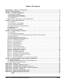
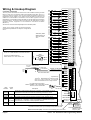
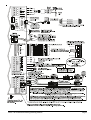
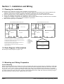
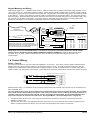
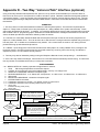
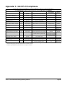
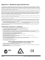
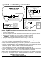
Table of Contents
Specifications, Features, and Benefits ..................................................................................................... 5
Wiring & Hookup Diagram ........................................................................................................................... 6
Section 1 - Installation and Wiring ............................................................................................................. 8
1.1 Planning the Installation ...................................................................................................................... 8
1.2 Parts Diagram & Descriptions ........................................................................................................... 8
1.3 Mounting and Wiring Preparation ....................................................................................................... 8
1.4 Control Wiring .................................................................................................................................... 9
Data Bus E.O.L. Termination - VERY IMPORTANT! .............................................................................. 12
Section 2 - Operating the System ............................................................................................................ 14
2.1 Introduction ....................................................................................................................................... 14
2.2 Powering Up (One Keypad) ............................................................................................................. 14
2.3 User Codes and Authorities .............................................................................................................. 14
2.4 Installer Program Code and Authorities ............................................................................................ 14
2.5 Keypad Overview ............................................................................................................................. 15
Keypad Menus ........................................................................................................................................ 16
Multi-area (Partition) Operation ............................................................................................................... 20
Section 3 - Programming The Control ..................................................................................................... 21
3.1 Introduction ....................................................................................................................................... 21
3.2 Local Keypad Programming ............................................................................................................. 21
3.3 Local or Remote Computer Programming (Ness-RP) and Anti-Takeover ........................................ 21
3.4 Area Partitioning ................................................................................................................................ 21
3.5 Communicator Setup Checklist ....................................................................................................... 22
3.6 Entering Installer Level Programming ............................................................................................... 22
Menu 01 - Bus Module Enrollment .......................................................................................................... 24
Menu 02 - User Code Options ................................................................................................................ 25
Menu 03 - Area Definitions ...................................................................................................................... 26
Menu 04 - Keypad Definitions ................................................................................................................. 28
Menu 05 - Zone Definitions ..................................................................................................................... 30
Menu 06 - Alarm Duration Timers ........................................................................................................... 33
Menu 07 - Global System Definitions ..................................................................................................... 34
Menu 08 - Telephone Account Setup ...................................................................................................... 38
Menu 09 - Area Reporting Codes ........................................................................................................... 40
Menu 10 - Zone Reporting Codes ........................................................................................................... 42
Menu 11 - Keypad F-Key Reporting Codes ............................................................................................ 43
Menu 12 - Sys Report Code Options & Codes ...................................................................................... 44
Menu 13 - User Report Codes ................................................................................................................ 46
Menu 14 - Wireless Definitions - (For future product release) ..................................................................... 47
Section 4 - PC Programming and Automation Capabilities .................................................................... 49
4.1 NESS-RP Software ......................................................................................................................... 49
4.2 Update/Verify Firmware in the Control and Peripherals ................................................................... 50
4.3 Automation Rules and Attributes ...................................................................................................... 51
Appendix A - Event Codes ........................................................................................................................ 58
Appendix B - Telephone Remote Control ............................................................................................... 60
Appendix C - Voice Message Vocabulary *RP only * ............................................................................. 62
Appendix D - Two Way “Listen-in/Talk” Interface (optional) ................................................................. 64
Appendix E - SIA CP-01 Compliance ........................................................................................................ 65
Appendix F - Regulatory Agency Statements .......................................................................................... 66
Appendix G - Additional Keypad Information .......................................................................................... 68
Index ............................................................................................................................. 71
NESS - M1 Installation and Programming Manual
Page 3
2200
Ohm
EOL
N.C. ZONE
2200
Ohm
EOL
N.C. ZONE N.O.
2200
Ohm
EOL
N.C. ZONE
2200
Ohm
EOL
N.C. ZONE
2200
Ohm
EOL
N.C. ZONE
2200
Ohm
EOL
N.C. ZONE
2200
Ohm
EOL
N.C. ZONE N.O.
NEG
2
3
N.O.
Z2
Cross Platform Control
Z3
16 Zones expandable to 208
HOUSE
PHONES
Black
T1
Green
TM
RING
Red
TIP
TELCO
LINE
NEG
N.O.
NEG
6
N.O.
Strip Wires to 7mm Length
N.O. Alarm Contacts
8
N.O.
Z8
N.C. ZONE N.O.
Z9
9
NEG
2200
Ohm
EOL
N.C. ZONE
2200
Ohm
EOL
N.C. ZONE
2200
Ohm
EOL
N.C. ZONE
2200
Ohm
EOL
N.C. ZONE
2200
Ohm
EOL
N.C. ZONE
2200
Ohm
EOL
N.C. ZONE
2200
Ohm
EOL
N.C. ZONE
10
11
N.O.
Z10
Z11
N.O.
NEG
12
13
N.O.
Z12
Z13
N.O.
NEG
14
15
N.O.
Z14
Z15
N.O.
NEG
16
N.O.
Z16
JP1
TELCO SEIZED
DIALLER ACTIVE
+SAUX
+12VDC Switched
Smoke Power
1.1 Amp PTC
protected
2WIRE
SMOKE
+SAUX
NEG
+VAUX
See Note 1.
+VAUX
+12VDC Auxiliary
Power (3)
1.25 Amp PTC
protected
UL Listed Transformer,
Class II, 16.5VAC, 45VA
Do not connect to a
switched outlet.
ON
+
-
+
-
-
U.L. Listed EOL Supervision Relay, ESL #204A
or equivalent. Use 2.2k Ohm EOL resistor.
Set JP1 to 'Normal'.
Note 1. Maximum COMBINED continuous
current drain from terminals +SAUX, +VAUX,
+VKP, OUT2 and J16 is 1.5A. Under alarm the
combined outputs should not exceed 2.5A
Note 2. a/ OUT 1 is for speakers 4 to 8 Ohms. If
using more than 2 speakers, use series/parallel
wiring to avoid going below a 4 ohm total load.
b/ OUT 2 may be set for speaker OR voltage.
Speaker Mode is set by default. In Speaker Mode
avoid going below 4 ohms total load. In Voltage
Mode (switched to ground, 1A max.) use a 12V
siren or screamer.
OUT 2 is supervised against open circuit (in both
Speaker and Voltage modes). If not used, install
a 2.2k Ohm resistor across the terminals to avoid
Output 2 Trouble condition.
c/ OUT 3 is a NO/NC dry contact relay rated 5A.
d/ OUT 7 to 16 are +12V switched POSITIVE
VOLTAGE outputs rated at 50mA max.
Note 3. Do not connect any neg terminal to earth
ground.
Note 4. If AC fails, low battery disconnect shuts
down the control at 10.2 volts. To start the control
with a good battery and no AC, short the silver
pads momentarily.
Replace the battery every 3-5 years and test it
regularly with the NESS-BLT Battery Life Tester.
N55
J4
Aux Data Bus
C
+
JP2
Select PLC Mode
1 WAY (PL513/PSC04)
2 WAY (TW523/PSC05)
To Zone Input
To Zone NEG
+SAUX
NEG
+VAUX
Serial Port for
Computer/NESSRP
PSC05 or
DO NOT
Lighting
Equivalent
Connect
to
Interface Conn.
a Phone
Line!
J5
J-16 Programmable Outputs
1
See Note 1
+12V
& Note 2d
NEG
OUT 16
OUT 15
OUT 14
OUT 13
OUT 12
OUT 11
OUT 10
OUT 9
OUT 8
OUT 7
LED indicates OUT3 is on
Dry Contact Relay
Example wiring for strobe
N/C
+VAUX
NEG
COM
See Note 2c
N/O
+
(Supervised)
+Horn speaker*
+
*Default
or 12V siren
- See Note 2b
Voice & Siren
- See Note 2a
100-171
Speaker
Audio Network Interface
O
NEG
-
I
-
B A + 1
J7
+VAUX
Data Bus Terminating Resistor
NEG
BATTERY
+-
Status
Reverse
Bat Leads SW1
Jumper to start with
no AC - See Note 4.
2200
Ohm
EOL
NEG
AC
16.5 V
AC
Power
Strip
4-Wire Smoke Detector - Any Zone
Z7
NEG
N.C. ZONE
B
A
All circuits are power limited except Telco and
Battery leads.
Z6
7
J3
1
RS232 CONN.
Z5
Testing of this system should be performed
regularly. Control panel specifications are subject
to change without notice.
12V Battery
7 to 18 Ah
www.ness.com.au
SYDNEY Ph 02 8825 9222 [email protected]
MELBOURNE Ph 03 9875 6400 [email protected]
BRISBANE Ph 07 3399 4910 [email protected]
PERTH Ph 08 9328 2511 [email protected]
ADELAIDE Ph 08 8277 7255 [email protected]
100-200 M1 control module
100-201 M1 GOLD control module
Serial number located below on base.
+VKP
DATA A
DATA B
NEG
RED
JP3
5
Z4
OUT 3
4
N.O.
ZONE 16
NORMAL
Page 4
ELK-M1
Yellow
R1
OUT 2
2200
Ohm
EOL
Z1
N.O.
OUT 1
2200
Ohm
EOL
1
1.25 Amp PTC
protected
GREEN
Keypad
WHITE
BLACK
Data Bus
See Note 1
Not Used
J2
Keypad &
Data Bus
J1
NEG
DATA B
DATA A
+12V
NESS - M1 Installation and Programming Manual
Specifications, Features, and Benefits
The M1 is available in two models, the ELK-M1 Standard and the ELK-M1G Gold. The features and benefits which are common to
both models is listed on the top section of this page. The bottom section highlights the key differences between both models.
General:
• Large zone capacity: 16 on-board zones expandable to 208
• Wireless capability: Up to 48 zones
• Two Way Listen-in interface
• Flash Memory - Allows field updates to firmware electronically
• RS-232 serial port to interface PCs and peripheral devices
• Time/Date stamped 512 event history log
• Menu driven, text keypad programming - no manual required!
• Voice announcement of alarms, zone descs, status, etc.
- 500+ Word/Phrase Vocabulary
- Link up to 6 words/phrases per announcement
- 10 custom recordable words/phrases
• 13 On-Board Outputs: 1 voice driver/siren, 1 siren driver/
voltage, 1 form “C” Relay, and 10 low current (50 mA) voltage
outputs
• Supports 4 wire (any zone) and 2 wire (zone 16) smoke
detectors
• Includes Fire alarm verification routine
• Can be partitioned into 8 areas and account numbers
• User Codes: 99 (4 or 6 digit) with assignable authority levels
• Arm levels: Away, Stay, Stay Instant, Nite, Nite Instant, Vacation
• Plug-in terminal blocks make service and pre-wires a snap!
• Hardware "watchdog" and nonvolatile EEPROM memory
• Supervised phone line, alarm output, and aux. overcurrent
Communications
• True V.22 bis Modem for fast reliable upload/download
• Optional Ethernet port for reporting, operation, programming
• Built-in Phone Remote Control makes any phone a keypad
• Integrated Voice Dialer uses vocabulary or custom words
• Communicator formats: SIA, Contact ID, 4 + 2, and Pager
• Installer telephone (buttset) test feature
• Ness-RP PC programming software with conflict resolution
to easily highlight differences between control and PC
- Dial-up, ethernet, RS-232 port, or local house phone jack
- Automatic answering machine bypass
Keypad
• Backlit, Large Character LCD Display, 16 x 2 lines
• Built-in Temperature Sensor
• Optional Plug-in Prox Access reader (26 bit Weigand format)
• Menu navigation keys and 6 programmable function keys
• Plug-in connector, only 4 wires to the control
• 1 Zone input and 1 Output Programmable per Keypad
• Programmable display of time, date, & temperature
• Displays system diagnostics and settings.
• Maximum Keypads allowed: 16
Comparisons of M1 and M1G (Gold)
•
•
•
•
•
•
•
•
•
Automation & Integration
• Create lifestyle enhancing comfort, convenience, and security
• Powerful “Whenever/And/Then” RULES Programming allows
almost any imaginable operation. No need to chain rules
together. Any single “Whenever” event can have one or more
ANDs and THENs (conditions and commands).
• Rules utilize easy to understand text based references
• Control lighting using RS-232 serial or 2-way Power Line
Control (PLC) ports including On, Off, Dim, All On, All Off
commands
• Transmit and receive custom serial ASCII strings
• Read Temperature Sensors - Communicate with Thermostats
• Turn on Tasks, Lights, Outputs via Keypad or Telephone
Remote
• Sunset/Sunrise calculation and activation built-in
Power Supply
• Heavy duty - 2.5 Amp power supply w/ 1.5 Amp continuous
• Dynamic battery test
• Master power switch and Low battery disconnect
• PTC (fuseless) resettable overload protection
• Multiple auxiliary power terminals
Ness Part Numbers and Accessories:
101-204 Standard M1 Control in 355mm x 355mm metal
enclosure
101-205 M1 GOLD Control in 355mm x 355mm metal enclosure
101 - 208 Ness power kit (power pack, battery & Dialler lead)
101 - 203
101 - 210
101 - 212
101 - 211
101 - 213
101 - 207
101 - 215
101 - 214
101 - 220
101 - 221
101 - 217
101 - 216
101 - 219
101 - 229
101 - 209
Keypad, LCD,16 character x 2 line
16 Zone (input) expander
16 Output expander, 8 Voltage / 8 Relays
16 Output expander, Voltage only
Relay board, 8 form ”C” relays
Data bus wiring hub
Ethernet Port Exp/Interface
Lighting, Thermostat Interface & Serial exp.
Mini prox reader for keypad
Wiegand 3rd party reader connection cable
Two Way Listen In Kit C/W Speaker and Mic
Two Way Listen-in module w/3 mic inputs
Speaker & Mic for Two Way Listen-in
Zone Temperature Sensor (-45 to 60C) (-50 to 140 F)
Ness-RP Technicians PC software, free with
1st Control purchase
ELK-M1 (Std)
Automation (“Whenever/And/Then”) Rules Capacity
100
Serial (RS232) Port Supported
1
Phone Number Capacity
4
Number of HVAC Thermostats Supported
2
Total Number of Outputs Supported
32
Advanced Lighting Options (Pre-set Dim, Extended, Levels, Scenes) Analog Zone Definitions Supported
Additional capacity for transmission of Serial ASCII Strings
Larger capability for events (time and date), task, lights, outputs
-
NESS - M1 Installation and Programming Manual
ELK-M1G (Gold)
528
8 w/expanders
8
16
205
Yes
Yes
Yes
Yes
Page 5
Wiring & Hookup Diagram
(Left Side Terminals)
This unit provides Residential fire alarm service when installed according to ANSI/
NFPA 72-1993. This unit provides Grade A Residential Burglar alarm service. In
conjunction with the enclosure, this unit also provides the following Commercial
Burglar alarm service: Grade A Local, Police Connect with Basic Line Security, and
Grades B & C Central Station. Transmission of the fire alarm signal to a fire alarm
headquarters or central station shall be permitted only with the approval of the authority
having jurisdiction. The burglar alarm signal shall not be transmitted to a police
emergency number, equipment is to be installed in accordance with NFPA
(985,55.1.P)
All circuits are current limited except telephone line and Battery leads.
Testing of this system should be performed regularly.
Control panel specifications are subject to change without
notice.
2200 (2k2) Ohm
2200 Ohm
EOL Resisters are
EOL Resistors are
Ness part # 605part # ELK-ER2200
222
2-Wire Smoke Circuit
Zone 16 can be configured as a 2-wire smoke zone.
Set JP1 to "2 WIRE SMOKE" and use 680 Ohm EOL
resistor, part # ELK-ER680
Use Only Compatible Detectors:
System Sensor: 1151, 2100, 2100T, 2151
GE: 429AT, 521BXT, 521B.
Hochiki America: SLK-835.
Detection Systems: DS250, DS250TH, DS282,
DS282TH, DS282THS, DS282THC.
Maximum Number = 20 Do not mix models.
2-Wire
Smoke Detector
680
Ohm
EOL
N.O. Alarm
Contacts
2200
Ohm
EOL
+
-
-
+
2200
Ohm
EOL
N.C. ZONE
2200
Ohm
EOL
N.C. ZONE
2200
Ohm
EOL
N.C. ZONE
2200
Ohm
EOL
N.C. ZONE
2200
Ohm
EOL
N.C. ZONE
2200
Ohm
EOL
N.C. ZONE
2200
Ohm
EOL
N.C. ZONE
2200
Ohm
EOL
N.C. ZONE
2200
Ohm
EOL
N.C. ZONE
2200
Ohm
EOL
N.C. ZONE
2200
Ohm
EOL
N.C. ZONE
2200
Ohm
EOL
N.C. ZONE
2200
Ohm
EOL
N.C. ZONE
2200
Ohm
EOL
N.C. ZONE
2200
N.C. ZONE
NEG Ohm
Z16
EOL
2200
Ohm
EOL
1
2
3
4
5
6
7
8
9
10
11
12
13
14
15
N.C. ZONE
16
N.O.
N.O.
N.O.
N.O.
N.O.
N.O.
N.O.
N.O.
N.O.
N.O.
N.O.
N.O.
N.O.
N.O.
ZONE 16
NORMAL
2WIRE
SMOKE
JP1
TELCO SEIZED
DIALER ACTIVE
4-Wire
Smoke Detector
+
To Zone Input
To Zone NEG
Switched +12 VDC Output
protected by 1.1A PTC.
-
Auxiliary +12VDC Power Outputs protected by
1.25A PTC NOTE:Maximum continuous current
drain from +VAUX,+VKP and J16 combined
must not exceed 900 mA or 2.5 Amps in alarm.
UL Listed Class II Transformer
DO NOT CONNECT TO A SWITCHED OUTLET
16.5VAC, 45VA ELK-TRG1640
TELCO
SEIZED
DIALER
ACTIVE
Power
Normal
State
Descriptions
OFF
Phone line is good and house phones are connected. If ON constantly, the phone
line may be bad. During remote mode this LED will be ON since the house phones
are then disconnected from the outside line & are being powered from control.
OFF
Dialer/Modem is idle. If ON, Dialer/Modem is in use (communicating).
ON
AC Voltage is present and power switch is turned ON. If OFF, check AC power.
1 blink with equal On and Off times is Normal. 2 fast blinks = Control running on
bootloader only. 4 fast blinks = Control is re-initializing it's EEPROM memory after
a firmware flash. 5 fast blinks = Memory/Operation overflow
Status
Regular 1
sec. Blink
Battery
Reversed
OFF
Z9
NEG
Z10
Z11
NEG
Z12
Z13
NEG
Z14
Z15
NEG
Z16
N.O.
U.L. Listed EOL Supervision Relay
(ESL #204 or Equivalent).
LEDS
Indicators
Z1
NEG
Z2
Z3
NEG
Z4
Z5
NEG
Z6
Z7
NEG
Z8
N.O.
18AWG Min.
+SAUX
NEG
+VAUX
NEG
+VAUX
NEG
+VAUX
NEG
AC
16.5 V
AC
POWER
STATUS
REVERSE
BAT LEADS
Battery is connected correctly. If ON, check battery lead connections.
Control requires AC power to start. However, for testing purposes it can
be started from battery ONLY by momentarily shorting these two pads.
Master Power Switch (SW1), disconnects AC and Battery power from control
Page 6
SW1
JUMPER TO START
WITH NO AC
Sealed
Lead Acid
BATTERY
+ -
12V Battery
5 to 18Ah
Test battery regularly with
ELK-BLT Battery Life Tester.
Replace every 3-5 years
NESS - M1 Installation and Programming Manual
Page 7
Section 1 - Installation and Wiring
1.1 Planning the Installation
The first step in any multi-zone security system installation is planning the job.
1. Read this entire manual to familiarize yourself with all system features and procedures before actually beginning the
installation. Read all the information regarding Underwriters Laboratories (UL) and NFPA requirements.
2. Perform a physical survey of the installation site. Use the diagrams below as a guide in planning the installation.
3. Discuss the installation requirements and applications with the customer.
4. Compare the installation requirements and applications with the factory default settings to determine what customized
programming is needed to meet the specific installation requirements.
5. Bench test the system prior to installation.
TYPICAL BURGLARY INSTALLATION LAYOUT
Bedroom 2
TYPICAL FIRE INSTALLATION LAYOUT
Bedroom 1
Bedroom 2
S
Kitchen / Dining
M
C
C
C
K
C
S
A
S
Bedroom 3
Living Room
C
Kitchen / Dining
M
A
Bedroom 3
Bedroom 1
S
Living Room
C
K
All perimeter openings below 18" should be provided with protection.
A Smoke Detector shall be located in each sleeping area and between
the sleeping areas and the main living area.
Early warning fire detection is best achieved by the installation of fire
detection equipment in the location shown above.
M
A
S
C
K
Legend
- Main Control
- Audible Alarm
- Smoke Detector
- Contact
- Keypad
First Floor
In homes basements or multiple levels at least one smoke detector
shall be on each level.
Basement
1.2 Parts Diagram & Descriptions
See Wiring & Hookup Diagram on pages 6 & 7.
1.3 Mounting and Wiring Preparation
Control Mounting
Remove all packing material and compare the system components with those in the figure above to familiarize yourself with
the part names. Mount the control in a secure, dry location where the ambient temperature inside the control box can remain
at 0’ to +49’ C (32‘ to 120°F). Choose a location that allows easy wiring to an unswitched power outlet and to a grounding
conductor for the control. A central location makes running system wiring easier. Remove control box knockouts that best suit
your wiring needs. Mount the control using the upper center slotted hole to level. Install and connect all necessary wiring for
the power transformer, detection loops, keypads and siren outputs.
Page 8
NESS - M1 Installation and Programming Manual
Keypad Mounting and Wiring
Ideal keypad height is 1.2 - 1.5 Meters above the floor. Select a location with an ambient temperature range between 0’ and
+49’ C (32° and 120° F). Avoid direct sunlight if possible. Fasten mounting plate to electrical box (or directly to wall) using flat
head screws to prevent shorts to the back of the circuit board. Keypads have a removable wiring plug for connecting to the M1
4-wire data bus. CAT5 or CAT6 eight (8) conductor cable is recommended for all Data Bus cables. The extra wires provide
data return paths. Splice the Black, Red, White, and Green wires from the removable wiring plug to the Data Bus cable. Plug
the connector into the back of the keypad. Tuck wires neatly into back plate and install Keypad on mounting plate. Each
keypad has connections for an optional programmable output and a programmable zone input.
Hookup Diagram for Keypad
Splice 6 Pin
Keypad
Wiringwiring
Assembly
totothe
using101-289
ELK-900-2
"B" Connectors.
Splice
6 pin Keypad
assembly
theData
Data Bus
cablecable
using Ness
“B” connnectors
BLACK
WHITE
GREEN
RED
BLUE
BROWN
Data Bus Cable
CAT5 or CAT6 Recommended
To Red (Pos) Wire
To Brown Wire
+
-
6
To BLACK (Neg) Wire
NOTE: The first batch of M1KP Keypads provided a switched
negative (pull to ground) output. Connect per diagram above.
These units have the letter "E" at the end of the ID number on the
lower back side of the board. EG: PC096E Boards with a letter
"F" or later provide the output as a switched positive.
Keypad 1
1
To BROWN Wire
Load (50mA max)
i.e. Relay, LED
See Note about
Data Bus
Termination
ELK-M1KP
Keypad
Wiring
Assembly
The optional Zone Input # or Output # is
determined by the Keypad Address.
+
-
Load (50mA max)
I.E. LED, Relay
Optional programmable Output from Keypad
To BLUE Wire
N.C. N.O.
To BLACK (Neg) Wire
2200
Ohm
EOL
Optional programmable Zone Input from Keypad
KP
Zone Output
Address #
#
1
193 193
2
194 194
3
195 195
4
196 196
5
197 197
6
198 198
7
199 199
8
200 200
KP
Zone Output
Address #
#
9
201 201
10 202 202
11 203 203
12 204 204
13 205 205
14 206 206
15 207 207
16 208 208
NOTE: Refer to the section titled Data Bus E.O.L. Termination for important information about how to handle multiple
homerun cables. NEVER SPLICE OR CONNECT WIRE WITH CONTROL POWER ON. Minimum cabling should be four
conductor 22 or 24 gauge. Maximum resistance per wire is 25 Ohms. Device placement beyond 300 mts is not
recommended.
1.4 Control Wiring
Zones 1 Thru 16
The zone input terminals on the control board are labeled Z1, Z2, thru Z16. There are 8 common negative terminals mixed
between every two zones with each negative to be shared by those two zones. Through programming each zone may be
configured for standard EOL supervised (end-of-line resistor) function, as well as normally closed or normally open with no
resistor required. By default each zone requires a 2,200 Ohm EOL supervision resistor at the furthest most remote end of the
2200
Ohm
EOL
N.C.
ZONE
2200
Ohm
EOL
N.C.
ZONE
1
2
N.O.
N.O.
Z1
NEG
Z2
Z3
detection device wiring. A combination of N/C (normally closed) and/or N/O (normally open) devices may be connected to an
EOL supervised zone.
Tip: The condition of any zone can be checked using a voltage meter across the zone and com terminals. A non-violated
zone should measure approximately 7.0 Volts DC. If the circuit is violated in an open condition, the voltage should rise to
13.8 VDC. If the circuit is shorted across the EOL resistor, the voltage should be 0 VDC. One of the Keypad Menus also
allows zone voltage to be viewed on the LCD screen. See Keypad Menus, “86-System Diagnostics” on [page 19].
1.
2.
Connect all alarm sensors to the zone wiring per the instructions provided by the sensor manufacturer and wiring
diagram on pages 6 & 7.
Connect each zone wire to the appropriate terminal. Each zone has an input terminal and a common (negative) return.
NOTE: A negative terminal is shared by every two zones and all negatives are common to each other.
NESS - M1 Installation and Programming Manual
Page 9
Two-Wire Smoke Zones (Zone 16)
To enable the use of two-wire smoke detectors on Zone 16, move Jumper JP1 (located just below Zone 16 terminals) to the
right side so that the two right hand pins are covered. Go to the installer programming mode, Menu 05 - Zone Definitions, and
program Zone 16 as a Fire zone (Def=10). Step to the next location and program Wire Type=6. NOTE Use only compatible
two-wire detectors. When jumper JP1 is set for two-wire operation, a 680 Ohm EOL resistor (furnished in the hardware
pack) must be used instead of the 2,200 Ohm. Maximum wire resistance must not exceed 60 Ohms.
Switched Power Connection (+SAUX)
Four-wire smoke detector and other devices that require a temporary power disruption in order to reset or unlatch from the
alarm state (i.e. smoke detectors, etc.) should be connected to the +SAUX 12 Volt DC switched power terminal. When a
smoke reset is performed, the operating voltage to these devices is momentarily interrupted.
Auxiliary Power Connections (+VAUX)
Motion detectors, glass breaks, etc. and other devices requiring unswitched 24-hour power should be connected to one of the
auxiliary terminals, +VAUX. All negative terminals on the terminal strip are at the same reference and may be used whenever
a common (circuit ground) negative is required. Use caution when wiring the control to distribute the load devices among the
supply and the negative terminals evenly. NOTE: Circuit ground refers to any negative terminal connection on this control.
This does not refer to the earth ground terminal or to the common terminals of Relay Output 3. These terminals are not at
the same voltage potential and should not be wired so that they are electrically connected to a negative.
PTC (Positive Temperature Coefficient) Circuit Breakers
The +VAUX Auxiliary power and J16 power output terminals are protected against shorts and overloads by a 1.25A PTC. A PTC
is a solid state, auto-restoring type of circuit breaker. The +SAUX Switched (Smoke) power output is protected by a 1.1A PTC.
The +VKP Keypad power output is protected by a 1.25A PTC. Output 2 is protected by a 1.25A PTC. NOTE: Sometimes it may
be necessary to remove power (unplug the outputs) for approx. 20 seconds after a short, to allow the PTC to reset. Even
if the short is no longer present, the remaining residual current draw may be so high that the PTC cannot determine that
the short is gone. If the PTC re-trips, check the field wiring and repair.
Transformer Primary Power Input (AC)
UL Listed Transformer,
Class II, 16.5VAC, 45VA
ELK
-TR
G1 6
40
+VAUX
NEG
AC
16.5 V
AC
POWER
STATUS
REVERSE
BAT LEADS
SW1
JUMPER TO START
WITH NO AC
+
BATTERY
+
RED
BLK
-
ELK-1280
12V Battery
Sealed Lead Acid
The control is powered by a 16.5 VAC, 40VA min., Class II (power limited) transformer (Ness part # 840-041). The specified
sized and rated transformer must be used to operate this control. The transformer must be connected to a 120 VAC, 24-hour
outlet not controlled by a switch other than an approved overcurrent protection device.
Connect the transformer to the AC Terminals using 16 to 18 gauge minimun wire. Do not exceed 15 meters between the
transformer and the control or run the AC power in a multiconductor with other system circuits. Leave the transformer
unplugged as well as the standby battery until all other connections have been made.
Standby Battery Connection
Connect the BLACK wire to the Neg (-) terminal on the battery, the connect the RED wire to the Pos (+) terminal on the battery.
The control is designed to operate with and recharge a 12 volt, sealed lead acid battery from 7Ah up to 18 Ah for backup of the
primary power supply. The control maintains a float charge for the battery of 13.8 VDC at 100 mA. This is in addition to the
continuous output of 1.5 Amps that the power supply maintains (see maximum current drains for UL Listed Systems).
Page 10
NESS - M1 Installation and Programming Manual
CAUTION: Do not reverse the battery leads! The control has special circuitry which helps protect it from battery reversal
damage for short durations. However, prolonged reversal of the battery leads may cause permanent damage. A reverse
battery warning LED is located to the left of the power On/Off switch. If this light is ON, turn the power off immediately
and correct the battery lead connections.
AC Failure, Low Battery, and Automatic Low Voltage Shutdown
During an AC power failure the battery automatically takes over and AC Fail trouble annunciates at the keypad. The
communicator can be programmed to report AC Fail to the Central Station after a time delay (see Menu 12, System Option 01).
If the battery voltage falls below 11.2 VDC a Low Battery Trouble condition will occur. The communicator can be programmed
to report Low Battery to the Central Station. The battery will continue to run the control until its voltage reaches 10.5 VDC, at
which time the control will disconnect and shut down to prevent a false alarm and damage to the battery. The AC Fail trouble
display will clear if the AC restores. However, the Low Battery Trouble requires a manual or automatic battery load test before
it will clear. An automatic battery load test is performed every 24 hours. See Section 2.2 for powering up the control.
Telephone Line Connection (R1,T1,T,R)
The telephone interface is connected by the use of an approved Mode 3 socket. This device allows the subscriber to
disconnect the control/communicator from the public switched telephone network in the event of a malfunction. The control is
equipped with line seizure so that the premises telephone service is interrupted during communication to the central station.
Connection to the approved socket is done with a Ness Dialler cord (Part # 450 -200) which connects the control terminals to
the mode 3 socket.
Outputs
There are 13 outputs on the main board. Outputs may be expanded utilizing output expander boards connected to the RS-485
4-wire Keypad data bus. Outputs 1 & 2 trip when any alarm is activated. All others must be enabled through the RP Rules
Programming and can be triggered by multiple conditions “events”. Do not exceed the current limits on voltage only outputs.
Output 1 is driven by an Audio Amplifier. It is designed to handle standard 8 ohm alarm speakers (never go below a total
connected load of 2 Ohms) for inside or outside use. This output is the source for voice announcements such as: Zone 1 not
ready, System Armed, Alarm Activated, etc., as well as alarm siren sounds. The initial start volume and the final volume can be
adjusted in programming to suit the application.
Output 2 is a traditional Alarm output. It is factory set to produce alarm siren sounds into standard 8 Ohm speakers (never go
below a total connected load of 4 Ohms). It can be alternately programmed to produce voltage only (12VDC) for driving selfcontained sirens or siren driver boards
Output 3 is a Single Pole Double Throw Relay with form “C” contacts (Com, N/O, and N/C).
ELK-924
+T -T NEG POS
Programmable Outputs (J16) OUT 7 - 16 are +12V switched
positive general purpose outputs rated at 50mA.
N/C COM N/O N/C COM N/O
+12V Red
Black
White
Green
Brown
Blue
Orange
Yellow
Violet
Grey
Pink
Tan
24V OPEN
+VAUX
NEG
OUT 16
OUT 15
OUT 14
OUT 13
OUT 12
OUT 11
OUT 10
OUT 9
OUT 8
OUT 7
D3
+12V
NEG
16
15
14
13
12
11
10
9
8
7
OUTPUTS
J16
Door
Strike
+
-
24V AC
Transformer
Using Output 7 (low current) with a sensitive relay to switch 24V AC to a Door Strike
Outputs 7, 8, 9, 10, 11, 12, 13, 14, 15, and 16 are low current, positive (+) voltage only, for driving LEDs, relays, etc. Outputs 4,
5, and 6 ARE NOT available from the main board. They can only be accessed with a data bus Output expander set to
address 1. This expander will replicate all the main board outputs, including outputs 4, 5, and 6.
Earth Grounding
Tests and studies have determined that the best results against lightning and transients are obtained by isolating the control
from ground. Do NOT connect any of the M1 terminals, especially the Neg. terminals to earth ground. Early production M1
circuit boards had a terminal marked “earth ground”. This terminal is no longer used on circuit board revision I or later.
However, ancilliary devices such as the ELK-950 Surge Protector on the incoming Telephone circuit are still recommended.
Keypad & Expanders on the RS-485 Data Bus (+VKP, Data A, Data B, Neg)
Keypads and data bus expander devices connect to the four terminals marked +VKP, Data A, Data B, and Neg. The keypad
plug-in wire harness color code is: Red +VKP, Green Data A, White Data B, and Black (-) Neg. The +VKP power terminal is
protected by an auto reset PTC device. In the event of a short circuit or malfunction, power will be removed from all devices
until the problem is resolved. Two (2) quick connect header pin plugs (J1 and J2) along the bottom of the board may be used
for temporary purposes I.E. bench testing using a four conductor ribbon cable. Do not use for permanent connections.
NESS - M1 Installation and Programming Manual
Page 11
Data Bus E.O.L. Termination - VERY IMPORTANT!
Unlike many controls, the M1 features a true RS-485 “differential” data bus operating at 38,400 baud (bits per second). This
is a relatively high speed by industry standards and was designed to ensure fast, accurate communications. As a result of
this high speed, data bus terminating resistors (120 Ohm resistors) are recommended in order to eliminate the possibility of
reflection errors caused by varying cable lengths, especially with multiple home run (star topology) cables.
Every M1 data bus device; keypad, zone, output expander, etc. and the control board has a built-in bus terminating resistor
(120 Ohm). Each terminating resistor is installed (activated) via a 2 pin header/jumper (2 Gold Pins) using a small black
shorting cap. The terminating resistors are marked JP2 on the keypads and JP1 on the expanders. From the factory, no
terminating resistors are installed (activated). The control hardware pack includes two of the small black shorting caps.
When one of the shorting caps is placed on the two gold pins, it installs (activates) the built-in 120 Ohm terminating resistor
across Data Lines A & B.
WARNING! The RS-485 Data Bus must NEVER have more than 2 terminating resistors header/jumpers installed. Reliability
and response will be negatively affected. See diagrams on opposite page.
Ideally, there should be no more than two home run data bus cables, with devices daisy chain connected along the two
cables and a terminating resistor (header/jumper) installed on the last device of each cable. However, if you prefer to home
run everything (3 or more), we highly recommend using 6 or 8 conductor cabling (CAT5 or CAT6 cable is ideal). At each
device, splice data wires A & B to 2 of the extra conductors so they return back to the control as A1 & B1. At the control, splice
the returning data wires A1 & B1 in series to data wires A & B going back out to the next device. Remember to install a
terminating header/jumper on the last wired device. Electrically the data wires are now in one long series circuit. Connect
the POS (+) and Neg (-) power wires of each device directly to the M1’s +VKP and Neg terminals. DO NOT SERIES THE
POWER WIRES as this will cause unnecessary voltage loss.
ELK-M1KP
RS-485 DATA BUS
+VKP
DATA A
DATA B
NEG
EGND
J2
J1
-
NEG
DATA B
DATA A
+12V
DATA BUS
JP3 Teminating Jumper
(Located beneath cover)
RE: Data Bus Termination Note
ELK-M1KP
ELK-M1XIN
Keypad 1
RS-485 Data Bus (Max. length is 4000 ft.
Max. bus devices vary by control.)
Keypad 2
RED
GREEN
ELK-M1XOV
WHITE
Jumper
Terminate
these two
devices.
ELK-M1KP
DO NOT Jumper
Terminate these devices.
Keypad 3
BLACK
DATA BUS TERMINATION IS VERY IMPORTANT!!
Ideal setup is 2 home run cables (4 wire) with daisy chained devices along each. The last device on each cable MUST have
a Terminating resistor installed (activated) via the gold 2 pin header/jumpers marked JP2 on keypads, JP1 on expanders.
Place a black shorting cap (see hardware pack) onto the 2 gold pins to install a 120 Ohm resistor across data lines A & B.
NOTE: Place a shorting cap on JP3 of Main Board it there is only 1 data bus cable. See diagrams on multiple cables.
WARNING! The RS485 Data Bus must NEVER have more that two (2) terminating resistors
header/jumpers installed. Reliability and response will be negatively affected!
Temporary Connection "Plug-in" jacks for RS-485 Data Bus (J1 & J2)
Local connection for Data Bus Devices ie: Keypads, etc. for testing purposes only.
Diagram for Daisy Chain Connection of Data Bus Devices Using Two (2) Home Run Cables
If home running 3 or more cables, use 6 conductor cables. At the device, make a three way splice of the data A wire, device A wire or terminal, and a
return data A1 wire (using one of the extra wires). Do the same for the data B wire. At the control, make a two way splice of the data A1 return wire (series
connection) to the outgoing data A wire of the next cable. Repeat for the data B wire. Terminate at the last device and the control JP3 ONLY!
RS-485 DATA BUS
+VKP
DATA A
DATA B
NEG
NOTE: The power wires are parallel
connected to the +VKP & Neg terminals.
RED
GREEN
WHITE
BLACK
cables
6 conductor
DATA
A1 A
DATA
A1 A
DATA
A1 A
B1
B1
B1
B
B
DATA
A1
B1
B
Install Teminating Jumper
Cap on this last device AND
on the control JP3.
+
Keypad
Keypad
-
Keypad
A
A1
SPARE
PAIR
See Diagram on next page for connection
of Optional Output and Zone Input
6
Conductor
Cable
B
1
RED +12
BLACK (-)
GREEN
WHITE
BLUE
BROWN
B
Keypad
Connect each device to the 6
conductor cable as shown.
For future
devices
Diagram for Daisy Chain Connection of Data Bus Devices Using 3 or More Home Run Cables.
Page 12
NESS - M1 Installation and Programming Manual
The ideal way to connect multiple home run cables is with an ELK-M1DBH Data Bus Hub. It accepts CAT5 or CAT6 cable with RJ45 plugs on the ends. It
does all the work of series connecting the DATA lines A & B. Terminate at the hub using the included RJ45 Terminating Plug in the first unused jack.
RS-485 DATA BUS
ELK-M1DBH Data Bus Hub
Mount M1DBH inside control.
Connect it to the M1 Data Bus
terminals using a 4 conductor cable.
J4
J2
J1
J3
J6
J5
J8
J7
J9
RJ45 Terminating Plug
Insert in first unused jack and
terminate the control at JP3.
DO NOT TERMINATE AT
ANY OF THE DEVICES!
CAT5 Cables
Keypad
Keypad
RJ45 Plug
/B
ht
rn
- Wrg/Wht
Pin1
COLOR CODE for CAT5 or CAT6 Data Bus Cable to ELK-M1DBH Data Bus Hub.
W
ht
B1
W
ht
Keypad
BLACK (-)
GREEN (A)
Gr
CAT5 or
CAT6 Cable
Spare
Spare
RED +12V
n/
A1 O
A
Front view
Pin1
8 - Brn/Wht
7 - Wht/Brn
6 - Org/Wht
5 - Wht/Blue
4 - Blue/Wht
3 - Wht/Org
2 - Grn/Wht
1 - Wht/Grn
+
Br
n/
W
ht
Keypad
/O
rg
BW
h t/G
rn
WHITE (B)
BLUE
BROWN
To BROWN Wire
To BLACK (Neg) Wire
+
-
Load (50mA max)
I.E. LED, Relay
Optional programmable Output from Keypad
Daisy Chain Connection of Data Bus Devices
Using ELK-M1DBH And CAT5 Cables.
To BLUE Wire
N.C. N.O.
To BLACK (Neg) Wire
2200
Ohm
EOL
Optional programmable Zone Input from Keypad
Setting the Data Bus Address and Enrolling Device(s) into the System
Keypads and expander devices communicate with the M1 over the RS-485 4-wire data bus. Each device must have a unique
address setting (from 1 to 16) within it's device type. Keypads are device TYPE 1, input (zone) expanders TYPE 2, output
expanders TYPE 3, etc. The purpose of device types is so that the address numbers can be re-used in each different device
type. It is OK to have a Keypad, a Zone Expander, and a Output Expander all set to address 2 and on the same data bus since
each device is a different device type. It is NOT OK to have duplications of addresses within the same device type. I.E.
Multiple keypads on the same control cannot be set to 'like' addresses.
ADDRESS: From the factory all keypads are set to address 1. Valid keypad addresses are 1 to 4 for the ELK-M1, or 1 to 16 for
the ELK-M1G. The first keypad on the system (Keypad 1) is automatically enrolled upon power up. Each additional keypad must
be assigned a unique address and then manually enrolled from “Menu 1 - Bus Module Enrollment”. (See M1 Instruction
Manual, Menu 01, for complete instructions on Bus Module Enrollment)
1. Press and hold the " * " key, followed by the F5 key . HOLD BOTH keys pressed for 5-10 seconds or until the LCD displays:
Exit when done. F1 Set Addr. (This is Keypad setup mode)
NOTE: This mode may also be accessed by removing power from the keypad (unplugging the data bus cable) and then
applying power while holding any key pressed.
2. Press the F1 key to display the current address setting.
3. Set the desired address by entering a number from 1 to X.
4. Press the Exit key when done.
ENROLLING:
1. Press the ELK key, then press 9 (or scroll up) to display 9 - Installation Programming. Press the
RIGHT arrow key to select this menu. The Installer Program Code (PIN) must be entered to access
this menu.
2. Enter the Installer Program Code. (See M1 Manual for the default Code)
3. The first Installer Programming menu displayed will be "Bus Module Enrollment"
4. Press the RIGHT arrow key to select this menu. "Enrolling Bus Modules" will display
5. The M1 transmit an enrollment message to all data bus devices, following by a display showing the
total Bus Modules that are enrolled. To view the enrolled devices and/or remove a device press the
RIGHT arrow key next to the word Edit.
6. Press the * or Exit keys to exit Installer Programming.
NESS - M1 Installation and Programming Manual
1234567890123456789012345
1234567890123456789012345
1234567890123456789012345
1234567890123456789012345
1234567890123456789012345
Auth. Required
1234567890123456789012345
1234567890123456789012345
1234567890123456789012345
Enter Valid Pin
1234567890123456789012345
1234567890123456789012345
1234567890123456789012345
1234567890123456789012345
1234567890123456789012345
1234567890123456789012345
01-Bus Module
1234567890123456789012345
1234567890123456789012345
1234567890123456789012345
1234567890123456789012345
Enrollment
1234567890123456789012345
1234567890123456789012345
1234567890123456789012345
1234567890123456789012345
1234567890123456789012345
XX Bus Modules
1234567890123456789012345
1234567890123456789012345
1234567890123456789012345
1234567890123456789012345
Enrolled, Edit r
1234567890123456789012345
1234567890123456789012345
Page 13
Section 2 - Operating the System
2.1 Introduction
For best operation during bench testing, all zones should be terminated with end of line resistors and the correct transformer
and battery should be connected to the unit. The control comes with factory default programming, allowing it to be bench
tested prior to installation. The factory default code for user 1 is 3456. This code is authorized to operate all user related
features of the system. The control is designed to accommodate the grouping of specific zones into partitions called areas
and by default, all zones are assigned to area #1. This is the most common mode in which the system operates. This section
of the manual gives an overview of powering up and basic keypad functioning.
2.2 Powering Up (One Keypad)
After all other connections have been made and checked thoroughly, the controls AC transformer and battery may be
connected. The Master Power Switch located on the lower left corner can then be turned on which will complete the AC and
battery connections into the control. Upon power up the control will perform self-diagnostics and auto-enroll the first keypad
(Keypad Address #1). Any additional keypads or expanders must be manually enrolled using Installer Level Programming.
See “Menu 01 - Bus Module Enrollment”.
NOTE: It is very important to make certain that every keypad, input expander, output expander, or any other data bus
device be assigned a unique data bus address within its type. See “MENU 01 - Bus Module Enrollment” for instructions
on setting keypad and expander addresses.
System Startup on Battery Only
Ordinarily, the control will not startup without AC power. However, if AC power is not available (new construction sites, field
testing, etc.) it is possible to start the control on battery ONLY! Locate the two silver pads on the lower left corner of the circuit
board. Take a small blade screwdriver and short these two pads. This will temporarily bypass the AC sensing circuit and
allow the control to startup. The On/Off power switch must be in the On position.
2.3 User Codes and Authorities
The control has 99 user passcodes plus one installer passcode. Each user code may be assigned specific authorities as to
what it is allowed to do. The authorities are assigned from the Installer level programming, however the code numbers and
user name is assigned from the keypad user menu 6 - Change User Codes. Only a Master authority level code or the
Installer code is allowed to access keypad user menu 6. The User’s Guide contains a description of panel
operations accessible to the user codes. Control operations accessed by the installer passcode are slightly different.
The Factory Default Code for User Code 1 is: 3 4 5 6 (Master Code)
(If the six digit code option is enabled, User Code 1 default will then be: 1 2 3 4 5 6)
The user code may be used for functions in a specific area or system-wide. Some options may be performed at any time,
even while the control is fully or partially armed. The menu system is designed to be next-step-oriented. After a brief
explanation of the options, the user should be able to begin operating the system immediately. For purposes of discussion,
the installer and the end consumer are both considered users, but have different capabilities.
2.4 Installer Program Code and Authorities
The installer code can access all the keypad user menus, including of course menu 9 - Installation Programming. The
Installer code also has limited arm/disarm privileges. It may be used to arm any area and may be used to disarm any area,
so long as that area was armed specifically by the installer code. The Installer code cannot disarm if an area was armed by
any user code. The Installer code may be used to silence 24hr alarms or a Burglary alarm in an area that was armed by the
installer or in an area that is not armed. The installer code may also be used to silence a trouble condition in a disarmed
area. See User’s Guide for a full description of arming and disarming procedures.
The Factory Default Installer Program Code is: 1 7 2 8 3 9
Page 14
NESS - M1 Installation and Programming Manual
2.5 Keypad Overview
Ready Light - This light is ON when all burglar zones are secure and the system is OK for arming. If this light is OFF, one or more zones are
violated (not secure). For maximum security, all zones should be secured before the system is armed.
If FLASHING, one or more force-armable zones are violated. Force arming temporarily excludes violated zone(s) from the system. However, if
a force armed zone becomes secure while the system is armed, it will automatically restore to service. This is handy for a garage door. The
system may be armed with the door up, but once the car is backed out and the door is closed, it will become secured.
Armed Light- This light will be ON when the system is armed. The mode of arm will be indicated by the LCD display and the Exit or Stay
lighted pushbuttons. This light will be OFF when the system is disarmed.
Exit Key - This lighted key may be programmed for single or double press arming to the AWAY (not occupied) mode. If the Exit light is ON the
system is armed and all perimeter sensors and interior motions are active. The Away key may be pressed during the exit delay time t to
convert from Away mode to Away Vacation mode. The Away Vacation mode is primarily for use with the Whenever/And/Then Rules programming of Elk-RP to invoke long term energy savings.
Stay Key - This lighted key may be programmed for single or double press arming to the STAY (occupied) mode. If the Stay light is ON the
system is armed and all interior zones are excluded (bypassed). Only perimeter doors and windows are active in the Stay mode. This key
may also be programmed to change to other Stay modes such as: Stay Instant, Stay Night, and Stay Night Instant. Since interior zones are
automatically excluded once the Stay mode is activated, the M1 allows this key to Stay arm even while one or more interior zones are
violated, provided they are programmed for “force arming”. The Stay Night mode re-activates any interior night zones. To prevent a false
alarm the control will not allow change to the Stay Night mode when a interior night zone is violated unless it is programmed for “Force arm”.
Chime Key - Chime produces an audible alert whenever certain doors, windows, or other selected zones are violated. There are four
different selections: Tone only, Voice, Tone/Voice, and Off. In the programming mode this key also functions as an insert character key for
text programming. The key light indicated when Chime is On.
Bypass Key - Pressing this key followed by a zone number and the bypass key again will exclude or bypass the selected zone. This
key may also be used to delete a character during text programming. When the Bypass key is lit, one or more zones are bypassed.
* Key - This key serves as a clear or reset key. If an error is made while entering digits, pressing this key clears the error. Three presses is
a master clear.
# Key - This key is currently a duplicate of the Bypass key.
Numerical Keys - These keys are used for entry of passcodes, programming, etc. Keys 2 - 9 also have an assigned alpha character
which are used for entering text.
Arrow Keys - The menu and arrow keys have powerful functionality used for both normal operation and programming. Pressing the Menu
key displays relative information according to each application. The arrow keys allow scrolling through all available options. The user can
activate or select the displayed option by pressing the right arrow key. Once an option has been selected, the user may be prompted for
a passcode. Additional sub-menu options may appear to assist. The user may return to the status screen by pressing the * key.
NESS - M1 Installation and Programming Manual
Page 15
123456789012345678901234567890
123456789012345678901234567890
123456789012345678901234567890
123456789012345678901234567890
READY TO ARM
123456789012345678901234567890
123456789012345678901234567890
123456789012345678901234567890
9:00AM 08/01/03
123456789012345678901234567890
123456789012345678901234567890
Keypad Menus
The control offers extended Menu Options via the center navigation “ELK” key. Some menus
may require a valid code to authorize. The Factory Default Code for USER Code 1 is: 3 4 5 6
(1 2 3 4 5 6 if the six digit code option is enabled)
Access to menus 1 to 5 can be restricted via programming to only Users that have “User Code Option 8” set. Menus 6 & 8
required a Master or Installer Code. Menu 9 requires the Installer Code. Press ELK to begin, then press the UP or DOWN
arrow key to select a menu. Enter a code if prompted. To select a menu press the RIGHT arrow key.
123456789012345678901234567890
123456789012345678901234567890
123456789012345678901234567890
123456789012345678901234567890
1-View/Control
123456789012345678901234567890
123456789012345678901234567890
123456789012345678901234567890
Automation Fncts
123456789012345678901234567890
123456789012345678901234567890
Allows viewing or controlling of the automation functions such as Tasks, Lighting, Outputs,
Temperature Sensor, Keypad Temperature, and Thermostats. Press the RIGHT arrow key to
select, then choose the desired function using the UP or DOWN arrow keys.
NOTE: The automation functions must be assigned and named using the NESS-RP software.
In most cases they cannot do anything unless they have been written into one of the
“Whenever/And/Then” automation rules.
123456789012345678901234567890
123456789012345678901234567890
123456789012345678901234567890
Tasks are like 1 button macros, performing multiple jobs with one push. To activate a task
123456789012345678901234567890
123456789012345678901234567890
1-Tasks
123456789012345678901234567890
123456789012345678901234567890
press the RIGHT arrow key and press UP or DOWN to scroll through the list of available tasks.
123456789012345678901234567890
123456789012345678901234567890
To jump directly to a particular task, enter it’s two digit number. Once the task is displayed, all
1234567890123456789012345678901
1234567890123456789012345678901
1234567890123456789012345678901
it takes to activate it is to press the # key. A rule to use the “Water the Lawn” task might be:
1234567890123456789012345678901
Water The Lawn
1234567890123456789012345678901
1234567890123456789012345678901
WHENEVER “Water the Lawn” IS ACTIVATED THEN TURN ON Valve 19 FOR 5 MINUTES, etc.
1234567890123456789012345678901
01:
#
Activates
1234567890123456789012345678901
1234567890123456789012345678901
123456789012345678901234567890
123456789012345678901234567890
123456789012345678901234567890
123456789012345678901234567890
123456789012345678901234567890
2-Lighting
123456789012345678901234567890
123456789012345678901234567890
123456789012345678901234567890
123456789012345678901234567890
123456789012345678901234567890
123456789012345678901234567890
123456789012345678901234567890
123456789012345678901234567890
123456789012345678901234567890
Kitchen Lights
123456789012345678901234567890
123456789012345678901234567890
123456789012345678901234567890
001:=Off, # to Chg
123456789012345678901234567890
Lighting allows the individual control of lights and/or appliances which have been assigned
through the Ness-RP software. Press the RIGHT arrow key to select Lighting, then press the
UP or DOWN arrow keys to scroll through the list. If you know the three digit number, you may
enter it to jump directly to that Lighting/Appliance. The current state of the unit will be
displayed. Press the # key to toggle (change) the unit from on > off or from off > on.
123456789012345678901234567890
123456789012345678901234567890
123456789012345678901234567890
123456789012345678901234567890
3-Outputs
123456789012345678901234567890
123456789012345678901234567890
123456789012345678901234567890
123456789012345678901234567890
123456789012345678901234567890
123456789012345678901234567890
123456789012345678901234567890
123456789012345678901234567890
123456789012345678901234567890
Pump Motor Cntrl
123456789012345678901234567890
123456789012345678901234567890
123456789012345678901234567890
001:=Off, # to Chg
123456789012345678901234567890
123456789012345678901234567890
Outputs might be relays or voltages used to actuate something like a motor, fan, pump, etc.
Outputs can be turned on or turned off from this menu. Press the RIGHT arrow key to select
Outputs, then press the UP or DOWN arrow keys to scroll through the list. If you know the
three digit number, you may enter it to jump directly to that Output. The current state of the
output will display. Press the # key to toggle (change) the output from on > off or from off > on.
123456789012345678901234567890
123456789012345678901234567890
123456789012345678901234567890
123456789012345678901234567890
4-Temperature
123456789012345678901234567890
123456789012345678901234567890
123456789012345678901234567890
Sensor
123456789012345678901234567890
123456789012345678901234567890
123456789012345678901234567890
123456789012345678901234567890
123456789012345678901234567890
123456789012345678901234567890
123456789012345678901234567890
Outside
123456789012345678901234567890
123456789012345678901234567890
123456789012345678901234567890
S01:=032 Degrees
123456789012345678901234567890
123456789012345678901234567890
123456789012345678901234567890
123456789012345678901234567890
123456789012345678901234567890
123456789012345678901234567890
5-Keypad
123456789012345678901234567890
123456789012345678901234567890
123456789012345678901234567890
Temperature
123456789012345678901234567890
123456789012345678901234567890
123456789012345678901234567890
123456789012345678901234567890
123456789012345678901234567890
Keypad 01
123456789012345678901234567890
123456789012345678901234567890
123456789012345678901234567890
K01:=073 Degrees
123456789012345678901234567890
123456789012345678901234567890
123456789012345678901234567890
123456789012345678901234567890
123456789012345678901234567890
123456789012345678901234567890
6-Thermostat
123456789012345678901234567890
123456789012345678901234567890
123456789012345678901234567890
Temperature
123456789012345678901234567890
123456789012345678901234567890
123456789012345678901234567890
123456789012345678901234567890
123456789012345678901234567890
123456789012345678901234567890
Hallway
123456789012345678901234567890
123456789012345678901234567890
123456789012345678901234567890
T01:=072 Degrees
123456789012345678901234567890
123456789012345678901234567890
123456789012345678901234567890
123456789012345678901234567890
123456789012345678901234567890
123456789012345678901234567890
2-Reset
123456789012345678901234567890
123456789012345678901234567890
123456789012345678901234567890
123456789012345678901234567890
123456789012345678901234567890
Smoke
Detectors
123456789012345678901234567890
123456789012345678901234567890
123456789012345678901234567890
123456789012345678901234567890
5 Seconds Smoke
123456789012345678901234567890
123456789012345678901234567890
123456789012345678901234567890
Output Reset
123456789012345678901234567890
123456789012345678901234567890
Remote “Zone” Temperature Sensors can be read from this menu. Press the RIGHT arrow
key to select this menu, then press the UP or DOWN arrow keys to scroll through the list of
available sensors. To jump directly to a particular sensor enter it’s two digit number. The
current temperature will be displayed. Press the * key to exit.
Keypad Temperature Sensors can be read from this menu. Press the RIGHT arrow key to
select this menu, then press the UP or DOWN arrow keys to scroll through the list of available
keypads. To jump directly to a particular keypad enter it’s two digit number. The current
temperature at the keypad will be displayed. Press the * key to exit.
Thermostats can be read from this menu. Press the RIGHT arrow key to select this menu,
then press the UP or DOWN arrow keys to scroll through the list of available thermostats. To
jump directly to a particular thermostat enter it’s two digit number. The current temperature at
the thermostat will be displayed. Press the * key to exit.
Used for resetting latched smoke detectors after a fire alarm activation..
Press the RIGHT arrow key to actuate the Reset Smoke Detector feature. This causes the
power to smoke detectors to be removed for 5 seconds. During this time all fire zones will be
ignored to keep an accidental alarm from occurring.
Continued on next page..
Page 16
NESS - M1 Installation and Programming Manual
123456789012345678901234567890
123456789012345678901234567890
123456789012345678901234567890
123456789012345678901234567890
3-Walk Test Area
123456789012345678901234567890
123456789012345678901234567890
123456789012345678901234567890
< Area? Name >
123456789012345678901234567890
123456789012345678901234567890
123456789012345678901234567890
123456789012345678901234567890
123456789012345678901234567890
123456789012345678901234567890
000of016 Tested
123456789012345678901234567890
123456789012345678901234567890
123456789012345678901234567890
A?-Violate Zones
123456789012345678901234567890
123456789012345678901234567890
123456789012345678901234567890
123456789012345678901234567890
123456789012345678901234567890
123456789012345678901234567890
123456789012345678901234567890
4-View History
123456789012345678901234567890
123456789012345678901234567890
123456789012345678901234567890
Log
123456789012345678901234567890
123456789012345678901234567890
123456789012345678901234567890
123456789012345678901234567890
123456789012345678901234567890
123456789012345678901234567890
L001:01/01 08:00
123456789012345678901234567890
123456789012345678901234567890
123456789012345678901234567890
AreaArmed 103A1
123456789012345678901234567890
123456789012345678901234567890
123456789012345678901234567890
123456789012345678901234567890
123456789012345678901234567890
5-View Status
123456789012345678901234567890
123456789012345678901234567890
123456789012345678901234567890
of all zones
123456789012345678901234567890
123456789012345678901234567890
123456789012345678901234567890
123456789012345678901234567890
123456789012345678901234567890
123456789012345678901234567890
123456789012345678901234567890
6-Change
123456789012345678901234567890
123456789012345678901234567890
123456789012345678901234567890
User Codes
123456789012345678901234567890
Requires Master or
Installer
Code
123456789012345678901234567890
123456789012345678901234567890
123456789012345678901234567890
123456789012345678901234567890
001:Sel
Prg
123456789012345678901234567890
123456789012345678901234567890
123456789012345678901234567890
<
User
Name
>
123456789012345678901234567890
123456789012345678901234567890
1234567890123456789012345678901
1234567890123456789012345678901
1234567890123456789012345678901
1234567890123456789012345678901
7--Automation
1234567890123456789012345678901
1234567890123456789012345678901
1234567890123456789012345678901
Custom Settings
1234567890123456789012345678901
1234567890123456789012345678901
Requires Master or
Installer
Code
1234567890123456789012345678901
1234567890123456789012345678901
1234567890123456789012345678901
1234567890123456789012345678901
1234567890123456789012345678901
CS01: 00:00Time
1234567890123456789012345678901
1234567890123456789012345678901
1234567890123456789012345678901
Sprklr On
1234567890123456789012345678901
123456789012345678901234567890
123456789012345678901234567890
123456789012345678901234567890
123456789012345678901234567890
123456789012345678901234567890
8-System
123456789012345678901234567890
123456789012345678901234567890
123456789012345678901234567890
Settings
123456789012345678901234567890
Requires Master or
Menu 3 permits a local walk test of all zones assigned to this keypad’s area. The siren(s) and
communicator are disabled during a walk test. Press the RIGHT arrow key to begin a Walk
Test. The keypad displays the total tested zones adjacent to the total number of zones involved.
When a zone is activated, it’s name is displayed across the bottom and can be audible if the
Chime mode is on.
Allows viewing of the past 512 activities stored in the history log. Press the RIGHT arrow key to
view the History Log. History activities include: Arm, Disarm, Alarm, Trouble, etc. The top line
displays the Log number, Mth/Day, Time, and event description.
L001 is always the most recent event. Press the UP or DOWN arrow keys to move forward and
back. Event 512 will be the oldest event. The bottom line displays the event description, the
extended data (zone, user, etc.) and the area number (A1-A8).
Allows viewing of the current status of all zones. Press the RIGHT arrow key to select. Press
UP or DOWN to scroll through the zones or enter a three digit number to jump directly to a
particular zone. I.E. for zone 16 enter 016. Press the * key to exit.
For changing a user code and/or name for codes which have been previously enabled by the
Installer. Only a Master code OR the installer code can access this menu. Press the RIGHT
arrow key to begin. Press UP or DOWN keys to locate a user, or enter 3 digits to jump. Press
RIGHT arrow key to view the existing code. To change, enter the new code digits and listen for 3
beeps to confirm. To edit the name, press the RIGHT arrow key once, then press the DOWN
arrow key. Enter the text using the letters on the keys. I.E. For “K” press the 5 key twice. Move
RIGHT or LEFT with the arrow keys. Press Chime to insert a space. Press Bypass to erases a
letter. The UP and DOWN arrow keys shift from upper to lower case letters. Press the ELK key
to save and exit.
.
Allows an end user to change up to 20 settings incorporated into an automation rule. These
settings can be: time of day, time duration (seconds), or a numeric value. Each custom setting
has a reference number (CS) and a text description: I.E. CS01: Sprkl On 00:00 [Time] implying
a time of day setting. Press the RIGHT arrow key to begin.
Press the UP or DOWN arrow keys to locate a setting, then press the RIGHT arrow key to
select. Enter the new value and press the ELK key to save and exit.
Menu 8 consists of 8 sub-menus used for advanced system settings. Press the right arrow key
and enter a valid user code. Press the UP or DOWN arrow keys to select a sub-menu or enter
the one digit number to jump directly to any sub-menu. I.E. enter 6 to jump to 86.
Installer Code
123456789012345678901234567890
123456789012345678901234567890
123456789012345678901234567890
123456789012345678901234567890
123456789012345678901234567890
81-Set Sys Clock
123456789012345678901234567890
123456789012345678901234567890
123456789012345678901234567890
24hr format
123456789012345678901234567890
To set the system clock press the RIGHT arrow key, then press the UP or DOWN arrow key to
select the day. Next, press the RIGHT arrow key to move to Date/Time setting. Enter two digits
for month, date, year, hour, and min. To exit press the * key.
123456789012345678901234567890
123456789012345678901234567890
123456789012345678901234567890
123456789012345678901234567890
82-Out1 Voice
123456789012345678901234567890
123456789012345678901234567890
123456789012345678901234567890
Adjust Volume
123456789012345678901234567890
123456789012345678901234567890
To set the volume for output 1 voice messages (non-alarm) press the RIGHT arrow key and set
desired volume with the UP or DOWN keys. There are 8 settings (0-7). WARNING: PROTECT
EARS! Each adjustment broadcasts a test message through Output 1. To exit press the * key.
123456789012345678901234567890
123456789012345678901234567890
To set keypad adjustments press the RIGHT arrow key. Then press the UP or DOWN keys to select
123456789012345678901234567890
123456789012345678901234567890
83-Keypad
123456789012345678901234567890
one of the three options.
123456789012345678901234567890
123456789012345678901234567890
Adjustments
123456789012345678901234567890
123456789012345678901234567890
1234567890123456789012345678901
1234567890123456789012345678901
1234567890123456789012345678901
To set keypad beep tones press the RIGHT arrow key, then select the desired tone using the UP or
1234567890123456789012345678901
1234567890123456789012345678901
1:Set Keypad
1234567890123456789012345678901
1234567890123456789012345678901
DOWN keys. There are 9 settings (0-8). When done, exit by pressing the * key.
1234567890123456789012345678901
Beep
Tone
1234567890123456789012345678901
1234567890123456789012345678901
1234567890123456789012345678901
1234567890123456789012345678901
To set key-press beep volume press the RIGHT arrow key, then select the desired volume using
1234567890123456789012345678901
2:Set Keypress
1234567890123456789012345678901
1234567890123456789012345678901
the UP or DOWN keys. There are 7 volume levels (1-7) plus Off (0). To exit press the * key.
1234567890123456789012345678901
Beep
Volume
1234567890123456789012345678901
1234567890123456789012345678901
1234567890123456789012345678901
1234567890123456789012345678901
1234567890123456789012345678901
To set backlight dim level press the RIGHT arrow key, then select the desired level using the UP or
1234567890123456789012345678901
3:Set Backlight
1234567890123456789012345678901
1234567890123456789012345678901
DOWN keys. There are 9 backlight levels (1-9) plus Off (0). The keypad automatically dims to this
1234567890123456789012345678901
Dim Level
1234567890123456789012345678901
1234567890123456789012345678901 setting after 30 seconds of no activity in order to save energy. To exit press the * key.
NESS - M1 Installation and Programming Manual
Page 17
123456789012345678901234567890
123456789012345678901234567890
123456789012345678901234567890
123456789012345678901234567890
123456789012345678901234567890
84-System
123456789012345678901234567890
123456789012345678901234567890
123456789012345678901234567890
Tests
123456789012345678901234567890
123456789012345678901234567890
123456789012345678901234567890
123456789012345678901234567890
123456789012345678901234567890
123456789012345678901234567890
1:Battery Test
123456789012345678901234567890
123456789012345678901234567890
123456789012345678901234567890
for 30 Seconds
123456789012345678901234567890
123456789012345678901234567890
123456789012345678901234567890
123456789012345678901234567890
123456789012345678901234567890
123456789012345678901234567890
123456789012345678901234567890
2:LCD Test
123456789012345678901234567890
123456789012345678901234567890
123456789012345678901234567890
123456789012345678901234567890
123456789012345678901234567890
123456789012345678901234567890
123456789012345678901234567890
123456789012345678901234567890
123456789012345678901234567890
123456789012345678901234567890
3:Communicator
123456789012345678901234567890
123456789012345678901234567890
123456789012345678901234567890
Manual Test
123456789012345678901234567890
123456789012345678901234567890
To perform system tests press the right arrow key. Then press the up or down arrow keys to
select one of the three tests.
The control’s standby battery is load tested automatically every 24hrs. However, it can also be
manually load tested anytime using this option. Press the right arrow key to start the test. The
battery is placed under load for 30 seconds and the battery voltage and system current is
displayed. If the battery falls below a set level, a Low Battery trouble will occur. If it’s necessary
to replace the battery, this test should be used to test and clear a Low Battery Trouble condition.
To test the keypad’s LCD screen press the RIGHT arrow key. The entire screen should appear
black indicating all pixels are working. To exit press the * key.
To manually test the communicator (dialer) press the RIGHT arrow key. Testing is done using
the first phone number that is programmed to send a test code. If there is no phone number
programmed to send a test code, the test will end. To exit this menu press the * key.
123456789012345678901234567890
123456789012345678901234567890
123456789012345678901234567890
123456789012345678901234567890
Send Test
123456789012345678901234567890
123456789012345678901234567890
123456789012345678901234567890
123456789012345678901234567890
123456789012345678901234567890
There are two types of test, silent and monitored. To silently send a test press the right
arrow key from this display. To hear the test using the inside speakers (OUT1) press the up
or down arrow key to bring up the following display.
123456789012345678901234567890
123456789012345678901234567890
123456789012345678901234567890
123456789012345678901234567890
Send Test w/
123456789012345678901234567890
123456789012345678901234567890
123456789012345678901234567890
speaker monitor
123456789012345678901234567890
123456789012345678901234567890
This unique feature permits you to hear or “monitor” a single communicator test using the
inside speakers (OUT1) eliminating the need for a telephone “Butt” set. Simply press the
right arrow key from this display to begin.
Silently
123456789012345678901234567890
123456789012345678901234567890
123456789012345678901234567890
123456789012345678901234567890
123456789012345678901234567890
Turn Butt Set
123456789012345678901234567890
123456789012345678901234567890
123456789012345678901234567890
Monitor Mode On
123456789012345678901234567890
123456789012345678901234567890
123456789012345678901234567890
123456789012345678901234567890
123456789012345678901234567890
Clear Pending
123456789012345678901234567890
123456789012345678901234567890
123456789012345678901234567890
Dialer Reports
123456789012345678901234567890
123456789012345678901234567890
Similar to above, this works for multiple communicator tests. Press the right arrow key to
enable. Each communicator transmission will be monitored until mode is canceled. Press
the star (*) key three times to cancel. Canceled automatically after 24hr daily battery test.
This special option allows any pending (not reported) dialer communications to be cleared
or cancelled. Typically this will be used only for initial installation and testing.
NOTE: ALWAYS NOTIFY THE MONITORING STATION BEFORE TESTING THE DIALER! If the test
should fail, a Comm Fail trouble will occur. To clear a Comm Fail the dialer must be able to
complete a good communication.
123456789012345678901234567890
123456789012345678901234567890
123456789012345678901234567890
123456789012345678901234567890
123456789012345678901234567890
85-Connect ‘RP’
123456789012345678901234567890
123456789012345678901234567890
123456789012345678901234567890
Remote Program
123456789012345678901234567890
123456789012345678901234567890
123456789012345678901234567890
123456789012345678901234567890
123456789012345678901234567890
123456789012345678901234567890
1:Seize Line
123456789012345678901234567890
123456789012345678901234567890
123456789012345678901234567890
Attended Mode
123456789012345678901234567890
123456789012345678901234567890
123456789012345678901234567890
123456789012345678901234567890
123456789012345678901234567890
2:Seize Line
123456789012345678901234567890
123456789012345678901234567890
123456789012345678901234567890
UnAttended Mode
123456789012345678901234567890
123456789012345678901234567890
To connect Ness’s Remote Program PC software (RP) via the user assisted method, press the
RIGHT arrow key and then select the connection mode with the UP or DOWN arrow keys.
1:Seize Line Attended Mode - 1) Allows RP connection to begin on an already established voice
connection between the control phone line and the RP Computer. 2) Also useful for manually
answering an incoming call from the RP Computer with programming Rings to Auto Answer.
2:Seize Line Unattended Mode - Pressing the RIGHT arrow key causes the control to dial the
programmed RP telephone number. The RP Computer must be in the “wait for call” mode.
1234567890123456789012345678901
1234567890123456789012345678901
1234567890123456789012345678901
This is a collection of tools for diagnosing system problems. Press the RIGHT arrow key and
1234567890123456789012345678901
86-System
1234567890123456789012345678901
1234567890123456789012345678901
enter a valid user code to begin. Press the UP or DOWN keys to select one of the four tools:
1234567890123456789012345678901
Diagnostics
1234567890123456789012345678901
1234567890123456789012345678901
1234567890123456789012345678901
1234567890123456789012345678901
1234567890123456789012345678901
1234567890123456789012345678901
This tool is useful for determining if data bus errors are accumulating. It displays the device
1234567890123456789012345678901
1:DataBusErrors
1234567890123456789012345678901
1234567890123456789012345678901
type and number of retries accumulated since the last power-up.
1234567890123456789012345678901
T2A1 Retry 00000
1234567890123456789012345678901
1234567890123456789012345678901
1234567890123456789012345678901
1234567890123456789012345678901
1234567890123456789012345678901
1234567890123456789012345678901
This tool displays the control’s voltage and the average current being drawn from the power
1234567890123456789012345678901
2:Sys Volt/Curr
1234567890123456789012345678901
1234567890123456789012345678901
supply.
1234567890123456789012345678901
13.8V
0.440Amps
1234567890123456789012345678901
1234567890123456789012345678901
1234567890123456789012345678901
1234567890123456789012345678901
This tool allows the voltage on each zone to be displayed in real time. It changes as contacts
1234567890123456789012345678901
1234567890123456789012345678901
3:Zone=001 Volts
1234567890123456789012345678901
or devices are violated. Press the RIGHT arrow key to begin.
1234567890123456789012345678901
1234567890123456789012345678901
Display Level
1234567890123456789012345678901
123456789012345678901234567890
123456789012345678901234567890
123456789012345678901234567890
123456789012345678901234567890
Zn=001 Volt=07.2 Use the UP or DOWN keys to scroll through each zone. The displayed information consists of:
123456789012345678901234567890
123456789012345678901234567890
123456789012345678901234567890
L04.6 H09.0 A132 the present zone voltage, the L low and H high alarm thresholds, and the analog (A to D)
123456789012345678901234567890
123456789012345678901234567890 equivalent of the zone voltage..
1234567890123456789012345678901
1234567890123456789012345678901
1234567890123456789012345678901
1234567890123456789012345678901
1234567890123456789012345678901
4:LastOnHookTele
1234567890123456789012345678901
1234567890123456789012345678901
1234567890123456789012345678901
Line V=57,+-20%
1234567890123456789012345678901
Page 18
This is a read only screen displaying the telephone line voltage during the last on-hook
condition. It is an approximate measurement accurate to only +-20%.
NESS - M1 Installation and Programming Manual
123456789012345678901234567890
123456789012345678901234567890
123456789012345678901234567890
123456789012345678901234567890
123456789012345678901234567890
87-Custom
123456789012345678901234567890
123456789012345678901234567890
123456789012345678901234567890
Message Record
123456789012345678901234567890
123456789012345678901234567890
123456789012345678901234567890
123456789012345678901234567890
123456789012345678901234567890
VM01 1 Block(s)
123456789012345678901234567890
123456789012345678901234567890
123456789012345678901234567890
Record<
Play>
123456789012345678901234567890
123456789012345678901234567890
123456789012345678901234567890
123456789012345678901234567890
123456789012345678901234567890
123456789012345678901234567890
123456789012345678901234567890
6 Sec Blocks=01
123456789012345678901234567890
123456789012345678901234567890
123456789012345678901234567890
Record< PlayAll>
123456789012345678901234567890
123456789012345678901234567890
123456789012345678901234567890
123456789012345678901234567890
123456789012345678901234567890
6 Sec Blocks=01
123456789012345678901234567890
123456789012345678901234567890
123456789012345678901234567890
Rec< LiftPhone!
123456789012345678901234567890
123456789012345678901234567890
123456789012345678901234567890
123456789012345678901234567890
123456789012345678901234567890
123456789012345678901234567890
VM01 1 Block(s)
123456789012345678901234567890
123456789012345678901234567890
123456789012345678901234567890
Record<
Play>
123456789012345678901234567890
123456789012345678901234567890
1)
2)
3)
4)
5)
6)
7)
This option is used in conjuction with a house telephone (microphone) to record up to 10
custom voice messages. Each message occupies a 6 second block. Two or more
consecutive blocks may be linked together for longer times. Total record time cannot exceed
60 seconds. These messages require the Ness-RP software, which utilize these messages
together with the built-in 500+ word vocabulary to construct voice phrases for many uses,
including the voice dialer. Press the RIGHT arrow key to begin custom message record.
Selects any one of the custom messages (VM01-VM10) for playback or recording. Press the
UP or DOWN arrow keys to select. To Play the selected message press the RIGHT arrow key.
The message will play through Output 1 speakers. To record a new message press the LEFT
arrow key. To exit press the * key.
This sets the number of consecutive 6 sec. record blocks. The default is 01 blocks which is
normally long enough for most applications. However, to create a longer message press the
RIGHT arrow key and enter the number 01 to 02, etc. NOTE: Creating longer messages
reduces the total number of custom messages. This screen also allows all messages to be
played “PlayAll” by pressing the RIGHT arrow key. When ready to record press the LEFT arrow
key.
This is the prerecord screen. To begin recording: 1) lift the house phone (off hook), 2) press
the LEFT arrow key, 3) start speaking. To stop recording press the “0” key. If stop is not
pressed, recording will automatically end after 6 sec. (or the total number of blocks times 6
seconds).
NOTE: A local house phone is used as the microphone. Installer programming menu 07,
option 1, must be set to a 1 in order for the local phone to be recognized by the control.
This will display as soon as recording has stopped. To play the new message press the
RIGHT arrow key. To record the message again press the LEFT arrow key and follow the
same procedures again. To exit press the * key.
Step by step summary of procedures for recording a custom message:
Verify that a house telephone is connected to the control’s T1 and R1 terminals and that Installer menu 07, option 1
is set to a 1. This allows the control to recognize the telephone and allow it to be used as a microphone.
Go to the user menu 8-System Settings by pressing the ELK key and entering 8. Press the r key and enter a valid
user code. Press 87 to reach the custom message record screen.
Using the Up/Down arrow keys, select the voice message to record VM01 to VM10. There are 10 custom
messages.
Press the l key and select the number of 6 second blocks for your message. Hint-rehearse and time the message,
if it is greater than 6 seconds then increase the number of consecutive blocks as required.
Lift the telephone handset and press the l key to begin the recording. The recording will not start until the handset
is off-hook and the l key is pressed.
Record your message by speaking into the handset. If the message is shorter than the amount of time selected
then press 0 to stop recording. Otherwise, recording will stop when the number of blocks is reached.
Press the Right arrow key to play the message. The message will be heard through the telephone handset if it is
still off-hook. Otherwise the message will be directed to the amplifier connected to output 1.
123456789012345678901234567890
123456789012345678901234567890
123456789012345678901234567890
123456789012345678901234567890
123456789012345678901234567890
9-Installation
123456789012345678901234567890
123456789012345678901234567890
123456789012345678901234567890
Programming (0)
123456789012345678901234567890
Requires
Installer
Code
From this menu you may press the RIGHT arrow to enter Installation Level Programming. If
the Installer Programming Code has not already been entered it will be required at this time.
REFER TO PAGE 22 FOR PROGRAMMING INSTRUCTIONS
NOTE: The Remote Programming RP software can be used to lockout certain local program
capabilities for “anti-takeover” purposes. The number in the lower right corner of this menu will
indicate the level of lockout as follows:
(0) = No lockout,
(1)=Lockout Telephone number programming - view everything,
(2)=Lockout ALL programming - view everything,
(3)=Lockout ALL Programming and Viewing. This can only be set or removed from the NessRP Remote Programming Software.
NESS - M1 Installation and Programming Manual
Page 19
Multi-area (Partition) Operation
123456789012345678901234567890
123456789012345678901234567890
123456789012345678901234567890
123456789012345678901234567890
0-Select Keypad
123456789012345678901234567890
123456789012345678901234567890
123456789012345678901234567890
Alternate Area
123456789012345678901234567890
123456789012345678901234567890
123456789012345678901234567890
123456789012345678901234567890
123456789012345678901234567890
123456789012345678901234567890
123456789012345678901234567890
Auth. Required
123456789012345678901234567890
123456789012345678901234567890
123456789012345678901234567890
Enter Valid Pin
123456789012345678901234567890
This menu allows the keypad to be mapped temporarily to any other area, allowing multiarea (partitioned) operation. The mapped area can be armed, disarmed, and otherwise
controlled just as if the keypad were permanently assigned to that area. It may also be
used to display a snapshot of all areas at once, showing the status of each area at once.
Press the RIGHT arrow key to select and display the following screen.
Enter a valid user code. The control does not allow (restricts) mapping or viewing of
areas that are not authorized for the user code. The following screen will be displayed:
MAPPING TO AN INDIVIDUAL AREA
123456789012345678901234567890
123456789012345678901234567890
123456789012345678901234567890
Enter the area number to be mapped OR scroll UP and DOWN with the arrow keys.
123456789012345678901234567890
Select Area- 1
123456789012345678901234567890
123456789012345678901234567890
123456789012345678901234567890
[Area Name]
123456789012345678901234567890
123456789012345678901234567890
1234567890123456789012345678901
1234567890123456789012345678901
1234567890123456789012345678901
Pressing the Exit or * key will map the Keypad to the area shown. The keypad will now
1234567890123456789012345678901
READY TO Arm
1234567890123456789012345678901
1234567890123456789012345678901
display the status, including LEDs and the LCD screen of the mapped area. For the next
1234567890123456789012345678901
[Area Name]
1234567890123456789012345678901
1234567890123456789012345678901 1 minute it will be possible to arm, disarm, bypass, etc. the mapped area from this
keypad. The 1 minute will be extended with each keypress. The keypad will return to its
primary assigned area after 1 minute of no keypress activity.
123456789012345678901234567890
123456789012345678901234567890
123456789012345678901234567890
123456789012345678901234567890
Select Area- 1
123456789012345678901234567890
123456789012345678901234567890
123456789012345678901234567890
[Area Name]
123456789012345678901234567890
123456789012345678901234567890
MAPPING TO A CONSOLIDATED DISPLAY OF ALL AREAS
Pressing the r RIGHT arrow key will map the Keypad to a consolidated ‘snapshot’
display of all areas which the user code was authorized to operate. This display permits
quick arming and disarming only. If a area is not ready to arm it will be necessary to map
individually (see steps above) to that area to view the violated zone(s) and either secure or
bypass them prior to arming.
1234567890123456789012345678901
1234567890123456789012345678901
1234567890123456789012345678901
1234567890123456789012345678901
1234567890123456789012345678901
Area# 12345678 The example at left shows that the user code was authorized for all 8 areas, as indicated
1234567890123456789012345678901
1234567890123456789012345678901
1234567890123456789012345678901
Status= Xr r r r r r r by a letter beneath each of the 8 area numbers. The letters show the status of each area.
1234567890123456789012345678901
A lower case “r” means the area is Ready to Arm, a lower case “n” means Not Ready, a
upper case “A” means Armed, and a upper case “X” means that area is the primary area
assigned to the Keypad which cannot be operated from the consolidated display.
1234567890123456789012345678901
1234567890123456789012345678901
1234567890123456789012345678901 The example at left shows that the user code was
1234567890123456789012345678901
1234567890123456789012345678901
Area# 12345678
1234567890123456789012345678901
1234567890123456789012345678901
1234567890123456789012345678901
Status= Xr r - - - - - The unauthorized area(s) have a “-” beneath them.
1234567890123456789012345678901
only authorized for areas 1, 2, and 3.
To change (toggle) the arm status of an area, press the number key representing the area
number. IMPORTANT: The area status is not “real time”. It is a snapshot taken when the
r RIGHT arrow key was pressed. If a zone has since become violated the area will still
be displaying “r”, however the letter will immediately change to “n” and the keypad will emit
an error tone when an attempt is made to arm by pressing the area number.
NOTE: This is a new feature which became available with firmware release version 4.2.5. The
firmware may be flash upgraded in older controls to add this capability.
Page 20
NESS - M1 Installation and Programming Manual
Section 3 - Programming The Control
3.1 Introduction
The Security functionality of the M1 Control can be programmed either from an ELK-M1KP LCD Keypad OR from the NESS-RP
PC Software. The keypad features a menu-driven “Text” based interface with simple Yes/No answers for most options. After
just a short amount of experience the average installer will not even require an instruction manual to keypad program the
control.
For the Automation functionality the NESS-RP PC Software is a requirement. The options and capabilities available for
automation are so unique and powerful that it takes a PC to make use of all the benefits. The M1 features a powerful
“Whenever/And/Then” RULES based programming that allows almost any imaginable operation.
3.2 Local Keypad Programming
There are two levels of operation for programming the control locally, user level and installer level.
- User level programming provides the ability to add, change, or delete user passcodes and names. It also allows custom
automation settings to be viewed and changed. A master user code is required to access the user code and custom settings
screens. User programming is explained in the User’s Guide.
- Installer level programming allows total customizing of the Security operating features. Only the installer code may access
this level. If the installer code is lost or forgotten, it is impossible to program the control locally. Anyone attempting
installer level programming should be familiar with the contents of this publication prior to programming the control panel. If
remote programming is used, it is possible to “lock out” or prevent takeover of a control by another installation company by
selecting “Lockout Local Prog.” This prevents the installer passcode from gaining access to programming via an LCD
keypad. The installer passcode may still be used for the non-programming functions described in Chapter 2. Lockout Local
Prog does not affect remote programming.
3.3 Local or Remote Computer Programming (NESS-RP) and Anti-Takeover
NESS-RP programming utilizes extensive error checking and security safeguards, including data encryption, password logon, serial number, and dealer assigned RP access code. The serial # identifies the control to RP while the RP access code
identifies the computer to the control prior to a programming session. RP loads the access code during the first connection. It
cannot be viewed or changed from local keypad programming. In addition to these safeguards, you can set an anti-takeover
option from RP which prevents certain keypad programming. Even a total default of the panel programming cannot reset the
anti-takeover option once it is set..
3.4 Area Partitioning
The control may be divided into 1 to 8 independent areas (partitions). Each area appears as a full-featured system, allowing
one control to be shared by multiple, independent departments within a common structure. Zones, User Codes, and
Keypads may be assigned to any 1 area up to the maximum number available. An example is a single business divided into
separate departments, each department occupied by different employees. Mount the control in a secure area (common utility
closet) with dedicated and uninterrupted AC power and telephone service. Then assign zones, codes, and keypads to each
department.
Output 1 siren/voice activates on all alarms, regardless of the area. The RP Software Rules can be used create additional
(separate) outputs. When reporting to the central station events like AC Power Failure, Automatic tests, Low Battery, etc., are
considered system reports and are transmitted using the Area 1 account number. If area partitioning is not desired, simply
designate all zones to a single area (Area 1) which is the factory default setting for zones 1-16.
COMMON AREA - Another popular feature is the ability to have one or more areas made “common” to Area 1. This is often
referred to as a “Vestibule Feature”. Any of the Areas 2 thru 8 may be made common to Area 1. The result is: Area 1 cannot be
armed until all its common areas are armed. Once armed, Area 1 will disarm if any common area becomes disarmed. This
is good for lobbies or vestibules shared by two or more businesses. Each business must have their own area keypad.
NOTE: If you want Area 1 to automatically arm when all its common areas become armed, use a Whenever/And/Then rule
from the RP software to do this.
NESS - M1 Installation and Programming Manual
Page 21
3.5 Communicator Setup Checklist
The Communicator (Dialer) in the M1 can dial up to 4 telephone numbers in addition to the RP computer. The more powerful
M1G can dial up to 8 phone numbers plus RP. Digital reporting formats include: Pulse 4+2, SIA, Contact ID, and Pager. There
is also a Voice format which can be commanded from the RP Rules Programming to call a business, home, or cellphone and
deliver a voice message. Use the following checklist for each required telephone number.
1.
2.
3.
4.
5.
6.
Under Menu 08 - Telephone Account Setup, select one of the telephone numbers and program the following:
Option 01: Select the desired reporting format - 0=Disable, 1=Contact ID, 2=SIA, 3=Pulse 4+2, 4=Pager, 5=Voice.
Note: The Voice format (5) cannot be enabled from keypad programming. It can only be programmed from the
Ness-RP Software using the Whenever/And/Then Rules.
Option 02: Set the priority for the first (primary number) to 0 = Always Report.
Option 03: Program the telephone number digits to be dialed. No special start or ending characters are required.
Option 04: Set the dial attempts to greater than 0. For Digital reports 8 is suggested. For Voice the max. is 2.
Option 05 Program the digits for the account number to report. Each area (partition) has its own Acct. Number.
Option 13: Select Yes to have Area info, Zone Alarms, Zone Restores, and Zone Unbypasses reported to this Tel #.
Option 14: Select Yes if you wish to have Zone Bypasses reported to this Tel #.
Option 15: Select Yes if you wish to have Zone Troubles reported to this Tel #.
Option 16: Select Yes if you wish to have User (Open/Close) Reports reported to this Tel #.
Option 17: Select Yes if you wish to have Global System Events (AC Fail, Low Battery, etc.) reported to this Tel #.
Option 18: Although not required, you may program a text name for each telephone number.
Under Menu 09 - Area Reporting Codes, select the area (partition) and program the desired options such as: Dialer
Delay, Alarm Abort, Auto Open/Closings, etc. then .
Under Menu 10 - Zone Reporting Codes, select the zone number and program the desired options such as: Zone Alarms,
Restores, Bypasses, or Trouble.
Option A: For Zone Alarm program a two digit code. To have the automatic SIA or Contact ID report codes transmitted
simply program a nonzero value. I.E. Program a 1 (01).
Option R: For Zone Restore program a two digit code. For automatic SIA or Contact ID codes program a 1 (01).
Option B: For Zone Bypass program a two digit code. For automatic SIA or Contact ID codes program a 1 (01).
Option T: For Zone Trouble program a two digit code. For automatic SIA or Contact ID codes program a 1 (01).
Under Menu 11 - F Key Reporting Codes, select and program the alarm code for each desired Keypad Panic Key. NOTE:
Keypad Panics only have Alarm report codes, they do not have restore codes. For automatic SIA or Contact ID codes
program a 1 (01).
Under Menu 12 - Sys Report Code Options & Codes, select and program each desired option such as: AC Fail, Low
Battery, Automatic Test, and other system wide options, including the time values for certain options. For automatic SIA or
Contact ID report codes program a 1 (01).
Under Menu 13 - User Report Codes, select and and program an Open or Close report code for any User(s) that you
wish to track arm/disarm events, including arm/disarm by the Installer Code or Ness-RP computer.
3.6 Entering Installer Level Programming
1.
Press the center ‘ELK’ key once followed by the DOWN arrow key until display reads “9-Installation Programming”. NOTE:
The keypad may beep and display the following:
2. Enter the Installer Program Code when required.
Press the right arrow key to select the “Installation Programming” option.
12345678901234567890123456789012123
12345678901234567890123456789012123
12345678901234567890123456789012123
12345678901234567890123456789012123
12345678901234567890123456789012123
12345678901234567890123456789012123
12345678901234567890123456789012123
12345678901234567890123456789012123
12345678901234567890123456789012123
12345678901234567890123456789012123
12345678901234567890123456789012123
Auth. Required
Enter Valid Pin
The Factory Default Installer Program Code is: 1 7 2 8 3 9
For security against unauthorized programming changes, the installer code should be changed from its factory default setting.
This can be done from Menu 07 - Globals System Definitions, Option 42.
Once the Installer Code has been entered, the first programming menu will display and a 4 minute timer will be started.
If there is no key-press activity during this time period the control will automatically exit from the programming mode. It
is easy to navigate around and between the programming menus and options using the up and down arrow keys. When
the correct menu or option is located, press the right arrow key to proceed into that menu.
Refer to the Quick Reference Guide on the following page to locate a particular menu or to see what options
appear under each menu. Refer to the individual menus and their option descriptions for details about each of the
programmable items.
Page 22
NESS - M1 Installation and Programming Manual
Page 23
Menu 03
Area Defs
Area 1
(1) Exit Delay 1
(2) Entry Delay 1
(3) Exit Delay 2
(4) Entry Delay 2
(5) Auto Stay
(6) Exit Restart
(7) Closing Ringback
(8) SglKey Quickarm
(9) DblKey Quickarm
(10) StayKeyScroll
(11) Stay Instant
(12) Night Scroll
(13) Night Instant
(14) StayChgArmed
(15) [Name]
Menu 02
User Code Auth.
User 1
(1) Area #
(2) Arm
(3) Disarm
(4) Bypass
(5) Access
(6) Temporary
(7) Master
(8) Menu 1-5
(9) Duress
(10) [Name]
Enrolling
-Disp Totat Modules
-Allow Module Edit
Menu 01
Bus Mod Enroll
Menu 05
Zone Defs
Zone 1
(1) Definition
(2) Type
(3) Area Assign
(4) Silent Alarm
(5) Dialer Delay
(6) Listen-In
(7) Bypass
(8) Force Arm
(9) Swinger
(10) Per. Trip
(11) Fast Loop
(12) Chime
(13) Cross Zn
(14) [Name]
Menu 04
Keypad Defs
Keypad 1
(1) Area Assgn
(2) Silent Entry
(3) Silent Exit
(4) Silent Chime
(5) Dark in 60 sec
(6) Show Date/Time
(7) Show Temp
(8) Show Area
(9) Byp Req Code
(10) F1 Key Def.
(11) F2 Key Def
(12) F3 Key Def
(13) F4 Key Def
(14) F5 Key Def
(15) F6 Key Def
(16) [Name]
Menu 07
Global Options
(1) Tel Remote
(2) 12hr TimeDisp
(3) DD/MM Disp.
(4) Celcius Disp.
(5) DST Observe
(6) Fast Loop Tm
(7) SlowLoop Tm
(8) Cross SelfVer
(9) Cross Zn Tm
(10) Aud Trbls
(11) 6 digit codes
(12) CodeLockout
(13) Common Area
(14) Out1 Yelp to Buz
(15) Out1 Start Vol.
(16) Out1 Max. Alm.
(17) Out1 Max. Voice
(18) Out1 Max. NonAlm
(19) Out1 ‘No Talk’
(20) Out1 Say Sys
(21) Out1 Say Alms
(22) Out1 Say Zn Status
(23) Out1 Say Sys Tbl
(24) Out1 Say Zn Tbl
(25) Out1 Say Chime
Menu 06
Cutoff Timers
(1) Burglar
(2) Fire
(3) Medical
(4) Police
(5) Carbon Mon
(6) Emergency
(7) Freeze
(8) Gas
(9) Heat
(10) Water
(11) Aux1 24hr
(12) Aux2 24hr
Menu 07
Global Options (cont.)
(26) Out 2 Change to Voltage
(27) Out 2 Delay Time
(28) Out 2 Sgl Alarm Lockout
(29) Rings til Answer
(30) Ring/Hang/Answer
(31) 2 Way Listen-in Enable
(32) 2 Way Callback Time
(33) CS Alm Verify Time
(34) Baud Rate Port 0
(35) Xmit Event Log
(36) Xmit Zone Changes
(37) Xmit Output Changes
(38) Xmit Task Changes
(39) Xmit Light Changes
(40) Xmit Keypad Keys
(41) Req Code User Menus 1-5
(42) Local Prog. Code
(43) Serial Number [Read Only]
(44) Software Ver. [Read Only]
(45) Default Control Options
(81) Default User Codes
(82) Default Areas Data
(83) Default Keypads Data
(84) Default Zones Data
(85) Default Zone Names
(86) Default Cutoff Timers
(87) Default Global Data
(88) Default Telephone Data
(89) Default Telephone Numbers
(90) Default Area Report Codes
(91) Default Zone Report Codes
(92) Default System Report Codes
(93) Default User Report Codes
(94) Default Voice Messages
(95) Default Wireless Definitions
(99) Default Entire Control Panel
Menu 09
Area Report Codes
Area 1
(1) Dial Delay Time
(2) Abort Code
(3) Cancel Time
(4) Cancel Code
(5) Close Auto
(6) Close Early
(7) Close Extended
(8) Fail to Close
(9) Late Close
(10) Keyswitch Close
(11) Duress Code
(12) Open After Alarm
(13) Open Early
(14) Fail to Open
(15) Open Late
(16) Keyswitch Open
(17) User Lockout
(18) Exit Error
(19) Fail to Comm
Menu 08
Telephone #’s & Accts
Telephone #1
(1) Always Report
(2) Number
(3) Format
(4) Attempts
(5) Acct #1
(6) Acct #2
(7) Acct #3
(8) Acct #4
(9) Acct #5
(10) Acct #6
(11) Acct #7
(12) Acct #8
(13) Report Area/Alm
/Rest/Unbypass
(14) Report Zn Bypass
(15) Report Zn Troubles
(16) Report User Op/Cl
(17) Report Sys Globals
(18) [Name]
Menu 12
System Rpt Codes
(1) AC Fail Delay
(2) AC Fail Code
(3) Auto Test Code
(4) TstTime hr:mm
(5) Days betweenTest
(6) Aux Overcurrent
(7) Exp Module Tbl
(8) Installer Begin
(9) Installer End
(10) Log 80% Full
(11) Low Battery
(12) Memory Error
(13) RP Download
(14) Tel Line Fault
(15) Output 2 Tbl
Menu 11
Keypad
Report Codes
Keypad 1
(1) F1 Key Alarm
(2) F2 Key Alarm
(3) F3 Key Alarm
(4) F4 Key Alarm
(5) F5 Key Alarm
(6) F6 Key Alarm
Menu 10
Zone Rpt Codes
Zone #1
Alarm Code
Restore Code
Bypass Code
Trouble Code
ELK-M1 and ELK-M1G QUICK REFERENCE - MENU PROGRAMMING
Menu 14
Wireless Defs
1: ReceiverOptions
(1) Receiver Size
(2) ZnBank(Start Zn)
(3) Reg Supv. Hrs.
(4) Fire Supv. Hrs.
2: Transmitter Opts
^ Select Transmitter
(1) Enable Xmtr.
(2) Supv. Type
(3) Enable Option 1
(4) Enable Option 2
(5) Keyfob User ID
3: Learn Transmitter
^ Select Transmitter
(1) Xmtr to Learn
(2) Push Xmtr
4: Keyfob Event Def.
(1) Button 1 Code
(2) Button 2 Code
(3) Button 3 Code
(4) Button 4 Code
(5) Button 5 Code
(6) Button 6 Code
(7) Button 7 Code
(8) Button 8 Code
User 101
- RP Computer
Upload/Download
(1) Open Code
Close Code
User 100
- Installer(1) Open Code
Close Code
Menu 13
User Rpt Codes
User #1
(1) Open Code
Close Code
123456789012345678901234567890121234
123456789012345678901234567890121234
123456789012345678901234567890121234
123456789012345678901234567890121234
123456789012345678901234567890121234
123456789012345678901234567890121234
123456789012345678901234567890121234
123456789012345678901234567890121234
123456789012345678901234567890121234
123456789012345678901234567890121234
123456789012345678901234567890121234
01-Bus Module
Enrollment
Menu 01 - Bus Module Enrollment
Press RIGHT arrow key to select this menu. Press UP or DOWN arrow keys to select
another menu. The ELK key backs up one menu level. To exit press the * or Exit key.
NOTE: Every data bus device: Keypad, Input (Zone) Expander, Output Expander, etc. MUST have a unique
address within its type. This menu is then used to enroll the device into the system. SEE DETAILS BELOW:
Bus Module Enroll
123456789012345678901234567890121234
123456789012345678901234567890121234
123456789012345678901234567890121234
123456789012345678901234567890121234
123456789012345678901234567890121234
123456789012345678901234567890121234
123456789012345678901234567890121234
123456789012345678901234567890121234
123456789012345678901234567890121234
123456789012345678901234567890121234
123456789012345678901234567890121234
Enrolling
Bus Modules
123456789012345678901234567890121234
123456789012345678901234567890121234
123456789012345678901234567890121234
123456789012345678901234567890121234
123456789012345678901234567890121234
123456789012345678901234567890121234
123456789012345678901234567890121234
123456789012345678901234567890121234
123456789012345678901234567890121234
123456789012345678901234567890121234
123456789012345678901234567890121234
123456789012345678901234567890121234
123456789012345678901234567890121234
123456789012345678901234567890121234
123456789012345678901234567890121234
123456789012345678901234567890121234
123456789012345678901234567890121234
123456789012345678901234567890121234
123456789012345678901234567890121234
123456789012345678901234567890121234
123456789012345678901234567890121234
123456789012345678901234567890121234
123456789012345678901234567890121234
123456789012345678901234567890121234
Description of Option
Press the RIGHT arrow key to select this menu and automatically start the bus enrollment
process. ALL data bus devices which are presently connected to the data bus should
become enrolled.
XX Bus Modules
Enrolled, Edit
The enrollment process only takes a few seconds. Once complete, this summary screen
will appear displaying the total number of bus modules that were found and enrolled. To
edit and/or view the devices individually, press the RIGHT arrow key one time.
Keypad
Addr=01
Each enrolled keypad/device can be viewed one by one. The first device will always be
Keypad 1 with a T1 (for type 1) and Addr=01 (for address 01). As explained below,
different kinds of devices can be identified by their device “Type”. Pressing the Up or Down
arrow keys will scroll through each enrolled device.
T1
123456789012345678901234567890121234
123456789012345678901234567890121234
123456789012345678901234567890121234
123456789012345678901234567890121234
123456789012345678901234567890121234
123456789012345678901234567890121234
123456789012345678901234567890121234
123456789012345678901234567890121234
123456789012345678901234567890121234
123456789012345678901234567890121234
123456789012345678901234567890121234
Keypad
T1
Addr=02 Remove
123456789012345678901234567890121234
123456789012345678901234567890121234
123456789012345678901234567890121234
123456789012345678901234567890121234
123456789012345678901234567890121234
123456789012345678901234567890121234
123456789012345678901234567890121234
123456789012345678901234567890121234
123456789012345678901234567890121234
123456789012345678901234567890121234
123456789012345678901234567890121234
123456789012345678901234567890121234
End Enrollment
0x Bus Modules
If a device is removed from the data bus, it should be removed by repeating the enrollment
process. The control will only enroll the devices that are connected. It will remove any
previously enrolled devices that it does not see.
After the last device is reviewed, the next press of the Up arrow key moves to the “End
Enrollment” screen which once again displays the total number of devices enrolled.
DATA BUS DEVICE TYPES AND ADDRESSES: Each data bus device is a specific “Device Type”. Keypads are TYPE
1, Input (Zone) Expanders are TYPE 2, Output Expanders are TYPE 3, Serial Port Expanders are TYPE 5. Any new
devices designed will be assigned a Device Type. Every data bus device MUST have a unique “Address” setting within
its type. Valid Input Expanders addresses are 2 to 13, Output Expander addresses are 1 to 13. The address determines
the starting and ending zone or output numbers for that expander. See chart below:
Addr Input Exp
1 = N/A (main bd)
2 = Zone 17-32
3 = Zone 33-48
4 = Zone 49-64
5 = Zone 65-80
Output Exp
Outputs 1-16
Output 17-32
Output 33-48
Output 49-64
Output 65-80
Addr
6=
7=
8=
9=
10 =
Input Exp
Zone 81-96
Zone 97-112
Zone 113-128
Zone 129-144
Zone 145-160
Output Exp.
Output 65-80
Output 97-112
Output 113-128
Output 129-144
Output 145-160
Addr Input Exp
11 = Zone 161-176
12 = Zone 177-192
13 = Zone 193-208
Output Exp.
Output 161-176
Output 177-192
Output 193-208
INPUT AND OUTPUT EXPANDER ADDRESSES: Locate the bank of four white (DIP) switches along the top edge of the
board. Each switch has a position of Off or On (0 or 1) and a binary value (1, 2, 4, 8). The addition of the binary values
(sum total) for the switches set to the On position determines the data bus address. For example: Data bus address 5
is set by placing switches 1 and 4 to the On position (1 + 4 = 5). All other switches must be in the down or Off position.
KEYPAD ADDRESSES: All keypads are factory set to address 1. Valid addresses are 1 to 4 for the ELK-M1, or 1 to 16
for the ELK-M1G. The first keypad on the system (Keypad 1) is automatically enrolled upon power up. Each additional
keypad must be assigned a unique address and then manually enrolled from “Menu 1 - Bus Module Enrollment”. To set
the address on a keypad do the following:
1. Hold down a key while applying power OR press and hold the (Asterisk) “ * ” and F5 keys for 5 seconds.
2. Press the F1 key, then use the UP or DOWN arrow keys to set the desired address number.
3. Press the EXIT key when done.
NOTE: If a device is removed from the data bus, it should be un-enrolled to prevent a trouble. To replace a
defective device, set the address to the same value as the old unit and initiate the Bus Enrollment process.
Page 24
NESS - M1 Installation and Programming Manual
12345678901234567890123456789012123
12345678901234567890123456789012123
12345678901234567890123456789012123
12345678901234567890123456789012123
12345678901234567890123456789012123
12345678901234567890123456789012123
12345678901234567890123456789012123
12345678901234567890123456789012123
12345678901234567890123456789012123
12345678901234567890123456789012123
12345678901234567890123456789012123
02-UserCode Optn
Code used to:
Menu 02 - User Code Options
Press RIGHT arrow key to select this menu. Press UP or DOWN arrow keys to select
another menu. The ELK key backs up one menu level. To exit press the * or Exit key.
Default Code for User Code 1 is: 3 4 5 6 Note: If six digit code option is enabled, the
default will be 1 2 3 4 5 6. See Menu 07 - Global System Definitions, Option G11
User Code Options
Description of Option
12345678901234567890123456789012123
12345678901234567890123456789012123
12345678901234567890123456789012123
12345678901234567890123456789012123
12345678901234567890123456789012123
12345678901234567890123456789012123
12345678901234567890123456789012123
12345678901234567890123456789012123
12345678901234567890123456789012123
12345678901234567890123456789012123
12345678901234567890123456789012123
12345678901234567890123456789012123
There are 99 potential User codes. User 1 (001) is the first to display. Press the right
arrow key to program, or press the up or down arrow keys to select another user. Enter
three digits to jump to a specific user. The user name is displayed along the bottom.
12345678901234567890123456789012123
12345678901234567890123456789012123
12345678901234567890123456789012123
12345678901234567890123456789012123
12345678901234567890123456789012123
12345678901234567890123456789012123
12345678901234567890123456789012123
12345678901234567890123456789012123
12345678901234567890123456789012123
12345678901234567890123456789012123
12345678901234567890123456789012123
This option assigns the areas(s) in which this code may be used. For example: if the
numbers 1,2, & 4 are displayed, the code may be used in those areas. To assign or
remove an area press the numbers keys 1 thru 8. Each press toggles the number on/off.
12345678901234567890123456789012123
12345678901234567890123456789012123
12345678901234567890123456789012123
12345678901234567890123456789012123
12345678901234567890123456789012123
12345678901234567890123456789012123
12345678901234567890123456789012123
12345678901234567890123456789012123
12345678901234567890123456789012123
12345678901234567890123456789012123
12345678901234567890123456789012123
Selects Arm privileges. If Yes, this code can Arm it’s assigned area(s) (see option 01
above) from a keypad that is also assigned to the desired area. If No, this code cannot be
used to Arm.
12345678901234567890123456789012123
12345678901234567890123456789012123
12345678901234567890123456789012123
12345678901234567890123456789012123
12345678901234567890123456789012123
12345678901234567890123456789012123
12345678901234567890123456789012123
12345678901234567890123456789012123
12345678901234567890123456789012123
12345678901234567890123456789012123
12345678901234567890123456789012123
12345678901234567890123456789012123
Selects Disarm privileges. If Yes, this user code can Disarm it’s assigned area(s) (see
option 01 above) from a keypad that is also assigned to the desired area. If No, this code
cannot be used to Disarm.
12345678901234567890123456789012123
12345678901234567890123456789012123
12345678901234567890123456789012123
12345678901234567890123456789012123
12345678901234567890123456789012123
12345678901234567890123456789012123
12345678901234567890123456789012123
12345678901234567890123456789012123
12345678901234567890123456789012123
12345678901234567890123456789012123
12345678901234567890123456789012123
A Yes allows this code to Bypass zones whenever Menu 04-Keypad Definitions, Option
09, “Byp Key Req PIN” is set to Yes. Code and Keypad must be in the same area.
Default value for both these options is No (code not required for bypass).
001: Sel
User 1
Prg
001 01:12345678
Code used inArea
001 02:=Yes
Arm with Code
001 03:=Yes
Disarm with Code
001 04:=Yes
Bypass with Code
12345678901234567890123456789012123
12345678901234567890123456789012123
12345678901234567890123456789012123
12345678901234567890123456789012123
12345678901234567890123456789012123
12345678901234567890123456789012123
12345678901234567890123456789012123
12345678901234567890123456789012123
12345678901234567890123456789012123
12345678901234567890123456789012123
12345678901234567890123456789012123
001 05:=No
Access with Code
A Yes allows this code to activate the Access Keypad Events 1313-1328 for the keypad
where code is entered. Use the Whenever/And/Then Rules from Ness-RP to assign an
output to this event for tripping a door strike or lock. Note: If this code is enabled for
arming, it will be necessary to press the Exit or Stay key to arm after the code.
12345678901234567890123456789012123
12345678901234567890123456789012123
12345678901234567890123456789012123
12345678901234567890123456789012123
12345678901234567890123456789012123
12345678901234567890123456789012123
12345678901234567890123456789012123
12345678901234567890123456789012123
12345678901234567890123456789012123
12345678901234567890123456789012123
12345678901234567890123456789012123
If Yes, this code can only disarm if the control was armed by it or another temporary code.
In other words: A temporary code cannot disarm the control if a regular code was used to
arm. A temporary code might be used for cleaning, repair personnel, etc.
12345678901234567890123456789012123
12345678901234567890123456789012123
12345678901234567890123456789012123
12345678901234567890123456789012123
12345678901234567890123456789012123
12345678901234567890123456789012123
12345678901234567890123456789012123
12345678901234567890123456789012123
12345678901234567890123456789012123
12345678901234567890123456789012123
12345678901234567890123456789012123
A Master Code can be used to review, change, or delete other users, and to modify
selected system options. Only one Master code is needed per system. For security
purposed, multiple Master codes are not recommended.
12345678901234567890123456789012123
12345678901234567890123456789012123
12345678901234567890123456789012123
12345678901234567890123456789012123
12345678901234567890123456789012123
12345678901234567890123456789012123
12345678901234567890123456789012123
12345678901234567890123456789012123
12345678901234567890123456789012123
12345678901234567890123456789012123
12345678901234567890123456789012123
001 08:=No
Menu 1-5 Allowed
When Menu 07 - Global System Definitions, Option 41, “Require Code User Menu 1-5” is
set to a Yes, this option is then used to set which codes are allowed to access Menus 1 5. NOTE: Menus 6, 7, and 8 are only available to a Master or Installer code.
12345678901234567890123456789012123
12345678901234567890123456789012123
12345678901234567890123456789012123
12345678901234567890123456789012123
12345678901234567890123456789012123
12345678901234567890123456789012123
12345678901234567890123456789012123
12345678901234567890123456789012123
12345678901234567890123456789012123
12345678901234567890123456789012123
12345678901234567890123456789012123
12345678901234567890123456789012123
If Yes, this code will cause a silent Duress or “holdup” alarm to activate when the code is
used to arm or disarm the system. CAUTION: The communicator report code MUST
also be programmed! This feature is dangerous and should be used with caution.
001 06:=No
Temporary Code
001 07:=Yes
Master Code
001 09:=No
Duress
12345678901234567890123456789012123
12345678901234567890123456789012123
12345678901234567890123456789012123
12345678901234567890123456789012123
12345678901234567890123456789012123
12345678901234567890123456789012123
12345678901234567890123456789012123
12345678901234567890123456789012123
12345678901234567890123456789012123
12345678901234567890123456789012123
12345678901234567890123456789012123
001 10:Usr Name
User1
To edit the User (Name) text press the left arrow key. Enter text using the number keys.
I.E. For a “K” press the 5 key twice. To move the cursor, press the RIGHT or LEFT arrow
keys. The Chime key inserts a space, the Bypass key erases 1 digit. The up/down keys
to toggle between upper and lower case. Press the ELK key when complete.
NESS - M1 Installation and Programming Manual
Page 25
123456789012345678901234567890121234
123456789012345678901234567890121234
123456789012345678901234567890121234
123456789012345678901234567890121234
123456789012345678901234567890121234
123456789012345678901234567890121234
123456789012345678901234567890121234
123456789012345678901234567890121234
123456789012345678901234567890121234
123456789012345678901234567890121234
123456789012345678901234567890121234
03-Area
Definitions
Area Defintions
123456789012345678901234567890121234
123456789012345678901234567890121234
123456789012345678901234567890121234
123456789012345678901234567890121234
123456789012345678901234567890121234
123456789012345678901234567890121234
123456789012345678901234567890121234
123456789012345678901234567890121234
123456789012345678901234567890121234
123456789012345678901234567890121234
123456789012345678901234567890121234
A1: Sel
Area 1
Prg
123456789012345678901234567890121234
123456789012345678901234567890121234
123456789012345678901234567890121234
123456789012345678901234567890121234
123456789012345678901234567890121234
123456789012345678901234567890121234
123456789012345678901234567890121234
123456789012345678901234567890121234
123456789012345678901234567890121234
123456789012345678901234567890121234
123456789012345678901234567890121234
123456789012345678901234567890121234
A1 01:=060
Exit Delay1 Time
123456789012345678901234567890121234
123456789012345678901234567890121234
123456789012345678901234567890121234
123456789012345678901234567890121234
123456789012345678901234567890121234
123456789012345678901234567890121234
123456789012345678901234567890121234
123456789012345678901234567890121234
123456789012345678901234567890121234
123456789012345678901234567890121234
123456789012345678901234567890121234
A1 02:=030
Entry Delay1Time
Menu 03 - Area Definitions
Press RIGHT arrow key to select this menu. Press UP or DOWN arrow keys to select
another menu. The ELK key backs up one menu level. To exit press the * or Exit key.
Description of Option
Of the 8 potential areas (partitions), Area 1 is the first to display. Press the right arrow
key to program, or press the up or down arrow keys to select another area. To jump to a
specific area enter the number (1-8). The area name is displayed on the bottom.
The amount of exit time in seconds for all zones programmed as Exit Delay 1. Range is
045 to 255 seconds. Default value is 060. NOTE: Due to the way force arm works, if
an Exit Delay 1 zone also has force arm enabled, its exit time will be the greater
of the time values for Exit Delay 1 or Exit Delay 2. Do not enable force arm on
Exit Delay 1 zones if this operation is not desired.
The amount of entry delay time in seconds for zones programmed as Entry Delay 1.
Range is 030 to 255 seconds. Default value is 030.
123456789012345678901234567890121234
123456789012345678901234567890121234
123456789012345678901234567890121234
123456789012345678901234567890121234
123456789012345678901234567890121234
123456789012345678901234567890121234
123456789012345678901234567890121234
123456789012345678901234567890121234
123456789012345678901234567890121234
123456789012345678901234567890121234
123456789012345678901234567890121234
The amount of exit delay time in seconds for zones programmed as Exit Delay 2. Range
is 045 to 255 seconds. Default value is 060. See note above regarding force arm
and Exit Delay 1 zones.
123456789012345678901234567890121234
123456789012345678901234567890121234
123456789012345678901234567890121234
123456789012345678901234567890121234
123456789012345678901234567890121234
123456789012345678901234567890121234
123456789012345678901234567890121234
123456789012345678901234567890121234
123456789012345678901234567890121234
123456789012345678901234567890121234
123456789012345678901234567890121234
The amount of entry delay time in seconds for zones programmed as Entry Delay 2.
Range is 030 to 255 seconds. Default value is 030.
123456789012345678901234567890121234
123456789012345678901234567890121234
123456789012345678901234567890121234
123456789012345678901234567890121234
123456789012345678901234567890121234
123456789012345678901234567890121234
123456789012345678901234567890121234
123456789012345678901234567890121234
123456789012345678901234567890121234
123456789012345678901234567890121234
123456789012345678901234567890121234
If Yes, the control will switch from AWAY mode to STAY mode at the end of the exit delay
time if no exit zone is violated (no exit detected). NOTE: This tracks the longest of the
two exit timers. All interior zones are bypassed in the STAY mode. Default value is No.
A1 03:=060
Exit Delay2 Time
A1 04:=030
Entry Delay2Time
A1 05:=No
AutoStay No Exit
123456789012345678901234567890121234
123456789012345678901234567890121234
123456789012345678901234567890121234
123456789012345678901234567890121234
123456789012345678901234567890121234
123456789012345678901234567890121234
123456789012345678901234567890121234
123456789012345678901234567890121234
123456789012345678901234567890121234
123456789012345678901234567890121234
123456789012345678901234567890121234
123456789012345678901234567890121234
A1 06:=Yes
Exit1TimeRestart
If this option is set to Yes (default), the exit procedures will be affected in three ways:
1) ADDITIONAL EXIT1 “GRACE” FEATURE - During the initial Exit Delay 1 time if the
zone violates a second time and restores, the exit timer will automatically restart one
time. I.E. If the Exit1 door is opened, closed, and then opened again the timer will restart.
NOTE: This only works on Exit Delay 1 zones and the timer only restarts one time.
It does NOT work if the zone is enabled for force arm! This features complies with
the SIA CP-01 false alarm reduction standard.
* SIA
CP-01
2) SPOUSE “LEAVE FOR WORK” OR “LET PET OUT” FEATURE - If the system is
armed in one of the Stay modes, a User may press the Exit key to re-start the exit delay
time in order to open an exit/entry door and leave for work. The system remains in the
Stay mode for remaining family members that are still in the house. This can also be
used to let a pet outdoors. When the pet is ready to come back inside the User simply
presses the Exit key again to restart the timer.
3) GOING FROM STAY MODE TO AWAY MODE - If the system is armed in one of the
Stay modes, a User may change the arm mode to Away. This is done by pressing the
Exit key twice in short succession (within 3 seconds) and leaving the building.
Exit Error If an entry/exit zone is violated at the time the Exit Delay time expires, the Exit Error Feature will be * SIA
CP-01
activated. The local siren will sound immediately and the Entry Delay warning will begin. If the control is not
disarmed before the Entry Delay expires, the communicator will report the alarm along with an Exit Error code,
provided these codes are programmed. An Exit Error event flag will also be set which can be used by the
“Whenever/And/Then” rules (refer to the Ness-RP software) to sound a siren, or blink a light, or whatever.
Exit Error feature complies with the SIA CP-1 false alarm reduction standard.
Page 26
NESS - M1 Installation and Programming Manual
Menu 03 - Area Definitions (continued)
Area Definitions
12345678901234567890123456789012123
12345678901234567890123456789012123
12345678901234567890123456789012123
12345678901234567890123456789012123
12345678901234567890123456789012123
12345678901234567890123456789012123
12345678901234567890123456789012123
12345678901234567890123456789012123
12345678901234567890123456789012123
12345678901234567890123456789012123
12345678901234567890123456789012123
A1 07:=No Send
Closing Ringback
Description of Option
If Yes, a Closing Ringback signal (otherwise known as closing report successful) will be
sent to all the keypads when the Communicator transmits a closing report and the Central
Station Receiver kissoff (acknowledgement) is received. The Exit Delay time will be
restarted at this time. The default value is No.
12345678901234567890123456789012123
12345678901234567890123456789012123
12345678901234567890123456789012123
12345678901234567890123456789012123
12345678901234567890123456789012123
12345678901234567890123456789012123
12345678901234567890123456789012123
12345678901234567890123456789012123
12345678901234567890123456789012123
12345678901234567890123456789012123
12345678901234567890123456789012123
12345678901234567890123456789012123
If Yes, the control can be armed by a single press of the Exit or Stay keys. No code is
required except to disarm. Note: This option cannot be set to Yes if “Dbl Key Quick
Arm” (see below) is set to Yes. The default value is Yes.
12345678901234567890123456789012123
12345678901234567890123456789012123
12345678901234567890123456789012123
12345678901234567890123456789012123
12345678901234567890123456789012123
12345678901234567890123456789012123
12345678901234567890123456789012123
12345678901234567890123456789012123
12345678901234567890123456789012123
12345678901234567890123456789012123
12345678901234567890123456789012123
A1 09:=No
DblKeyQuickArm
If Yes, the system can be armed by a double press of the Exit or Stay keys. The second
press must follow the first very quickly. Note: This option cannot be set to Yes if “Sgl
Key Quick Arm” (see above) is set to Yes. The default value is No.
12345678901234567890123456789012123
12345678901234567890123456789012123
12345678901234567890123456789012123
12345678901234567890123456789012123
12345678901234567890123456789012123
12345678901234567890123456789012123
12345678901234567890123456789012123
12345678901234567890123456789012123
12345678901234567890123456789012123
12345678901234567890123456789012123
12345678901234567890123456789012123
A1 10:=Yes
Stay Key Scroll
If Yes, the Stay key may be pressed during the exit delay time to scroll (step) through the
selected levels of Stay arming. I.E. Stay Instant, Stay Night, etc. The options below
select the levels that will be available. The default value is Yes.
12345678901234567890123456789012123
12345678901234567890123456789012123
12345678901234567890123456789012123
12345678901234567890123456789012123
12345678901234567890123456789012123
12345678901234567890123456789012123
12345678901234567890123456789012123
12345678901234567890123456789012123
12345678901234567890123456789012123
12345678901234567890123456789012123
12345678901234567890123456789012123
If Yes, AND option 10 is set to Yes, multiple presses of the Stay key during exit delay will
be able to scroll to the Stay Instant arming level. The default value is No.
12345678901234567890123456789012123
12345678901234567890123456789012123
12345678901234567890123456789012123
12345678901234567890123456789012123
12345678901234567890123456789012123
12345678901234567890123456789012123
12345678901234567890123456789012123
12345678901234567890123456789012123
12345678901234567890123456789012123
12345678901234567890123456789012123
12345678901234567890123456789012123
12345678901234567890123456789012123
If Yes, AND option 10 is set to Yes, multiple presses of the Stay key during exit delay will
be able to scroll to the Stay Night arming level. The default value is Yes.
A1 08:=Yes
Sgl Key Quickarm
A1 11:=No
StayInstantScr
A1 12:=Yes
Night Scroll
12345678901234567890123456789012123
12345678901234567890123456789012123
12345678901234567890123456789012123
12345678901234567890123456789012123
12345678901234567890123456789012123
12345678901234567890123456789012123
12345678901234567890123456789012123
12345678901234567890123456789012123
12345678901234567890123456789012123
12345678901234567890123456789012123
12345678901234567890123456789012123
A1 13:=No
NightInstantScr
12345678901234567890123456789012123
12345678901234567890123456789012123
12345678901234567890123456789012123
12345678901234567890123456789012123
12345678901234567890123456789012123
12345678901234567890123456789012123
12345678901234567890123456789012123
12345678901234567890123456789012123
12345678901234567890123456789012123
12345678901234567890123456789012123
12345678901234567890123456789012123
A1 14:=No
StayChgIfArmed
12345678901234567890123456789012123
12345678901234567890123456789012123
12345678901234567890123456789012123
12345678901234567890123456789012123
12345678901234567890123456789012123
12345678901234567890123456789012123
12345678901234567890123456789012123
12345678901234567890123456789012123
12345678901234567890123456789012123
12345678901234567890123456789012123
12345678901234567890123456789012123
12345678901234567890123456789012123
A1 15:AreaName
Area 1
If Yes, AND option 10 is set to Yes, multiple presses of the Stay key during exit delay will
be able to scroll to the Stay Night Instant arming level. The default value is No.
This option should be used with caution. If Yes, the Stay key may be used to scroll or
step the armed level after exit delay has expired and the control is fully armed. The
default value is No.
To program the text description of the Area (Name) press the left arrow key. Enter text
using the number keys. I.E. For a “K” press the 5 key twice. To move the cursor press
the right or left arrow keys. While programming the text, pressing the Chime key inserts
a space, and the Bypass key erases 1 digit. The up and down arrow keys toggle between
upper and lower case. Press the ELK key when complete.
VACATION MODE: During the exit delay time the Away key may be pressed to convert from Away mode to Away
Vacation mode. The Away Vacation mode does not alter any of the security arming times or zones. Its primary purpose
is for use with the Whenever/And/Then Rules programming of Ness-RP for enhanced energy savings modes.
AUTO ARMING: The control has an Auto Arming feature which may be setup using the “Whenever/And/Then Rules” in
the Ness-RP PC Programming Software. Basically, a rule must be written to initiate the auto arm sequence at a specific
time and/or date occurrence along with a programmable pre-warning time period. At the end of the pre-warn time, the
system will automatically arm to the AWAY mode, bypassing any violated Burglar zones. All area keypad(s) will beep
and display a warning when the initiating time occurs. Pressing the * key clears this warning for 1 minute. The auto arm
time may be extended in 10 minute increments by pressing the RIGHT arrow key. No further warnings will occur until 10
minutes prior to the newly “extended” auto arm time. Example 1: If a scheduled AutoArm is set for 06:00pm with a prewarn time of 20 minutes, the warning will start at 6:00pm and the auto arm will occur at 6:20pm. Pressing the RIGHT
arrow key to extend the time will cause the new auto arm time to be 6:30pm.
NESS - M1 Installation and Programming Manual
Page 27
123456789012345678901234567890121234
123456789012345678901234567890121234
123456789012345678901234567890121234
123456789012345678901234567890121234
123456789012345678901234567890121234
123456789012345678901234567890121234
123456789012345678901234567890121234
123456789012345678901234567890121234
123456789012345678901234567890121234
123456789012345678901234567890121234
123456789012345678901234567890121234
04-Keypad
Definitions
Keypad Definitions
123456789012345678901234567890121234
123456789012345678901234567890121234
123456789012345678901234567890121234
123456789012345678901234567890121234
123456789012345678901234567890121234
123456789012345678901234567890121234
123456789012345678901234567890121234
123456789012345678901234567890121234
123456789012345678901234567890121234
123456789012345678901234567890121234
123456789012345678901234567890121234
KP01: Sel
Keypad 1
Prg
123456789012345678901234567890121234
123456789012345678901234567890121234
123456789012345678901234567890121234
123456789012345678901234567890121234
123456789012345678901234567890121234
123456789012345678901234567890121234
123456789012345678901234567890121234
123456789012345678901234567890121234
123456789012345678901234567890121234
123456789012345678901234567890121234
123456789012345678901234567890121234
123456789012345678901234567890121234
KP01 01:=1
Area Assigned To
123456789012345678901234567890121234
123456789012345678901234567890121234
123456789012345678901234567890121234
123456789012345678901234567890121234
123456789012345678901234567890121234
123456789012345678901234567890121234
123456789012345678901234567890121234
123456789012345678901234567890121234
123456789012345678901234567890121234
123456789012345678901234567890121234
123456789012345678901234567890121234
KP01 02:=No
Silent on Entry
123456789012345678901234567890121234
123456789012345678901234567890121234
123456789012345678901234567890121234
123456789012345678901234567890121234
123456789012345678901234567890121234
123456789012345678901234567890121234
123456789012345678901234567890121234
123456789012345678901234567890121234
123456789012345678901234567890121234
123456789012345678901234567890121234
123456789012345678901234567890121234
KP01 03:=No
Silent on Exit
Menu 04 - Keypad Definitions
Press RIGHT arrow key to select this menu. Press UP or DOWN arrow keys to select
another menu. The ELK key backs up one menu level. To exit press the * or Exit key.
Description of Option
The ELK-M1 can have up to 4 Keypads. The ELK-M1G (Gold) can have up to 16
Keypads. Keypad 1 is the first display in this menu. Press the right arrow key to
program or press the up or down arrow keys to select another keypad. To jump to a
specific keypad enter the number (1-16). The keypad name is displayed on the bottom.
A single keypad may only be assigned to work with a single area. Multi-area operation
from a single keypad is a future enhancement. Select any area from 1 to 8. The default
value is 1.
If Yes, the keypad will not produce an entry warning signal during entry delay time after
violation of a delay 1 or delay 2 zone while armed. The default value is No.
If Yes, the keypad will not produce an exit warning tone during exit delay 1 or exit delay 2
times upon arming. The default value is No.
123456789012345678901234567890121234
123456789012345678901234567890121234
123456789012345678901234567890121234
123456789012345678901234567890121234
123456789012345678901234567890121234
123456789012345678901234567890121234
123456789012345678901234567890121234
123456789012345678901234567890121234
123456789012345678901234567890121234
123456789012345678901234567890121234
123456789012345678901234567890121234
123456789012345678901234567890121234
If Yes, the keypad will not produce any Chime tone even though the Chime mode may be
on and a chime type zone is violated. This is good for a baby’s room, etc. The default
value is No.
123456789012345678901234567890121234
123456789012345678901234567890121234
123456789012345678901234567890121234
123456789012345678901234567890121234
123456789012345678901234567890121234
123456789012345678901234567890121234
123456789012345678901234567890121234
123456789012345678901234567890121234
123456789012345678901234567890121234
123456789012345678901234567890121234
123456789012345678901234567890121234
123456789012345678901234567890121234
If Yes, the keypad turns off it’s Ready and Armed lights (goes dark) and blanks armed or
disarmed indication on the LCD display 60 seconds after arming or no activity (button
pushing). Any button press turns the indicators back on. The default value is No.
123456789012345678901234567890121234
123456789012345678901234567890121234
123456789012345678901234567890121234
123456789012345678901234567890121234
123456789012345678901234567890121234
123456789012345678901234567890121234
123456789012345678901234567890121234
123456789012345678901234567890121234
123456789012345678901234567890121234
123456789012345678901234567890121234
123456789012345678901234567890121234
KP01 06:=Yes
Show Date & Time
If Yes, the keypad will display the date and time on the bottom line of the LCD screen. If
there is too much information to display at once, the bottom line of the LCD will alternate.
The default value is Yes.
123456789012345678901234567890121234
123456789012345678901234567890121234
123456789012345678901234567890121234
123456789012345678901234567890121234
123456789012345678901234567890121234
123456789012345678901234567890121234
123456789012345678901234567890121234
123456789012345678901234567890121234
123456789012345678901234567890121234
123456789012345678901234567890121234
123456789012345678901234567890121234
KP01 07:=Yes
Show Temperature
If Yes, the keypad will display it’s local temperature on the bottom line of the LCD screen.
If there is too much information to display at once, the bottom line of the LCD will
alternate. The default value is Yes.
123456789012345678901234567890121234
123456789012345678901234567890121234
123456789012345678901234567890121234
123456789012345678901234567890121234
123456789012345678901234567890121234
123456789012345678901234567890121234
123456789012345678901234567890121234
123456789012345678901234567890121234
123456789012345678901234567890121234
123456789012345678901234567890121234
123456789012345678901234567890121234
123456789012345678901234567890121234
If Yes, the keypad will display the name of the area in which it belongs. If there is too
much information to display at once, the bottom line of the LCD will alternate. The default
value is Yes.
KP01 04:=No
Silent on Chime
KP01 05:=No
Go dark in 60sec
KP01 08:=Yes
Show Area Name
123456789012345678901234567890121234
123456789012345678901234567890121234
123456789012345678901234567890121234
123456789012345678901234567890121234
123456789012345678901234567890121234
123456789012345678901234567890121234
123456789012345678901234567890121234
123456789012345678901234567890121234
123456789012345678901234567890121234
123456789012345678901234567890121234
123456789012345678901234567890121234
KP01 09:=No
Byp Key Req PIN
If Yes, the Bypass key cannot be used unless a valid user code is entered. The default
value is No.
Keypad F1, F2, F3, F4, F5, F6 keys Each keypad has 6 lighted function keys that may be programmed to activate
specific operations. There are 7 programming attributes for each key: 1) KeyEvent - A four digit event code for the zone
definitions 0001 thru 0035, or the automation tasks 2001 - 2032. 2) KeyLight - A four digit event code which lights the
key when the event is active. This can be any of the Appendix A Event Codes. 3) Light Invert - A Yes/No option which
allows the light to be opposite of the event, off when active, on when not. 4) Light Blink - A Yes/No option which allows
the light to blink when active. 5) Key Requires PIN - A Yes/No option used to prevent the key from activating unless a
valid user code is entered. 6) Single Key Press - A Yes/No option which allows a single press of the key instead of the
normal double press to activate the event. NOTE: In the double press mode the key’s name is displayed on the LCD
screen as soon as the first press occurs. This serves to visually verify to the user that the correct key has been
selected prior to the second “activating” key press. 7) Key Name - A sixteen character programmable description that
describes the key’s function. I.E. Police Alarm, Garage Door, etc.
Page 28
NESS - M1 Installation and Programming Manual
Menu 04 - Keypad Definitions (continued)
Keypad Definitions
Description of Option
12345678901234567890123456789012123
12345678901234567890123456789012123
12345678901234567890123456789012123
To program the F1 key definitions press the right arrow key. The program will branch off
12345678901234567890123456789012123
12345678901234567890123456789012123
12345678901234567890123456789012123
12345678901234567890123456789012123
into the 7 options for this key. To select another option press the UP or DOWN arrow
12345678901234567890123456789012123
12345678901234567890123456789012123
12345678901234567890123456789012123
12345678901234567890123456789012123
keys. To jump to a specific option enter the two digit number for that option.
12345678901234567890123456789012123
12345678901234567890123456789012123
12345678901234567890123456789012123
12345678901234567890123456789012123
Key Event refers to what the key activates. F Keys can used to activate an Alarm, an
12345678901234567890123456789012123
12345678901234567890123456789012123
12345678901234567890123456789012123
Automation Task, or by Ness-RP Whenever/And/Then Rules to activate most
12345678901234567890123456789012123
12345678901234567890123456789012123
12345678901234567890123456789012123
12345678901234567890123456789012123
anything. Press the RIGHT arrow key and enter 4 digits. Enter 0000 if Ness-RP is
12345678901234567890123456789012123
KP01 10:F1 Key r
Definitions
F1KeyEvent=0010r
Evt=Fire Alarm
12345678901234567890123456789012123
12345678901234567890123456789012123
12345678901234567890123456789012123
12345678901234567890123456789012123
12345678901234567890123456789012123
12345678901234567890123456789012123
12345678901234567890123456789012123
12345678901234567890123456789012123
12345678901234567890123456789012123
12345678901234567890123456789012123
12345678901234567890123456789012123
12345678901234567890123456789012123
123456789012345678901234567890121234
123456789012345678901234567890121234
123456789012345678901234567890121234
123456789012345678901234567890121234
123456789012345678901234567890121234
123456789012345678901234567890121234
123456789012345678901234567890121234
123456789012345678901234567890121234
123456789012345678901234567890121234
123456789012345678901234567890121234
123456789012345678901234567890121234
123456789012345678901234567890121234
F1KeyLight=1001
Evt=Fire Alarm
F1 Key:=No
Light Invert
12345678901234567890123456789012123
12345678901234567890123456789012123
12345678901234567890123456789012123
12345678901234567890123456789012123
12345678901234567890123456789012123
12345678901234567890123456789012123
12345678901234567890123456789012123
12345678901234567890123456789012123
12345678901234567890123456789012123
12345678901234567890123456789012123
12345678901234567890123456789012123
F1 Key:=No
Light Blink
12345678901234567890123456789012123
12345678901234567890123456789012123
12345678901234567890123456789012123
12345678901234567890123456789012123
12345678901234567890123456789012123
12345678901234567890123456789012123
12345678901234567890123456789012123
12345678901234567890123456789012123
12345678901234567890123456789012123
12345678901234567890123456789012123
12345678901234567890123456789012123
12345678901234567890123456789012123
F1 Key:=No
Key Requires PIN
123456789012345678901234567890121234
123456789012345678901234567890121234
123456789012345678901234567890121234
123456789012345678901234567890121234
123456789012345678901234567890121234
123456789012345678901234567890121234
123456789012345678901234567890121234
123456789012345678901234567890121234
123456789012345678901234567890121234
123456789012345678901234567890121234
123456789012345678901234567890121234
F1 Key:=No
SingleKeyPress
12345678901234567890123456789012123
12345678901234567890123456789012123
12345678901234567890123456789012123
12345678901234567890123456789012123
12345678901234567890123456789012123
12345678901234567890123456789012123
12345678901234567890123456789012123
12345678901234567890123456789012123
12345678901234567890123456789012123
12345678901234567890123456789012123
12345678901234567890123456789012123
12345678901234567890123456789012123
F1 Key Name
F1 = Fire
12345678901234567890123456789012123
12345678901234567890123456789012123
12345678901234567890123456789012123
12345678901234567890123456789012123
12345678901234567890123456789012123
12345678901234567890123456789012123
12345678901234567890123456789012123
12345678901234567890123456789012123
12345678901234567890123456789012123
12345678901234567890123456789012123
12345678901234567890123456789012123
12345678901234567890123456789012123
12345678901234567890123456789012123
12345678901234567890123456789012123
12345678901234567890123456789012123
12345678901234567890123456789012123
12345678901234567890123456789012123
12345678901234567890123456789012123
12345678901234567890123456789012123
12345678901234567890123456789012123
12345678901234567890123456789012123
12345678901234567890123456789012123
12345678901234567890123456789012123
12345678901234567890123456789012123
12345678901234567890123456789012123
12345678901234567890123456789012123
12345678901234567890123456789012123
12345678901234567890123456789012123
12345678901234567890123456789012123
12345678901234567890123456789012123
12345678901234567890123456789012123
12345678901234567890123456789012123
12345678901234567890123456789012123
12345678901234567890123456789012123
12345678901234567890123456789012123
12345678901234567890123456789012123
12345678901234567890123456789012123
12345678901234567890123456789012123
12345678901234567890123456789012123
12345678901234567890123456789012123
12345678901234567890123456789012123
12345678901234567890123456789012123
12345678901234567890123456789012123
12345678901234567890123456789012123
12345678901234567890123456789012123
12345678901234567890123456789012123
12345678901234567890123456789012123
12345678901234567890123456789012123
12345678901234567890123456789012123
12345678901234567890123456789012123
12345678901234567890123456789012123
12345678901234567890123456789012123
12345678901234567890123456789012123
12345678901234567890123456789012123
12345678901234567890123456789012123
12345678901234567890123456789012123
12345678901234567890123456789012123
12345678901234567890123456789012123
12345678901234567890123456789012123
12345678901234567890123456789012123
12345678901234567890123456789012123
12345678901234567890123456789012123
12345678901234567890123456789012123
12345678901234567890123456789012123
12345678901234567890123456789012123
12345678901234567890123456789012123
12345678901234567890123456789012123
12345678901234567890123456789012123
KP01 11:F2 Key
Definitions
going to be used exclusively. Enter 0001-0036 for an alarm activation (see zone Defs),
or 2001-2032 for an automation task activation (see Ness-RP software). The event
description is displayed along the bottom. Press the RIGHT arrow key to move to the
next option.
Key Light selects the event which will cause the key to light up. See Event Codes in
Appendix A. Press the RIGHT arrow key and enter 4 digits. The bottom line displays
the description of the event. Press the RIGHT arrow key to move to the next option.
Light Invert selects whether the key should be lighted when the event is On (normal) or
when the event is Off (Inverted). Press the RIGHT arrow key and select 1 for Yes or 0
for No. Press the RIGHT arrow key to move to the next option.
Light Blink selects whether the key should blink when lighted or be steady. Press the
RIGHT arrow key and select 1 for Yes or 0 for No. Press the RIGHT arrow key to
move to the next option.
Key Requires PIN selects whether the F key requires a valid user code prior to
activation. Press the RIGHT arrow and select 1 for Yes or 0 for No. Press the RIGHT
arrow key to move to the next option.
If this option is No, a single press of the F key will activate the event. If Yes, then two
presses OR single press and hold 2 seconds is required. Press the RIGHT arrow and
select 1 for Yes or 0 for No. Press the RIGHT arrow key to move to the next option.
The Key Name will be displayed whenever the F key is pressed. Press the LEFT
arrow key and enter text using the number keys. I.E. For “K” press the 5 key twice.
Move the cursor using the right or left arrow keys. The up or down arrow keys select
between lower and upper case. Press the ELK key when complete.
If the F2 Key is to be used, repeat the steps above.
KP01 12:F3 Key
Definitions
If the F3 Key is to be used, repeat the steps above.
KP01 13:F4 Key
Definitions
If the F4 Key is to be used, repeat the steps above.
KP01 14:F5 Key
Definitions
If the F5 Key is to be used, repeat the steps above.
KP01 15:F6 Key
Definitions
If the F6 Key is to be used, repeat the steps above.
KP01 16:KP Name
Keypad 1
To edit the Keypad Name press the LEFT arrow key. Enter text using the number
keys. I.E. For “K” press the 5 key twice. Use the RIGHT or LEFT arrow keys to move
the cursor. The UP or DOWN keys select between lower and upper case. The Chime
key inserts a space, and the Bypass key erases 1 digit. Press the ELK key when
complete.
NESS - M1 Installation and Programming Manual
Page 29
123456789012345678901234567890121234
123456789012345678901234567890121234
123456789012345678901234567890121234
123456789012345678901234567890121234
123456789012345678901234567890121234
123456789012345678901234567890121234
123456789012345678901234567890121234
123456789012345678901234567890121234
123456789012345678901234567890121234
123456789012345678901234567890121234
123456789012345678901234567890121234
05-Zone
Definitions
Zone Definitions
Menu 05 - Zone Definitions
Press RIGHT arrow key to select this menu. Press UP or DOWN arrow keys to select
another menu. The ELK key backs up one menu level. To exit press the * or Exit key.
Description of Option
123456789012345678901234567890121234
123456789012345678901234567890121234
123456789012345678901234567890121234
123456789012345678901234567890121234
123456789012345678901234567890121234
123456789012345678901234567890121234
123456789012345678901234567890121234
123456789012345678901234567890121234
123456789012345678901234567890121234
123456789012345678901234567890121234
123456789012345678901234567890121234
There are up to 208 zones. Press the UP or DOWN arrow key to scroll and select a
particular zone. To jump to any zone, enter the number from 001 to 208. The zone name
will display along the bottom line. Press the right arrow to program the selected zone.
123456789012345678901234567890121234
123456789012345678901234567890121234
123456789012345678901234567890121234
123456789012345678901234567890121234
123456789012345678901234567890121234
123456789012345678901234567890121234
123456789012345678901234567890121234
123456789012345678901234567890121234
123456789012345678901234567890121234
123456789012345678901234567890121234
123456789012345678901234567890121234
123456789012345678901234567890121234
This first option is used to set the zone definition. To locate a different option press the up
or down arrow key OR enter an option’s number to jump directly to it. Press the right
arrow key to program the selected option. The available definitions are:
ZN001: Sel
Zone 001
Prg
ZN001 01:Def=01
Burg Entry/Exit1
Def Zone Description
Operating Characteristics
00
01
02
03
Disabled - Used to remove any unused zone(s). No need to put a jumper or resistor across the terminals.
Burglar Entry/Exit 1 - For perimeter entry/exit doors. Allows a time delay to enter and exit during arm and disarm.
Burglar Entry/Exit 2 - For perimeter entry/exit doors that require more time delay during arm and disarm.
Burglar Perimeter Instant - Windows and perimeter openings. Activates an immediate Burglary alarm if tripped
during ANY armed mode. Does not provide any exit or entry delay.
04 Burglar Interior - For motion detectors, interior doors, etc. Creates an instant alarm if tripped during the AWAY arm
mode. This zone type IS NOT ACTIVE during the STAY, STAY INSTANT, NITE, and NITE INSTANT arm modes.
05 Burglar Interior Follower - For motions detectors, interior doors, etc. which may be in the keypad or entry pathway.
If an entry delay zone is violated first, this zone will delay (Follow) also, otherwise it will create an instant alarm.
This zone type IS NOT ACTIVE during the STAY, STAY INSTANT, NITE, and NITE INSTANT arm modes.
06 Burglar Interior Nite - For motion detectors, interior doors, etc. which are not close to sleeping areas. The primary
use of this zone type is for increased security when the user is home. Interior Nite zones ARE ACTIVE during the
NITE and NITE INSTANT arm modes as well as the AWAY arm mode and will create an instant alarm if tripped.
This zone type is NOT ACTIVE during the STAY or STAY INSTANT arm modes.
07 Burglar Interior Nite Delay - For motion detectors, interior doors, etc. that are not close to sleeping areas. Same
as an Interior Nite zone except that Interior Nite Delay zones will delay for the entry/exit delay 1 time period. Interior
Nite zones ARE ACTIVE during the NITE and NITE INSTANT arm modes providing increased security when the
user is home and in bed. However, if the user accidentally wanders into a Nite Delay zone the entry delay timer
will start and the tone will sound, warning the user to disarm before a false alarm occurs.
NOTE: If “Auto Stay,No Exit” is set to YES (see Area Definitions) and the system is armed in the Away
mode, all interior zones will be bypassed if no exit is detected from the premises during the exit delay time.
Away Stay Stay Instant Nite
Nite Instant
Burg Entry/Exit (1 or 2) Zone
A
A
AN
A
AN
QUICK VIEW OF ARMING MODES
Burg Perimeter (Instant) Zone
AN
AN
AN
AN
AN
This illustrates the condition of Burg
Burglar Burg Interior Zone
AN
zone types in the various arm modes.
Burg Interior Follower Zone
A
Legend: A = Armed
Burg Interior Nite Zone
AN
AN
AN
“-” = Not Armed,
Burg Interior Nite Delay Zone
AN
A
AN
AN = Armed, No Delay
08
09
10
11
12
13
14
Page 30
Burglar 24 hr - Intended for tamper switches, etc. Activates an immediate Burglary alarm if tripped anytime
(during armed or disarmed state).
Burglar 24 hr Box Tamper - Intended for control, siren, and bell box tamper switches. Activates an immediate
Burglary Tamper alarm if tripped anytime (armed or disarmed state).
Fire 24 hr Alarm - Intended for Fire alarm sensors such as smoke detectors, heat stats, pull stations, etc.
Activates an immediate Fire alarm upon a short across the zone wires. A Fire Trouble will be activated if an open
(break in the zone wires) should occur.
Fire 24 hr ‘Verified’ - For smoke detectors in high-risk false alarm areas. Upon initial activation (short across the
zone), the control ignores the alarm and removes smoke power for 5 seconds to reset the detectors. During this 5
seconds, and for 25 additional seconds afterwards, no alarms will be recognized from this zone. Following this is
a 30 second verification time window, during which any additional activation will be regarded as verification of the
initial alarm and the control will initiate a Fire Alarm. If the 30 seconds expires with no further activations, the entire
process is cleared (reset). A Fire Trouble will be activated if an open (break in the zone wires) occurs.
Fire 24 hr Supervisory - Intended for monitoring water control valves on fire sprinkler systems. Same as Fire 24hr
except that a short across the zone activates a Fire Supervisory alarm. A Fire Trouble will be activated if an open
(break in the zone wires) should occur.
Auxiliary1 24 hr - This zone can trip anytime (armed or disarmed) and send a communicator report, but there is
no audible alarm output or keypad indication provided. It is displayed in the event log. A Whenever/And/Then rule
can be written from the RP software to do other things with this zone type. Resets upon restoral.
Auxiliary2 24 hr - This zone can trip anytime (armed or disarmed) and send a communicator report, but there is
no audible alarm output or keypad indication provided. It is displayed in the event log. A Whenever/And/Then rule
can be written from the RP software to do other things with this zone type. Resets upon restoral.
NESS - M1 Installation and Programming Manual
Menu 05 - Zone Definitions (continued)
Def Zone Description
Operating Characteristics
15 Keyfob - Used when a wireless keyfob is enrolled into a receiver at this zone ID location.
16 No Alarm - Intended for use in Whenever/And/Then rules from the Remote Programming RP software. This zone
type DOES NOT ACTIVATE any alarm and is not logged in the Event log. No reset is required.
17 Carbon Monoxide 24 hr - Activates an immediate Carbon Monoxide alarm if tripped anytime (armed or disarmed).
The keypad will display the alarm as well as the event log. This type of alarm can be silenced/reset with a valid
User Code. The audible alarm can be set in “Cutoff Timers”.
18 Emergency 24 hr - Similar to Def 17, this zone creates an alarm if tripped anytime (armed or disarmed).
19 Freeze Alarm 24 hr - Similar to Def 17, this zone creates an alarm if tripped anytime (armed or disarmed).
20 Gas Alarm 24 hr - Similar to Def 17, this zone creates an alarm if tripped anytime (armed or disarmed).
21 Heat Alarm 24 hr - Similar to Def 17, this zone creates an alarm if tripped anytime (armed or disarmed).
22 Medical Alarm 24 hr - Activates an immediate Medical alarm if tripped anytime (armed or disarmed).
23 Police Alarm w/Indication 24 hr - Activates an audible Police (Holdup) alarm if tripped (armed or disarmed).
24 Police Alarm no Indication 24 hr - Activates an non-audible Police (Silent) alarm if tripped (armed or disarmed).
25 Water Alarm 24 hr - Activates an immediate Water alarm if tripped anytime (armed or disarmed).
26 Keyswitch Momentary - Intended for a spring loaded momentary key switch. Toggles the armed state (disarmed/
armed) with each trip.
27 Keyswitch Momentary - Away Mode - Intended for a spring loaded momentary key switch. Arms the area in the
AWAY mode with each trip.
28 Keyswitch Momentary - Stay Mode - Intended for a spring loaded momentary key switch. Arms the area in the
STAY mode with each trip.
29 Keyswitch Momentary - Disarm Only - For a spring loaded momentary key switch. Disarms with each trip.
30 Keyswitch On/Off (Maintained) - Intended for a 2 position On/Off key switch. Arms the area in Open position.
Disarms the area in the Closed position.
31 Mute All Area Audibles - For silencing all area audibles by a two-way listen-in module (other manufacturer).
32 Power Supervisory 24 hr - For supervising an external power supply which provides alarm/trouble contacts. Wire
the power supply contacts to short the zone in a Low Battery event and open the zone in an AC Failure event.
33 Temperature - For use with M1ZTS Temperature Sensors.(Ness part # 101-229 & 101-230) Requires the use of
Whenever/And/Then rules from the Ness-RP software. NOTE: This definition is for ZONES 1 thru 16 ONLY!
Temperature zones must be set to FAST LOOP (less that 200ms) response.
34 Analog - For sensors that produce a variable voltage (0 to 12 volt range). Requires the Whenever/And/Then rules
from the Ness-RP software. NOTE: This definition is only available with the ELK-M1G (Gold) control.
12345678901234567890123456789012123
12345678901234567890123456789012123
12345678901234567890123456789012123
12345678901234567890123456789012123
12345678901234567890123456789012123
12345678901234567890123456789012123
12345678901234567890123456789012123
12345678901234567890123456789012123
12345678901234567890123456789012123
12345678901234567890123456789012123
12345678901234567890123456789012123
ZN001 02:Type=0
0=EOL Supervised
Type
0
1
2
3
4
5
6
“Type” refers to the wiring configuration for zones. For Burglar and Keyswitch zones the
valid types are: 0=EOL Supervised, 1=Normally Closed, 2=Normally Open, 3=EOL
Security (Day) Alert on Open, or 4=EOL Security (Day) Alert on Short. For ALL other nonfire zones the types may be 0, 1 or 2 only. Fire zone valid types are: 5=EOL Supervised 4wire detectors, 6=EOL Supervised 2-wire detectors (zone 16 ONLY!)
Wiring Configuration
Operating Description
EOL Supervised, 2,200 Ohm resistor (Zones 1 - 16 are defaulted to Hwd 0)
Normally Closed only. No resistor required.
Normally Open only. No resistor required.
EOL Supervised with Security (Day) Alert on Open. (Burglar & Keyswitch Zones Only) If zone wiring is OPENED
while the control is disarmed the Keypad will beep and display the zone name. Ideal for gun cabinets, exit doors,
etc. Press the Star key to silence beep. User code is required to acknowledge/reset the alert. A regular alarm is
created if the control is armed. Requires the Whenever/And/Then rules from RP software for additional output.
EOL Supervised with Security Day Alert on Short. (Burglar & Keyswitch Zones Only) Same as type 3 except the
zone wiring must be SHORTED while the control is disarmed to create the alert. Pressing the Star key silences. A
User code is required to acknowledge/reset the alert. A regular alarm is created if the control is armed. Requires
the Whenever/And/Then rules from RP software for additional output.
Fire, 4-Wire Smoke Detector with 2,200 Ohm EOL resistor. Trouble on open, alarm on short. (Zones 1 to 16).
Fire, 2-wire Smoke Detector with 680 Ohm EOL resistor. (ZONE 16 ONLY)
12345678901234567890123456789012123
12345678901234567890123456789012123
12345678901234567890123456789012123
12345678901234567890123456789012123
12345678901234567890123456789012123
12345678901234567890123456789012123
12345678901234567890123456789012123
12345678901234567890123456789012123
12345678901234567890123456789012123
12345678901234567890123456789012123
12345678901234567890123456789012123
Enter the area (partition) number that this zone is to be assigned to. A zone can only
reside in one area and fire zones can only reside in Area 1.
12345678901234567890123456789012123
12345678901234567890123456789012123
12345678901234567890123456789012123
12345678901234567890123456789012123
12345678901234567890123456789012123
12345678901234567890123456789012123
12345678901234567890123456789012123
12345678901234567890123456789012123
12345678901234567890123456789012123
12345678901234567890123456789012123
12345678901234567890123456789012123
A zone programmed ‘Yes’ for Silent Alarm will not cause any audible alarm event from a
programmable output OR from any keypad. However, a visual display will occur on the
keypad(s) which are assigned to the same area as the zone.
ZN001 03:Area=1
[Area Name]
ZN001 04: =No
Silent Alarm
NESS - M1 Installation and Programming Manual
Page 31
Menu 05 - Zone Definitions (continued)
Zone Definitions
123456789012345678901234567890121234
123456789012345678901234567890121234
123456789012345678901234567890121234
123456789012345678901234567890121234
123456789012345678901234567890121234
123456789012345678901234567890121234
123456789012345678901234567890121234
123456789012345678901234567890121234
123456789012345678901234567890121234
123456789012345678901234567890121234
123456789012345678901234567890121234
123456789012345678901234567890121234
ZN001 05: =Yes
Dialer Delay
123456789012345678901234567890121234
123456789012345678901234567890121234
123456789012345678901234567890121234
123456789012345678901234567890121234
123456789012345678901234567890121234
123456789012345678901234567890121234
123456789012345678901234567890121234
123456789012345678901234567890121234
123456789012345678901234567890121234
123456789012345678901234567890121234
123456789012345678901234567890121234
ZN001 06: =No
Enable Listen-In
12345678901234567890123456789012123
12345678901234567890123456789012123
12345678901234567890123456789012123
12345678901234567890123456789012123
12345678901234567890123456789012123
12345678901234567890123456789012123
12345678901234567890123456789012123
12345678901234567890123456789012123
12345678901234567890123456789012123
12345678901234567890123456789012123
12345678901234567890123456789012123
12345678901234567890123456789012123
ZN001 07: =No
Zone Bypassable
123456789012345678901234567890121234
123456789012345678901234567890121234
123456789012345678901234567890121234
123456789012345678901234567890121234
123456789012345678901234567890121234
123456789012345678901234567890121234
123456789012345678901234567890121234
123456789012345678901234567890121234
123456789012345678901234567890121234
123456789012345678901234567890121234
123456789012345678901234567890121234
123456789012345678901234567890121234
ZN001 08: =No
Force Armable
123456789012345678901234567890121234
123456789012345678901234567890121234
123456789012345678901234567890121234
123456789012345678901234567890121234
123456789012345678901234567890121234
123456789012345678901234567890121234
123456789012345678901234567890121234
123456789012345678901234567890121234
123456789012345678901234567890121234
123456789012345678901234567890121234
123456789012345678901234567890121234
ZN001 09: =No
SwingerShutdown
123456789012345678901234567890121234
123456789012345678901234567890121234
123456789012345678901234567890121234
123456789012345678901234567890121234
123456789012345678901234567890121234
123456789012345678901234567890121234
123456789012345678901234567890121234
123456789012345678901234567890121234
123456789012345678901234567890121234
123456789012345678901234567890121234
123456789012345678901234567890121234
123456789012345678901234567890121234
ZN001 10: =No
Req PeriodicTrip
123456789012345678901234567890121234
123456789012345678901234567890121234
123456789012345678901234567890121234
123456789012345678901234567890121234
123456789012345678901234567890121234
123456789012345678901234567890121234
123456789012345678901234567890121234
123456789012345678901234567890121234
123456789012345678901234567890121234
123456789012345678901234567890121234
123456789012345678901234567890121234
ZN001 11: =No
FastLoopResponse
12345678901234567890123456789012123
12345678901234567890123456789012123
12345678901234567890123456789012123
12345678901234567890123456789012123
12345678901234567890123456789012123
12345678901234567890123456789012123
12345678901234567890123456789012123
12345678901234567890123456789012123
12345678901234567890123456789012123
12345678901234567890123456789012123
12345678901234567890123456789012123
ZN001 12: =No
Enable Chime
123456789012345678901234567890121234
123456789012345678901234567890121234
123456789012345678901234567890121234
123456789012345678901234567890121234
123456789012345678901234567890121234
123456789012345678901234567890121234
123456789012345678901234567890121234
123456789012345678901234567890121234
123456789012345678901234567890121234
123456789012345678901234567890121234
123456789012345678901234567890121234
123456789012345678901234567890121234
123456789012345678901234567890121234
123456789012345678901234567890121234
123456789012345678901234567890121234
123456789012345678901234567890121234
123456789012345678901234567890121234
123456789012345678901234567890121234
123456789012345678901234567890121234
123456789012345678901234567890121234
123456789012345678901234567890121234
123456789012345678901234567890121234
123456789012345678901234567890121234
ZN001 13: =No
In CrossZonePool
ZN001 14:Name
Zone 001
Page 32
Description of Option
Dialer delay is designed to reduce false alarm dispatches. Upon an alarm from a zone
with this option the communicator delays dialing for the “Dialer Delay” time programmed in
Menu 09-Area Reporting Codes. If a valid code is entered before this delay expires, the
report will ABORT (no report). If an ‘Alarm Abort” code is programmed, (see Menu 09), the
communicator will transmit this in place of the alarm. NOTE: The Dialer Delay Time will
only start once per alarm, regardless of additional zone trips. Default setting is No.
Allows zone to trigger a listen-in session after alarm is reported. Control will hold the line
for 60 seconds after ‘kiss-off’, allowing Central Station to enter *55* to activate listen-in.
The Central Station can renew or terminate listen-in remotely. NOTE: Two-Way must be
enabled (Menu 07-Globals) and an interface (Ness-M1TWI Part # 101-216) with one or
more microphone/speakers (Ness-M1TWS part # 101-219) must be installed. Default
setting is No.
A Yes allows zone to be manually bypassed. A bypassed zone will be ignored by the
system. Burglar zone bypasses are canceled upon a disarm. To bypass a zone: Press
the Bypass key + [zone number] + the Bypass key once again. Default setting is Yes.
Force Arm allows a violated zone to be temporarily bypassed upon arming. Prior to arm,
the READY light blinks if force arm zone(s) are the only zones violated. Force arm
requires two entries of a user code. Quick arm cannot be used for force arming. Upon
the first code entry the keypad will display READY FORCE. The second code entry will
force arm. Force armed zone(s) automatically return to service if they become normal
while armed. CAUTION! Force arm operates in a unique way on entry/exit zones! Entry/Exit zones that are also force armable can be violated during the exit delay and still
become force armed. This allows a user to arm, open a garage door, back out, and then
shut the door at their leisure, without creating a false alarm and without a long exit delay
time. As soon as the garage door is closed, it will automatically return to service. Default
setting is No. NOTE: For UL installations Force Arm shall be disabled.
Swinger Shutdown prevents a runaway communicator by shunting a zone after two trips.
It cannot send another alarm until the control is reset OR a 48 hour time period elapse.
Default setting is No. NOTE: For UL installations this feature shall be disabled.
This type zone must be tripped at least once per disarm cycle*. This prevents blocked
PIRs or seldom used doors from being left not secure. Keypad will display “Not Ready” if
a periodic zone has not been tripped. * NOTE: A periodic trip will not be required for a
disarm period of 1 hour or less. Default setting is No.
Response is the time the zone must be violated before the system detects it. If No, the
zone responds to the Slow response time. The time values are in milliseconds and they
are programmed in the Menu 07 Global Sys. Definitions menu. Default setting is No.
Each zone may be selected to be included in the Chime annunciation whenever Chime
Mode is turned on from the keypad. Most zone types may be included via this option.
Default setting is No.
Burglar zones programmed “In CrossZonePool” cannot cause an alarm unless another
zone in the cross zone pool also activates within a time window OR unless “Cross Zone
Self Ver“ is Menu 07 - Global System Definitions. Entry/exit zones should NOT be
programmed as Cross zones. Default setting is No.
To program the text description of the Zone (Name) press the left arrow key. Enter text
using the number keys. I.E. For a “K” press the 5 key twice. To move the cursor press
the right or left arrow keys. While programming the text, pressing the Chime key inserts
a space and the Bypass key erases 1 digit. The up and down arrow keys move between
upper and lower case. Press the ELK key when complete.
NESS - M1 Installation and Programming Manual
12345678901234567890123456789012123
12345678901234567890123456789012123
12345678901234567890123456789012123
12345678901234567890123456789012123
12345678901234567890123456789012123
12345678901234567890123456789012123
12345678901234567890123456789012123
12345678901234567890123456789012123
12345678901234567890123456789012123
12345678901234567890123456789012123
12345678901234567890123456789012123
06-Alarm Cutoff
Timers
Menu 06 - Alarm Duration Timers
Press RIGHT arrow key to select this menu. Press UP or DOWN arrow keys to select
another menu. The ELK key backs up one menu level. To exit press the * or Exit key.
Each alarm type has a duration timer for cutting off the alarm after a programmable time period. Any output assigned to
the alarm type will turn on when the alarm activates and will turn off when the alarm cutoff timer expires. If multiple alarm
types are assigned to a single output, all alarms must turn off before the output can turn off. The range in seconds is
00000 to 65535. 00000=Never turn on. 65535=Never turn off NOTE: 65535 seconds is 1,092 minutes or 18.2 hours.
Alarm Cutoff Timers
Description of Option
12345678901234567890123456789012123
12345678901234567890123456789012123
12345678901234567890123456789012123
12345678901234567890123456789012123
12345678901234567890123456789012123
12345678901234567890123456789012123
12345678901234567890123456789012123
12345678901234567890123456789012123
12345678901234567890123456789012123
12345678901234567890123456789012123
12345678901234567890123456789012123
Burglar Alarm duration time in seconds. Default time is 00600 sec. (10 min.). Burglar
always activates Siren/Voice Output (Out1) and Siren Output (Out2). Additional outputs
may be programmed using the RP software “Rules” function.
12345678901234567890123456789012123
12345678901234567890123456789012123
12345678901234567890123456789012123
12345678901234567890123456789012123
12345678901234567890123456789012123
12345678901234567890123456789012123
12345678901234567890123456789012123
12345678901234567890123456789012123
12345678901234567890123456789012123
12345678901234567890123456789012123
12345678901234567890123456789012123
12345678901234567890123456789012123
Fire Alarm duration time in seconds. Default time is 65535 sec. (never cutoff). Fire always
activates Siren/Voice Output (Out1) and Siren Output (Out2). Additional outputs may be
programmed using the RP software “Rules” function.
12345678901234567890123456789012123
12345678901234567890123456789012123
12345678901234567890123456789012123
12345678901234567890123456789012123
12345678901234567890123456789012123
12345678901234567890123456789012123
12345678901234567890123456789012123
12345678901234567890123456789012123
12345678901234567890123456789012123
12345678901234567890123456789012123
12345678901234567890123456789012123
Medical Alarm duration time in seconds. Default time is 00600 sec. (10 min.). Medical
always activates Siren/Voice Output (Out1) and Siren Output (Out2). Additional outputs
may be programmed using the RP software “Rules” function.
CT01:=00600 sec
BurgDuration
CT02:=00000 sec
FireDuration
CT03:=00600 sec
Med Duration
12345678901234567890123456789012123
12345678901234567890123456789012123
12345678901234567890123456789012123
12345678901234567890123456789012123
12345678901234567890123456789012123
12345678901234567890123456789012123
12345678901234567890123456789012123
12345678901234567890123456789012123
12345678901234567890123456789012123
12345678901234567890123456789012123
12345678901234567890123456789012123
12345678901234567890123456789012123
12345678901234567890123456789012123
12345678901234567890123456789012123
12345678901234567890123456789012123
12345678901234567890123456789012123
12345678901234567890123456789012123
12345678901234567890123456789012123
12345678901234567890123456789012123
12345678901234567890123456789012123
12345678901234567890123456789012123
12345678901234567890123456789012123
12345678901234567890123456789012123
12345678901234567890123456789012123
CT04:=00600 sec
Pol Duration
Audible Police Alarm duration time in seconds. Default time is 00600 sec. (10 min).
Audible Police always activates Siren/Voice Output (Out1) and Siren Output (Out2).
Additional outputs may be programmed using the RP software “Rules” function.
CT05:=00600 sec
CO Duration
CO (Carbon Monoxide) Alarm duration time in seconds. The default time is 00600 sec. (10
min.). This alarm type is not preassigned to any outputs. The RP software “Rules”
function must be used to assign outputs.
12345678901234567890123456789012123
12345678901234567890123456789012123
12345678901234567890123456789012123
12345678901234567890123456789012123
12345678901234567890123456789012123
12345678901234567890123456789012123
12345678901234567890123456789012123
12345678901234567890123456789012123
12345678901234567890123456789012123
12345678901234567890123456789012123
12345678901234567890123456789012123
Emergency Alarm duration time in seconds. The default time is 00600 sec. (10 min.).
This alarm type is not preassigned to any outputs. The RP software “Rules” function must
be used to assign outputs.
12345678901234567890123456789012123
12345678901234567890123456789012123
12345678901234567890123456789012123
12345678901234567890123456789012123
12345678901234567890123456789012123
12345678901234567890123456789012123
12345678901234567890123456789012123
12345678901234567890123456789012123
12345678901234567890123456789012123
12345678901234567890123456789012123
12345678901234567890123456789012123
Freeze Alarm duration time in seconds. The default time is 00600 sec. (10 min.). This
alarm type is not preassigned to any outputs. The RP software “Rules” function must be
used to assign outputs.
12345678901234567890123456789012123
12345678901234567890123456789012123
12345678901234567890123456789012123
12345678901234567890123456789012123
12345678901234567890123456789012123
12345678901234567890123456789012123
12345678901234567890123456789012123
12345678901234567890123456789012123
12345678901234567890123456789012123
12345678901234567890123456789012123
12345678901234567890123456789012123
12345678901234567890123456789012123
Gas Alarm duration time in seconds. The default time is 00600 sec. (10 min.). This alarm
type is not preassigned to any outputs. The RP software “Rules” function must be used
to assign outputs.
12345678901234567890123456789012123
12345678901234567890123456789012123
12345678901234567890123456789012123
12345678901234567890123456789012123
12345678901234567890123456789012123
12345678901234567890123456789012123
12345678901234567890123456789012123
12345678901234567890123456789012123
12345678901234567890123456789012123
12345678901234567890123456789012123
12345678901234567890123456789012123
Heat Alarm duration time in seconds. The default time is 00600 sec. (10 min.). This alarm
type is not preassigned to any outputs. The RP software “Rules” function must be used
to assign outputs.
12345678901234567890123456789012123
12345678901234567890123456789012123
12345678901234567890123456789012123
12345678901234567890123456789012123
12345678901234567890123456789012123
12345678901234567890123456789012123
12345678901234567890123456789012123
12345678901234567890123456789012123
12345678901234567890123456789012123
12345678901234567890123456789012123
12345678901234567890123456789012123
Water Alarm duration time in seconds. The default time is 00600 sec. (10 min.). This
alarm type is not preassigned to any outputs. The RP software “Rules” function must be
used to assign outputs.
12345678901234567890123456789012123
12345678901234567890123456789012123
12345678901234567890123456789012123
12345678901234567890123456789012123
12345678901234567890123456789012123
12345678901234567890123456789012123
12345678901234567890123456789012123
12345678901234567890123456789012123
12345678901234567890123456789012123
12345678901234567890123456789012123
12345678901234567890123456789012123
Aux 1 Alarm duration time in seconds. The default time is 00600 sec. (10 min.). This
alarm type is not preassigned to any outputs. The RP software “Rules” function must be
used to assign outputs.
12345678901234567890123456789012123
12345678901234567890123456789012123
12345678901234567890123456789012123
12345678901234567890123456789012123
12345678901234567890123456789012123
12345678901234567890123456789012123
12345678901234567890123456789012123
12345678901234567890123456789012123
12345678901234567890123456789012123
12345678901234567890123456789012123
12345678901234567890123456789012123
Aux 2 Alarm duration time in seconds. The default time is 00600 sec. (10 min.). This
alarm type is not preassigned to any outputs. The RP software “Rules” function must be
used to assign outputs.
CT06:=00600 sec
EmerDuration
CT07:=00600 sec
FrezDuration
CT08:=00600 sec
Gas Duration
CT09:=00600 sec
HeatDuration
CT10:=00600 sec
WatrDuration
CT11:=00600 sec
Aux1Duration
CT12:=00600 sec
Aux2Duration
NESS - M1 Installation and Programming Manual
Page 33
123456789012345678901234567890121234
123456789012345678901234567890121234
123456789012345678901234567890121234
123456789012345678901234567890121234
123456789012345678901234567890121234
123456789012345678901234567890121234
123456789012345678901234567890121234
123456789012345678901234567890121234
123456789012345678901234567890121234
123456789012345678901234567890121234
123456789012345678901234567890121234
07-Global System
Definitions
Global Sys Definitions
Menu 07 - Global System Definitions
Press RIGHT arrow key to select this menu. Press UP or DOWN arrow keys to select
another menu. The ELK key backs up one menu level. To exit press the * or Exit key.
Description of Option
123456789012345678901234567890121234
123456789012345678901234567890121234
123456789012345678901234567890121234
123456789012345678901234567890121234
123456789012345678901234567890121234
123456789012345678901234567890121234
123456789012345678901234567890121234
123456789012345678901234567890121234
123456789012345678901234567890121234
123456789012345678901234567890121234
123456789012345678901234567890121234
Telephone Remote Control allows any phone to become a basic keypad. This feature can
be set for interior use only (1), interior & exterior use (2), or disabled (0). The M1VB Voice
Module (standard on most units) is required for this feature. Default is (0) disabled.
123456789012345678901234567890121234
123456789012345678901234567890121234
123456789012345678901234567890121234
123456789012345678901234567890121234
123456789012345678901234567890121234
123456789012345678901234567890121234
123456789012345678901234567890121234
123456789012345678901234567890121234
123456789012345678901234567890121234
123456789012345678901234567890121234
123456789012345678901234567890121234
Keypads that are programmed to show time and date on their second display line will
either display 12 hour format or 24 hour military format, depending upon this option.
Default is Yes
123456789012345678901234567890121234
123456789012345678901234567890121234
123456789012345678901234567890121234
123456789012345678901234567890121234
123456789012345678901234567890121234
123456789012345678901234567890121234
123456789012345678901234567890121234
123456789012345678901234567890121234
123456789012345678901234567890121234
123456789012345678901234567890121234
123456789012345678901234567890121234
If this option is No, the date will display as Month/Day/Year. If this option is Yes, the date
will display as Day/Month/Year. Default No.
G01:=0 TelRmtCtl
In&OutsidTeleCtl
G02: =Yes
12Hr Time Disp
G03: =No
DD/MM Date Disp
123456789012345678901234567890121234
123456789012345678901234567890121234
123456789012345678901234567890121234
123456789012345678901234567890121234
123456789012345678901234567890121234
123456789012345678901234567890121234
123456789012345678901234567890121234
123456789012345678901234567890121234
123456789012345678901234567890121234
123456789012345678901234567890121234
123456789012345678901234567890121234
123456789012345678901234567890121234
04: =No
Celcius TempDisp
123456789012345678901234567890121234
123456789012345678901234567890121234
123456789012345678901234567890121234
123456789012345678901234567890121234
123456789012345678901234567890121234
123456789012345678901234567890121234
123456789012345678901234567890121234
123456789012345678901234567890121234
123456789012345678901234567890121234
123456789012345678901234567890121234
123456789012345678901234567890121234
G05: =Yes
Daylight Savings
123456789012345678901234567890121234
123456789012345678901234567890121234
123456789012345678901234567890121234
123456789012345678901234567890121234
123456789012345678901234567890121234
123456789012345678901234567890121234
123456789012345678901234567890121234
123456789012345678901234567890121234
123456789012345678901234567890121234
123456789012345678901234567890121234
123456789012345678901234567890121234
G06: =0040 ms
Fast Loop Resp
123456789012345678901234567890121234
123456789012345678901234567890121234
123456789012345678901234567890121234
123456789012345678901234567890121234
123456789012345678901234567890121234
123456789012345678901234567890121234
123456789012345678901234567890121234
123456789012345678901234567890121234
123456789012345678901234567890121234
123456789012345678901234567890121234
123456789012345678901234567890121234
123456789012345678901234567890121234
G07: =0400 ms
Slow Loop Resp
Keypads that are programmed to show temperature on their second display line will either
display as Celsius or Fahrenheit, depending upon this option. Default is No.
The system will automatically adjust its internal clock for daylight savings time changes if
this option is set to ‘Yes’. Default is Yes.
Sets the time that a “Fast Loop” zone must remain open before the control responds. To
set, press the RIGHT arrow key and enter a number from 002 to 255. Time is adjusted in
10 millisecond increments from 20ms to 2550ms (2.55 seconds). Default is 40ms.
Sets the time that a “Slow Loop” zone must remain open before the control responds. A
“Slow Loop” zone is basically any zone that does not have the “FastLoopResponse”
option enabled in Menu 05 - Zone Definitions. To set, press the RIGHT arrow key and
enter a number from 002 to 255. Time is adjusted in 10 millisecond increments from
20ms to 2550ms (2.55 seconds). Default is 400ms.
123456789012345678901234567890121234
123456789012345678901234567890121234
123456789012345678901234567890121234
123456789012345678901234567890121234
123456789012345678901234567890121234
123456789012345678901234567890121234
123456789012345678901234567890121234
123456789012345678901234567890121234
123456789012345678901234567890121234
123456789012345678901234567890121234
123456789012345678901234567890121234
Zones programmed with the ‘Cross Zone’ option may be allowed to self-verify an alarm
condition. I.E. A second trip of the same zone within the Cross Zone Verify Time window
will be considered a verified alarm. Default is No.
123456789012345678901234567890121234
123456789012345678901234567890121234
123456789012345678901234567890121234
123456789012345678901234567890121234
123456789012345678901234567890121234
123456789012345678901234567890121234
123456789012345678901234567890121234
123456789012345678901234567890121234
123456789012345678901234567890121234
123456789012345678901234567890121234
123456789012345678901234567890121234
This timer function is the amount of time in seconds that is allowed for two or more ‘Cross
Zone” zones to verify each other in an alarm condition OR for a second trip of the same
zone when ‘CrossZoneSelfVer’ has been enabled. Default is No.
123456789012345678901234567890121234
123456789012345678901234567890121234
123456789012345678901234567890121234
123456789012345678901234567890121234
123456789012345678901234567890121234
123456789012345678901234567890121234
123456789012345678901234567890121234
123456789012345678901234567890121234
123456789012345678901234567890121234
123456789012345678901234567890121234
123456789012345678901234567890121234
123456789012345678901234567890121234
This option selects whether ordinary non-fire system troubles will cause audible alerts to
sound. This option does not affect fire trouble conditions, which will always be audible.
Default is No.
123456789012345678901234567890121234
123456789012345678901234567890121234
123456789012345678901234567890121234
123456789012345678901234567890121234
123456789012345678901234567890121234
123456789012345678901234567890121234
123456789012345678901234567890121234
123456789012345678901234567890121234
123456789012345678901234567890121234
123456789012345678901234567890121234
123456789012345678901234567890121234
The M1 supports up to 99 User codes, plus the Installer code. The User codes can be
either 4 digits in length or 6 digits, depending upon this option. Default is No (4 digits).
NOTE: The Installer code is ALWAYS 6 digits.
123456789012345678901234567890121234
123456789012345678901234567890121234
123456789012345678901234567890121234
123456789012345678901234567890121234
123456789012345678901234567890121234
123456789012345678901234567890121234
123456789012345678901234567890121234
123456789012345678901234567890121234
123456789012345678901234567890121234
123456789012345678901234567890121234
123456789012345678901234567890121234
To prevent a would be thief or hacker from being able to hunt for a valid user code, the
system can automatically lock out all code entry for 1 minute after a sequence of invalid
digits. The range of value can be set from 13 to 99. Default is 99.
G08: =No
CrossZoneSelfVer
G09: =030
CrossZoneVerTime
G10: =Yes
Audible Troubles
G11: =No
6 Digit UserCode
G12:=99 Digits
WrongCodeLockout
Page 34
NESS - M1 Installation and Programming Manual
Menu 07 - Global System Definitions (continued)
Global Sys Definitions
12345678901234567890123456789012123
12345678901234567890123456789012123
12345678901234567890123456789012123
12345678901234567890123456789012123
12345678901234567890123456789012123
12345678901234567890123456789012123
12345678901234567890123456789012123
12345678901234567890123456789012123
12345678901234567890123456789012123
12345678901234567890123456789012123
12345678901234567890123456789012123
G13:_ _ _ _ _ _ _ _r
Common To Area1
Description of Option
Any of the Areas 2 thru 8 may be made common to Area 1. The result is: Area 1 cannot
be armed until all its common areas are armed. Once armed, Area 1 will disarm if any
common area becomes disarmed. This is good for lobbies or vestibules shared by two or
more businesses. Each business must have their own area keypad. NOTE: If you want
Area 1 to automatically arm when all its common areas become armed, use a
Whenever/And/Then rule from the RP software to do this.
12345678901234567890123456789012123
12345678901234567890123456789012123
12345678901234567890123456789012123
12345678901234567890123456789012123
12345678901234567890123456789012123
12345678901234567890123456789012123
12345678901234567890123456789012123
12345678901234567890123456789012123
12345678901234567890123456789012123
12345678901234567890123456789012123
12345678901234567890123456789012123
Changes the Burglar Yelp sound on outputs 1 & 2 to a pulsing Buzzer sound. NOTE:
Out1 is designed for 8 Ohm - 20 watt min. speakers (up to 4 max) and has
adjustable volume settings. Default is No.
12345678901234567890123456789012123
12345678901234567890123456789012123
12345678901234567890123456789012123
12345678901234567890123456789012123
12345678901234567890123456789012123
12345678901234567890123456789012123
12345678901234567890123456789012123
12345678901234567890123456789012123
12345678901234567890123456789012123
12345678901234567890123456789012123
12345678901234567890123456789012123
12345678901234567890123456789012123
Options G15 thru G18 set the start and final volume levels for alarms and non alarms.
G15 sets the initial siren/bell volume of Output 1 upon initial alarm activation. The range of
settings is selectable from 0 to 7 (0 = lowest, 7 = loudest).
12345678901234567890123456789012123
12345678901234567890123456789012123
12345678901234567890123456789012123
12345678901234567890123456789012123
12345678901234567890123456789012123
12345678901234567890123456789012123
12345678901234567890123456789012123
12345678901234567890123456789012123
12345678901234567890123456789012123
12345678901234567890123456789012123
12345678901234567890123456789012123
Sets the maximum siren/bell volume of Output 1. The sound starts at the initial setting
and increases (volume step) every 10 seconds until the max. is reached. Volume
stepping reduces noise and confusion with user caused false alarms. Default is 7.
12345678901234567890123456789012123
12345678901234567890123456789012123
12345678901234567890123456789012123
12345678901234567890123456789012123
12345678901234567890123456789012123
12345678901234567890123456789012123
12345678901234567890123456789012123
12345678901234567890123456789012123
12345678901234567890123456789012123
12345678901234567890123456789012123
12345678901234567890123456789012123
Sets the maximum volume of Output 1 for Voice alarm messages. Just as in G16, with a
low initial setting, the voice alarm message starts low and automatically increases
(volume stepping) over a period of time until the max. is reached. Default is 5.
12345678901234567890123456789012123
12345678901234567890123456789012123
12345678901234567890123456789012123
12345678901234567890123456789012123
12345678901234567890123456789012123
12345678901234567890123456789012123
12345678901234567890123456789012123
12345678901234567890123456789012123
12345678901234567890123456789012123
12345678901234567890123456789012123
12345678901234567890123456789012123
12345678901234567890123456789012123
Sets the maximum volume of Output 1 for Voice non-alarm messages. Non-alarm
messages consist of system status, zone status, and various operating helpful hints that
are produced for the user during non-alarm conditions. Default is 2.
12345678901234567890123456789012123
12345678901234567890123456789012123
12345678901234567890123456789012123
12345678901234567890123456789012123
12345678901234567890123456789012123
12345678901234567890123456789012123
12345678901234567890123456789012123
12345678901234567890123456789012123
12345678901234567890123456789012123
12345678901234567890123456789012123
12345678901234567890123456789012123
Selects whether or not voice messages are to be spoken through Output 1. Selecting
‘Yes” completely eliminates all spoken voice messages from Output 1. Selecting “No”
allows voices to be spoken based upon the settings of G20 through G25. Default is No.
G14: =No Out1&2
Chg YelpToBuzzer
G15:=1 Out1Start
Alarm Volum-Tst
G16:=7 Out1 Max
Siren Volum-Tst
G17: =5 Out1 Max
VoiceAlmVol-Tst
G18: =2 Out1 Non
AlmVoiceVol-Tstr
G19:=No Out1
SuppressAllVoice
12345678901234567890123456789012123
12345678901234567890123456789012123
12345678901234567890123456789012123
12345678901234567890123456789012123
12345678901234567890123456789012123
12345678901234567890123456789012123
12345678901234567890123456789012123
12345678901234567890123456789012123
12345678901234567890123456789012123
12345678901234567890123456789012123
12345678901234567890123456789012123
G20:=Yes Out1
SaySystmMessages
Selects whether System “non-alarm” messages will be spoken through Output 1. System
messages include: “System is Armed”, “System is Disarmed”, etc. Default is Yes.
12345678901234567890123456789012123
12345678901234567890123456789012123
12345678901234567890123456789012123
12345678901234567890123456789012123
12345678901234567890123456789012123
12345678901234567890123456789012123
12345678901234567890123456789012123
12345678901234567890123456789012123
12345678901234567890123456789012123
12345678901234567890123456789012123
12345678901234567890123456789012123
Selects whether Alarm messages will be spoken through Output 1.
12345678901234567890123456789012123
12345678901234567890123456789012123
12345678901234567890123456789012123
12345678901234567890123456789012123
12345678901234567890123456789012123
12345678901234567890123456789012123
12345678901234567890123456789012123
12345678901234567890123456789012123
12345678901234567890123456789012123
12345678901234567890123456789012123
12345678901234567890123456789012123
12345678901234567890123456789012123
Selects whether Zone status messages will be spoken through Output 1.
12345678901234567890123456789012123
12345678901234567890123456789012123
12345678901234567890123456789012123
12345678901234567890123456789012123
12345678901234567890123456789012123
12345678901234567890123456789012123
12345678901234567890123456789012123
12345678901234567890123456789012123
12345678901234567890123456789012123
12345678901234567890123456789012123
12345678901234567890123456789012123
Selects whether System Trouble messages will be spoken through Output 1.
12345678901234567890123456789012123
12345678901234567890123456789012123
12345678901234567890123456789012123
12345678901234567890123456789012123
12345678901234567890123456789012123
12345678901234567890123456789012123
12345678901234567890123456789012123
12345678901234567890123456789012123
12345678901234567890123456789012123
12345678901234567890123456789012123
12345678901234567890123456789012123
Selects whether Zone Trouble messages will be spoken through Output 1.
12345678901234567890123456789012123
12345678901234567890123456789012123
12345678901234567890123456789012123
12345678901234567890123456789012123
12345678901234567890123456789012123
12345678901234567890123456789012123
12345678901234567890123456789012123
12345678901234567890123456789012123
12345678901234567890123456789012123
12345678901234567890123456789012123
12345678901234567890123456789012123
12345678901234567890123456789012123
Selects whether Chime Event messages will be spoken through Output 1.
G21:=Yes Out1
Say Alarms
G22:=Yes Out1
Say Zone Status
G23:=Yes Out1
SaySystemTrouble
G24:=Yes Out1
Say Zone Trouble
G25:=Yes Out1
Say Chime
NESS - M1 Installation and Programming Manual
Page 35
Menu 07 - Global System Definitions (continued)
Global Sys Definitions
123456789012345678901234567890121234
123456789012345678901234567890121234
123456789012345678901234567890121234
123456789012345678901234567890121234
123456789012345678901234567890121234
123456789012345678901234567890121234
123456789012345678901234567890121234
123456789012345678901234567890121234
123456789012345678901234567890121234
123456789012345678901234567890121234
123456789012345678901234567890121234
G26: =No
Out2 Voltage Out
123456789012345678901234567890121234
123456789012345678901234567890121234
123456789012345678901234567890121234
123456789012345678901234567890121234
123456789012345678901234567890121234
123456789012345678901234567890121234
123456789012345678901234567890121234
123456789012345678901234567890121234
123456789012345678901234567890121234
123456789012345678901234567890121234
123456789012345678901234567890121234
G27:=000secOut2
Delay Turn-On
Description of Option
Allows Output 2 to be converted from a siren driver into a voltage only output. If set to
“No” the control produces alarm sounds for use with 8 Ohm speakers. If set to “Yes” the
control will produce +12 Volts for use with self-contained sirens or bells. Default is No.
Ordinarily, Outputs 1 & 2 activate immediately on alarms. However, Output 2 can be time
delayed up to 255 seconds. Using Output 1 strictly for interior sounders and Output 2 for
outside sounders, a false alarm will be heard inside first, giving the user time to disarm
before any outside sounders are activated. A “good neighbor” feature. Default is 000.
123456789012345678901234567890121234
123456789012345678901234567890121234
123456789012345678901234567890121234
123456789012345678901234567890121234
123456789012345678901234567890121234
123456789012345678901234567890121234
123456789012345678901234567890121234
123456789012345678901234567890121234
123456789012345678901234567890121234
123456789012345678901234567890121234
123456789012345678901234567890121234
Output 2 can be set to alarm only once per armed cycle for burglary type alarms. This
feature is intended for noise abatement. The dialer will continue to transmit all alarms that
may occur. THIS ONLY LOCKS OUT AUDIBLE FROM OUTPUT 2.
123456789012345678901234567890121234
123456789012345678901234567890121234
123456789012345678901234567890121234
123456789012345678901234567890121234
123456789012345678901234567890121234
123456789012345678901234567890121234
123456789012345678901234567890121234
123456789012345678901234567890121234
123456789012345678901234567890121234
123456789012345678901234567890121234
123456789012345678901234567890121234
The control must be set to auto answer an incoming call in order for Telephone Remote
Control or the Remote Programming (RP) to be accessed remotely. The range of rings
can be set from 1 to 15. A value of “0” disables auto answer.
G28:=No Out2
SingleAlmLockout
G29:=00 Rings
Until AutoAnswer
123456789012345678901234567890121234
123456789012345678901234567890121234
123456789012345678901234567890121234
123456789012345678901234567890121234
123456789012345678901234567890121234
123456789012345678901234567890121234
123456789012345678901234567890121234
123456789012345678901234567890121234
123456789012345678901234567890121234
123456789012345678901234567890121234
123456789012345678901234567890121234
123456789012345678901234567890121234
G30:=No
Ring/Hang/Answer
A Yes enables faster connection from an outside telephone. It works as follows: Call the
control and hang up after 1 or 2 rings. This starts a 45 second timer. Call the control a
2nd time during this 45 second time and the control will answer on the first ring. In some
cases this Ring/Hang/Answer option may be the only way to get around telephone
company provided answering services. Option 29 MUST also be set!
NOTE: If an on-site answering machine picks up, the RP software and the control
will automatically attempt to override the machine using tone sniffing methods.
123456789012345678901234567890121234
123456789012345678901234567890121234
123456789012345678901234567890121234
123456789012345678901234567890121234
123456789012345678901234567890121234
123456789012345678901234567890121234
123456789012345678901234567890121234
123456789012345678901234567890121234
123456789012345678901234567890121234
123456789012345678901234567890121234
123456789012345678901234567890121234
123456789012345678901234567890121234
G31:=No
2Way
Listen-In Enable
123456789012345678901234567890121234
123456789012345678901234567890121234
123456789012345678901234567890121234
123456789012345678901234567890121234
123456789012345678901234567890121234
123456789012345678901234567890121234
123456789012345678901234567890121234
123456789012345678901234567890121234
123456789012345678901234567890121234
123456789012345678901234567890121234
123456789012345678901234567890121234
G32:=00sec 2Way
CallbackTime
123456789012345678901234567890121234
123456789012345678901234567890121234
123456789012345678901234567890121234
123456789012345678901234567890121234
123456789012345678901234567890121234
123456789012345678901234567890121234
123456789012345678901234567890121234
123456789012345678901234567890121234
123456789012345678901234567890121234
123456789012345678901234567890121234
123456789012345678901234567890121234
123456789012345678901234567890121234
G33:=000sec CS
Verify Call Time
123456789012345678901234567890121234
123456789012345678901234567890121234
123456789012345678901234567890121234
123456789012345678901234567890121234
123456789012345678901234567890121234
123456789012345678901234567890121234
123456789012345678901234567890121234
123456789012345678901234567890121234
123456789012345678901234567890121234
123456789012345678901234567890121234
123456789012345678901234567890121234
G34:=9 115200
Baud Rate Port 0
123456789012345678901234567890121234
123456789012345678901234567890121234
123456789012345678901234567890121234
123456789012345678901234567890121234
123456789012345678901234567890121234
123456789012345678901234567890121234
123456789012345678901234567890121234
123456789012345678901234567890121234
123456789012345678901234567890121234
123456789012345678901234567890121234
123456789012345678901234567890121234
123456789012345678901234567890121234
G35:=No Xmit
Event Log- ASCII
123456789012345678901234567890121234
123456789012345678901234567890121234
123456789012345678901234567890121234
123456789012345678901234567890121234
123456789012345678901234567890121234
123456789012345678901234567890121234
123456789012345678901234567890121234
123456789012345678901234567890121234
123456789012345678901234567890121234
123456789012345678901234567890121234
123456789012345678901234567890121234
G36:=No Xmit
Zone Chgs - ASCII
123456789012345678901234567890121234
123456789012345678901234567890121234
123456789012345678901234567890121234
123456789012345678901234567890121234
123456789012345678901234567890121234
123456789012345678901234567890121234
123456789012345678901234567890121234
123456789012345678901234567890121234
123456789012345678901234567890121234
123456789012345678901234567890121234
123456789012345678901234567890121234
G37:=No Xmit
OutputChgs-ASCII
Page 36
Set this option to Yes ONLY when an M1TWI Two Way Listen-In interface (Ness part #
101-216) is installed. This enables the correct software commands and procedures to
make the two way functional. Refer also to the instructions that are shipped with the
M1TWI
If Two Way is enabled, this timer provides a window for the CS to enter * 55 * and activate
two way listen-in by holding the phone line off-hook for 001 to 255 seconds after a kissoff.
Upon hangup, this timer re-starts to provide a window for the CS to callback and initiate
two way. Control will answer an incoming call on the first ring. Enter 000 to disable.
Allows the Central Station alarm verification by suspending (holding) new alarms after the
initial alarm kissoff. The phone line is kept free for this time period. The time value can be
from 001 to 255 seconds. Long time periods are not recommended. Enter 000 to disable.
This location is used to select the initial (default) baud rate for the on-board RS-232 serial
port which is Port 0. The available baud rates are: 0 or 1=300 baud, 2=1200, 3=2400,
4=4800, 5=9600, 6=14400, 7=19200, 8=38400, and 9=115200
The control can transmit ASCII data via it’s RS-232 port to automation types of equipment.
The ELK ASCII Protocol document is available upon request. This first option sets the
control to transmit all event log information immediately as it occurs.
This option sets the control to transmit zone status changes immediately as they occur.
The ELK ASCII Protocol document is available upon request.
This option sets the control to transmit output status changes immediately as they occur.
NESS - M1 Installation and Programming Manual
Menu 07 - Global System Definitions (continued)
Global Sys Def
12345678901234567890123456789012123
12345678901234567890123456789012123
12345678901234567890123456789012123
12345678901234567890123456789012123
12345678901234567890123456789012123
12345678901234567890123456789012123
12345678901234567890123456789012123
12345678901234567890123456789012123
12345678901234567890123456789012123
12345678901234567890123456789012123
12345678901234567890123456789012123
G38:=No Xmitr
Task Chgs - ASCII
Description of Option
This option sets the control to transmit automation task status changes immediately as
they occur.
12345678901234567890123456789012123
12345678901234567890123456789012123
12345678901234567890123456789012123
12345678901234567890123456789012123
12345678901234567890123456789012123
12345678901234567890123456789012123
12345678901234567890123456789012123
12345678901234567890123456789012123
12345678901234567890123456789012123
12345678901234567890123456789012123
12345678901234567890123456789012123
This option sets the control to transmit automation lighting status changes immediately
as they occur.
12345678901234567890123456789012123
12345678901234567890123456789012123
12345678901234567890123456789012123
12345678901234567890123456789012123
12345678901234567890123456789012123
12345678901234567890123456789012123
12345678901234567890123456789012123
12345678901234567890123456789012123
12345678901234567890123456789012123
12345678901234567890123456789012123
12345678901234567890123456789012123
12345678901234567890123456789012123
G40:=No Xmit
Keypad Key Chgs
Sets the control to transmit keypad key changes. This includes the Chime, Bypass, Exit,
Stay keys, the ELK key and it’s surrounding arrow keys, and the F keys. It does not
transmit any of the numeric keys..
12345678901234567890123456789012123
12345678901234567890123456789012123
12345678901234567890123456789012123
12345678901234567890123456789012123
12345678901234567890123456789012123
12345678901234567890123456789012123
12345678901234567890123456789012123
12345678901234567890123456789012123
12345678901234567890123456789012123
12345678901234567890123456789012123
12345678901234567890123456789012123
G41:=No Require
Code UserMenu1-5
Allows User Menus 1 through 5 to be blocked from view until a valid User code is entered.
If set to “Yes”, only User Codes which have the “Menu 1-5 Allowed” option enabled will be
able to view or access Menus 1 through 5. Default is No.
12345678901234567890123456789012123
12345678901234567890123456789012123
12345678901234567890123456789012123
12345678901234567890123456789012123
12345678901234567890123456789012123
12345678901234567890123456789012123
12345678901234567890123456789012123
12345678901234567890123456789012123
12345678901234567890123456789012123
12345678901234567890123456789012123
12345678901234567890123456789012123
This is the 6 digit Installer program code that is required in order to access the local
installer programming mode. NOTE: Be careful when changing this code as it will be
impossible to program the panel if the code is programmed wrong or forgotten.
12345678901234567890123456789012123
12345678901234567890123456789012123
12345678901234567890123456789012123
12345678901234567890123456789012123
12345678901234567890123456789012123
12345678901234567890123456789012123
12345678901234567890123456789012123
12345678901234567890123456789012123
12345678901234567890123456789012123
12345678901234567890123456789012123
12345678901234567890123456789012123
This is a read-only location. Each control is assigned a unique serial number for
identification of the unit regarding warranty, technical support, anti-takeover, and other
issues that may arise.
12345678901234567890123456789012123
12345678901234567890123456789012123
12345678901234567890123456789012123
12345678901234567890123456789012123
12345678901234567890123456789012123
12345678901234567890123456789012123
12345678901234567890123456789012123
12345678901234567890123456789012123
12345678901234567890123456789012123
12345678901234567890123456789012123
12345678901234567890123456789012123
12345678901234567890123456789012123
This is a read-only location displaying information about the current software and
bootloader revision that the control is operating with. This will only be needed with the
assistance of a factory technical support person.
G39:=No Xmit
Light Chgs-ASCII
G42:=172839
Local Prog Code
G43:=D1234567
Serial Number
G44:xxxxxxxxxxxx
Axxxxxx Bxxxxxx
12345678901234567890123456789012123
12345678901234567890123456789012123
12345678901234567890123456789012123
12345678901234567890123456789012123
12345678901234567890123456789012123
12345678901234567890123456789012123
12345678901234567890123456789012123
12345678901234567890123456789012123
12345678901234567890123456789012123
12345678901234567890123456789012123
12345678901234567890123456789012123
G45:=DefaultCtl
81=User Codes
This option allows factory default values to be restored by individual menus/categories.
Press the right arrow to select this option, then press the up or down arrow keys to scroll
through the choices. To factory default any single category enter the displayed number.
For example, entering 81 from this screen will cause all the User Codes to be factory
defaulted. Please be patient as it may take a minute or more to default some items.
82=Areas Data
Entering 82 from this screen causes all area definitions to be factory defaulted.
83=Keypads Data
Entering 83 from this screen causes all keypad definitions to be factory defaulted.
84=Zones Data
Entering 84 from this screen causes all zone definitions to be factory defaulted.
85=Zone Names
Entering 85 from this screen causes all zone names to be factory defaulted.
86=CutoffTimes
Entering 86 from this screen causes all the cutoff timers to be factory defaulted.
87=Global Data
Entering 87 from this screen causes all global system defs to be factory defaulted.
88=TeleAcct Data
Entering 88 from this screen causes all telephone reporting setup to be factory defaulted.
89=Tele #’s Only
Entering 89 from this screen causes all telephone numbers ONLY to be factory defaulted.
90=AreaRptCodes
Entering 90 from this screen causes all area report codes to be factory defaulted.
91=ZoneRptCodes
Entering 91 from this screen causes all zone report codes to be factory defaulted.
92=SysRptCodes
Entering 92 from this screen causes all system report codes to be factory defaulted.
93=UserRptCodes
Entering 93 from this screen causes all user report codes to be factory defaulted.
94=VoiceMessages
Entering 94 from this screen causes all voice messages to be factory defaulted.
95=WirelessDef
Entering 95 from this screen causes all wireless definitions to be factory defaulted.
99=Entire Panel
Entering 99 from this screen causes the entire panel programming to be factory defaulted.
NESS - M1 Installation and Programming Manual
Page 37
123456789012345678901234567890121234
123456789012345678901234567890121234
123456789012345678901234567890121234
123456789012345678901234567890121234
123456789012345678901234567890121234
123456789012345678901234567890121234
123456789012345678901234567890121234
123456789012345678901234567890121234
123456789012345678901234567890121234
123456789012345678901234567890121234
123456789012345678901234567890121234
08-Telephone
Account Setup
Telephone Acct Setup
123456789012345678901234567890121234
123456789012345678901234567890121234
123456789012345678901234567890121234
123456789012345678901234567890121234
123456789012345678901234567890121234
123456789012345678901234567890121234
123456789012345678901234567890121234
123456789012345678901234567890121234
123456789012345678901234567890121234
123456789012345678901234567890121234
123456789012345678901234567890121234
T1: Sel
Prg
[Name for Tel#1]
123456789012345678901234567890121234
123456789012345678901234567890121234
123456789012345678901234567890121234
123456789012345678901234567890121234
123456789012345678901234567890121234
123456789012345678901234567890121234
123456789012345678901234567890121234
123456789012345678901234567890121234
123456789012345678901234567890121234
123456789012345678901234567890121234
123456789012345678901234567890121234
T1: 01:Format=0
0=Disabled
Menu 08 - Telephone Account Setup
Press RIGHT arrow key to select this menu. Press UP or DOWN arrow keys to select
another menu. The ELK key backs up one menu level. To exit press the * or Exit key.
Description of Option
The ELK-M1 provides up to 4 regular phone numbers plus 1 number for Ness-RP remote
programming software. The ELK-M1G (Gold) provides up to 8 regular phone numbers plus
the Ness-RP number. Each of the regular phone numbers can be used to report alarms,
troubles, closings, opening, etc. in digital format as well as pager and voice formats.
Using the up/down arrow keys, select the appropriate telephone number, then press the
right arrow key to begin the programming options, starting with option 01.
This selects the reporting format to be used with this number. The available formats are:
00 = Disable reporting 01 = Contact ID
02 = SIA
03 = Pulse 4+2
04 = Pager DTMF tones
05 = Voice Message
Note: Voice Message (Voice Dialer) Format can only be selected from the Ness-RP
Computer software. The activation of a voice messages requires a Whenever/
And/Then Rule from the Ness-RP software. See Section 4.3.
123456789012345678901234567890121234
123456789012345678901234567890121234
123456789012345678901234567890121234
123456789012345678901234567890121234
123456789012345678901234567890121234
123456789012345678901234567890121234
123456789012345678901234567890121234
123456789012345678901234567890121234
123456789012345678901234567890121234
123456789012345678901234567890121234
123456789012345678901234567890121234
123456789012345678901234567890121234
T1: 02: = 0
0=Always Report
123456789012345678901234567890121234
123456789012345678901234567890121234
123456789012345678901234567890121234
123456789012345678901234567890121234
123456789012345678901234567890121234
123456789012345678901234567890121234
123456789012345678901234567890121234
123456789012345678901234567890121234
123456789012345678901234567890121234
123456789012345678901234567890121234
123456789012345678901234567890121234
T1: 03:Num=
123456789012345678901234567890121234
123456789012345678901234567890121234
123456789012345678901234567890121234
123456789012345678901234567890121234
123456789012345678901234567890121234
123456789012345678901234567890121234
123456789012345678901234567890121234
123456789012345678901234567890121234
123456789012345678901234567890121234
123456789012345678901234567890121234
123456789012345678901234567890121234
123456789012345678901234567890121234
123456789012345678901234567890121234
123456789012345678901234567890121234
123456789012345678901234567890121234
123456789012345678901234567890121234
123456789012345678901234567890121234
123456789012345678901234567890121234
123456789012345678901234567890121234
123456789012345678901234567890121234
123456789012345678901234567890121234
123456789012345678901234567890121234
123456789012345678901234567890121234
123456789012345678901234567890121234
Two choices: 0=Always Report or 1=Backup. Always Report means the number will
always be dialed when its “report to” options are activated. Backup means the number
will ONLY be dialed if the previous sequential number fails to complete its call. When
backup is selected the “report to” options will be copied from the previous number and
ONLY the name, number, format, and dial attempts may be edited. To edit any “report to”
options you must temporarily set this value to 0. NOTE: Telephone # 1 cannot be set
as a backup since it is the first number. A backup cannot have another backup.
These are the digits to dial for the selected telephone number. Up to 20 digits may be
programmed. Valid number digits are: 0, 1, 2, 3, 4, 5, 6, 7, 8, and 9. In addition, special
characters may be entered such as comma (,) for 2 sec. pause, slash (/) for 125 msec
wait, # and * for touchtone signaling, plus the letters A, B, C, & D. The cursor
automatically moves right each time you enter a number digit. To enter a special
character place the cursor where you want the character and press the up arrow key. The
1 key produces a 1, #, *, and /. The 2 key produces a 2, A, B, and C. The 3 key
produces a 3, and a D. When finished with a special character you must press the down
arrow key to return to number digits.
T1: 04: = 08
Dial Attempts
This sets the number of dial attempts (re-dials) that the communicator will make to this
number before a Comm Fail (fail to report) is logged. Valid range is 01 to 15 attempts.
Default is 08.
T1: 05:=000000
Acct # for Area1
The Account number for Area 1 (up to 6 digits) when it is reported to this telephone
number. Since all 6 digits must be entered, enter leading zeros (0’s) if a shorter account
number is required.
123456789012345678901234567890121234
123456789012345678901234567890121234
123456789012345678901234567890121234
123456789012345678901234567890121234
123456789012345678901234567890121234
123456789012345678901234567890121234
123456789012345678901234567890121234
123456789012345678901234567890121234
123456789012345678901234567890121234
123456789012345678901234567890121234
123456789012345678901234567890121234
The Account number for Area 2 (up to 6 digits) when it is reported to this telephone
number. Since all 6 digits must be entered, enter leading zeros (0’s) if a shorter account
number is required.
123456789012345678901234567890121234
123456789012345678901234567890121234
123456789012345678901234567890121234
123456789012345678901234567890121234
123456789012345678901234567890121234
123456789012345678901234567890121234
123456789012345678901234567890121234
123456789012345678901234567890121234
123456789012345678901234567890121234
123456789012345678901234567890121234
123456789012345678901234567890121234
The Account number for Area 3 (up to 6 digits) when it is reported to this telephone
number. Since all 6 digits must be entered, enter leading zeros (0’s) if a shorter account
number is required.
T1: 06:=000000
Acct # for Area2
T1: 07:=000000
Acct # for Area3
Page 38
NESS - M1 Installation and Programming Manual
Menu 08 Telephone Account Setup (continued)
Telephone Acct Setup
Description of Option
12345678901234567890123456789012123
12345678901234567890123456789012123
12345678901234567890123456789012123
12345678901234567890123456789012123
12345678901234567890123456789012123
12345678901234567890123456789012123
12345678901234567890123456789012123
12345678901234567890123456789012123
12345678901234567890123456789012123
12345678901234567890123456789012123
12345678901234567890123456789012123
The Account number for Area 4 (up to 6 digits) when it is reported to this telephone
number. Since all 6 digits must be entered, enter leading zeros (0’s) if a shorter account
number is required.
12345678901234567890123456789012123
12345678901234567890123456789012123
12345678901234567890123456789012123
12345678901234567890123456789012123
12345678901234567890123456789012123
12345678901234567890123456789012123
12345678901234567890123456789012123
12345678901234567890123456789012123
12345678901234567890123456789012123
12345678901234567890123456789012123
12345678901234567890123456789012123
The Account number for Area 5 (up to 6 digits) when it is reported to this telephone
number. Since all 6 digits must be entered, enter leading zeros (0’s) if a shorter account
number is required.
12345678901234567890123456789012123
12345678901234567890123456789012123
12345678901234567890123456789012123
12345678901234567890123456789012123
12345678901234567890123456789012123
12345678901234567890123456789012123
12345678901234567890123456789012123
12345678901234567890123456789012123
12345678901234567890123456789012123
12345678901234567890123456789012123
12345678901234567890123456789012123
The Account number for Area 6 (up to 6 digits) when it is reported to this telephone
number. Since all 6 digits must be entered, enter leading zeros (0’s) if a shorter account
number is required.
12345678901234567890123456789012123
12345678901234567890123456789012123
12345678901234567890123456789012123
12345678901234567890123456789012123
12345678901234567890123456789012123
12345678901234567890123456789012123
12345678901234567890123456789012123
12345678901234567890123456789012123
12345678901234567890123456789012123
12345678901234567890123456789012123
12345678901234567890123456789012123
12345678901234567890123456789012123
The Account number for Area 7 (up to 6 digits) when it is reported to this telephone
number. Since all 6 digits must be entered, enter leading zeros (0’s) if a shorter account
number is required
12345678901234567890123456789012123
12345678901234567890123456789012123
12345678901234567890123456789012123
12345678901234567890123456789012123
12345678901234567890123456789012123
12345678901234567890123456789012123
12345678901234567890123456789012123
12345678901234567890123456789012123
12345678901234567890123456789012123
12345678901234567890123456789012123
12345678901234567890123456789012123
The Account number for Area 8 (up to 6 digits) when it is reported to this telephone
number. Since all 6 digits must be entered, enter leading zeros (0’s) if a shorter account
number is required.
T1: 08:=000000
Acct # for Area4
T1: 09:=000000
Acct # for Area5
T1: 10:=000000
Acct # for Area6
T1: 11:=000000
Acct # for Area7
T1: 12:=000000
Acct # for Area8
THE FOLLOWING 5 OPTIONS DEFINE WHAT IS REPORTED BY THIS TELEPHONE #
12345678901234567890123456789012123
12345678901234567890123456789012123
12345678901234567890123456789012123
12345678901234567890123456789012123
12345678901234567890123456789012123
12345678901234567890123456789012123
12345678901234567890123456789012123
12345678901234567890123456789012123
12345678901234567890123456789012123
12345678901234567890123456789012123
12345678901234567890123456789012123
T1: 13:=Yes Rpt
AreaAlms,RestUnbp
This YES or NO option identifies whether this telephone number should report misc.
options from the AREA REPORTING CODES menu, Zone Alarms, Restores, and
Unbypasses from the ZONE REPORTING CODES menu, and Keypad Alarms from the
KEYPAD F-KEY REPORTING CODES menu.
12345678901234567890123456789012123
12345678901234567890123456789012123
12345678901234567890123456789012123
12345678901234567890123456789012123
12345678901234567890123456789012123
12345678901234567890123456789012123
12345678901234567890123456789012123
12345678901234567890123456789012123
12345678901234567890123456789012123
12345678901234567890123456789012123
12345678901234567890123456789012123
This YES or NO option identifies whether this telephone number should report the Zone
Bypasses from the ZONE REPORTING CODES menu.
12345678901234567890123456789012123
12345678901234567890123456789012123
12345678901234567890123456789012123
12345678901234567890123456789012123
12345678901234567890123456789012123
12345678901234567890123456789012123
12345678901234567890123456789012123
12345678901234567890123456789012123
12345678901234567890123456789012123
12345678901234567890123456789012123
12345678901234567890123456789012123
12345678901234567890123456789012123
This YES or NO option identifies whether this telephone number should report the Zone
Troubles from the ZONE REPORTING CODES menu.
12345678901234567890123456789012123
12345678901234567890123456789012123
12345678901234567890123456789012123
12345678901234567890123456789012123
12345678901234567890123456789012123
12345678901234567890123456789012123
12345678901234567890123456789012123
12345678901234567890123456789012123
12345678901234567890123456789012123
12345678901234567890123456789012123
12345678901234567890123456789012123
This YES or NO option identifies whether this telephone number should report the user
opening and closing codes from the USER REPORTING CODES menu.
12345678901234567890123456789012123
12345678901234567890123456789012123
12345678901234567890123456789012123
12345678901234567890123456789012123
12345678901234567890123456789012123
12345678901234567890123456789012123
12345678901234567890123456789012123
12345678901234567890123456789012123
12345678901234567890123456789012123
12345678901234567890123456789012123
12345678901234567890123456789012123
This YES or NO option identifies whether this telephone number should report the global
system event codes from SYS REPORT OPTIONS & CODES menu.
T1: 14:=No Rpt
Bypasses
T1: 15:=No Rpt
Zone Troubles
T1: 16:=No Rpt
User ReportCodes
T1: 17:=Yes Rpt
Global SysEvents
12345678901234567890123456789012123
12345678901234567890123456789012123
12345678901234567890123456789012123
12345678901234567890123456789012123
12345678901234567890123456789012123
12345678901234567890123456789012123
12345678901234567890123456789012123
12345678901234567890123456789012123
12345678901234567890123456789012123
12345678901234567890123456789012123
12345678901234567890123456789012123
T1: 18:Name
[Name for Tel#1]
To edit or program a text description (Name) such as “ACME Central Station” for the
Telephone number press left arrow key. Spell out the text using the number keys. I.E.
For a “K” press the 5 key twice. To move the cursor press the right or left arrow keys.
While programming the text, pressing the Chime key inserts a space, and the Bypass
key erases 1 digit. The up and down arrow keys toggles between upper and lower case.
Press the ELK key when complete.
NESS - M1 Installation and Programming Manual
Page 39
123456789012345678901234567890121234
123456789012345678901234567890121234
123456789012345678901234567890121234
123456789012345678901234567890121234
123456789012345678901234567890121234
123456789012345678901234567890121234
123456789012345678901234567890121234
123456789012345678901234567890121234
123456789012345678901234567890121234
123456789012345678901234567890121234
123456789012345678901234567890121234
09-Area Reporting
Codes
Menu 09 - Area Reporting Codes
Press RIGHT arrow key to select this menu. Press UP or DOWN arrow keys to select
another menu. The ELK key backs up one menu level. To exit press the * or Exit key.
NOTE: Enter a two digit value to enable a particular report code. To disable a report code enter 00. When SIA or
Contact ID is the reporting format, the two digit value can simply be 01 since the control automatically produces the
correct code according to the SIA or Contact ID protocol. For 4+2 pulse format, enter a value from 01 to FF. To enter
the A thru F HEX characters press the RIGHT arrow key to position the cursor under the desired digit, then press the UP
arrow (shift) key once. Each press of the 2 key will now produce the following: 2, A, B, C. Each press of the 3 key will
now produce the following: 3, D, E, F. Press the RIGHT arrow key to cancel shift and move to the next character. See
Appendix for a summary of the SIA and Contact ID codes.
Area Report Codes
Description of Option
123456789012345678901234567890121234
123456789012345678901234567890121234
123456789012345678901234567890121234
123456789012345678901234567890121234
123456789012345678901234567890121234
123456789012345678901234567890121234
123456789012345678901234567890121234
123456789012345678901234567890121234
123456789012345678901234567890121234
123456789012345678901234567890121234
123456789012345678901234567890121234
123456789012345678901234567890121234
Each of the eight (8) Areas has specific communicator reporting codes for events that only
occur within that area. Using the up/down arrow keys, select the appropriate area, then
press the right arrow key to begin starting with option 01.
123456789012345678901234567890121234
123456789012345678901234567890121234
123456789012345678901234567890121234
123456789012345678901234567890121234
123456789012345678901234567890121234
123456789012345678901234567890121234
123456789012345678901234567890121234
123456789012345678901234567890121234
123456789012345678901234567890121234
123456789012345678901234567890121234
123456789012345678901234567890121234
Dialer Delay Time is an amount of time following an alarm during which the report may be
aborted if the area is disarmed by a valid user. An optional alarm abort code may be
programmed to report. Range is 000 to 255 seconds. Default is 000 (delay disabled).
123456789012345678901234567890121234
123456789012345678901234567890121234
123456789012345678901234567890121234
123456789012345678901234567890121234
123456789012345678901234567890121234
123456789012345678901234567890121234
123456789012345678901234567890121234
123456789012345678901234567890121234
123456789012345678901234567890121234
123456789012345678901234567890121234
123456789012345678901234567890121234
Alarm Abort code is an optional code that may be reported when an alarm is aborted
during the Comm Abort Time window. Range is 00 to FF. Default is 00 (no report).
.
AR1: Sel
Prg
ReportCodesArea1
AR1 01:000=Sec
Dialer Delay Time
AR1 02:Code= 00
Alm Abort Code
123456789012345678901234567890121234
123456789012345678901234567890121234
123456789012345678901234567890121234
123456789012345678901234567890121234
123456789012345678901234567890121234
123456789012345678901234567890121234
123456789012345678901234567890121234
123456789012345678901234567890121234
123456789012345678901234567890121234
123456789012345678901234567890121234
123456789012345678901234567890121234
123456789012345678901234567890121234
123456789012345678901234567890121234
123456789012345678901234567890121234
123456789012345678901234567890121234
123456789012345678901234567890121234
123456789012345678901234567890121234
123456789012345678901234567890121234
123456789012345678901234567890121234
123456789012345678901234567890121234
123456789012345678901234567890121234
123456789012345678901234567890121234
123456789012345678901234567890121234
123456789012345678901234567890121234
AR1 03:000=Sec
CancelWindowTime
AR1 04:Code= 00
Alm Cancel Code
Cancel Window Time is the time following an alarm during which a cancel code will be
reported if the area is disarmed. Cancel is not the same as abort since the alarm has
already reported. Range is 00 to FF. Default is 00 (no report).
Alarm Cancel code is the code that will be reported if the area in alarm is disarmed within
the Cancel Window Time. Range is 00 to FF. Default is 00 (no report).
123456789012345678901234567890121234
123456789012345678901234567890121234
123456789012345678901234567890121234
123456789012345678901234567890121234
123456789012345678901234567890121234
123456789012345678901234567890121234
123456789012345678901234567890121234
123456789012345678901234567890121234
123456789012345678901234567890121234
123456789012345678901234567890121234
123456789012345678901234567890121234
Close Automatic code will be reported anytime the area is armed automatically by a Rule
from the RP software programming. Refer to the Ness-RP Rules Programming
instructions. Range is 00 to FF. Default is 00 (no report).
123456789012345678901234567890121234
123456789012345678901234567890121234
123456789012345678901234567890121234
123456789012345678901234567890121234
123456789012345678901234567890121234
123456789012345678901234567890121234
123456789012345678901234567890121234
123456789012345678901234567890121234
123456789012345678901234567890121234
123456789012345678901234567890121234
123456789012345678901234567890121234
Close Early code will be reported if the area is closed prior to a programmed Expected
Arm time. Refer to the Ness-RP Rules Programming instructions. Range is 00 to FF.
Default is 00 (no report).
123456789012345678901234567890121234
123456789012345678901234567890121234
123456789012345678901234567890121234
123456789012345678901234567890121234
123456789012345678901234567890121234
123456789012345678901234567890121234
123456789012345678901234567890121234
123456789012345678901234567890121234
123456789012345678901234567890121234
123456789012345678901234567890121234
123456789012345678901234567890121234
123456789012345678901234567890121234
Close Extended code will be reported if a programmed Expected Arm time is extended by
a valid user. Refer to the Ness-RP Rules Programming instructions. Range is 00 to FF.
Default is 00 (no report).
123456789012345678901234567890121234
123456789012345678901234567890121234
123456789012345678901234567890121234
123456789012345678901234567890121234
123456789012345678901234567890121234
123456789012345678901234567890121234
123456789012345678901234567890121234
123456789012345678901234567890121234
123456789012345678901234567890121234
123456789012345678901234567890121234
123456789012345678901234567890121234
Fail to Close code will be reported if the area is not armed by a programmed Expected
Arm time. Refer to the Ness-RP Rules Programming instructions. Range is 00 to FF.
Default is 00 (no report).
123456789012345678901234567890121234
123456789012345678901234567890121234
123456789012345678901234567890121234
123456789012345678901234567890121234
123456789012345678901234567890121234
123456789012345678901234567890121234
123456789012345678901234567890121234
123456789012345678901234567890121234
123456789012345678901234567890121234
123456789012345678901234567890121234
123456789012345678901234567890121234
Late to Close code will be reported if the area is armed after a programmed Expected Arm
time. Refer to the Ness-RP Rules Programming instructions. Range is 00 to FF. Default
is 00 (no report).
123456789012345678901234567890121234
123456789012345678901234567890121234
123456789012345678901234567890121234
123456789012345678901234567890121234
123456789012345678901234567890121234
123456789012345678901234567890121234
123456789012345678901234567890121234
123456789012345678901234567890121234
123456789012345678901234567890121234
123456789012345678901234567890121234
123456789012345678901234567890121234
Keyswitch Close code will be reported in place of a user code whenever the area is armed
by a keyswitch. Refer to the Ness-RP Rules Programming instructions. Range is 00 to
FF. Default is 00 (no report).
AR1 05:Code= 00
Close Automatic
AR1 06:Code= 00
Close Early
AR1 07:Code= 00
Close Extended
AR1 08:Code= 00
Fail To Close
AR1 09:Code= 00
Late Close
AR1 10:Code= 00
Keyswitch Close
Page 40
NESS - M1 Installation and Programming Manual
Menu 09 - Area Reporting Codes (continued)
Area Report Codes
12345678901234567890123456789012123
12345678901234567890123456789012123
12345678901234567890123456789012123
12345678901234567890123456789012123
12345678901234567890123456789012123
12345678901234567890123456789012123
12345678901234567890123456789012123
12345678901234567890123456789012123
12345678901234567890123456789012123
12345678901234567890123456789012123
12345678901234567890123456789012123
AR1 11:Code= 00
Duress Code
12345678901234567890123456789012123
12345678901234567890123456789012123
12345678901234567890123456789012123
12345678901234567890123456789012123
12345678901234567890123456789012123
12345678901234567890123456789012123
12345678901234567890123456789012123
12345678901234567890123456789012123
12345678901234567890123456789012123
12345678901234567890123456789012123
12345678901234567890123456789012123
AR1 12:Code= 00
Open After Alrm
Description of Option
Duress code will be reported if the area is armed or disarmed by a valid user code that is
programmed with the duress attribute. Range is 00 to FF. Default is 00 (no report).
Open After Alarm code will be reported whenever a valid user arrives and disarms the area
following an alarm activation. Range is 00 to FF. Default is 00 (no report).
12345678901234567890123456789012123
12345678901234567890123456789012123
12345678901234567890123456789012123
12345678901234567890123456789012123
12345678901234567890123456789012123
12345678901234567890123456789012123
12345678901234567890123456789012123
12345678901234567890123456789012123
12345678901234567890123456789012123
12345678901234567890123456789012123
12345678901234567890123456789012123
Open Early code will be reported if the area is disarmed prior to a programmed Expected
Disarm time. Refer to the Ness-RP Rules Programming instructions. Range is 00 to FF.
Default is 00 (no report).
12345678901234567890123456789012123
12345678901234567890123456789012123
12345678901234567890123456789012123
12345678901234567890123456789012123
12345678901234567890123456789012123
12345678901234567890123456789012123
12345678901234567890123456789012123
12345678901234567890123456789012123
12345678901234567890123456789012123
12345678901234567890123456789012123
12345678901234567890123456789012123
Fail to Open code will be reported if the area is not disarmed by a programmed Expected
Disarm time. Refer to the Ness-RP Rules Programming instructions. Range is 00 to FF.
Default is 00 (no report).
12345678901234567890123456789012123
12345678901234567890123456789012123
12345678901234567890123456789012123
12345678901234567890123456789012123
12345678901234567890123456789012123
12345678901234567890123456789012123
12345678901234567890123456789012123
12345678901234567890123456789012123
12345678901234567890123456789012123
12345678901234567890123456789012123
12345678901234567890123456789012123
12345678901234567890123456789012123
Open Late code will be reported if the area is disarmed after a programmed Expected
Disarm time. Refer to the Ness-RP Rules Programming instructions. Range is 00 to FF.
Default is 00 (no report).
AR1 13:Code= 00
Open Early
AR1 14:Code= 00
Fail To Open
AR1 15:Code= 00
Open Late
12345678901234567890123456789012123
12345678901234567890123456789012123
12345678901234567890123456789012123
12345678901234567890123456789012123
12345678901234567890123456789012123
12345678901234567890123456789012123
12345678901234567890123456789012123
12345678901234567890123456789012123
12345678901234567890123456789012123
12345678901234567890123456789012123
12345678901234567890123456789012123
AR1 16:Code= 00
Open Keyswitch
12345678901234567890123456789012123
12345678901234567890123456789012123
12345678901234567890123456789012123
12345678901234567890123456789012123
12345678901234567890123456789012123
12345678901234567890123456789012123
12345678901234567890123456789012123
12345678901234567890123456789012123
12345678901234567890123456789012123
12345678901234567890123456789012123
12345678901234567890123456789012123
AR1 17:Code= 00
User Lockout
12345678901234567890123456789012123
12345678901234567890123456789012123
12345678901234567890123456789012123
12345678901234567890123456789012123
12345678901234567890123456789012123
12345678901234567890123456789012123
12345678901234567890123456789012123
12345678901234567890123456789012123
12345678901234567890123456789012123
12345678901234567890123456789012123
12345678901234567890123456789012123
AR1 18:Code= 00
Exit Error
12345678901234567890123456789012123
12345678901234567890123456789012123
12345678901234567890123456789012123
12345678901234567890123456789012123
12345678901234567890123456789012123
12345678901234567890123456789012123
12345678901234567890123456789012123
12345678901234567890123456789012123
12345678901234567890123456789012123
12345678901234567890123456789012123
12345678901234567890123456789012123
12345678901234567890123456789012123
AR1 19:Code= 00
Fail Communicate
Open Keyswitch code will be reported in place of a user code whenever the area is
disarmed by a Keyswitch zone. Range is 00 to FF. Default is 00 (no report).
User Lockout code will be reported if someone repeatedly enters digits (see Menu 07 Global System Definitions, Option 12 for the maximum number of digits allowed) in an
attempt to hack out a valid user code. Range is 00 to FF. Default is 00 (no report).
Exit Error Code can be used to identify an accidental alarm caused by an error while
arming. Locally, it works as follows: If an exit delay rolls directly into entry delay as a
result of a zone being left violated, the entry delay warning AND the siren will sound. If the
control is not disarmed prior to the entry delay expiring, the communicator will report the
alarm along with the Exit Error code. Range is 00 to FF. Default is 00 (no report).
Fail to communicate displays on the keypad and the event log when the communicator
fails to complete it’s report using the number of dial attempts. A good communications
report must occur in order to reset/clear the failure. If this fail to communicate report code
is enabled, it will be reported with next good communications to indicate a “past” failure.
Range is 00 to FF. Default is 00 (no report).
Based on the event, the CID (Contact ID) or SIA Codes for Area Reporting Codes will be:
Area RCs
Alarm Abort
Alarm Cancel
Automatic Close
Early Close
Closing Extended
Fail To Close
Late Close
Key Switch Close
Duress
CID
1406
1406
3403
3451
1464
1454
3452
3409
1121
SIA
OC
OC
CA
CK
CE
CI
CJ
CS
HA
NESS - M1 Installation and Programming Manual
Area RCs
Open After Alarm
Early Open
Fail To Open
Late Open
Key Switch Open
Keypad Locked Out
Exit Error
Fail To Communicate
CID
1450
1451
1453
1452
1409
1461
1457
1354
SIA
OR
OK
OI
OJ
OS
JA
EE
RT
Page 41
123456789012345678901234567890121234
123456789012345678901234567890121234
123456789012345678901234567890121234
123456789012345678901234567890121234
123456789012345678901234567890121234
123456789012345678901234567890121234
123456789012345678901234567890121234
123456789012345678901234567890121234
123456789012345678901234567890121234
123456789012345678901234567890121234
123456789012345678901234567890121234
10-Zone Reportng
Codes
Menu 10 - Zone Reporting Codes
Press RIGHT arrow key to select this menu. Press UP or DOWN arrow keys to select
another menu. The ELK key backs up one menu level. To exit press the * or Exit key.
NOTE: Enter a two digit value to enable a report code. To disable a report code enter 00. When SIA or Contact ID is the
reporting format, the two digit value can simply be 01 since the control automatically produces the correct code
according to the SIA or Contact ID protocol. For 4+2 pulse format, enter a value from 01 to FF. To enter the A thru F
HEX characters press the RIGHT arrow key to position the cursor under the desired digit, then press the UP arrow (shift)
key once. Each press of the 2 key will now produce the following: 2, A, B, C. Each press of the 3 key will now produce
the following: 3, D, E, F. Press the RIGHT arrow key to cancel shift and move to the next character. See Appendix for
a summary of the SIA and Contact ID codes.
Zone Report Codes
123456789012345678901234567890121234
123456789012345678901234567890121234
123456789012345678901234567890121234
123456789012345678901234567890121234
123456789012345678901234567890121234
123456789012345678901234567890121234
123456789012345678901234567890121234
123456789012345678901234567890121234
123456789012345678901234567890121234
123456789012345678901234567890121234
123456789012345678901234567890121234
123456789012345678901234567890121234
Z001: Sel
Prg
[Name of Zone]
123456789012345678901234567890121234
123456789012345678901234567890121234
123456789012345678901234567890121234
123456789012345678901234567890121234
123456789012345678901234567890121234
123456789012345678901234567890121234
123456789012345678901234567890121234
123456789012345678901234567890121234
123456789012345678901234567890121234
123456789012345678901234567890121234
123456789012345678901234567890121234
Z001:A=00 R=00
Byp=00 Tbl=00
Description of Option
Each of the 208 Zones has specific communicator reporting codes for Alarm, Restore,
Bypass, and Trouble. Using the up/down arrow keys, select the appropriate zone, then
press the right arrow key to begin programming of that zone.
The cursor starts at the 00 beside A (Alarm). Enter the desired two digit reporting code
and press the right arrow key to advance to the R (Restore). To jump the cursor to another
report without changing this one simply press the right arrow key. The next press of the
right arrow key after Tbl (Trouble) will advance the screen back to the beginning of that
zone. Range is 00 to FF. Default for all entries is 00 (no report).
NOTE: Each reporting code must be programmed according to the desired reporting
format. However, for SIA and Contact ID formats the actual reporting digits will be
produced by the control according to the type of alarm or event. The only programming
required to enable reporting with the SIA and Contact ID formats is to set the programmed
code to a non zero (0) value. See below:
Based on the zone definition, the CID (Contact ID) or SIA formats for Zone Reporting Codes will be:
Zone RCs
01 = Burglar Entry/Exit 1
02 = Burglar Entry/Exit 2
03 = Burglar Perim Inst
04 = Burglar Interior
05 = Burglar Int Follower
06 = Burglar Int Night
07 = Burglar Int Nt Fllwr
08 = Burglar 24 Hour
09 = Burglar Box Tamper
10 = Fire Alarm
11 = Fire Verified
12 = Fire Supervisory
13 = Aux Function 1
14 = Aux Function 2
15 = Aux Function 3
16 = Aux Function 4
17 = Carbon Monoxide
18 = Gen Pur. Do Nothing
Page 42
Alarms
CID SIA
1134 BA
1134 BA
1131 BA
1132 BA
1132 BA
1135 BA
1135 BA
1133 BA
1137 TA
1110 FA
1110 FA
1200 FS
1150 UA
1150 UA
1150 UA
1150 UA
1162 GA
---- ----
Restore
CID SIA
3134 B R
3134 B R
3131 B R
3132 B R
3132 B R
3135 B R
3135 B R
3133 B R
3137 T R
3110 F R
3110 F R
3200 F R
3150 U R
3150 U R
3150 U R
3150 U R
3162 G R
---- ----
Bypass
CID SIA
1573 BB
1573 BB
1573 BB
1573 BB
1573 BB
1573 BB
1573 BB
1573 BB
1573 TB
1571 FB
1571 FB
1571 FB
1572 UB
1572 UB
1572 UB
1572 UB
1572 GB
---- ----
Trouble
CID SIA
1370 BT
1370 BT
1370 BT
1370 BT
1370 BT
1370 BT
1370 BT
1370 BT
1370 BT
1373 FT
1373 FT
1373 FT
---- ------- ------- ------- ------- ------- ----
Zone RCs
19 = Emergency Alarm
20 = Freeze Alarm
21 = Gas Alarm
22 = Heat Alarm
23 = Medical Alarm
24 = Police Alarm
25 = Police No Indication
26 = Water Alarm
27 = Key Mom Arm/Disarm
28 = Key Mom Arm Away
29 = Key Mom Arm Stay
30 = Key Mom Disarm
31 = Key On/Off
32 = Mute Audibles
33 = Analog Zone
34 = Power Supervisory
35 = Phone Key
36 = Intercom Key
Alarms
CID SIA
1101 QA
1159 Z A
1151 GA
1114 KA
1100 MA
1120 P A
1120 P A
1154 WA
---- ------- ------- ------- ------- ------- ------- ---1338 YT
---- ------- ----
Restore
CID SIA
3101 Q R
3159 Z R
3151 G R
3114 K R
3100 M R
3120 P R
3120 P R
3154 WR
---- ------- ------- ------- ------- ------- ------- ------- ------- ------- ----
Bypass
CID SIA
1572 QB
1572 ZB
1572 GB
1572 KB
1572 MB
1572 PB
1572 PB
1572 WB
---- ------- ------- ------- ------- ------- ------- ------- ------- ------- ----
Trouble
CID SIA
---- ------- ------- ------- ------- ------- ------- ------- ------- ------- ------- ------- ------- ------- ------- ---1342 YP
---- ------- ----
NESS - M1 Installation and Programming Manual
12345678901234567890123456789012123
12345678901234567890123456789012123
12345678901234567890123456789012123
12345678901234567890123456789012123
12345678901234567890123456789012123
12345678901234567890123456789012123
12345678901234567890123456789012123
12345678901234567890123456789012123
12345678901234567890123456789012123
12345678901234567890123456789012123
12345678901234567890123456789012123
11-Keypad F-Key
Reporting Codes
Menu 11 - Keypad F-Key Reporting Codes
Press RIGHT arrow key to select this menu. Press UP or DOWN arrow keys to select
another menu. The ELK key backs up one menu level. To exit press the * or Exit key.
Referring back to Menu 04-Keypad Definitions, each F Key (F1 thru F6) can be programmed to activate a specific event.
If the programmed “activate event” is an alarm such as: Burg, Fire, Medical, Police Panic, etc., then it is possible to have
an alarm report code transmitted when an F key is used to activate that event. Enter a two digit value for the “A” alarm
report code. To disable the alarm report code enter 00. If the reporting format is SIA or Contact ID, the value can simply
be 01 because the control will automatically produces the correct code according to alarm type using the SIA or Contact
ID protocol. For 4+2 pulse format, enter a value from 01 to FF. To enter the A thru F HEX characters press the RIGHT
arrow key to position the cursor under the desired digit, then press the UP arrow (shift) key once. Each press of the 2
key will now produce the following: 2, A, B, C. Each press of the 3 key will now produce the following: 3, D, E, F.
Press the RIGHT arrow key to cancel shift and move to the next character.
F-Key Report Codes
12345678901234567890123456789012123
12345678901234567890123456789012123
12345678901234567890123456789012123
12345678901234567890123456789012123
12345678901234567890123456789012123
12345678901234567890123456789012123
12345678901234567890123456789012123
12345678901234567890123456789012123
12345678901234567890123456789012123
12345678901234567890123456789012123
12345678901234567890123456789012123
FK01: A=00
[KP01 FKey01]
Description of Option
Each Keypad has 6 programmable F keys. This menu displays the F keys starting at
FK01 thru FK06 for Keypad 1, then FK07 thru FK13 for Keypad 2, etc. Use the UP and
DOWN arrow keys to select the appropriate keypad and key, then press the RIGHT arrow
key to programming the code. It may take some experimenting but it is possible to jump
directly to a specific keypad and key by entering a two digit number.
To program the alarm report code press the RIGHT arrow key to move the cursor into the
A= column, then enter a two digit value. Range is 00 to FF. Default is 00 (no report). To
return back to the left column to select another key or keypad press the ELK key
12345678901234567890123456789012123
12345678901234567890123456789012123
12345678901234567890123456789012123
12345678901234567890123456789012123
12345678901234567890123456789012123
12345678901234567890123456789012123
12345678901234567890123456789012123
12345678901234567890123456789012123
12345678901234567890123456789012123
12345678901234567890123456789012123
12345678901234567890123456789012123
12345678901234567890123456789012123
FK02:A=00
[KP01 FKey02]
NOTE: Each reporting code must be programmed according to the desired reporting
format. However, for SIA and Contact ID formats the actual reporting digits will be
produced by the control according to the type of alarm or event. The only programming
required to enable reporting with the SIA and Contact ID formats is to set the programmed
code to a non zero (0) value. See below:
Based on the F Key Event definition, the CID (Contact ID) or SIA formats will be:
Keypad Alarm RCs
00 = Disabled
01 = Burglar Entry/Exit 1
02 = Burglar Entry/Exit 2
03 = Burglar Perim Inst
04 = Burglar Interior
05 = Burglar Int Follower
06 = Burglar Int Night
07 = Burglar Int Nt Delay
08 = Burglar 24 Hour
09 = Burglar Box Tamper
10 = Fire Alarm
11 = Fire Verified
12 = Fire Supervisory
13 = Aux1 24hr Alarm
14 = Aux2 24hr Alarm
15 = Keyfob
16 = Non-Alarm
17 = Carbon Monoxide
Alarms
CID SIA
---- ---1134 BA
1134 BA
1131 BA
1132 BA
1132 BA
1135 BA
1135 BA
1133 BA
1137 TA
1110 FA
1110 FA
1200 FS
1150 UA
1150 UA
---- ------- ---1162 GA
NESS - M1 Installation and Programming Manual
Keypad Alarm RCs
18 = Emergency Alarm
19 = Freeze Alarm
20 = Gas Alarm
21 = Heat Alarm
22 = Medical Alarm
23 = Police Alarm
24 = Police No Indication
25 = Water Alarm
26 = Key Mom Arm/Disarm
27 = Key Mom Arm Away
28 = Key Mom Arm Stay
29 = Key Mom Disarm
30 = Key On/Off
31 = Mute Audibles
32 = Power Supervisory
33 = Temperature
34 = Analog
Alarms
CID SIA
1101 QA
1159 Z A
1151 GA
1114 KA
1100 MA
1120 P A
1120 P A
1154 WA
---- ------- ------- ------- ------- ------- ---1338 YT
---- ------- ----
Page 43
123456789012345678901234567890121234
123456789012345678901234567890121234
123456789012345678901234567890121234
123456789012345678901234567890121234
123456789012345678901234567890121234
123456789012345678901234567890121234
123456789012345678901234567890121234
123456789012345678901234567890121234
123456789012345678901234567890121234
123456789012345678901234567890121234
123456789012345678901234567890121234
12-Sys Rpt Code
Options & Codes
Menu 12 - Sys Report Code Options & Codes
Press RIGHT arrow key to select this menu. Press UP or DOWN arrow keys to select
another menu. The ELK key backs up one menu level. To exit press the * or Exit key.
System Report Codes and Options are global to the entire system such as Low Battery, AC Fail, etc. Using the up/down
arrow keys, select the appropriate option, then press the right arrow key to begin programming that option.
NOTE: Enter a two digit value to enable a report code. To disable a report code enter 00. When SIA or Contact ID is the
reporting format, the two digit value can simply be 01 since the control automatically produces the correct code
according to the SIA or Contact ID protocol. For 4+2 pulse format, enter a value from 01 to FF. To enter the A thru F
HEX characters press the RIGHT arrow key to position the cursor under the desired digit, then press the UP arrow (shift)
key once. Each press of the 2 key will now produce the following: 2, A, B, C. Each press of the 3 key will now produce
the following: 3, D, E, F. Press the RIGHT arrow key to cancel shift and move to the next character. See Appendix for
a summary of the SIA and Contact ID codes.
Sys Rpt Code Options
Description of Option
123456789012345678901234567890121234
123456789012345678901234567890121234
123456789012345678901234567890121234
123456789012345678901234567890121234
123456789012345678901234567890121234
123456789012345678901234567890121234
123456789012345678901234567890121234
123456789012345678901234567890121234
123456789012345678901234567890121234
123456789012345678901234567890121234
123456789012345678901234567890121234
AC Fail Report Delay may be set to delay from 001 to 255 minutes. Valid range is 000 254 minutes. Default setting is 15 minutes. Setting this location to 255 results in no AC
failure annunciation at the keypad or by the dialer.
123456789012345678901234567890121234
123456789012345678901234567890121234
123456789012345678901234567890121234
123456789012345678901234567890121234
123456789012345678901234567890121234
123456789012345678901234567890121234
123456789012345678901234567890121234
123456789012345678901234567890121234
123456789012345678901234567890121234
123456789012345678901234567890121234
123456789012345678901234567890121234
AC Fail T (Trouble) code will be reported upon AC failure, after any AC Fail Rpt delay time.
AC Fail R (Restore) will be reported immediately upon restoral of the AC power. Range is
00 to FF. Default is 00 (no report).
123456789012345678901234567890121234
123456789012345678901234567890121234
123456789012345678901234567890121234
123456789012345678901234567890121234
123456789012345678901234567890121234
123456789012345678901234567890121234
123456789012345678901234567890121234
123456789012345678901234567890121234
123456789012345678901234567890121234
123456789012345678901234567890121234
123456789012345678901234567890121234
123456789012345678901234567890121234
Auto Test code may be periodically reported to verify that the telephone line and internal
communications circuitry is functioning properly. Range is 00 to FF. Default is 00 (no
report).
123456789012345678901234567890121234
123456789012345678901234567890121234
123456789012345678901234567890121234
123456789012345678901234567890121234
123456789012345678901234567890121234
123456789012345678901234567890121234
123456789012345678901234567890121234
123456789012345678901234567890121234
123456789012345678901234567890121234
123456789012345678901234567890121234
123456789012345678901234567890121234
Auto Test Hr:Min is normally set to occur during off-peak times. However, if may be set to
occur at any specific hour and minute. This location requires military time format. IE:
7:30 is AM while 19:30 is 7:30pm. Default is 00:00 which is Midnight.
123456789012345678901234567890121234
123456789012345678901234567890121234
123456789012345678901234567890121234
123456789012345678901234567890121234
123456789012345678901234567890121234
123456789012345678901234567890121234
123456789012345678901234567890121234
123456789012345678901234567890121234
123456789012345678901234567890121234
123456789012345678901234567890121234
123456789012345678901234567890121234
Days Between Auto Test may be set to skip a certain number of days, from 1 to 255. The
default value is 000 which means that the test code, if programmed, will be reported every
day (24 hour interval) from the Auto Test time.
123456789012345678901234567890121234
123456789012345678901234567890121234
123456789012345678901234567890121234
123456789012345678901234567890121234
123456789012345678901234567890121234
123456789012345678901234567890121234
123456789012345678901234567890121234
123456789012345678901234567890121234
123456789012345678901234567890121234
123456789012345678901234567890121234
123456789012345678901234567890121234
Aux. Overcurrent trouble (T) will be reported when the control’s auxiliary power is
overloaded. A restore (R) will be reported when the overload ceases. Range is 00 to FF.
Default is 00 (no report).
123456789012345678901234567890121234
123456789012345678901234567890121234
123456789012345678901234567890121234
123456789012345678901234567890121234
123456789012345678901234567890121234
123456789012345678901234567890121234
123456789012345678901234567890121234
123456789012345678901234567890121234
123456789012345678901234567890121234
123456789012345678901234567890121234
123456789012345678901234567890121234
123456789012345678901234567890121234
Exp Module Tbl T (Trouble) will be reported when an enrolled data bus module fails to
respond or is missing. Exp Module Tbl R (Restore) will be reported when the module is
restored. Range is 00 to FF. Default is 00 (no report).
SR01: 015=AC Fail
Rpt Delay - Min
SR02: T=00 R=00
AC Fail Codes
SR03: 00 = Auto
Test Code
SR04: =00:00
Auto Test Hr:Min
SR05: 000=Days
Between AutoTest
SR06: T=00 R=00
Aux Overcurrent
SR07: T=00 R=00
Exp Module Tbl
123456789012345678901234567890121234
123456789012345678901234567890121234
123456789012345678901234567890121234
123456789012345678901234567890121234
123456789012345678901234567890121234
123456789012345678901234567890121234
123456789012345678901234567890121234
123456789012345678901234567890121234
123456789012345678901234567890121234
123456789012345678901234567890121234
123456789012345678901234567890121234
SR08: 00=Instal
Program Begin
This report code may be programmed in order to know when the Installer Level of
Programming has been entered. Range is 00 to FF. Default is 00 (no report).
123456789012345678901234567890121234
123456789012345678901234567890121234
123456789012345678901234567890121234
123456789012345678901234567890121234
123456789012345678901234567890121234
123456789012345678901234567890121234
123456789012345678901234567890121234
123456789012345678901234567890121234
123456789012345678901234567890121234
123456789012345678901234567890121234
123456789012345678901234567890121234
This report code may be programmed to notify when Installer Level Programming is ended.
To prevent unnecessary reports, the report will not transmit until the * key is pressed three
times to signify final end of programming. The report will occur automatically at Midnight if
the * key sequence is not pressed. Range is 00 to FF. Default is 00 (no report).
123456789012345678901234567890121234
123456789012345678901234567890121234
123456789012345678901234567890121234
123456789012345678901234567890121234
123456789012345678901234567890121234
123456789012345678901234567890121234
123456789012345678901234567890121234
123456789012345678901234567890121234
123456789012345678901234567890121234
123456789012345678901234567890121234
123456789012345678901234567890121234
123456789012345678901234567890121234
Log 80% Full will be reported whenever the Event Log becomes 80% full. Range is 00 to
FF. Default is 00 (no report). The Ness-RP is required to download the log and/or clear it.
SR09: 00=Instal
Program End
SR10: 00= Log
80% Full
Page 44
NESS - M1 Installation and Programming Manual
Menu 12 - Sys Report Code Options & Codes (continued)
Sys Rpt Code Options
12345678901234567890123456789012123
12345678901234567890123456789012123
12345678901234567890123456789012123
12345678901234567890123456789012123
12345678901234567890123456789012123
12345678901234567890123456789012123
12345678901234567890123456789012123
12345678901234567890123456789012123
12345678901234567890123456789012123
12345678901234567890123456789012123
12345678901234567890123456789012123
SR11: T=00 R=00
Low Battery
12345678901234567890123456789012123
12345678901234567890123456789012123
12345678901234567890123456789012123
12345678901234567890123456789012123
12345678901234567890123456789012123
12345678901234567890123456789012123
12345678901234567890123456789012123
12345678901234567890123456789012123
12345678901234567890123456789012123
12345678901234567890123456789012123
12345678901234567890123456789012123
SR12: T=00 R=00
Memory Error
12345678901234567890123456789012123
12345678901234567890123456789012123
12345678901234567890123456789012123
12345678901234567890123456789012123
12345678901234567890123456789012123
12345678901234567890123456789012123
12345678901234567890123456789012123
12345678901234567890123456789012123
12345678901234567890123456789012123
12345678901234567890123456789012123
12345678901234567890123456789012123
SR13: 00= Up/
Download End
Description of Option
Low Battery T (Trouble) will be reported if the battery drops below 11.2 Volts. Low Battery
R (Restore) will be eligible to report once the battery has passed a test at 11.5 Volts or
higher. Range is 00 to FF. Default is 00 (no report).
Memory Error T (Trouble) will be reported if the system memory checksum fails. An
upload or review of the programming is the only way to detect where the error occurred.
To clear the error and send a R (Restore) you must enter and exit the installer
programming mode. Range is 00 to FF. Default is 00 (no report).
Up/Download End will be reported upon completion of a Up/Download session as a
verification that the control was accessed. Range is 00 to FF. Default is 00 (no report).
12345678901234567890123456789012123
12345678901234567890123456789012123
12345678901234567890123456789012123
12345678901234567890123456789012123
12345678901234567890123456789012123
12345678901234567890123456789012123
12345678901234567890123456789012123
12345678901234567890123456789012123
12345678901234567890123456789012123
12345678901234567890123456789012123
12345678901234567890123456789012123
Phone Line Fault T (Trouble) will be reported if the Voltage and Current is lost on the
telephone line. Phone Line Fault R (Restore) will report upon restoral of the telephone
line. Range is 00 to FF. Default is 00 (no report).
12345678901234567890123456789012123
12345678901234567890123456789012123
12345678901234567890123456789012123
12345678901234567890123456789012123
12345678901234567890123456789012123
12345678901234567890123456789012123
12345678901234567890123456789012123
12345678901234567890123456789012123
12345678901234567890123456789012123
12345678901234567890123456789012123
12345678901234567890123456789012123
12345678901234567890123456789012123
Output 2 T (Trouble) will be reported if an open circuit occurs on Output 2. Output 2 R
(Restore) will be reported upon restoral of the connection. Range is 00 to FF. Default is
00 (no report).
SR14: T=00 R=00
Phone Line Fault
SR15: T=00 R=00
Output 2 Trouble
Based on the event, the CID (Contact ID) or SIA Codes for System Reporting Codes will be:
System RCs
AC Fail
AC Restore
Automatic Test
Aux Over Current
Aux Over Current Restore
Expansion Module Trouble
Expansion Module Restore
Local Programming Begin
Local Programming End
CID
1301
3301
1602
1312
3312
1333
3333
1627
1628
SIA
AT
AR
RP
YP
YQ
ET
ER
LB
LX
NESS - M1 Installation and Programming Manual
System RCs
Log 80% Full
Low Backup Battery
Low Battery Restore
Memory Error
Remote Programming End
Telephone Line Fault
Telephone Line Restore
Output 2 Trouble
Output 2 Restore
CID
1623
1302
3302
1304
1412
1351
3351
1322
3322
SIA
JL
YT
YR
YF
RS
LT
LR
YA
YH
Page 45
Menu 13 - User Report Codes
12345678901234567890123456789012123
12345678901234567890123456789012123
12345678901234567890123456789012123
12345678901234567890123456789012123
12345678901234567890123456789012123
12345678901234567890123456789012123
12345678901234567890123456789012123
12345678901234567890123456789012123
12345678901234567890123456789012123
12345678901234567890123456789012123
12345678901234567890123456789012123
13-User
Codes
Report
Press RIGHT arrow key to select this menu. Press UP or DOWN arrow keys to select
another menu. The ELK key backs up one menu level. To exit press the * or Exit key.
NOTE: Enter a two digit value to enable a report code. To disable a report code enter 00. When SIA or Contact ID is the
reporting format, the two digit value can simply be 01 since the control automatically produces the correct code
according to the SIA or Contact ID protocol. For 4+2 pulse format, enter a value from 01 to FF. To enter the A thru F
HEX characters press the RIGHT arrow key to position the cursor under the desired digit, then press the UP arrow (shift)
key once. Each press of the 2 key will now produce the following: 2, A, B, C. Each press of the 3 key will now produce
the following: 3, D, E, F. Press the RIGHT arrow key to cancel shift and move to the next character. See Appendix for
a summary of the SIA and Contact ID codes.
User Report Codes
123456789012345678901234567890121234
123456789012345678901234567890121234
123456789012345678901234567890121234
123456789012345678901234567890121234
123456789012345678901234567890121234
123456789012345678901234567890121234
123456789012345678901234567890121234
123456789012345678901234567890121234
123456789012345678901234567890121234
123456789012345678901234567890121234
123456789012345678901234567890121234
123456789012345678901234567890121234
UR001: Sel Prg
[Name of User]
123456789012345678901234567890121234
123456789012345678901234567890121234
123456789012345678901234567890121234
123456789012345678901234567890121234
123456789012345678901234567890121234
123456789012345678901234567890121234
123456789012345678901234567890121234
123456789012345678901234567890121234
123456789012345678901234567890121234
123456789012345678901234567890121234
123456789012345678901234567890121234
UR001:O=00 C=00
[Name of User]
123456789012345678901234567890121234
123456789012345678901234567890121234
123456789012345678901234567890121234
123456789012345678901234567890121234
123456789012345678901234567890121234
123456789012345678901234567890121234
123456789012345678901234567890121234
123456789012345678901234567890121234
123456789012345678901234567890121234
123456789012345678901234567890121234
123456789012345678901234567890121234
UR100:O=00 C=00
Installer Op/Close
Description of Option
Each of the 99 User Codes and the Installer has communicator reporting codes for Open
(disarm) and Close (arm). Using the up/down arrow keys, select the appropriate user,
then press the right arrow key to begin programming of that user’s report codes.
The cursor starts at the 00 beside O (Open). Enter the desired two digit reporting code
and press the right arrow key to advance to the C (Close). Range is 00 to FF. Default is
00 (no report). To jump the cursor to the next report code without changing this one
simply press the right arrow key. The next press of the right arrow key will advance back
to the beginning screen.
123456789012345678901234567890121234
123456789012345678901234567890121234
123456789012345678901234567890121234
123456789012345678901234567890121234
123456789012345678901234567890121234
123456789012345678901234567890121234
123456789012345678901234567890121234
123456789012345678901234567890121234
123456789012345678901234567890121234
123456789012345678901234567890121234
123456789012345678901234567890121234
UR101:O=00 C=00
Up/Dnload Op/Cl
The CID (Contact ID) or SIA Codes for User Reporting Codes are:
User RCs
Open
Close
Page 46
CID
SIA
1401
3401
OP
CL
NESS - M1 Installation and Programming Manual
12345678901234567890123456789012123
12345678901234567890123456789012123
12345678901234567890123456789012123
12345678901234567890123456789012123
12345678901234567890123456789012123
12345678901234567890123456789012123
12345678901234567890123456789012123
12345678901234567890123456789012123
12345678901234567890123456789012123
12345678901234567890123456789012123
12345678901234567890123456789012123
14-Wireless
Definitions
Menu 14 - Wireless Definitions
NOTE: This section is reserved for future product development for connection of
the Ness Wireless Interface.
Contact your local Ness office for more details.
NESS - M1 Installation and Programming Manual
Page 47
[Intentionally left blank]
Page 48
NESS - M1 Installation and Programming Manual
Section 4 - PC Programming and Automation Capabilities
4.1 Ness-RP Software
Ness-RP (RP) is a Windows based software package that is compatible with
Windows 95 and later. It features an extremely intuitive user interface and contains all
data in a central database. RP can be run on a single PC or over a local area
network (LAN) with multiple operators. In addition to the traditional security
programming features, RP allows you to create and manage the automation
functionality in the M1 control. The following information is a brief overview including illustrations of the various screens.
Please refer to RP’s on-line help file for specific operation details.
4.1.1 RP Connection Methods
There are 3 methods for the RP software to connect with the M1 control. Regardless of the method, the control’s serial
number and RP access code MUST match in order for the connection to be successful. The connection methods are:
1. Direct using Com_ (PC Com port) - Requires a 9 pin
serial cable from the PC’s RS-232 Com port to the
M1’s on-board 9 pin serial port. Data transfer is
115,200 baud. NOTE: If your computer only has a
USB port, an approved converter (USB to RS-232) is
available from Ness (Ness part # 101-231).
2. Dial-up using Modem and phone line - RP is
compatible with virtually all computer modems, even 56k modems. This is due to the M1’s built-in V.22 bis “True” modem,
which handles data transfer at 2,400 baud. The 6 dial-up options are:
Fully Automatic - RP dials the control phone number and listens for the control to answer on it’s “rings until answer” setting.
If an answering machine answers, RP will transmit codes to override it automatically.
Prompt when answer - RP dials and listens for the control to answer. It waits for a manual OK before connecting.
Dial, hang up, dial again - This is faster than waiting on the control’s “rings until answer” setting. It is also useful for
reaching premises that have telephone company answer/forward services. The M1 must be enabled for this option. After
dialing, RP leaves the PC speaker on, and prompts you to click “Hang-up” after you hear two rings. It then forces a time
delay before allowing you to click OK to start the second dial. As long as the control properly detects the first two rings
and subsequent hang-up, it will wait up to 45 seconds for a second call and answer that call on the first ring.
Customer will force answer - Similar to method 1 except the User must enter keypad menu 8, option 5, item 1 to force the
control to answer. This is necessary if the “rings until answer” or “dial/hang-up/dial” options are not programmed.
Telephone connection already established - If a voice connection is already established using the control’s phone line and
the PC’s phone line, this method can be used to take over the connection and initiate an immediate connection.
Local connection via house telephone line - Convenient way to connect locally from virtually any house phone jack that is on
the same phone line as the one attached to the control. Connect the PC modem to the phone wall jack, click on Local
Connection, and RP will pick up the line and enter the access codes required to connect with the control.
3. Network - With an optional M1XEP Ethernet Port module (Ness part # 101-215) you can connect over a Local or Wide Area
Network. (Contact Ness for details)
NESS - M1 Installation and Programming Manual
Page 49
4.1.2 Check for Conflicts
During the connect and disconnect process RP performs an automatic check of the data stored in the control and compares it
to the database. If there are any conflicts (differences), a pop-up resolution window display them and allows corrections to be
made. ELK regards “Check for Conflicts” to be an especially important feature. It can point out any changes that have
occurred such as a user having added or changed a code. The resolution window allows you to receive the control’s data into
the database (accept the local version) or send the RP data to the control (accept the database version). NOTE: Checking for
conflicts adds considerable time to the connect/disconnect process, especially on dial-up connections. For this reason,
the automatic check for conflicts may be disabled from the SETUP menu. A manual Check for Conflicts can be selected
from the Send/Rcv icon.
4.1.3
Sending and Receiving Data
RP allows many options and groups of options to be sent or received individually, which greatly reduces the on-line connect
time if there are only a few items to be changed. However, a full send or receive occurs very quickly, thanks to the M1’s built-in
V.22 bis “True” Modem. RP features easy to use menus & toolbar icons and makes extensive use of the right mouse button
to perform operations. Try right clicking on any item or icon to see the available options.
4.2 Update/Verify Firmware in the Control and Peripherals
The M1 stores it’s operating firmware in “Flash” memory. This state-of-the-art memory allows electronic field updates to the
control and its peripherals, and eliminates the old fashion method of changing IC chips or shipping boards back to the factory.
As new firmware updates become available, they will be posted on Ness’s website [www.ness.com.au/m1] in a password
restricted “M1 Dealers ONLY” location. NOTE: Firmware updating can only be done from a Direct to PC Com port
connection or an optional Ethernet Network connection. Due to the amount of data that has to be transferred, Dial-up
connections cannot be used to perform firmware updates.
How to Update Firmware:
1. Connect a 9 pin serial cable from the Computer’s Serial Port to the 9 Pin RS232 Connector on the M1.
2. Start RP and open the account belonging to that particular M1 control. Click on the Connection menu icon and
establish a connection using the Direct using Com_ option.
3. Click on Update/Verify Firmware from the Send/Rcv menu icon.
4. On the Update/Verify screen, select the device to be updated (Control, Keypad, etc.) along with the “Update to new
firmware” option. Then click Continue.
5. The Update Firmware screen displays the device name, the current Firmware, Hardware, and Bootware version, and
a pull down window for selecting the firmware version to use on the update. Always select the latest firmware version
(highest number). Be sure to save all update (.bin) files that are downloaded or received via CDROM into the
~Program Files\NessRP\Updates directory on your computer. This is where RP looks for all update files.
6. Click on the check box for “Update”. If “Reprogram” or “Rollback” is displayed the firmware file is the same as OR
older that what is in the control. Reprogramming with the same firmware is a waste of time but was included for
factory testing purposes. Rollback is not recommended except under the guidance of Ness Technical Support.
NOTE: The option for “Verify existing firmware” on the Update/Verify screen is normally not required except for
factory diagnostics. If the control has multiple keypads, expanders, etc., RP will display the details about each
one onscreen with a check box for selecting units for updating.
Page 50
NESS - M1 Installation and Programming Manual
4.3 Automation Rules and Attributes
The Ness-M1, together with the RP Automation Programming software offers powerful, easy to setup and manage, life style
enhancement features. The automation programming allows mixing and matching of lighting components, outputs (relays or
voltage), thermostats, temperature sensors, and all the security inputs and features to integrate functions that add value and
appeal to the owner/user. Lights can be set to turn on and off in response to a time or day, a certain sensor, or according to
the arm/disarm status of the security control. Outputs can be set to control door strikes, irrigation sprinklers, circulating
pumps valves, etc.
The power behind the automation features is the unique RULES Engine. Rules are expressions of what you would like to
happen at a given time or in response to a set of circumstances. The following information is intended to provide an overview
of the vast automation features in the M1. NOTE: The quantities and capabilities of the automation and rules programming
will vary based on the model of M1 that is being programmed. For example: The standard M1 supports 100 rules and
limited lighting options while the M1G (Gold edition) supports 528 rules and extensive lighting options and capabilities.
Some examples in this section may not be available with the standard M1.
TASKS - A Task is similar to a computer macro, in that a single activation can result in multiple actions or events. The
actions and triggering of a Task must be written or developed in a Whenever/And/Then Rule. The purpose of the task
screen is to assign each task its own 16 character description, 6 word voice phrase, and the ability to “Show” on the keypad or
the telephone remote control menu. Up to 32 Tasks can be programmed. Examples are “Water the Lawn” which could be
used to turn on a series of outputs or relays to control underground water valves for a certain time duration. “Welcome
Home” could be task used to control a series of lights at a given time or day or in response to someone disarming the
security system. The following shows several tasks and the voice description word listing.
NESS - M1 Installation and Programming Manual
Page 51
LIGHTING - The M1 can control up to 256 Light (or appliance) devices. Each is assigned to one of 256 addresses. Each
devices is displayed in columnar format with the following options and settings: Name - Each device can be given a 16
character name (description) which is displayed on the keypad when the light is being controlled. Format - This pull down
box selects the protocol of the device. Depending on the M1 model you have, the available Lighting formats are: Standard,
Extended, Preset dim, Compose, Serial Port. The Serial port format is for UPB, ALC, Centralite, others through an ELKM1XSP Lighting/Thermostat/Serial Expander Interface. Type - This pull down box selects the whether the device is a: On/Off
Switch, Dimmer, or Appliance. Show - If this box is checked the device will appear “show” on the keypad and telephone
remote as you scroll through the automation control menus. 2-way - This checkbox is used to record whether the device is
capable of replying back to commands. Voice Description - Click on this box to pop up a window for programming a custom
6 word voice phrase. The voice is used primarily during a telephone remote session. NOTE: Additional lighting formats are
in development, including the new Z-Wave wireless devices. Even if a lighting product is not directly supported, it is
always possible to use RS-232 ASCII strings for communicating lighting control.
OUTPUTS - These can be in the form of voltage only, relays, or a combination of the two. Depending on the M1 model, up to
208 outputs may be controlled. The first 32 outputs have a 16 character description, 6 word voice phrase, and the “Show” on
keypad or telephone remote option. However, any output may be controlled from the keypad or telephone remote by entering
its number. Outputs can be used to actuate door locks, motors, fan, pumps, etc.
SUNRISE/SUNSET - Sunrise and sunset can be used to control lighting and other entities. This section is the setup for the
M1’s built-in Astronomical clock, which is capable of calculating sunrise and sunset times automatically. The inputs
necessary to setup the M1 for sunrise/sunset are latitude, longitude, and the time zone value where the M1 is installed.
Latitude/longitude information can often be found printed on city or state highway maps, or it can be researched on the
internet. (e.g. http://www.bcca.org/misc/qiblih/latlong_oc.html#AUSTRALIA)
After entering the required information, click calculate and then send to the M1.
NOTE: The Time Zone automatically
assumes “standard time”.
Therefore, the calculated times will
reflect standard time. If the control is
set for “Observe Daylight Savings
Time” the sunrise/sunset times will
be adjusted by the control
accordingly.
Page 52
NESS - M1 Installation and Programming Manual
VOICE - This section is used to setup and customize many of the 6 word phrases that can be spoken by the control during a
certain event or when commanded by an automation rule. The capabilities of this section are quite powerful. The library
contains over 500+ words in addition to specialized speech commands for inserting conditions, current time, status/state,
time delays, and even an 800hz tone. In addition, any of the 10 custom recordable messages can be included when building
these 6 word phrases.
CUSTOM SETTINGS - These are 20 memory locations which may be assigned a 12 character description, a function type
(one of 3), and a starting value. An authorized user can then access the custom settings from keypad user menu 7Automation Custom Settings, and modify the value whether it be a numeric value, a timer (seconds), or a time-of-day.
Incorporating custom settings in rules provides the user the ability to modify how the rule will operate. For instance, the user
can modify the time or duration for the lawn sprinklers which have been programmed to turn on automatically. The function
types include: A 5 digit raw number with a range of 00000 to 65,535, a 5 digit timer (seconds) with a range of 00000 to 65,535
seconds, or a Time (time of day) which is formatted as 00:00 with a range of 00:00 to 23:59.
COUNTERS - These memory locations (often called flags) can be set, incremented, decremented, or compared by an
automation rule to track an event or keep up with how many times an event has occurred. There are a total of 64 counters.
Each can be programmed with a 12 character description, making it easy to reference in an automation rule.
NESS - M1 Installation and Programming Manual
Page 53
THERMOSTATS - HVAC Thermostats may be read and/or controlled by the M1 and its automation rules engine. This menu
allows each thermostat to be assigned a 12 character description for easy reference in an automation rule. The M1 is
currently compatible with the following communicating thermostats: RCS, Aprilaire, and HAI. Due to the various data
protocols, a Lighting/Thermostat/Serial Interface Expander (M1XSP- ness part # 101-214) is needed to couple the M1 data
bus to HVAC thermostats. Depending on the brand of thermostat, its wiring interface (RS-232 or RS-485), and the model of
M1 that you are installing, up to 16 HVAC thermostats can be controlled. Many communicating thermostats operate standalone when they are not being remotely commanded by an automation controller.
TEXTS - This section allows custom text messages to be constructed and formatted. These messages can be transmitted to
an LCD keypad or out of one of the RS232 serial ports to a PC or some other type of equipment. I.E. Touchscreen, Lighting
centers, etc. A message to the keypad could be “Happy Birthday” or “Please Pay Your Bill”, while a message going out a serial
port might be a series of ASCII characters formatted to a certain manufacturers protocol. Special options built into this menu
include: automatic display of temperature readings from Zone Temperature Sensors (Ness-M1ZTS part #101-229 & 101-230)
and from the temperature sensor built into an LCD Keypad. The sending or receiving of text messages is controlled by the
automation rules engine. NOTE: Text messages share the same memory space as rules. The total number of text
messages and rules is limited by the M1 model that you are installing.
Page 54
NESS - M1 Installation and Programming Manual
RULES - This section essentially brings all the power of the M1’s automation and its features together. Rules consist of three
major elements: A WHENEVER (“triggering”) condition, one or more ANDs (“qualifiers”), and one or more THENs
(“activations”). Rules utilize the various elements of the previously described sections in addition to the many control
conditions (arm, disarm, alarms, etc.), plus many of the event codes listed in Appendix A. For example: A rule might be
triggered by a Task to activate a specific light and output, but only if the control is armed in a specific mode.
WHENEVER - The first element of a rule and the starting point of every rule is a triggering event. Every rule must have a
triggering event in order to be started. A triggering event can be a time of day occurrence, a zone opening or closing, the
security system going from armed to disarmed, a light changing from on to off, or literally hundreds of other events.
Below are some examples of WHENEVER elements:
Example 1 = WHENEVER THE TIME IS 08:00AM
Example 2 = WHENEVER Living Rm Light [6 (A6)] IS TURNED ON
An important point to remember is that a WHENEVER gets triggered by the transition of its event from one state to
another. In example 1, the trigger occurs when the time of day goes from 07:59AM to 08:00AM. In example 2, the trigger
occurs when the living room light goes from off to on. Some WHENEVER elements may even include the word
“BECOMES”, which clearly implies that the event has to change from its current condition and “become” the alternate
condition. Just remember, a rule can only be triggered by the transition of an event from one condition to another.
NESS - M1 Installation and Programming Manual
Page 55
AND - The second and optional element of a rule is a qualifier. Rules can have one or more qualifiers OR none at all. Even
though qualifiers are not required, they are ideal for filtering out actions that should not occur under certain
circumstances. A qualifier can be a time, day(s), the state of light or dark, the state of a zone, output, or light, and
hundreds of other variables. The state of light or dark can be determined by the Sunrise/Sunset settings from the M1’s
Astronomical Clock. Below are some examples of AND (qualifiers):
Example 3 = AND Front Door (Zn 1) IS NOT SECURE
Example 4 = AND THE DAY(S) OF THE WEEK IS/ARE -M-W-FExample 5 = AND IT IS DARK OUTSIDE
Example 6 = AND John’s House (Area 1) IS ARMED AWAY
THEN - The third and final element of a rule is the action that you wish to occur as a result of the Rule being triggered and
all the qualifiers being true. Below are some examples of THEN actions:
Example 7 = THEN TURN Air Cond (Out 9) OFF
Example 8 = THEN TURN Living Rm Light [6 A6)] OFF
Example 9 = THEN SET Main Floor (Tstat 1) OFF
Example 10 = THEN TURN All Lights On
Here is an example of a rule used to turn off the air condition anytime the front door is left open by the kids. It consists of a 30
second timer for the WHENEVER trigger an AND to test the door’s open/closed state, and a THEN to turn off the output that
controls the air condition.
WHENEVER EVERY 30 SECONDS
AND Front Door (Zn 1) IS NOT SECURE
THEN TURN Air Cond (Out 9) OFF
Page 56
NESS - M1 Installation and Programming Manual
Examples of Rules - Shown below are a series of rules that should help illustrate the power and results that rules can
provide. Look closely at the ones that have multiple ANDs and THENs. Rules with Multiple ANDs and THENS work as
follows: When the WHENEVER element is triggered, each one of the AND elements is evaluated to determine if the condition
its testing is true. If any one of the ANDs are not true, the rule engine stops executing the rule immediately. However, if all
ANDs are true then the rule engine moves on to the THEN elements, executing each one of them.
Rule 1 is an energy saving example. It automatically turns off the Porch lights at 8:00AM everyday if it is light outside.
Rule 2 is a courtesy light example. It will turn on the Porch light for 5 minutes when the Front door opens (exiting the building)
provided it is dark outside and the control has been armed to the away mode.
Rule 3 is a comfort example. It periodically (every 20 seconds) checks the temperature reading of the Outdoor Temp sensor
and turns on the Porch Fan if the temperature becomes greater than 32 degrees. NOTE: An additional AND element
could be added to prevent the fan from operating on certain days or at certain times.
Rule 4 is another energy savings example. It adjusts the cooling setpoint of the Main Floor Thermostat to 29 degrees
whenever the control is armed to the away mode.
Rule 5 is especially great for a homeowner arriving home after dark. If they are equipped with an RF (wireless) Keyfob and
they press button #3, the rule will turn on the outside Flood lights and Porch lights for 5 minutes, provided it is dark
outside and the Flood lights are not already on. If the Floodlights were already on the rule would stop. This prevents
the lights from going off after 5 minutes if you intentionally had already turned them on manually.
Rule 6 shows how an ASCII string coming in from the serial port (port 0) could be used to unlock a door strike for 10 seconds
and announce “Access Allowed”. This string could come from Access Control system.
In this last example, three rules are used to chirp the outside
siren based on the input of a RF Keyfob to arm the control.
Rule 8 makes the siren chirp once if the control successfully
arms when the user presses button 1.
Rule 9 makes the siren chirp twice if the control disarms when
the user presses button 2
Rule 10 makes the siren chirp four times (error tone) if the
control fails to arm when the user presses button 1.
NESS - M1 Installation and Programming Manual
Page 57
Appendix A - Event Codes
Event Codes are four digit numbers used to represent alarms, troubles, arm/disarms, restores, and various other conditions that occur within the control. For the
most part, they are used only internally by the control’s software. For example: turning on the alarm output. However, there are cases where the installer may need
these codes. Case #1 - Keypad F key programming. Each of the Keypad F keys may be programmed to activate a particular condition such as Emergency Panic
Alarm. See Menu 04 - Keypad Definitions. The activation event code can be any of the zone definition codes. The F1 key may also be programmed to light up or
“illuminate” when a condition is active. The F1 key can illuminate when the Emergency Panic Alarm is active by programming the four digit event code 1011 =
Emergency Alarm. Case #2 - Event History log. Each of the 512 entries in the event history log is represented by one of these 4 digits event codes, along with the
time, date, area, and/or user code. It may be necessary or helpful to have these codes handy to fully interpret the log.
Event Description
Reset
0000 or 1000 =No Event
N
1001 = Fire Alarm
TMC
1002 = Fire Supervisory
TMC
1003 = Burglar Alarm, Any Area TMCB
1004 = Medical Alarm, Any Area TMC
1005 = Police Alarm, Any Area
TMC
1006 = Aux1 24 hr, Any Area
TMC
1007 = Aux2 24 hr, Any Area
TMC
1008 = CO Alarm, Any Area
TMC
1009 = Emergency Alm, Any Area TMC
1010 = Freeze Alarm, Any Area
TMC
1011 = Gas Alarm, Any Area
TMC
1012 = Heat Alarm, Any Area
TMC
1013 = Water Alarm, Any Area
TMC
1014 = Alarm, Any Area
TMC
1015 = Burglar Alarm in Area 1
1016 = Burglar Alarm in Area 2
1017 = Burglar Alarm in Area 3
1018 = Burglar Alarm in Area 4
1019 = Burglar Alarm in Area 5
1020 = Burglar Alarm in Area 6
1021 = Burglar Alarm in Area 7
1022 = Burglar Alarm in Area 8
TMC
TMC
TMC
TMC
TMC
TMC
TMC
TMC
1023 = Medical Alarm in Area 1
1024 = Medical Alarm in Area 2
1025 = Medical Alarm in Area 3
1026 = Medical Alarm in Area 4
1027 = Medical Alarm in Area 5
1028 = Medical Alarm in Area 6
1029 = Medical Alarm in Area 7
1030 = Medical Alarm in Area 8
TMC
TMC
TMC
TMC
TMC
TMC
TMC
TMC
1031 = Police Alarm in Area 1
1032 = Police Alarm in Area 2
1033 = Police Alarm in Area 3
1034 = Police Alarm in Area 4
1035 = Police Alarm in Area 5
1036 = Police Alarm in Area 6
1037 = Police Alarm in Area 7
1038 = Police Alarm in Area 8
TMC
TMC
TMC
TMC
TMC
TMC
TMC
TMC
1039 = Aux1 24 hr in Area 1
1040 = Aux1 24 hr in Area 2
1041 = Aux1 24 hr in Area 3
1042 = Aux1 24 hr in Area 4
1043 = Aux1 24 hr in Area 5
1044 = Aux1 24 hr in Area 6
1045 = Aux1 24 hr in Area 7
1046 = Aux1 24 hr in Area 8
TMC
TMC
TMC
TMC
TMC
TMC
TMC
TMC
1047 = Aux2 24 hr in Area 1
1048 = Aux2 24 hr in Area 2
1049 = Aux2 24 hr in Area 3
1050 = Aux2 24 hr in Area 4
1051 = Aux2 24 hr in Area 5
1052 = Aux2 24 hr in Area 6
1053 = Aux2 24 hr in Area 7
1054 = Aux2 24 hr in Area 8
TMC
TMC
TMC
TMC
TMC
TMC
TMC
TMC
1055 = CO Alarm in Area 1
1056 = CO Alarm in Area 2
1057 = CO Alarm in Area 3
1058 = CO Alarm in Area 4
1059 = CO Alarm in Area 5
1060 = CO Alarm in Area 6
1061 = CO Alarm in Area 7
1062 = CO Alarm in Area 8
TMC
TMC
TMC
TMC
TMC
TMC
TMC
TMC
Page 58
Event Description
Reset
1063 = Emergency Alm in Area 1 TMC
1064 = Emergency Alm in Area 2 TMC
1065 = Emergency Alm in Area 3 TMC
1066 = Emergency Alm in Area 4 TMC
1067 = Emergency Alm in Area 5 TMC
1068 = Emergency Alm in Area 6 TMC
1069 = Emergency Alm in Area 7 TMC
1070 = Emergency Alm in Area 8 TMC
1071 = Freeze Alarm in Area 1
1072 = Freeze Alarm in Area 2
1073 = Freeze Alarm in Area 3
1074 = Freeze Alarm in Area 4
1075 = Freeze Alarm in Area 5
1076 = Freeze Alarm in Area 6
1077 = Freeze Alarm in Area 7
1078 = Freeze Alarm in Area 8
TMC
TMC
TMC
TMC
TMC
TMC
TMC
TMC
1079 = Gas Alarm in Area 1
1080 = Gas Alarm in Area 2
1081 = Gas Alarm in Area 3
1082 = Gas Alarm in Area 4
1083 = Gas Alarm in Area 5
1084 = Gas Alarm in Area 6
1085 = Gas Alarm in Area 7
1086 = Gas Alarm in Area 8
TMC
TMC
TMC
TMC
TMC
TMC
TMC
TMC
1087 = Heat Alarm in Area 1
1088 = Heat Alarm in Area 2
1089 = Heat Alarm in Area 3
1090 = Heat Alarm in Area 4
1091 = Heat Alarm in Area 5
1092 = Heat Alarm in Area 6
1093 = Heat Alarm in Area 7
1094 = Heat Alarm in Area 8
TMC
TMC
TMC
TMC
TMC
TMC
TMC
TMC
1095 = Water Alarm in Area 1
1096 = Water Alarm in Area 2
1097 = Water Alarm in Area 3
1098 = Water Alarm in Area 4
1099 = Water Alarm in Area 5
1100 = Water Alarm in Area 6
1101 = Water Alarm in Area 7
1102 = Water Alarm in Area 8
TMC
TMC
TMC
TMC
TMC
TMC
TMC
TMC
1103 = Any Alarm in Area 1
1104 = Any Alarm in Area 2
1105 = Any Alarm in Area 3
1106 = Any Alarm in Area 4
1107 = Any Alarm in Area 5
1108 = Any Alarm in Area 6
1109 = Any Alarm in Area 7
1110 = Any Alarm in Area 8
TMC
TMC
TMC
TMC
TMC
TMC
TMC
TMC
1111 = Any Keypad Code-Lockout
1112 = Keypad 01 Code-Lockout
1113 = Keypad 02 Code-Lockout
1114 = Keypad 03 Code-Lockout
1115 = Keypad 04 Code-Lockout
1116 = Keypad 05 Code-Lockout
1117 = Keypad 06 Code-Lockout
1118 = Keypad 07 Code-Lockout
1119 = Keypad 08 Code-Lockout
1120 = Keypad 09 Code-Lockout
1121 = Keypad 10 Code-Lockout
1122 = Keypad 11 Code-Lockout
1123 = Keypad 12 Code-Lockout
1124 = Keypad 13 Code-Lockout
1125 = Keypad 14 Code-Lockout
1126 = Keypad 15 Code-Lockout
1127 = Keypad 16 Code-Lockout
N
N
N
N
N
N
N
N
N
N
N
N
N
N
N
N
N
Event Description
Reset
1128 = Fire Trouble, Any Zone
TMC
1129 = Burglar Trouble, Any Zone TMC
1130 = Fail to Communicate Tbl
N
1131 = RF Sensor Low Battery Tbl
N
1132 = Lost ANC Module Trouble
N
1133 = Lost Keypad Trouble
N
1134 = Lost Input Expander Tbl
N
1135 = Lost Output Expander Tbl
N
1136 = EEprom Memory Error Tbl
C
1137 = Flash Memory Error Trouble C
1138 = AC Failure Trouble
N
1139 = Control Low Battery Trouble N
1140 = Control Over Current Trouble N
1141 = Expansion Module Trouble
N
1142 = Output 2 Supervisory Tbl
N
1143 = Telephone Line Fault Tbl
1144 = Restore Fire Zone
1145 = Restore Fire Supv Zone
1146 = Restore Burglar Zone
1147 = Restore Medical Zone
1148 = Restore Police Zone
1149 = Restore Aux1 24 hr Zone
1150 = Restore Aux2 24 hr Zone
1151 = Restore CO Zone
1152 = Restore Emergency Zone
1153 = Restore Freezer Zone
1154 = Restore Gas Zone
1155 = Restore Heat Zone
1156 = Restore Water Zone
1157 = Communication Fail Restore
1158 = AC Fail Restore
1159 = Low Battery Restore
1160 = Control Over Current Restore
1161 = Expansion Module Restore
1162 = Output 2 Restore
1163 = Telephone Line Restore
1164 = Alarm Memory
1165 = Alarm Memory in Area 1
1166 = Alarm Memory in Area 2
1167 = Alarm Memory in Area 3
1168 = Alarm Memory in Area 4
1169 = Alarm Memory in Area 5
1170 = Alarm Memory in Area 6
1171 = Alarm Memory in Area 7
1172 = Alarm Memory in Area 8
B
B
B
B
B
B
B
B
B
B
B
B
B
B
B
B
B
B
B
B
A
TMC
TMC
TMC
TMC
TMC
TMC
TMC
TMC
1173 = Area Armed
1174 = Area Disarmed
1175 = Area 1 Arm State
1176 = Area 2 Arm State
1177 = Area 3 Arm State
1178 = Area 4 Arm State
1179 = Area 5 Arm State
1180 = Area 6 Arm State
1181 = Area 7 Arm State
1182 = Area 8 Arm State
N
N
N
N
N
N
N
N
N
N
1183
1184
1185
1186
1187
1188
1189
1190
N
N
N
N
N
N
N
N
= Area
= Area
= Area
= Area
= Area
= Area
= Area
= Area
1
2
3
4
5
6
7
8
is Armed Away
is Armed Away
is Armed Away
is Armed Away
is Armed Away
is Armed Away
is Armed Away
is Armed Away
Event Description
1191 = Area 1 is Armed
1192 = Area 2 is Armed
1193 = Area 3 is Armed
1194 = Area 4 is Armed
1195 = Area 5 is Armed
1196 = Area 6 is Armed
1197 = Area 7 is Armed
1198 = Area 8 is Armed
Reset
N
N
N
N
N
N
N
N
Stay
Stay
Stay
Stay
Stay
Stay
Stay
Stay
1199 = Area 1 is Armed Stay Instant
1200 = Area 2 is Armed Stay Instant
1201 = Area 3 is Armed Stay Instant
1202 = Area 4 is Armed Stay Instant
1203 = Area 5 is Armed Stay Instant
1204 = Area 6 is Armed Stay Instant
1205 = Area 7 is Armed Stay Instant
1206 = Area 8 is Armed Stay Instant
N
N
N
N
N
N
N
N
1207 = Area 1 is Armed Night
1208 = Area 2 is Armed Night
1209 = Area 3 is Armed Night
1210 = Area 4 is Armed Night
1211 = Area 5 is Armed Night
1212 = Area 6 is Armed Night
1213 = Area 7 is Armed Night
1214 = Area 8 is Armed Night
N
N
N
N
N
N
N
N
1215
1216
1217
1218
1219
1220
1221
1222
=
=
=
=
=
=
=
=
Area
Area
Area
Area
Area
Area
Area
Area
1
2
3
4
5
6
7
8
is
is
is
is
is
is
is
is
Armed
Armed
Armed
Armed
Armed
Armed
Armed
Armed
Night
Night
Night
Night
Night
Night
Night
Night
Instant
Instant
Instant
Instant
Instant
Instant
Instant
Instant
N
N
N
N
N
N
N
N
1223 = Area 1 is Armed Vacation
1224 = Area 2 is Armed Vacation
1225 = Area 3 is Armed Vacation
1226 = Area 4 is Armed Vacation
1227 = Area 5 is Armed Vacation
1228 = Area 6 is Armed Vacation
1229 = Area 7 is Armed Vacation
1230 = Area 8 is Armed Vacation
N
N
N
N
N
N
N
N
1231 = Area 1 is Force Armed
1232 = Area 2 is Force Armed
1233 = Area 3 is Force Armed
1234 = Area 4 is Force Armed
1235 = Area 5 is Force Armed
1236 = Area 6 is Force Armed
1237 = Area 7 is Force Armed
1238 = Area 8 is Force Armed
N
N
N
N
N
N
N
N
1239 = Zone Bypassed
1240 = All Zones Unbypassed
1241 = Burglar Zone Fault
N
B
N
1242 = Burglar Status
1243 = Area 1 Burglar Status
1244 = Area 2 Burglar Status
1245 = Area 3 Burglar Status
1246 = Area 4 Burglar Status
1247 = Area 5 Burglar Status
1248 = Area 6 Burglar Status
1249 = Area 7 Burglar Status
1250 = Area 8 Burglar Status
N
N
N
N
N
N
N
N
N
NESS - M1 Installation and Programming Manual
Appendix A - Event Codes (cont.)
Event
Description
Reset
1251 = Area 1 Chime Mode
1252 = Area 2 Chime Mode
1253 = Area 3 Chime Mode
1254 = Area 4 Chime Mode
1255 = Area 5 Chime Mode
1256 = Area 6 Chime Mode
1257 = Area 7 Chime Mode
1258 = Area 8 Chime Mode
N
N
N
N
N
N
N
N
1259 = Area 1 Chime Alert
1260 = Area 2 Chime Alert
1261 = Area 3 Chime Alert
1262 = Area 4 Chime Alert
1263 = Area 5 Chime Alert
1264 = Area 6 Chime Alert
1265 = Area 7 Chime Alert
1266 = Area 8 Chime Alert
B
B
B
B
B
B
B
B
1267
1268
1269
1270
1271
1272
1273
1274
1275
= Entry Delay Active
= Area 1 Entry Delay
= Area 2 Entry Delay
= Area 3 Entry Delay
= Area 4 Entry Delay
= Area 5 Entry Delay
= Area 6 Entry Delay
= Area 7 Entry Delay
= Area 8 Entry Delay
N
N
N
N
N
N
N
N
N
1276
1277
1278
1279
1280
1281
1282
1283
1284
= Exit Delay Active
= Area 1 Exit Delay
= Area 2 Exit Delay
= Area 3 Exit Delay
= Area 4 Exit Delay
= Area 5 Exit Delay
= Area 6 Exit Delay
= Area 7 Exit Delay
= Area 8 Exit Delay
N
N
N
N
N
N
N
N
N
1285
1286
1287
1288
1289
1290
1291
1292
-
Area
Area
Area
Area
Area
Area
Area
Area
1
2
3
4
5
6
7
8
Exit
Exit
Exit
Exit
Exit
Exit
Exit
Exit
Delay
Delay
Delay
Delay
Delay
Delay
Delay
Delay
Expires
Expires
Expires
Expires
Expires
Expires
Expires
Expires
N
N
N
N
N
N
N
N
1293 = Automatic Closing
1294 = Early Closing
1295 = Closing Time Extended
1296 = Fail to Close
1297 = Late to Close
1298 = Keyswitch Closing
1299 = Duress
1300 = Exception Opening
1301 = Early Opening
1302 = Fail to Open
1303 = Late to Open
1304 = Keyswitch Opening
B
B
B
B
B
B
B
B
B
B
B
B
1305 = Area 1 Closing Ring Back
1306 = Area 2 Closing Ring Back
1307 = Area 3 Closing Ring Back
1308 = Area 4 Closing Ring Back
1309 = Area 5 Closing Ring Back
1310 = Area 6 Closing Ring Back
1311 = Area 7 Closing Ring Back
1312 = Area 8 Closing Ring Back
B
B
B
B
B
B
B
B
Event
1313
1314
1315
1316
1317
1318
1319
1320
1321
1322
1323
1324
1325
1326
1327
1328
1329
Description
Reset
= Access Keypad 1
= Access Keypad 2
= Access Keypad 3
= Access Keypad 4
= Access Keypad 5
= Access Keypad 6
= Access Keypad 7
= Access Keypad 8
= Access Keypad 9
= Access Keypad 10
= Access Keypad 11
= Access Keypad 12
= Access Keypad 13
= Access Keypad 14
= Access Keypad 15
= Access Keypad 16
= Access, Any Keypad
TM
TM
TM
TM
TM
TM
TM
TM
TM
TM
TM
TM
TM
TM
TM
TM
TM
1330 = Keypad Beep Area 1
1331 = Keypad Beep Area 2
1332 = Keypad Beep Area 3
1333 = Keypad Beep Area 4
1334 = Keypad Beep Area 5
1335 = Keypad Beep Area 6
1336 = Keypad Beep Area 7
1337 = Keypad Beep Area 8
N
N
N
N
N
N
N
N
1338 = Area 1 Exit Error
1339 = Area 2 Exit Error
1340 = Area 3 Exit Error
1341 = Area 4 Exit Error
1342 = Area 5 Exit Error
1343 = Area 6 Exit Error
1344 = Area 7 Exit Error
1345 = Area 8 Exit Error
N
N
N
N
N
N
N
N
1346 = Audio Amplifier Status
TMC
1347 = Control Power Status
N
1348 = Light
N
1349 = Dark
N
1350 = Security (Day) Alert
TMC
1351 = Dialer Abort
B
1352 = Dialer Cancel
B
1353 = Dialer Auto Test
B
1354 = Local Programming Begin
N
1355 = Local Programming End
B
1356 = Keyswitch Security Alert TMC
1357 = Event Log is 80% Full
N
1358 = Telephone Line Is Ringing
B
1359 = Telephone Line Seized Status T
1360 = Telephone Line Hook Status T
1361 = Telephone Local Access
T
1362 = Telephone Remote Access
T
1363 = Remote Programming Start N
1364 = Remote Programming Stop
B
1365 = AC Fail Tbl - Power Supv Zn N
1366 = Low Batt Tbl - Pwr Supv Zn N
1367 = System Start Up
B
1368 = Control Low Volt Shutdown
N
1369 = RF Keyfob Button 1
B
1370 = RF Keyfob Button 2
B
1371 = RF Keyfob Button 3
B
1372 = RF Keyfob Button 4
B
1373 = RF Keyfob Button 5
B
1374 = RF Keyfob Button 6
B
1375 = RF Keyfob Button 7
B
1376 = RF Keyfob Button 8
B
1377 = Lost Serial Port Exp Tbl
N
1378 = Rule Triggered Voice Dial
B
1379 = Dialer Report Cleared
B
1380 = Central Station Kissoff
B
1381 = Transmitter Supervision Loss N
1382 to 2000 = No Event/Not Used
NESS - M1 Installation and Programming Manual
Event
Description
Reset
2001 = Automation Control 1
~
2032 = Automation Control 32
TF
TF
2033 to 3000 = No Event/Not Used
N
3001 = F1 Key on Keypad 1
3002 = F2 Key on Keypad 1
3003 = F3 Key on Keypad 1
3004 = F4 Key on Keypad 1
3005 = F5 Key on Keypad 1
3006 = F6 Key on Keypad 1
3007 to 3012 = F1 to F6 on KP 2
3013 to 3018 = F1 to F6 on KP 3
3019 to 3024 = F1 to F6 on KP 4
3025 to 3030 = F1 to F6 on KP 5
3031 to 3036 = F1 to F6 on KP 6
3037 to 3042 = F1 to F6 on KP 7
3043 to 3048 = F1 to F6 on KP 8
3049 to 3054 = F1 to F6 on KP 9
3055 to 3060 = F1 to F6 on KP 10
3061 to 3066 = F1 to F6 on KP 11
3067 to 3072 = F1 to F6 on KP 12
3073 to 3078 = F1 to F6 on KP 13
3079 to 3084 = F1 to F6 on KP 14
3085 to 3090 = F1 to F6 on KP 15
3091 to 3096 = F1 to F6 on KP 16
F
F
F
F
F
F
F
F
F
F
F
F
F
F
F
F
F
F
F
F
F
3097
3098
3099
3100
3101
3102
3103
3104
= F1 Key, Any KP Is Pressed
= F2 Key, Any KP Is Pressed
= F3 Key, Any KP Is Pressed
= F4 Key, Any KP Is Pressed
= F5 Key, Any KP Is Pressed
= F6 Key, Any KP Is Pressed
= Any KP Key Is Pressed
to 4000 = No Event
B
B
B
B
B
B
F
4001 to 4208 = Zone State 1 to 208
4209 to 5000 = No Event
T
5001 to 5208 = Bypass State 1 to 208 T
5209 to 6000 = No Event
6001 to 6208 = Alm Memory 1 to 208 T
6209 to 7000 = No Event
7001 to 7208 = Output State 1 to 208 N
7209 to 8000 = No Event
8001 thru 9999 = No Event
“Reset” Attribute
The letter(s) displayed in Reset column indicate what condition(s) it takes to
clear an event once it has been activated.
For example: the letters TMC indicate the event will reset when the output
timer ends, or when manually turned off, or when a valid user code is
entered, whichever comes first.
NOTE:
The reset attributes are shown only for informational purposes. They are set
by the factory and cannot be altered.
N
T
M
C
A
D
B
F
(0)
(1)
(2)
(4)
(16)
(32)
(64)
(128)
Event
Event
Event
Event
Event
Event
Event
Event
follows the activation
clears when output timer ends
clears when manually turned off
clears upon User Code entry
clears upon Arming
clears upon Disarming
clears almost immediately “Blip”
toggles with each activation
Page 59
Appendix B - Telephone Remote Control
There are two methods of entry:
1. Local – Lift house phone off-hook. Enter * * *.
(To hear over the inside speakers press * 0 * instead.)
Once the control hears the pickup sequence it will go offhook and announce a welcome message. It will then
prompt the user to enter a valid user passcode.
If the User Code is validated the control will announce the main menu selections. These selections are shown
below along with the sub menu items for each level.
Main Menu Example: FOR ARM STATUS PRESS 1, FOR AUTOMATION CONTROL PRESS 2, FOR TROUBLE STATUS
PRESS 3, FOR ZONE STATUS PRESS 4, FOR AUDIO MONITOR PRESS 7, TO EXIT AND HANG-UP PRESS 9.
2.
Off site – Dial phone number of control (the control must have a programmed number of rings till answer). Wait for
control or answering machine to pick up. If an answering machine picks up enter ***, then enter 1. A voice message
will ask for security code. If the control answers then wait for three short beep tones and then enter your code.
Menu listing: Main menu options are underlined.
For Help - press 0. A voice message will explain the function of each key.
For Arm Status - press 1. A voice message will identify whether the system is currently armed or disarmed and will allow the
state to be changed. There are two options:
If Disarmed - Press 1 for list of Arming options. There are 6 options:
Press 1 for Away mode.
Press 2 for Stay mode.
Press 3 for Stay Instant mode.
Press 4 for Armed Night mode.
Press 5 for Armed Night Instant mode.
Press 6 for Vacation mode.
If Armed – Press 2 to disarm.
For Automation - press 2. A voice message will prompting you to select one of the following automation options:
For Automation Task - press 1. Tasks are like computer macros. They can be programmed and named using the RP
software and are used to perform a chain or series of events upon activation. Upon entry into this menu, any task which
was designated to “Show” will be announced by name and by number. To choose a task, enter its number. For fastest
operation, add a 0 in front of single digit numbers. I.E. for a 3 enter 03. NOTE: Any valid task can be selected by entering
it’s two digit number, even if it was not announced. The task name will then be repeated along with the prompt: To
Activate - press #. This should cause the events to activate.
For Light Control - press 2. This menu allows direct control any light device and can even be used for PLC appliance
modules. Lights are programmed and named using RP software. Upon entry into this menu, any light which was
designated to “Show” will be announced by name and number. To choose a light, enter it’s three digit number. For
fastest operation, add 0’s in front of numbers less than three digits. NOTE: Any valid light can be selected by entering it’s
three digit number, even if it was not announced. The light name will then be repeated along with it’s current status (On/
Off) and the prompt: To Change - press #. The light should change state.
For Output Control - press 3. This menu allows direct control any valid output on the control. Outputs are programmed
and named using RP software. Upon entry into this menu, any output which was designated to “Show” will be
announced by name and number. To choose an output, enter it’s three digit number. For fastest operation, add 0’s in
front of numbers less than three digits. NOTE: Any valid output can be selected by entering it’s three digit number, even if
it was not announced. The output name will then be repeated along with it’s current status (On/Off) and the prompt: To
Change - press #. The output should change state.
For Sensor Temperature - press 4. Temperature sensors can be connected to the first 16 zones on the control. This
menu allows you to hear the current temperature of any valid sensor. Upon entry into this menu, any sensor programmed
with a name and designated to “Show” by the RP software will be announced by name and number. To choose a sensor,
enter it’s two digit number. Add 0’s in front of numbers single digits. NOTE: Any valid sensor can be selected by
entering it’s two digit number, even if it was not announced. The sensor name will then be repeated along with it’s
current reading.
Page 60
NESS - M1 Installation and Programming Manual
Appendix B - Telephone Remote Control (cont.)
Automation Menu continued
For Keypad Temperature - press 5. Certain models of keypads have a built-in temperature sensor. This menu allows
you to hear the current temperature of any valid keypad sensor. Upon entry into this menu, any keypad sensor
programmed with a name and designated to “Show” by the RP software will be announced by name and number. To
choose a keypad sensor, enter it’s two digit number. Add 0’s in front of numbers single digits. NOTE: Any valid keypad
sensor can be selected by entering it’s two digit number, even if it was not announced. The keypad sensor name will
then be repeated along with it’s current reading.
For Thermostat Temperature - press 6. Specific brands of HVAC thermostats can be connected to the control. This
menu allows you to hear the current temperature of any valid thermostat. Upon entry into this menu, any thermostat
programmed with a name and designated to “Show” by the RP software will be announced by name and number. To
choose a thermostat, enter it’s two digit number. Add 0’s in front of numbers single digits. NOTE: Any valid thermostat
can be selected by entering it’s two digit number, even if it was not announced. The thermostat name will then be
repeated along with it’s current reading.
For System Trouble Status press 3. Upon entry into this menu, any current system troubles will be announced by name. This
will deliver a voice message stating that system is normal or the first system trouble that is present. Options: Each time 3 is
pressed the next system trouble is identified.
For Zone Status press 4. Upon entry into this menu, any current zone troubles will be announced by name. This will deliver a
voice message stating either that “no zones violated” or “zone xx violated”. Additional presses of the 4 key will announce
additional troubled zones, if any exist.
For Audio Alert press 7. This only works if a 2 way listen-in interface is installed. (Ness-M1TWI part # 101-217) It will open
an audio path from the phone to the listen-in board and the output 1 speakers. For full operating instructions see Appendix D.
To hang-up press 9. This will deliver the good-bye voice message. The telephone remote control operation has ending.
To hear menu options press 0. This will deliver a voice message explaining the function of each key.
* NOTE: If no response or key presses are heard by the control, the item or menu will be repeated once again. If no key
presses are received within a 30 second time frame the message “Hanging Up, Good-bye” will be heard and the control will
then disconnect.
WHAT HAPPENS IF THE PHONE LINE IS BUSY?
If the dialer is in use (such as during an alarm message report) then no dial tone will be heard and the offhook sequence will
be ignored. The best thing to do at that point is to try again later (when the dialer is free) or hold onto the phone
and wait till dialer hangs up. When the phone line is released (idle) dial tone will again be heard and you can then enter the
offhook sequence.
WHAT HAPPENS IF AN ALARM OCCURS?
If the control is programmed to communicate alarms to a central monitoring station, it will automatically pick up the phone line
and disconnect all calls when an alarm occurs. During this time period the telephone remote control will be inoperable.
However, the installer may elect to program a communicator delay before dial time which would permit the telephone remote
to function for a short time period immediately after an alarm. During this time it would be possible to enter the offhook
sequence of * * * and enter all the proper codes to disarm and/silence the alarm.
NESS - M1 Installation and Programming Manual
Page 61
Appendix C - Voice Message Vocabulary
Word or Phrase
{Blank} = 0
Zero = 21
One = 22
Two = 23
Three = 24
Four = 25
Five = 26
Six = 27
Seven = 28
Eight = 29
Nine = 30
Ten = 31
Eleven = 32
Twelve = 33
Thirteen = 34
Fourteen = 35
Fifteen = 36
Sixteen = 37
Seventeen = 38
Eighteen = 39
Nineteen = 40
Twenty = 41
Thirty = 42
Forty = 43
Fifty = 44
Sixty = 45
Seventy = 46
Eighty = 47
Ninety = 48
Hundred = 49
Thousand = 50
[200ms Silence] = 51
[500ms Silence] = 52
[800hz Tone] = 53
A
A = 54
Access = 55
Acknowledged = 56
AC power = 57
Activate = 58
Activated = 59
Active = 60
Adjust = 61
Air = 62
Alarm = 63
Alert = 64
All = 65
AM = 66
An = 67
And = 68
Answer = 69
Any = 70
Are = 71
Area = 72
Arm = 73
Armed = 74
At = 75
Attic = 76
Audio = 77
Auto = 78
Authorized = 79
Automatic = 80
Automation = 81
Auxiliary = 82
Away = 83
Page 62
Word or Phrase
B
B = 84
Back = 85
Barn = 86
Basement = 87
Bathroom = 88
Battery = 89
Bedroom = 90
Been = 91
Bell = 92
Bottom = 93
Break = 94
Breakfast = 95
Bright = 96
Building = 97
Burglar = 98
Button = 99
By = 100
Bypassed = 101
C
Cabinet = 102
Call = 103
Camera = 104
Cancel = 105
Carbon monoxide = 106
Card = 107
Center = 108
Central = 109
Change = 110
Check = 111
Chime = 112
Circuit = 113
Clear = 114
Closed = 115
Closet = 116
Code = 117
Cold = 118
Condition = 119
Connect = 120
Control = 121
Cool = 122
Cooling = 123
Corner = 124
Crawlspace = 125
D
Danger = 126
Day = 127
Deck = 128
Decrease = 129
Defective = 130
Degrees = 131
Delay = 132
Den = 133
Denied = 134
Detected = 135
Detector = 136
Device = 137
Dial = 138
Dialing = 139
Dim = 140
Dining room = 141
Disable = 142
Disarm = 143
Disarmed = 144
Dock = 145
Door = 146
*RP only *
Word or Phrase
Word or Phrase
Doors = 147
Down = 148
Driveway = 149
Has Expired = 207
Have = 208
Hear menu options = 209
Heat = 210
Help = 211
High = 212
Hold = 213
Home = 214
Hot = 215
Hot tub = 216
House = 217
Humidity = 218
HVAC = 219
E
East = 150
Emergency = 151
Enable = 152
End = 153
Energy = 154
Enrollment = 155
Enter = 156
Entering = 157
Entertainment = 158
Enter the = 159
Entry = 160
Environment = 161
Equipment = 162
Error = 163
Evacuate = 164
Event = 165
Exercise = 166
Expander = 167
Exit = 168
Exterior = 169
F
F = 170
Fail = 171
Failure = 172
Family room = 173
Fan = 174
Feed = 175
Fence = 176
Fire = 177
First = 178
Flood = 179
Floor = 180
Followed = 181
Force = 182
Fountain = 183
Foyer = 184
Freeze = 185
Front = 186
Full = 187
Furnace = 188
Fuse = 189
G
Game = 190
Garage = 191
Gas = 192
Gate = 193
Glass = 194
Go = 195
Good = 196
Good-bye = 197
Great = 198
Group = 199
Guest = 200
Gun = 201
H
Hall = 202
Hallway = 203
Hanging up = 204
Hang up = 205
Has = 206
I
If = 220
Immediately = 221
In = 222
Inches = 223
Increase = 224
Inner = 225
Input = 226
Inside = 227
Instant = 228
Interior = 229
In The = 230
Intruder = 231
Intrusion = 232
Invalid = 233
Is = 234
Is about to expire = 235
Is active = 236
Is armed = 237
Is canceled = 238
Is closed = 239
Is disarmed = 240
Is low = 241
Is off = 242
Is OK = 243
Is on = 244
Is open = 245
J
Jacuzzi = 246
Jewelry = 247
K
Keep = 248
Key = 249
Keypad = 250
Kitchen = 251
L
Lamp = 252
Laundry = 253
Lawn = 254
Leak = 255
Leave = 256
Left = 257
Less = 258
Level = 259
Library = 260
Light = 261
Lights = 262
Line = 263
Living room = 264
Loading = 265
Lobby = 266
NESS - M1 Installation and Programming Manual
Appendix C - Voice Message Vocabulary
(cont.)
Word or Phrase
Word or Phrase
Word or Phrase
Word or Phrase
Location = 267
Lock = 268
Low = 269
Lower = 270
Patio = 327
Pause = 328
Perimeter = 329
Personal = 330
Phone = 331
Place = 332
Play = 333
Please = 334
Plus = 335
PM = 336
Police = 337
Pool = 338
Porch = 339
Port = 340
Pound = 341
Pounds = 342
Power = 343
Press = 344
Pressure = 345
Problem = 346
Program = 347
Protected = 348
Pump = 349
Silence = 391
Siren = 392
Sliding = 393
Smoke = 394
Someone = 395
South = 396
Spare = 397
Speaker = 398
Sprinkler = 399
Stairs = 400
Stairway = 401
Star = 402
Start = 403
Status = 404
Stay = 405
Stock = 406
Stop = 407
Storage = 408
Storm = 409
Studio = 410
Study = 411
Sump = 412
Sun = 413
Switch = 414
System = 415
W
Wake up = 451
Walk = 452
Wall = 453
Warehouse = 454
Warning = 455
Water = 456
Way = 457
Welcome = 458
West = 459
What = 460
When = 461
Where = 462
Will = 463
Window = 464
Windows = 465
With = 466
Work = 467
M
M = 271
Machine = 272
Mail = 273
Main = 274
Mains = 275
Manual = 276
Master = 277
Max = 278
Media = 279
Medical = 280
Medicine = 281
Memory = 282
Menu = 283
Message = 284
Middle = 285
Minute = 286
Missing = 287
Mode = 288
Module = 289
Monitor = 290
More = 291
Motion = 292
Motor = 293
N
Next = 294
Night = 295
No = 296
Normal = 297
North = 298
Not = 299
Notified = 300
Now = 301
Number = 302
Nursery = 303
O
Of = 304
Off = 305
Office = 306
Oh = 307
OK = 308
On = 309
On-line = 310
Only = 311
Open = 312
Operating = 313
Option = 314
Or = 315
Other = 316
Out = 317
Outlet = 318
Output = 319
Outside = 320
Over = 321
Overhead = 322
P
Panel = 323
Panic = 324
Parking = 325
Partition = 326
R
Radio = 350
Raise = 351
Ready = 352
Rear = 353
Receiver = 354
Record = 355
Recreation = 356
Relay = 357
Remain calm = 358
Remote = 359
Repeat = 360
Report = 361
Reporting = 362
Reset = 363
Restored = 364
Return = 365
Right = 366
Roof = 367
Room = 368
Running = 369
S
Safe = 370
Save = 371
Screen = 372
Second = 373
Secure = 374
Security = 375
Select = 376
Sensor = 377
Serial = 378
Service = 379
Set = 380
Setback = 381
Set point = 382
Setting = 383
Shed = 384
Shipping = 385
Shock = 386
Shop = 387
Shorted = 388
Shunted = 389
Side = 390
NESS - M1 Installation and Programming Manual
T
Tamper = 416
Tank = 417
Task = 418
Telephone = 419
Television = 420
Temperature = 421
Test = 422
Thank you = 423
That = 424
The = 425
Theater = 426
Thermostat = 427
Third = 428
Time = 429
Toggle = 430
Top = 431
Transformer = 432
Transmitter = 433
Trespassing = 434
Trouble = 435
Turn = 436
Twice = 437
Type = 438
U
Under = 439
Unit = 440
Unlocked = 441
Unoccupied = 442
Up = 443
User = 444
Utility = 445
V
Vacation = 446
Valve = 447
Video = 448
Violated = 449
Visitor = 450
Y
Yard = 468
Year = 469
You = 470
Z
Zone = 471
Zones = 472
-------------------------Items below are special words
and phrases which may be
used to resolve unusual
situation. For example: Custom
1 thru 10 are 6 second locations
that you may custom record.
The items shown in [ ] can be
used to speak (say) the time, or
condition based on the system
or zone status.
‘Custom1’ = 1
‘Custom2’ = 2
‘Custom3’ = 3
‘Custom4’ = 4
‘Custom5’ = 5
‘Custom6’ = 6
‘Custom7’ = 7
‘Custom8’ = 8
‘Custom9’ = 9
‘Custom10’ = 10
[Insert Condition] = 2
[Insert Time] = 3
[Intruder Message] = 473
[Inverted Condition] = 4
[Say Closed/Open] = 509
[Say Down/Up] = 507
[Say Locked/Unlocked] = 496
[Say Not Secure/Secure] = 505
[Say Number]
[Say Off/On] = 511
[Say On/Off] = 512
[Say Open/Closed] = 510
[Say Secure/Not Secure] = 506
[Say Unlocked/Locked] = 495
[Say Up/Down] = 508
Page 63
Appendix D - Two Way “Listen-in/Talk” Interface (optional)
Using a Two Way Interface board (Ness-M1TWI, part # 101-217), the M1 accommodates up to 3 zones of listen-in.
Each zone can have up to 4 microphones for a total of 12 listen-in points. Talk back is delivered through the speakers
connected to Output 1. A two way session can be triggered by any number of zones when an alarm occurs. Two way
can also be triggered during a Telephone Remote Control session. Instructions for the Ness-M1TWI are included with
the interface.
OPERATION
1. Two way Listen-in must first be enabled from Menu 07-Global System Options. There are two required options.
Option 31, “2Way Listen-in Enable” (No or Yes) and Option 32, “2Way Callback Time” (000 to 255 seconds). These
options are defaulted to No and 000. In addition, you must also decide which zone(s) need to activate listen-in and set
their “Enable Listen-in” programming option. Whenever a Central Station alarm message is transmitted for one of these
zones, the dialer provides two methods for initiating a listen-in session.
1a. Hold the Line - After alarm kissoff the dialer will hold the phone line open for the amount of time programmed in
Option 32, “2Way Callback Time”. This can be from 001 to 255 seconds. During this time the Operator may pick up the
line and press * 55 * to initiate an immediate two way session. If the control does not receive * 55 * during the time
period it will hang up and release the phone line.
1b. Callback - Upon hangup the control uses the same time value (Option 32, “2Way Callback Time”) to begin a callback time window. During this time window the control will answer any incoming call on the 1st ring, and allow the
Operator to press * 55 * to initiate a two way session.
2. Two way may also be initiated by calling in using the Telephone Remote Control, and pressing 7 - “Audio Monitor”.
3. Once a two way session has begun, it will continue for 3 minutes before automatically disconnecting. To extend the
two way session for 3 additional minutes you must press command 7.
* 55 *
1
2
3
4
5
6
7
8-8
9-9
0
*
#
TONE COMMANDS
BEGIN LISTEN-IN Used by Operator to begin a listen-in session.
TALK
Talk through all speakers connected to Output 1.
LISTEN All 3 microphone zones are enabled initially. Use key 4 to change mics.
SENSITIVITY INCREASE Raise the microphone gain.
MICROPHONE SELECT 4+0 Selects ALL microphones, 4+1 Mic1 zone, 4+2 Mic2 zone, 4+3 Mic3 zone
[future use]
SENSITIVITY DECREASE Lowers the microphone gain.
EXTEND TIME for 3 minutes
TERMINATE SESSION and enable 1 ring callback answer for selected time.
TERMINATE SESSION without enabling callback answer mode.
[future use]
CANCEL last key-press (undo )
[future use]
Dialer Activated (Alarm)
Dialer remains off-hook for time set
in Menu-07, Option 32, "2 Way
Callback Time" looking for command
* 55 * to start a two-way session.
Dialer seizes house
phone line, dials
Central Station and
sends report, then
receives Kissoff.
Yes
Command
*55* received?
Two way listen-in starts. It ends after 3
minutes or when command 99 is pressed.
End
No
Dialer hangs up. Phone line is un-seized.
Was
the alarm from
a listen-in
Zone?
Yes
No
Dialer hangs up. Phone
line is un-seized.
Page 64
Phone line is seized again after 5
seconds. "2 Way Callback Time"
restarts, during which time the
dialer will answer any incoming
call on the 1st ring.
Phone rings Yes
Dialer
before timer
Answers
expires?
No
Command Yes
* 55 *
received?
No
"CS Verify Call Time" starts, if set. (Menu-07, Option 33) Dialer will not dial additional alarm
reports during this time, keeping phone line free for Central Station "Voice" Verification.
Two way
listen-in
starts.
It ends after
3 minutes or
when
command
99 is
pressed.
End
END
NESS - M1 Installation and Programming Manual
Appendix E - SIA CP-01 Compliance
The ELK-M1 complies with the SIA CP-01 Control Panel Standard - Features for False Alarm Reduction
PROGRAMMABLE FEATURES, SHIPPING DEFAULTS, AND RECOMMENDED PROGRAMMING
FEATURE
CP-01 Std.
Par. #
REQUIREMENT
ALLOWABLE RANGE / PURPOSE
RECOMMENDED
PROGRAMMING *
SHIPPING
DEFAULT
Exit Delay Time 1 & Exit Delay Time 2
4.2.2.1
Required
(programmable)
45 - 120 sec. (2 minutes) for full or auto
arming Shall not exceed 255 seconds
60 Seconds
60 Seconds
Silent on Exit (Disable Exit Progress
Annunication - ie: Silent Exit)
4.2.2.2
Allowed
Individual keypads may be disabled
All Audible Annunciators
All Audible
Annunciators
Exit Time Restart
4.2.2.3
Required Option
Only one restart during arming.
Enabled
Enabled
Auto Interior Off (Auto "Stay" Arm on
Unvacated Premises)
4.2.2.5
Required Option
(except for remote arm)
Away arm changes to Stay Arm
if there is no exit detected.
Enabled
Enabled
Entry Delay Time 1 & Entry Delay
Time 2
4.2.3.1
Required
(programmable)
30 sec. to at least 240 sec.
(4 minutes) minimum **
At least 30 Seconds **
30 Seconds
Comm Abort Time (Abort Window) for
Non-Fire Zones. 000 time = Disabled
4.2.5.1
Required Option
May be disabled - by zone or zone type
Enabled (all zones)
Enabled
Comm Abort Window Time - for NonFire Zones
4.2.5.1
Required
(programmable)
15 sec. - 45 sec. **
At least 15 seconds
30 Seconds
Abort Annunciation ***
4.2.5.1.2
Required
Annunciate that no alarm was transmitted
Enabled
Enabled - No
disable option
Cancel Annunciation ***
4.2.5.4.1
Required
Annunciate that a Cancel was transmitted
Enabled
Enabled - No
disable option
Duress (Individual User Code Option)
4.2.6.1
& 4.2.6.2
Allowed Option
Cannot be a 1+ or derivative of another
user. No duplicates with other user codes
Disabled
Disabled
Enabled and two (or
more) zones programmed
Disabled
Cross Zoned (Zone Option)
4.3.1
Required Option
Violation of a zone defined as Cross zone
requires verification by another zone
Cross Zone Verify Time
4.3.1
Allowed
Programmable from 1 to 255 seconds.
Time based on walk path
in protected premises
30 Seconds
Single Alarm Lockout (Swinger
Shutdown)
4.3.2
Required
(programmable)
For all non-fire zones,
shut down at 1 trip.
Enabled
Enabled
Fire Verified Zone Definitions (Fire
Alarm Verificatoin)
4.3.3
Required Option
Depends on Panel and Sensors
Enabled unless sensors
can self-verify
Disabled
4.5
Required
Call waiting cancel prefix code may be
dialed on initial attempt ONLY.
Depends on User Phone
Line
Blank - Not
Programmed
Call Waiting Cancel ***
* Programming at installation may be subordinate to other UL requirements for the intended application.
** Combined Entry Delay and Abort Window should not exceed 1 minute.
*** Feature is pre-defined in the panel software and may not be altered.
NESS - M1 Installation and Programming Manual
Page 65
Appendix F - Regulatory Agency Statements
The ELK-M1 complies with Australian Communications Authority (ACA) regulations. On the front nameplate of the main control board is a label that contains, among
other information, the C tick certification number and on the outside of the main housing, as per regualtions ringer equivalence number (REN) for this equipment. If
requested, this information must be provided to the telephone company. This equipment uses an Mode 3 socket to connect to the telephone network. The REN is
used to determine the quantity of devices that may be connected to the telephone line. Excessive REN’s on the telephone line may result in the devices not ringing
in response to an incoming call. Typically, the sum of REN’s should not exceed five (5.0). To be certain of the number of devices that may be connected to a line (as
determined by the total RENs) contact the local telephone company.
If the ELK-M1 equipment causes harm to the telephone network, the telephone company will notify you in advance that temporary discontinuance of service may be
required. But if advance notice isn’t practical, the telephone company will notify the customer as soon as possible. Also, you will be advised of your right to file a
complaint with the ACA if you believe it is necessary. The telephone company may make changes in its facilities, equipment, operations, or procedures that could
affect the operation of the equipment. If this happens, the telephone company will provide advance notice in order for you to make the necessary modifications in
order to maintain uninterrupted service. If trouble is experienced with this equipment, please contact Ness for repair and warranty information. Ness Security
Products, 4 / 167 Prospect Hwy, Seven Hills, NSW, 2147 (02) 8825 9222. If the trouble is causing harm to the telephone network, the telephone company may
request you remove the equipment from the network until the problem is resolved.
There are no user serviceable components in this product. All necessary repairs must be made by the manufacturer. This equipment cannot be used on telephone
company-provided coin service. This equipment is hearing-aid compatible.
The ELK-M1 complies with Part 15 of FCC Rules which are designed to provide reasonable protection against such interference in a residential installation. The FCC
requires the following statement for your information:
This equipment generates and uses radio frequency energy and if not installed and used properly, that is, in strict accordance with the manufacturer’s instructions,
may cause Interference to radio and television reception. It has been type tested. However, there is no guarantee that interference will not occur in a particular
installation. If this equipment does cause interference to radio or television reception, which can be determined by turning the equipment off and on, the user is
encouraged to try to correct the interference by one or more of the following measures:
* If using an indoor antenna, have a quality outdoor antenna installed.
* Reorient the receiving antenna until interference is induced or eliminated.
* Move the receiver away from the security control.
* Move the antenna leads away from any wire runs to the security control
* Have the security control plugged into a different outlet so that it and the receiver are on different branch circuits.
If necessary, the user should consult the dealer or an experienced radio/television technician for additional suggestions. The user shall not make any changes or
modifications to the equipment unless authorized by the Installation Instructions or Users Manual. Unauthorized changes or modifications could void the user’s
authority to operate the equipment.
UNDERWRITERS LABORATORIES UL INFORMATION
*
*
*
*
*
*
*
*
*
*
*
*
*
*
*
*
*
For 24 hours of standby power using two (2) 8 Ah batteries, limit auxiliary power load to 330 mA.
For 4 hours of standby power using one (1) 8 Ah battery, limit auxiliary power load to 1 A.
Force Arming and Auto Arming shall not be enabled
For residential fire applications the indicating devices shall be a Wheelock 34T-12 or equivalent.
Initiating and indicating devices must be rated at 11.5 to 12.4 VDC for residential applications and 12.0 VDC for commercial applications.
When using partitioning in Commercial Burglary applications, the main control must be protected by a 24-hour alarm circuit
For residential applications the minimum alarm cutoff time for the audible devices shall be 4 minutes. For commercial burglary applications
the minimum alarm cutoff time for the audible devices shall be 15 minutes.
Ringback shall be enabled on UL commercial burglary installations.
On commercial burglary installations the fire initiating circuits shall not be connected.
Zone Swinger Shutdown shall not be enabled.
Total combined continuous current draw from terminals +SAUX, +VAUX, +VKP, Out2, and connector J16 is ?? Amps.
Remote Downloading shall not be used on UL Listed systems.
Communicator Dial Delay time shall be set to “0”.
For residential burglary applications the maximum entry delay time shall be 45 seconds and the maximum exit delay time shall be 60
seconds. For commercial burglary applications the exit delay time shall not exceed 60 seconds.
The keyswitch option shall not be used.
24-hour communicator test transmission is required.
The silent keypad option shall not be enabled.
MINIMUM SYSTEM CONFIGURATIONS FOR UL INSTALLATIONS
(Residential Burglary, Residential Fire, Commercial Burglary)
*
*
*
*
The Digital Alarm Communicator Transmitter DACT shall be enabled for all commercial burglary applications.
At least one compatible keypad is needed for all applications.
At least one bell fixture is required for all applications, except Grade C Central Station. For Grade A Local, the AD10-12 Bell and Grade A
bell housing shall be used.
The wireless devices are only UL listed for residential applications
Page 66
NESS - M1 Installation and Programming Manual
[Intentionally left blank]
NESS - M1 Installation and Programming Manual
Page 67
Appendix G - Additional Keypad Information
Detail A
Bend (arch) the 5 wires from the M1PR wiring plug as
shown. This provides space between the plug and the
connector (J2) so that they may be attached.
ELK-M1KP LCD Keypad
M1PR Wiring Plug
Back (Circuit) Side of Keypad
J2
J1
ELK-M1PR
Six (6) conductor plug-in data bus cable
(4 wires got to the M1 Control, 1 is a zone
input and 1 is a programmable output).
J2
J2
Connector
J1
ELK-M1PR
Built-in Temperature Sensor If the Keypad local temperature reads
too high after installation of the M1PR Mini Prox Reader, it may be
necessary to adjust the keypad temperature reading to compensate
for the added heat produced by the M1PR. Refer to the M1KP
Instructions or contact ELK Technical Support.
Detail C
An external Prox Reader (26 bit Wiegand compatible) from another
manufacturer may be connected to the ELK-M1KP Keypad in place of an
internal ELK-M1PR Mini Prox Reader. This requires an optional ELK-WO35A
Cable Assembly. Splice wires as indicated, and plug cable into connector J2.
Brown
Detail B
ELK-M1PR
Note: Earlier version
keypads do not have the
newer (white) polarized J2
jack. For these type
keypads; the small
polarizing tabs need to be
cut off so the connector will
fit onto the J2 jack.
Green
Black
White
Red
ELK-WO35A Cable Assembly
External
Prox Reader
(26 bit
Wiegand)
from other
Manufacturer
Red
White
Black
Green
Brown
Installing a ELK-M1PR internal prox reader or an external (26 bit Wiegand) prox reader
(Note: if connecting external readers, such as the Ness IDTeck or Ultraprox reader, use the W035A (Ness part # 101-221)
connection cable)
1.
2.
3.
4.
5.
Turn Off the M1 Master Power Switch.
Remove M1KP Keypad from mounting plate, disconnect the 6 pin data bus cable, and place face down on a soft surface.
Locate the 1" mounting hole in the lower left corner and the 5 pin connector marked J2 to the right of the mounting hole.
Position the M1PR in the 1" mounting hole with its 5 wire female cable facing towards connector J2 on the circuit board.
Gently lift up on the 5 wire cable, then bend the white plug down to form a slight arch in the wires.
SEE DETAIL A. This will shorten the cable enough that it can be plugged into connector J2.
6. Reconnect the 6 pin data bus cable to connector J1 and install the keypad onto its mounting plate.
7. Turn On the M1 Master Power Switch and follow the instructions for enrolling cards or fobs
Enrolling Prox Cards and Fobs
Prox cards/fobs are enrolled into a User Code location using the same procedures used to add/change User Code PINs.
1. Press the ELK key, then press the 6 key (or scroll up) to display 6 - Change User Codes. Press the RIGHT arrow key to
select this menu. A Master user code (PIN) must be entered to gain access to this menu.
2. Enter the three digit number of the desired User Code location (001 to 099) or use the UP or DOWN arrow keys to scroll
through the codes. Then select CHG by pressing the RIGHT arrow key.
3. The keypad will display any existing 4 or 6 digit code that is programmed for this user along with any programmed name.
4. Place a new (not previously enrolled) prox card/fob near the Keypad's right speaker grill below the Stay key. The read range
is approximately 1/8" to 3/8". The Keypad should beep 3 times and display the card/fob 12 digit ID.
5. If the card/fob is rejected, a low error tone and Code Not Authorized, Redo will display. Causes for reject include: A. The
card/fob has already been enrolled (duplicate codes are not allowed) OR B. The facility code in the card/fob does not
match the reader facility code. A prox reader can only read cards/fobs with a matching facility code.
6. Once a prox card/fob is enrolled in a user code location, its capabilities are set by the User Code Options found in Installer
Menu 02. The commonly used options are: Arm the M1 Control, Disarm the M1 Control, or Access event.
A keypad access event occurs when a valid prox card/fob is read at a keypad. Nothing will happen until this event is utilized in
a Whenever/And/Then Rule from the Ness-RP software. An Access event can be used to create virtually any desired reaction.
i.e., turn on an output, a light, close/open a relay, etc. The following rule example turns on Output 003 for 10 seconds when a
valid prox card/fob (with Access Option enabled) is read at Keypad 01. This could be used to break power to a door strike.
WHENEVER Keypad 01 Access is Activated
THEN Turn On Output 003 for 10 seconds.
Page 68
NESS - M1 Installation and Programming Manual
Appendix G - Additional Keypad Information
(cont.)
KEYPAD INTERNAL TEMPERATURE SENSOR
Every standard M1KP has a built-in temperature sensor, which detects the surrounding ambient temperature. The sensor
temperature may be displayed on the LCD, and read from another keypad or the telephone remote control. It may also be
used with the Ness-RP Whenever/And/Then Rules to automatically cause an action or control something. i.e., a fan, pump,
light, etc.
Viewing a Keypad temperature sensor reading
1. To view a keypad temperature sensor press the ELK key once (enter code if prompted), then press the RIGHT arrow to
select the View/Control Automation menu.
2. Press the 5 key (or scroll up) to display: 4-Keypad Temperature, then press the RIGHT arrow key.
3. The first Keypad (Keypad 01 will be displayed along with its Name, Keypad Number, and Temperature.
4. Additional Keypad Temperature sensors (if any) may be displayed by entering the 2 digit Keypad number OR by scrolling
with the UP or DOWN arrow keys. To exit from this menu press the * key.
Using a Keypad temperature reading in a Rule to create an action or output
The following is an example of an Ness-RP Whenever/And/Then Rule to automatically turn on Output 3 (controlling a Fan, etc.)
for 10 minutes whenever the Keypad temperature reading exceeds 90 degrees.
1. Start RP and open an account. Click the Automation tab and the Rules tab followed by New.
2. Click Trigger, then point to Time Occurrence, then Every X Seconds, and then click to select. **
3. In the block beside the words Fixed Value, type in 30 and click OK.
4. Click And, follwed by Temperature which is located near the bottom of the drop down list.
5. Highlight the Keypad temperature sensor (by name), click the Greater than button, and change the temperature selection
number to 90. Make sure the button beside F is selected, and click OK.
6. Click Then, followed by Turn Output On/Off. Highlight Output 3 (use the scroll down arrow), make sure the button beside
Turn on is selected, then select the box labeled For. Highlight the hrs:mins:secs window and enter 00:10:00 (10 minutes). Click OK. Double check everything and click Done.
7. The completed Rule should resemble the example below.
** Numerous triggers may be used for a temperature type rule, i.e., time occurence, arming of the security system, opening of a zone, etc.
However, the M1 does not allow a temperature reading to be used as a trigger. This helps prevent a false activation "runaway" that could
occur simple because the temperature has fluctuated by a degree or fraction of a degree. Instead, the AND command is used to compare or
"test" a temperature sensor reading against a target value, each time the trigger occurs. The target value is programmable and the compare
options are "Equal to, Not equal to, Less than, and Greater than". The "Equal to" is not recommended as a compare opton because it may be
impossible for a temperature reading to be exactly at the target value when the trigger occurs.
TEMPERATURE READING ADJUSTMENT
If the Keypad internal temperature sensor appears to read higher or lower than other room thermostats/thermometers, it may be
due to the Keypad mounting location, the room conditions, or the installation of a optional Mini Prox Reader (M1PR). The
Keypad has an adjustment procedure which allows compensation for these conditions.
1. Press and hold the " * " key, followed by the F5 key . HOLD BOTH keys pressed for 5-10 seconds or until the LCD displays
Exit when done. F1 Set Addr. (This is Keypad setup mode)
NOTE: This mode may also be accessed by removing power from the keypad (unplugging the data bus cable) and then
applying power while holding any key pressed.
2. Press the F2 key and the LCD will display: Temperature Degrees F = XX.X (This is the current temperature)
3. Use the UP or DOWN arrow keys to adjust the current temperature display until it approximates the desired setting. Each
press of the arrow keys changes the setting by approximately 3 tenths of a degree (00.3) It may not be possible to end up
exactly on an even temperature setting.
4. Press the Exit key twice do return back to the regular operation mode.
NESS - M1 Installation and Programming Manual
Page 69
M1 LIMITED WARRANTY
The Ness-M1 and its associated component products are warranted by Ness security Products (“Ness”) against defects in
material and workmanship for a period of Two (2) years from the date of purchase. If a product is found to be defective during
the first 180 days, Ness may allow an over the counter exchange, subject to inspection and approval by one of it’s authorised
staff. Ness’s obligations under this Limited Warranty shall be limited to repairing or replacing, at its option, free of charge,
during this warranty period, any product returned to Ness freight prepaid. After the expiration of the warranty period, product
will be repaired or replaced based on a fixed charge per device.
Ness shall have no obligation under this Limited Warranty or otherwise if (1) the Product has been damaged by negligence,
accident, mishandling, lightning or flood, or other Acts of God, (2) the Product has not been operated in accordance with its
operating instructions, (3) the Product has been altered or repaired by anyone outside Manufacturer’s authorized facilities (4)
adaptations or accessories have been made or attached to the Product which, in Ness’s sole determination, have adversely
affected its performance, safety or reliability, (5) accessories other than those recommended by Ness are used on the
system.
If a Product should malfunction or fail during it’s warranty period then ALL returned products must include a complete
description of the problem otherwise a repair charge maybe applicable even if the product is under the warranty period. Ness
will not be responsible for any unnecessary items included with any returned Product.
THIS WARRANTY IS THE EXCLUSIVE WARRANTY FOR ANY PRODUCT. NESS SPECIFICALLY DISCLAIMS ANY AND ALL
OTHER WARRANTIES OF ANY KIND, EXPRESS OR IMPLIED, INCLUDING ANY WARRANTIES OF FITNESS FOR A
PARTICULAR PURPOSE OR OF MERCHANTABILITY. NESS SHALL NOT BE LIABLE IN TORT, INCLUDING NEGLIGENCE OR
STRICT LIABILITY, AND SHALL HAVE NO LIABILITY AT ALL FOR INJURY TO PERSONS OR PROPERTY. NESS’S LIABILITY
FOR FAILURE TO FULFILL ITS OBLIGATION UNDER THIS LIMITED WARRANTY OR ANY OTHER LIABILITY IN CONNECTION
WITH A PRODUCT SHALL BE LIMITED TO THE AMOUNT OF THE PURCHASE PRICE RECEIVED BY NESS FOR THE
PRODUCT. THE REMEDIES STATED IN THIS LIMITED WARRANTY ARE THE CUSTOMER’S EXCLUSIVE REMEDIES AGAINST
NESS REGARDING ANY PRODUCT. UNDER NO CIRCUMSTANCES SHALL NESS BE LIABLE FOR ANY INDIRECT,
INCIDENTAL, SPECIAL OR CONSEQUENTIAL DAMAGES, INCLUDING LOST PROFITS AND REVENUES, INCONVENIENCE
OR INTERRUPTIONS IN OPERATIONS, OR ANY OTHER COMMERCIAL OR ECONOMIC LOSSES OF ANY KIND. THESE
LIMITATIONS AND DISCLAIMERS ARE NOT MADE BY NESS WHERE PROHIBITED BY LAW.
Page 70
NESS - M1 Installation and Programming Manual
Index
A
I
Rules 55
Alarm Abort 40
Alarm Cutoff Timers 33
Anti-Takeover 21
Area Partitioning 21
Area Reporting Codes 40, 41
Auto Stay Option 27
Automation control function 16
Automation Tasks 51
Auxiliary Power Connections 10
Input/Output Expander Addresses 24
Installation and Wiring 8
Installer Program Code 14, 16, 22, 25
S
B
Battery Connection 10
Bus Module Enrollment 25
C
Central Station alarm verification 36
Communicator Setup Checklist 22
Comparisons of M1 and M1G (Gold) 5
Counters 53
CrossZonePool 33
CrossZoneVerTime 35
Custom Settings 53
Custom voice messages
Voice message recording 19
D
Data Bus Device Types/Addresses 24
Daylight Savings Time 35
Defaulting the Control 36
Dialer Delay 33
Dialer Delay Time 41
Duress 24
E
Entering Installer Level Programming 22
Entry delay time 26
Event Codes - Appendix A 58
Exit delay time 26
Exit Error 26
Exit TimeRestart 27
Exit1TimeRestart 27
F
Force Arm 32
G
Global Sys Definitions 34, 35, 36, 37
K
Keypad Addresses 24
Keypad Definitions 29
Keypad Menus 16
L
Lighting 52
Listen-In 33
M
Menu 01 - Bus ModuleEnrollment 25
Menu 02 - User Code Authorities 25
Menu 03 - Area Definitions 27
Menu 04 - Keypad Definitions 28
Menu 05 - Zone Definitions 30
Menu 06 - Alarm Cutoff Timers 33
Menu 07 - Global System Definitions 34
Menu 08 - Telephone Account Setup 38
Menu 09 - Area Reporting Codes 40
Menu 10 - Zone Reporting Codes 42
Menu 11 - Sys Report Code Options &
Codes 43, 44
Menu 12 - User Report Codes 47
Multi-area (Partition) Operation 20
O
Operating The System 14
Output 1 Delay Turn-On 34
Outputs 11, 52
P
Serial Port Baud Rate 37
SIA CP-01 Compliance - Appendix E 65
Silent Alarm 31
SingleAlmLockout 37
Specifications, Features, and Benefits 5
Sunrise/Sunset 52
SwingerShutdown 33
Sys Rpt Code Options 44, 45
T
Tasks 51
Telephone Account Setup 38, 39
Telephone Line Connection 11
Telephone Remote Control 34, 60
Temporary Code 24
Texts 54
Thermostats 54
Transformer Power Input (AC) 10
Two Way Listen-in 36
U
Update/Verify Firmware 50, 51, 74
User Code 14, 16
User Code Options 24
V
Verify Call Time 37
Voice Dialer 38
Voice messages - Recording Custom 19
Volume level adjustment 35
W
PeriodicTrip 33
Prox Reader 68
Whenever/And/Then 55
WirelessDefinitions 47
Wiring & Hookup Diagram 6
WrongCodeLockout 35
Q
Z
Quick Reference Programming Guide 23
Quickarm 26
Zone Definitions 31, 32
Zone Reporting Codes 42, 43
Zone Wiring Types 31
R
Regulatory Agency Statements Appendix F 66
Ring/Hang/Answer option 36
Rings Until Auto Answer 37
RP Software 49
NESS - M1 Installation and Programming Manual
Page 71
Head Of.ce:
Ness Security Products Pty Ltd
ABN 28 069 984 372
4 / 167 Prospect Hwy
Seven Hills NSW 2147 Australia
Ph +61 2 8825 9222
Fax +61 2 9674 2520
[email protected]
NSW:
4 / 167 Prospect Highway
Seven Hills NSW 2147
Ph 02 8825 9222
Fax 02 9674 2520
[email protected]
VIC:
24 Terracotta Drive
Blackburn VIC 3130
Ph 03 9875 6400
Fax 03 9875 6422
[email protected]
QLD:
Unit 3, 471 Lytton Road
Morningside QLD 4170
Ph 07 3399 4910
Fax 07 3217 9711
[email protected]
WA:
Unit 1, 567 Newcastle Street
Perth WA 6000
Ph 08 9328 2511
Fax 08 9227 7073
[email protected]
SA:
13 Weaver Street
Edwardstown SA 5039
Ph 08 8277 7255
Fax 08 8276 3028
[email protected]
www.ness.com.au