1
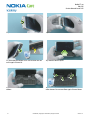
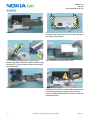
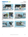
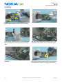
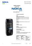
Nokia E7-00
RM-626
Service Manual Level 1&2
SERVICE MANUAL
Level 1&2
RM-626
Transceiver characteristics
Band
WCDMA 850/900/1800/1900/2100
EGSM 850/900/1700/1900
Display
4” AMOLED, up to 16 million colors, 16:9 widescreen
aspect ratio, 640x360 pixel resolution
Camera
8 Mpix Full Focus (EDOF) camera with dual led flash
Operating System
Symbian^3
Connections:
HDMI connector with Dolby Digital plus, analog TV out
with stereo audio via 3.5 mm AV connector, Micro USB
2.0 with OTG support, Bluetooth 2.1 + EDR and 3.0,
WLAN 802.11 b/g/n
Transceiver with BL-4D battery pack
Talk time
Standby
GSM:
Up to 9 hours
WCDMA:
Up to 5 hours
GSM:
Up to 430 hours
WCDMA:
Up to 470 hours
Note:
Talk times are dependent on network parameters
and phone settings
1
Confidential | Copyright © 2010 Nokia | All rights reserved
Version 1.0
Nokia E7-00
RM-626
Service Manual Level 1&2
Table of contents
1.
COPYRIGHT .......................................................................................................................................................................... 4
2.
WARNINGS AND CAUTIONS ............................................................................................................................................. 5
2.1
WARNINGS................................................................................................................................................................. 5
2.2
CAUTIONS................................................................................................................................................................... 5
3.
ESD PROTECTION ............................................................................................................................................................... 6
4.
CARE AND MAINTENANCE ................................................................................................................................................ 7
5.
BATTERY INFORMATION................................................................................................................................................... 8
6.
EXPLODED VIEW ................................................................................................................................................................. 9
7.
SERVICE DEVICES ................................................................................................................................................................ 11
8.
SOFTWARE UPDATE........................................................................................................................................................... 12
9.
DISASSEMBLY INSTRUCTIONS ......................................................................................................................................... 13
10. ASSEMBLY INSTRUCTIONS ............................................................................................................................................... 25
11. SOLDER COMPONENTS ...................................................................................................................................................... 38
2
Confidential | Copyright © 2010 Nokia | All rights reserved
Version 1.0
Nokia E7-00
RM-626
Service Manual Level 1&2
CHANGE HISTORY
Status
Version No.
Date
Comments
Approved
1.0
18.11.2010
First approved version
The purpose of this document is to help NOKIA service levels 1 and 2 workshop technicians to
carry out service to NOKIA products. This Service Manual is to be used only by authorized NOKIA
service suppliers, and the content of it is confidential. Please note that NOKIA provides also other
guidance documents (e.g. Service Bulletins) for service suppliers, follow these regularly and
comply with the given instructions.
While every endeavor has been made to ensure the accuracy of this document, some errors may
exist. If you find any errors or if you have further suggestions, please notify NOKIA using the
address below:
Nokia Care Academy
[email protected]
Please keep in mind also that this documentation is continuously being updated and modified,
so watch always out for the newest version.
3
Confidential | Copyright © 2010 Nokia | All rights reserved
Version 1.0
Nokia E7-00
RM-626
Service Manual Level 1&2
1. COPYRIGHT
Copyright © 2010 Nokia. All rights reserved.
Reproduction, transfer, distribution or storage of part or all of the contents in this document in
any form without the prior written permission of Nokia is prohibited.
Nokia, Nokia Connecting People, and Nokia X and Y are trademarks or registered trademarks of
Nokia Corporation. Other product and company names mentioned herein may be trademarks or
tradenames of their respective owners.
Nokia operates a policy of continuous development. Nokia reserves the right to make changes
and improvements to any of the products described in this document without prior notice.
Under no circumstances shall Nokia be responsible for any loss of data or income or any special,
incidental, consequential or indirect damages howsoever caused.
The contents of this document are provided “as is”. Except as required by applicable law, no
warranties of any kind, either express or implied, including, but not limited to, the implied
warranties of merchantability and fitness for a particular purpose, are made in relation to the
accuracy, reliability or contents of this document. Nokia reserves the right to revise this
document or withdraw it at any time without prior notice.
The availability of particular products may vary by region.
IMPORTANT
This document is intended for use by qualified service personnel only.
4
Confidential | Copyright © 2010 Nokia | All rights reserved
Version 1.0
Nokia E7-00
RM-626
Service Manual Level 1&2
2. WARNINGS AND CAUTIONS
Please refer to the phone’s user guide for instructions relating to operation, care and
maintenance including important safety information. Note also the following:
2.1 Warnings
1. CARE MUST BE TAKEN ON INSTALLATION IN VEHICLES FITTED WITH ELECTRONIC ENGINE
MANAGEMENT SYSTEMS AND ANTI–SKID BRAKING SYSTEMS. UNDER CERTAIN FAULT CONDITIONS,
EMITTED RF ENERGY CAN AFFECT THEIR OPERATION. IF NECESSARY, CONSULT THE VEHICLE
DEALER/MANUFACTURER TO DETERMINE THE IMMUNITY OF VEHICLE ELECTRONIC SYSTEMS TO RF
ENERGY.
2. THE HANDPORTABLE TELEPHONE MUST NOT BE OPERATED IN AREAS LIKELY TO CONTAIN
POTENTIALLY EXPLOSIVE ATMOSPHERES, EG PETROL STATIONS (SERVICE STATIONS), BLASTING
AREAS ETC.
3. OPERATION OF ANY RADIO TRANSMITTING EQUIPMENT, INCLUDING CELLULAR TELEPHONES, MAY
INTERFERE WITH THE FUNCTIONALITY OF INADEQUATELY PROTECTED MEDICAL DEVICES. CONSULT
A PHYSICIAN OR THE MANUFACTURER OF THE MEDICAL DEVICE IF YOU HAVE ANY QUESTIONS.
OTHER ELECTRONIC EQUIPMENT MAY ALSO BE SUBJECT TO INTERFERENCE.
2.2 Cautions
1. Servicing and alignment must be undertaken by qualified personnel only.
2.
Ensure all work is carried out at an anti–static workstation and that an anti–static wrist
strap is worn.
3. Use only approved components as specified in the parts list.
4. Ensure all components, modules screws and insulators are correctly re–fitted after servicing
and alignment.
5. Ensure all cables and wires are repositioned correctly
5
Confidential | Copyright © 2010 Nokia | All rights reserved
Version 1.0
Nokia E7-00
RM-626
Service Manual Level 1&2
3. ESD PROTECTION
Nokia requires that service points have sufficient ESD protection (against static
electricity) when servicing the phone.
Any product of which the covers are removed must be handled with ESD
protection. The SIM card can be replaced without ESD protection if the product
is otherwise ready for use.
To replace the covers ESD protection must be applied.
All electronic parts of the product are susceptible to ESD. Resistors, too, can be
damaged by static electricity discharge.
All ESD sensitive parts must be packed in metallized protective bags during
shipping and handling outside any ESD Protected Area (EPA).
Every repair action involving opening the product or handling the product
components must be done under ESD protection.
ESD protected spare part packages MUST NOT be opened/closed out of an ESD
Protected Area.
For more information and local requirements about ESD protection and ESD
Protected Area, contact your local Nokia After Market Services representative.
6
Confidential | Copyright © 2010 Nokia | All rights reserved
Version 1.0
Nokia E7-00
RM-626
Service Manual Level 1&2
4. CARE AND MAINTENANCE
This product is of superior design and craftsmanship and should be treated with care. The
suggestions below will help you to fulfil any warranty obligations and to enjoy this product for
many years.
•
Keep the phone and all its parts and accessories out of the reach of small
children.
•
Keep the phone dry. Precipitation, humidity and all types of liquids or
moisture can contain minerals that will corrode electronic circuits.
•
Do not use or store the phone in dusty, dirty areas. Its moving parts can be
damaged.
•
Do not store the phone in hot areas. High temperatures can shorten the life
of electronic devices, damage batteries, and warp or melt certain plastics.
•
Do not store the phone in cold areas. When it warms up (to its normal
temperature), moisture can form inside, which may damage electronic circuit
boards.
•
Do not drop, knock or shake the phone. Rough handling can break internal
circuit boards.
•
Do not use harsh chemicals, cleaning solvents, or strong detergents to clean
the phone.
•
Do not paint the phone. Paint can clog the moving parts and prevent proper
operation.
•
Use only the supplied or an approved replacement antenna. Unauthorised
antennas, modifications or attachments could damage the phone and may
violate regulations governing radio devices.
All of the above suggestions apply equally to the product, battery, charger or any accessory.
7
Confidential | Copyright © 2010 Nokia | All rights reserved
Version 1.0
Nokia E7-00
RM-626
Service Manual Level 1&2
5. BATTERY INFORMATION
Note: A new battery’s full performance is achieved only after two or three complete charge and
discharge cycles! The battery can be charged and discharged hundreds of times but it will
eventually wear out.
When the operating time (talk-time and standby time) is noticeably shorter than normal, it is
time to buy a new battery. Use only batteries approved by the phone manufacturer and
recharge the battery only with the chargers approved by the manufacturer.
Unplug the charger when not in use. Do not leave the battery connected to a charger for longer
than a week, since overcharging may shorten its lifetime.
If left unused a fully charged battery will discharge itself over time Temperature extremes can
affect the ability of your battery to charge.
For good operation times with Ni-Cd/NiMh batteries, discharge the battery from time to time by
leaving the product switched on until it turns itself off (or by using the battery discharge facility
of any approved accessory available for the product).
Do not attempt to discharge the battery by any other means Use the battery only for its
intended purpose.
Never use any charger or battery which is damaged.
Do not short-circuit the battery. Accidental short-circuiting can occur when a metallic object
(coin, clip or pen) causes direct connection of the + and - terminals of the battery (metal strips
on the battery) for example when you carry a spare battery in your pocket or purse.
Shortcircuiting the terminals may damage the battery or the connecting object.
Leaving the battery in hot or cold places, such as in a closed car in summer or winter conditions,
will reduce the capacity and lifetime of the battery. Always try to keep the battery between 15°C
and 25°C (59°F and 77°F).
A phone with a hot or cold battery may temporarily not work, even when the battery is fully
charged. Batteries’ performance is particularly limited in temperatures well below freezing.
Do not dispose batteries in a fire! Dispose of batteries according to local regulations (e.g.
recycling).
Do not dispose as household waste.
8
Confidential | Copyright © 2010 Nokia | All rights reserved
Version 1.0
Nokia E7-00
RM-626
Service Manual Level 1&2
6. EXPLODED VIEW
LID FRAME
I0004
WINDOW
I0005
DISPLAY
I0007
EARPIECE
I0006
A1
CHASSIS ASSEMBLY
(A2, A3, I0217 - I0221)
L3
LID CHASSIS ASSEMBLY
(I0101 - I0103)
A2
SPACER FLEX LID
I0101
UI FLEX
I0102
LID CHASSIS
I0103
HINGE ELEMENT
I0217
HINGE ELEMENT
AUXILIARY SHAFT
I0218
HINGE PIN
I0219
SCREW TORX+ SIZE 4
M1.4x3.8
I0221
HINGE COVER
I0220
SCREW TORX+ SIZE 4
M1.6x2.5
I0008
SCREW TORX+ SIZE 4
M1.0x1.9
I0009
SCREW TORX+ SIZE 4
M1.4x5.6
I0201
SCREW PHILLIPS
SIZE 00 M1.4x2.3
I0202
A4
L3
QWERTY KEYMAT
I0203
TYPE LABEL
I0223
BOTTOM END DECO
I0238
SCREW TORX+ SIZE 4
M1.4x3.0
I0237
BOTTOM END CAP
I0236
CONNECTOR LOCK PLATE
I0204
TOP END DECO
I0001
SCREW TORX+ SIZE 4
RF1.4x3.0
I0002
Ver. 1.0
9
Page 1/2
TOP END CAP
I0003
Only available
as assembly
Confidential | Copyright © 2010 Nokia | All rights reserved
Not reuseable
after removal
L3 Repair/swap
only in level 3
Version 1.0
Nokia E7-00
RM-626
Service Manual Level 1&2
CHASSIS ASSEMBLY
A3 BASE
(I0205 - I0216)
MICROPHONE
I0214
BASE CHASSIS
I0216
ANTENNA PWB
I0215
QWERTY
FLEX MODULE
I0206
KEYMAT
DOMESHEET
I0205
COAX CABLE BLACK
I0209
AV JACK
I0207
POWER KEY
I0208
A4
COAX CABLE WHITE
I0210
LIGHT SWAP PACKAGE
(I0222 - I0223) L3
WASHER
I0212
SCREW PHILLIPS
SIZE 00 M1.4x2.3
I0211
LIGHT SWAP PWB
I0222
CABLE COVER
I0213
CAMERA MODULE
I0224
FRAME ASSEMBLY
A5 PWB
(I0225 - I0227)
ANTENNA FRAME ASSEMBLY
(I0229 - I0231)
A6
IHF SPEAKER
I0229
ANTENNA FRAME
I0231
IHF ADHESIVE
I0230
GPS ANTENNA
I0225
PWB FRAME
I0227
WLAN/BT ANTENNA
I0226
SCREW TORX+ SIZE 4
M1.4x3.9
I0228
BATTERY BL-4D
I0232
SIM HOLDER
I0235
BACK COVER
I0233
SCREW TORX+ SIZE 4
M1.4x3.9
I0234
Ver. 1.0
10
Page 2/2
Only available
as assembly
Confidential | Copyright © 2010 Nokia | All rights reserved
Not reuseable
after removal
L3 Repair/swap
only in level 3
Version 1.0
Nokia E7-00
RM-626
Service Manual Level 1&2
7. SERVICE DEVICES
FLS-5 Flash Device
BL-4D Battery
AC-10 Travel Charger
CA-101 Service Cable
SS-210 Camera Removal tool
Nokia Standard Toolkit (v2)
For more information, refer to the
Service Bulletin (SB-011) on Nokia
Online. Supplier or manufacturer
contacts for tool re-order can be
found in “Recommended service
equipment” document on Nokia
Online.
SS-231 RF Connector tool
11
Confidential | Copyright © 2010 Nokia | All rights reserved
Version 1.0
Nokia E7-00
RM-626
Service Manual Level 1&2
8. SOFTWARE UPDATE
Flash concept (Point of Sale)
To use the FLS-5 Flash Dongle, follow the user guide inside the sales package. Please check
always for the latest version of flash software, which is available on Nokia Online.
12
Confidential | Copyright © 2010 Nokia | All rights reserved
Version 1.0
Nokia E7-00
RM-626
Service Manual Level 1&2
9. DISASSEMBLY INSTRUCTIONS
1) Nokia E7-00 disassembly.
2) You must use the Nokia Standard Toolkit version
2. You will also need the SS-231 RF Connector tool,
SS-210 Camera Removal tool and an AV plug.
3) Protect the WINDOW with protective film.
4) Pull out the SIM HOLDER with the SRT-6 and
remove it.
5) Open the HDMI door.
6) Use the SRT-6 to release the TOP END DECO as
shown.
13
Confidential | Copyright © 2010 Nokia | All rights reserved
Version 1.0
Nokia E7-00
RM-626
Service Manual Level 1&2
7) The TOP END DECO is not reusable. Discard it.
8) Unscrew the two Torx+ size 4 screws in the order
shown.
9) Release the TOP END CAP by pushing it to the
direction shown.
10) Remove the TOP END CAP.
11) To release the BOTTOM END DECO, slide the SRT-6
under it to the direction shown.
12) Remove the BOTTOM END DECO.
14
Confidential | Copyright © 2010 Nokia | All rights reserved
Version 1.0
Nokia E7-00
RM-626
Service Manual Level 1&2
13) Unscrew the shown Torx+ size 4 screw.
14) Pull out and remove the BOTTOM END CAP.
15) Unscrew the shown Torx+ size 4 screw. Do not
use it again. Discard it.
16) Slide the device open.
17) Then turn the display part of the device as
shown.
18) Unscrew the four Phillips size 00 screws in the
order shown. Do not use them again. Discard them.
15
Confidential | Copyright © 2010 Nokia | All rights reserved
Version 1.0
Nokia E7-00
RM-626
Service Manual Level 1&2
19) Remove the QWERTY KEYMAT.
20) Close the device and unscrew the four Torx+ size
4 screws in the order shown. These screws cannot be
used again. Discard them.
21) To release the BACK COVER, insert the SRT-6
between the BACK COVER and the BASE CHASSIS. Then
slide the SRT-6 to the direction shown. Do this ONLY
on LOCK KEY side!
22) Lift up and remove the BACK COVER.
23) Lift up the BATTERY with the SRT-6 and remove it. 24) Open the device as shown. Release the
CONNECTOR LOCK PLATE carefully with the dental tool.
Be careful not to injure yourself or the connector
under the CONNECTOR LOCK PLATE with the sharp end
of the dental tool!
16
Confidential | Copyright © 2010 Nokia | All rights reserved
Version 1.0
Nokia E7-00
RM-626
Service Manual Level 1&2
25) Remove the CONNECTOR LOCK PLATE with the
tweezers. The CONNECTOR LOCK PLATE cannot be
reused. Discard it.
26) Open the QWERTY FLEX MODULE connector with
the dental tool. Be careful not to damage the
connector or any nearby components!
27) Close the device. Open the three shown clips
holding the ANTENNA FRAME ASSEMBLY by using the
SRT-6.
28) The ANTENNA FRAME ASSEMBLY can be now
separated.
29) Use the dental tool to lever out the IHF SPEAKER.
Remove the IHF SPEAKER with the tweezers.
30) Unscrew the two Torx+ size 4 screws in the order
shown. Do not use them again. Discard them.
17
Confidential | Copyright © 2010 Nokia | All rights reserved
Version 1.0
Nokia E7-00
RM-626
Service Manual Level 1&2
31) Open the three shown clips holding the ENGINE
BOARD FRAME ASSEMBLY with the SRT-6 as shown.
32) Remove the ENGINE BOARD FRAME ASSEMBLY.
33) Use the RF connector tool SS-231 to release the
two coax cables. First place the tool on top of the
cable.
34) Then slide it to direction shown to lock it to the
connector. Pull up the SS-231 to release the cable.
35) Use the same procedure on the second cable
connector.
36) Turn the ENGINE BOARD carefully around. Open
the UI FLEX connector with the SRT-6. Be careful not
to damage the connector or nearby components!
18
Confidential | Copyright © 2010 Nokia | All rights reserved
Version 1.0
Nokia E7-00
RM-626
Service Manual Level 1&2
37) The ENGINE BOARD can now be separated.
38) Use the camera removal tool SS-210 to release
the CAMERA MODULE. Lift up and remove the CAMERA
MODULE.
39) Remove the CABLE COVER.
40) Unscrew the shown Phillips size 00 screw. This
screw cannot be reused. Discard it.
41) Remove also the WASHER with the tweezers.
42) Use the SS-231 to release the other end of the
BLACK COAX CABLE.
19
Confidential | Copyright © 2010 Nokia | All rights reserved
Version 1.0
Nokia E7-00
RM-626
Service Manual Level 1&2
43) Remove the BLACK COAX CABLE with the
tweezers.
44) Release also the WHITE COAX CABLE connector
with the SS-231. Remove it with the tweezers.
45) Use the AV plug to lift up and release the AV JACK.
Discard the AV JACK.
46) Use the tweezers to lift up and remove the
POWER KEY.
47) Open up the device as shown and unscrew the
four Torx+ size 4 screws in the order shown. Do not
use them again. Discard them.
48) Turn the BASE CHASSIS ASSEMBLY to the other
side as shown and unscrew the four Torx+ size 4
screws in the order shown. Do not use them again.
Discard them.
20
Confidential | Copyright © 2010 Nokia | All rights reserved
Version 1.0
Nokia E7-00
RM-626
Service Manual Level 1&2
49) Close the device. Release the LID FRAME by lifting
up from one of its corners.
50) Then release all the other sides and remove the
LID FRAME.
51) Release the clip holding the WINDOW with the
DENTAL TOOL.
52) Release also the second clip on the opposite side.
53) Lift up the WINDOW very carefully with the SRT-6
from both sides. Be careful not to damage the
WINDOW flex! Note that only the WINDOW has to be
lifted. The DISPLAY should remain on its place.
54) Turn around the WINDOW. While turning the
WINDOW, be careful not to damage the WINDOW
flex.
21
Confidential | Copyright © 2010 Nokia | All rights reserved
Version 1.0
Nokia E7-00
RM-626
Service Manual Level 1&2
55) Protect the DISPLAY with protective film.
56) Lift up the DISPLAY and turn it around. While
turning the DISPLAY, be careful not to damage the
DISPLAY flex.
57) Open the DISPLAY connector with the SS-93. Be
careful not to damage the connector!
58) Remove the DISPLAY.
59) Protect the other side of the WINDOW with
protective film.
60) Use the SRT-6 to release the SPACER FLEX LID. Be
careful not to damage the components nearby!
22
Confidential | Copyright © 2010 Nokia | All rights reserved
Version 1.0
Nokia E7-00
RM-626
Service Manual Level 1&2
61) Remove the SPACER FLEX LID with the tweezers.
Do not use it again. Discard it.
62) Open the WINDOW connector with the SRT-6. Be
careful not to damage the connector.
63) Release the shown part of the WINDOW flex with
the dental tool. Be very careful not to damage the
flex while releasing it.
64) The WINDOW can now be separated.
65) Release the EARPIECE with the SRT-6.
66) Remove the EARPIECE with the tweezers. Do not
use the EARPIECE again. Discard it.
23
Confidential | Copyright © 2010 Nokia | All rights reserved
Version 1.0
Nokia E7-00
RM-626
Service Manual Level 1&2
67) The Nokia E7-00 disassembly is now complete.
-END OF DISASSEMBLY-
24
Confidential | Copyright © 2010 Nokia | All rights reserved
Version 1.0
Nokia E7-00
RM-626
Service Manual Level 1&2
10. ASSEMBLY INSTRUCTIONS
1) Nokia E7-00 assembly.
2) You must use the Nokia Standard Toolkit version
2. You will also need the SS-231 RF Connector tool.
3) Place the POWER KEY with the tweezers.
4) Place the AV JACK with the tweezers, and push it
with the SS-93 as shown to lock it in its place.
5) Slide the SS-231 to direction shown to lock it to
the BLACK COAX CABLE connector.
6) Push the connector to its place with the SS-231.
Make sure BLACK COAX CABLE is connected to the
shown connector.
25
Confidential | Copyright © 2010 Nokia | All rights reserved
Version 1.0
Nokia E7-00
RM-626
Service Manual Level 1&2
7) Carefully bend the BLACK COAX CABLE to its place as 8) To connect the WHITE COAX CABLE, use the same
shown. Make sure that the metal shell of the cable is procedure as with the BLACK COAX CABLE.
placed in the shown place.
9) Carefully bend the WHITE COAX CABLE to its place
as shown. Make also sure that the metal shell of the
WHITE COAX CABLE is in the shown place.
10) Place the WASHER to its place with the tweezers.
11) Tighten the Phillips size 00 screw to the torque
of 10 Ncm.
12) Push the CABLE COVER to its place. Make sure that
cables are inside the CABLE COVER.
26
Confidential | Copyright © 2010 Nokia | All rights reserved
Version 1.0
Nokia E7-00
RM-626
Service Manual Level 1&2
13) Open up the EARPIECE package. Remove the
EARPIECE protective film.
14) Use the shown guiding markings on the
WINDOW to place the EARPIECE with the tweezers
and push it down with the SS-93 to activate the
adhesive.
15) Remove the WINDOW flex adhesive protective
film.
16) Connect the WINDOW connector by gently
pressing it with the SS-93. Be careful not to damage
the connector or any nearby components.
17) Attach the WINDOW flex adhesive by gently
pressing with the SS-93. Be careful not to damage
the connector or any nearby components.
18) Remove the SPACER FLEX LID adhesive protective
film.
27
Confidential | Copyright © 2010 Nokia | All rights reserved
Version 1.0
Nokia E7-00
RM-626
Service Manual Level 1&2
19) Place the SPACER FLEX LID by using the two
shown guiding pins. Activate the SPACER FLEX LID
adhesive by carefully pressing it with the SS-93.
20) Connect the DISPLAY connector with the SS-93.
Be careful not to damage any nearby components.
21) Turn around the DISPLAY. Be careful not to
damage the DISPLAY flex while turning the DISPLAY.
22) Press the DISPLAY flex to bend it as shown.
23) Remove the DISPLAY protective film.
24) Remove the protective film from the inner side of
the WINDOW.
28
Confidential | Copyright © 2010 Nokia | All rights reserved
Version 1.0
Nokia E7-00
RM-626
Service Manual Level 1&2
25) Turn the WINDOW over. While turning the
WINDOW, make sure that the WINDOW connector
stays connected and the WINDOW flex remains
undamaged.
26) Press from side of the device as shown, to lock
the shown clip holding the WINDOW in the LID
CHASSIS ASSEMBLY.
27) Press also from the other side of the device as
shown, to lock the shown clip holding the WINDOW
in the LID CHASSIS ASSEMBLY.
28) Place the LID FRAME onto the WINDOW and press
from all sides of the LID FRAME to attach it to the LID
CHASSIS ASSEMBLY.
29) Slide open the device. Tighten these two TORX +
size 4 screws to the torque of 5 Ncm in the order
shown.
30) Tighten these two TORX + size 4 screws to the
torque of 12 Ncm in the order shown.
29
Confidential | Copyright © 2010 Nokia | All rights reserved
Version 1.0
Nokia E7-00
RM-626
Service Manual Level 1&2
31) Remove the protective film.
32) Pull out and remove the HINGE PIN to release the
BASE CHASSIS ASSEMBLY.
33) Tighten these two TORX + size 4 screws to the
torque of 5 Ncm in the order shown.
34) Tighten these two TORX + size 4 screws to the
torque of 12 Ncm in the order shown.
35) Remove the DUMMY KEYMAT with the tweezers
and close the device.
36) Move the two coaxial cables to the side, so that
they are not damaged while assembling the ENGINE
BOARD.
30
Confidential | Copyright © 2010 Nokia | All rights reserved
Version 1.0
Nokia E7-00
RM-626
Service Manual Level 1&2
37) Connect the UI FLEX connector. Be careful not to
damage connector or any nearby components.
38) Lower down the ENGINE BOARD and check that
the guiding pin is aligned correctly.
39) Check also the second guiding pin on the other
side of the engine board.
40) Use the SS-231 and the same procedure as
before to connect the BLACK COAX CABLE connector to
the connector marked with a letter B.
41) Use the SS-231 to connect the WHITE COAX CABLE
connector to the connector marked with a letter W.
42) Place the ENGINE BOARD FRAME ASSEMBLY onto
the ENGINE BOARD. Press from the shown places to
lock it to its place.
31
Confidential | Copyright © 2010 Nokia | All rights reserved
Version 1.0
Nokia E7-00
RM-626
Service Manual Level 1&2
43) Finally press from shown place to lock the
remaining holder. Make sure that the cables are not
damaged while attaching the ENGINE BOARD FRAME
ASSEMBLY.
44) Place the ANTENNA FRAME ASSEMBLY as shown.
Press the ANTENNA FRAME ASSEMBLY to lock the
shown three clips. Be aware not to press from the
IHF ADHESIVE area marked with red rectangle.
45) Tighten the two TORX + size 4 screws to the
torque of 12 Ncm in the order shown.
46) Place the CAMERA MODULE with the tweezers as
shown. Make sure the CAMERA MODULE guiding is
aligned with the guiding in the camera gasket.
47) Press gently the CAMERA MODULE with the SS-93
to attach the camera retaining clips.
48) Open up the device. Connect the QWERTY
connector with the SS-93. Be careful not to damage
the connector.
32
Confidential | Copyright © 2010 Nokia | All rights reserved
Version 1.0
Nokia E7-00
RM-626
Service Manual Level 1&2
49) Place the CONNECTOR LOCK PLATE to its place.
Press the CONNECTOR LOCK PLATE with the SS-93 to
attach the two clips holding it.
50) Close the device and insert the BATTERY to its
place.
51) Remove the camera window protective film from
the inner side of the BACK COVER.
52) Insert the shown side of the BACK COVER into
BASE CHASSIS ASSEMBLY.
53) Then press from the opposite side to lock the
BACK COVER to the BASE CHASSIS ASSEMBLY.
54) Tighten the four TORX + size 4 screws to the
torque of 14 Ncm in the order shown.
33
Confidential | Copyright © 2010 Nokia | All rights reserved
Version 1.0
Nokia E7-00
RM-626
Service Manual Level 1&2
55) Slide open the device. Slide the QWERTY KEYMAT
edge under the BACK COVER EDGE as shown.
56) Tighten the four Phillips size 00 screws to the
torque of 8 Ncm in the order shown.
57) Close the device. Push the BOTTOM END CAP into
its place and make sure that both sides are correctly
placed and there is no gap visible.
58) Tighten the TORX + size 4 screw to the torque of
10 Ncm.
59) Take new BOTTOM END DECO.
60) Attach the BOTTOM END DECO onto the BOTTOM
END CAP as shown. Press the BOTTOM END DECO to
activate the adhesive.
34
Confidential | Copyright © 2010 Nokia | All rights reserved
Version 1.0
Nokia E7-00
RM-626
Service Manual Level 1&2
61) Tighten the TORX + size 4 screw to the torque of
10 Ncm.
62) Remove the protective film from the TOP END
CAP.
63) Open the HDMI door.
64) Push the TOP END CAP into its place as shown.
Make sure the TOP END CAP is correctly in its place
and there are no gaps visible.
65) Tighten the two TORX + size 4 screws to the
torque of 10 Ncm in the order shown.
66) Close the HDMI door.
35
Confidential | Copyright © 2010 Nokia | All rights reserved
Version 1.0
Nokia E7-00
RM-626
Service Manual Level 1&2
67) Remove the protective film from TOP END DECO.
68) Remove the protective film also from the other
side.
69) Place the TOP END DECO as shown. Push the TOP
END DECO to lock it into its place.
70) Remove the volume key protective film.
71) Push in the SIM HOLDER.
72) Test that the volume key is working by pushing it
in both directions few times.
36
Confidential | Copyright © 2010 Nokia | All rights reserved
Version 1.0
Nokia E7-00
RM-626
Service Manual Level 1&2
73) Remove the protective film from the back cover.
74) Remove the lock key protective film.
75) Test that the lock key is working by pushing it
few times.
76) Now the Nokia E7-00 assembly procedure is
complete.
-END OF ASSEMBLY-
37
Confidential | Copyright © 2010 Nokia | All rights reserved
Version 1.0
Nokia E7-00
RM-626
Service Manual Level 1&2
11. SOLDER COMPONENTS
TOP
S2402
X2701
X2702
X2400
X1650
V2505
V2506
F3300
BOTTOM
X6705
X1502
X6700
X1500
V1500
X6704
X6703
X7403
X7402
Ver. 1.0
38
Confidential | Copyright © 2010 Nokia | All rights reserved
Version 1.0