1
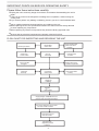
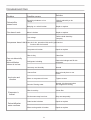
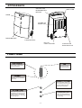
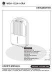
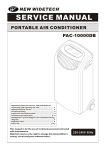
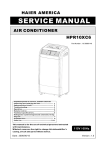
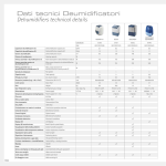
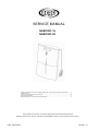
SERVICE MANUAL
NARCISO 16
NARCISO 20
Important points on service, and operating safety, with a flow-chart for inspection and repair...........1
Troubleshooting …………………………………………………………..................................................2
Appearance and and functions of this unit ......................................................................................3
Technical specifications ……………………………………………………….................... .. ...............4
Refrigerator system and schematic wiring Diagrams ………………................................................. ..5
This manual is for the use of technical personnel entrusted with maintenance.
Widetech reserves the right to change this dehumidifier's casing, circuit and parts without notice.
Date: 2009/09/15
Version: 1.0
IMPORTANT POINTS ON SERVICE OPERATING SAFETY
Please follow these instructions carefully:
Unplug the unit to avoid any danger from electric shock before disassembling the unit for
repair.
If there is any sound of the refrigerant circulating when in operation, avoid touching the
cooling coils.
If you need to perform any welding or soldering, be sure you are in a well ventilated area.
Only a qualified professional should perform any welding on the unit.
When repairing the unit, the specifications listed in this manual must be strictly adhered
to when replacing any components.
When replacing any electrical components they should be factory approved units.
Be sure that any electrical components are properly wired and in place.
FLOW CHART FOR INSPECTING AND REPAIRING THE UNIT
Electricity shutdown
Check fuses
on main switch
Dehumidifier
doesn't work
Check if drain bucket
water level switch
is broken
Can not
dehumidify
Humidity switch
is broken
Humidity switch is set
on continuous operation
Check if air filter
is clogged
Capacitors
are faulty
Compressor
doesn't work
Refrigerant
is leaking
Maintain
&
repair system
Supply Nitrogen 15KG/CM2 from low
pressure side and locate the leakage
Use oxygen acetylene and 5% silver
iron to fill cracks and holes
Pump vacuum for at
least 15 minutes
After filling with
refrigerant proceed
to test run
- 1-
Over load protector
is faulty
TROUBLESHOOTING
Problem
Dehumidifier
doesn't work
Fan doesn't work
Possible causes
Solution
Electricity shutdown or low
voltage
Wait for electricity to be
restored
Bad plug or a wire is broken
Repair or replace
Motor is broken
Repair or replace
Low voltage
Call the local electricity
company
Compressor doesn't Still under the 3 min. protection Wait until if goes back to
function after 3 min.work
Can not dehumidify
or the
dehumidifcation
volume is too low
Loud noise and
vibration
Evaporator is
frosted
Compressor is broken
Repair or replace
Filter is dirty
Clean filter
Refrigerant is leaking
Detect the leakage and fill with
refrigerant.
Low temp. and humidity
Normal
Uneven floor
Move to level place or use
blocks
Motor or compressor is loose
Tighten screws
Sound of flowing water
Normal, it is the sound when
the refrigerant is flowing
Filter is too dirty
Clean filter
Environment temp.is too low
Stop use temporarily
Drain bucket is broken
Repair or replace
Minor-moving switch is broken
Repair or replace
Dehumidification
water overflows
-2-
APPEARANCE
OUTLET FOR
DEHUMIDIFIED
DRY AIR
AIR FILTER
KNOB
INTANK OF
MOIST AIR
DRAIN BUCKET
TURNING WHEEL
BUILT-IN
CABLE STORAGE
CONTINUOUS
DRAINAGE HOLE
FUNCTIONS
CONTINUOUS
OFF
Dehumidifier continuously
removing moisture.
Dehumidifier stop
removing moisture.
NORMAL
Humidity control between
50%-60%.
BUCKET FULL LAMP
When the water tank is full
the full tank lamp will light up,
the dehumidifier will stop
operating immediately.
DEFROST LAMP
RUNNING LAMP
When operating under low
temperature for a short period,
the dehumidifier will starting
defrost process, the indicating
lamp will light up.
When the lamp lights up
which means dehumidifier
is operating.
-3-
TECHNICAL SPECIFICATIONS
DEHUMIDIFIER
ITEM
NARCISO 16-20
UNIT
16
20
DEHUMIDIFYING CAPACITY
L/day (30°C-80% R.H.)
POWER SOURCE
V/Hz
220-240V 50Hz
NOISE
dB(A)
42
POWER CONSUMPTION
W
CURRENT
A
320
1.39
PHP-206.16A 250V、H 0 5 VV - F 3 G 0 .75 mm 2
WIRE SPECIFICATION
DIMENSIONS
mm
4 05W x63 2Hx2 90D
NET
kg
13,8 /
35D0 26- A1- AKDA
MODEL NUMBER
COMPRESSOR
POWERASS'Y
CONSUMPTION
34 1
W
LS-1 6D1 -01
MODEL NUMBER
FAN MOTOR
14
POWER
CONSUMPTION
HEAT EVAPORATOR
EXCHANGER
UNIT CONDENSER
REFRIGERANT
CAPILLARY TUBE
30
W
RxSxFPIxW
1R 8S19 FPI x12 .7mm
RxSxFPIxW
2 R8S 19F PIx 25. 4mm
R-410A/g
1 60
D2.1x d0. 9x8 00
mm
COMP O.L.P
DRAIN BUCKET CAPACITY
M RA12 263 -120 95
3. 5
L
-4-
REFRIGERATOR SYSTEM DIAGRAM
CAPILLARY TUBE
DRYER
PTC(HEATER)
EVAPORATOR
CONDENSER
FAN MOTOR
COMPRESSOR ASS'Y
FUSE
T6.3AL 250V
BROWN
SCHEMATI C WIRING DIAGRAM
CMP
FAN
MOTOR
WHITE
BLACK
AC CORD
RUN LAMP
BLUE
WHITE
CAPACITOR
FULL LAMP
DEFROST
LAMP
SENSOR
HUMIDITY SWITCH
BLUE
D6951-630
-5-