1
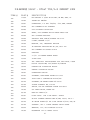
SERIES LT7000
LIGHT TOWER
OPERATION/SERVICE
& PARTS MANUAL
PO Box 3147 • Rock Hill, SC 29732 USA Phone
•
803-324-3011
Toll Free 800-433-3026
Parts Department Fax 800-633-5534
THIS MANUAL HAS BEEN SPECIFICALLY PREPARED FOR THE FOLLOWING
LIGHT TO W E R
TLC Model Number
Serial Number
_______________
Engine Model Number ______________
Serial Number
_______________
Generator Model Number ______________
Serial Number
_______________
Sold To:
_________________________
Ship To:
_________________________
______________________________
_________________________
Production Date: ____/_____/_____
_________________________
W ork Order Number: ___________
_________________________
Shipping Date: _____/_____/_____
_________________________
In Service Date: _____/_____/_____
Options:
_______________
____________________
_________________________
When this unit left the factory the engine was filled with engine oil of grade:_________
This Operation & Service Manual contains information specifically pertaining to the operating and
maintenance of this TEREX Light Construction Tower. W e suggest that you read this manual carefully
prior to operating the Light Tower. This manual should be retained and referred to for operation, maintenance, and ordering parts. When ordering parts, PLEASE INCLUDE THE MODEL AND SERIAL
NUMBER located on the nameplate of the Light Tower.
For major repair and service or other information, contact your TEREX Light Construction dealer or
call or write:
TEREX Light Construction
P.O. Box 3147 (29732)
590 Huey Road
Rock Hill, SC 29730
Telephone: (803) 324-3011
FAX: (803) 366-1101
When returning parts for credit, please contact the factory for Return of Goods Authorization.
2
TABLE OF CONTENTS
W ARNING!!!
READ OPERATING,TROUBLESHOOTING,A N D
CAUTION!!!! MAINTENANCE INSTRUCTIONS CAREFULLY BEFORE
OPERATING THIS PIECE OF EQUIPMENT.
O P E R ATING INSTRUCTIONS AND MAINTENACE
Safety Precautions
Initial Set Up
Model Coding System
Operating Instructions
Oil & Fuel Specifications
Engine (See manufacturer’s handbook)
Generator (See manufacturer’s handbook)
Page 5-6
Page 7
Page 8
Page 9-13
Page 14-15
PA RTS DRAWINGS AND LISTS
9055
9109B
9366
9062A
9063A
9065C
9365
N/A
9069
9070B
9071
9072
9073
9074A
9123A
9075
9076
9528
9089
N/A
Axle w/wheels
Air Chamber – For unit with Lister Engine
Air Chamber – For unit with LPA3
Crossarm w/wiring 4 lights
Crossarm w/wiring 6 lights
Engine & Generator – Lister TS2 – Leroy Somer 8 KW
Engine & Generator – Lister LAP3 – Leroy Somer 7.5 KW
Engine & Generator – Kubota 1105– Leroy Somer 8 KW
Trailer Frame and Parts
Generator Enclosure
Tower and Base Assembly
Pivot Cylinder
Telescoping Cylinder
Hydraulic Piping
Electrical
CDC Control Box – For unit with Lister Engine
CDC Control Box – For unit with Kubota or Lister
CDC Control Box – For unit with Lister/Alpha
Hitches for trailers
Ballast
Fixture Assembly
3
Page 17
Page 18-19
Page 20-21
Page 22-23
Page 24-25
Page 26-27
Page 28
Page 29
Page 30-31
Page 32-33
Page 34-35
Page 36-37
Page 38-39
Page 40-41
Page 42-43
Page 44-45
Page 46-47
Page 48-49
Page 50
Page 51
Page 52
ELECTRICAL DRAW I N G S
2985A
2986
2987
2891
4730E
2641
2582
3612
3883
2640B
Fixture Schematic
Page 52
Metal Halide Ballast W iring Diagram
Page 54
High Pressure Sodium Ballast W iring Diagram
Page 55
Lister TS-2 Engine W iring
Page 56
Kubota Engine W iring
Page 57
Engine W iring Diagrams for Lister TS2 with CDC Panel Page 58
CDC Control Box W iring Diagram 4 MH for Kubota or Lister
Page 59
Control Box W iring Diagram with Kubota or Lister engine Page 60
Alpha Engine
Page 61
Lister Engine W iring Diagram with CDC Panel
Page 62
TROUBLESHOOTING AND MAINTENANCE
Tower Seal Replacement
Generator (Refer to manufacturer’s handbook)
Engine (Refer to manufacturer’s handbook)
Hydraulic Tower
Electrical
Traceable W iring
Generator Bearing Inspection
Page 63-65
Page 66-67
Page 68-71
Page 72
Page 73
W ARRANTY
Procedure
Terex Policy
Engine Manufacturer’s Policy (Refer to manufacturer’s handbook)
Generator Manufacturer’s Policy (Refer to manufacturer’s handbook)
Cards (Must be filled out and returned to validate warranty.
)
SAFETY
PRECAUTIONS
4
Page 74
Page 75
The following symbols in this manual signal potentially dangerous conditions to the
operator or equipment. Read This Manual Carefully. Know when these conditions
exist. Then take necessary steps to protect personnel, as well as equipment.
“ WARNING”
This Symbol Refers To Possible Serious Personal Injury.
CAUTION
This Symbol Refers to Possible Equipment Damage.
Lamps, Electrical Equipment, Fuel, Batteries, Exhaust Gases and moving parts present
potential hazards that could result in serious personal injury.Take care in following
these recommended procedures.
USE CAUTION W O R K I N G NEAR LAMPS
Metal halide lamps produce short wave ultra-violet radiation and can cause serious skin
burn and eye inflammation if the outer envelope of the lamp is broken or punctured. Do
not use where people will remain for more than a few minutes unless adequate shielding
or other safety precautions are used.
GUARD AGAINST ELECTRIC SHOCK
Disconnect or shutdown electric power before removing protective covers or touching
electrical equipment. Use rubber insulating mats placed on dry wood platforms over
floors that are metal or concrete when around electrical equipment. Do not wear damp
clothing (Particularly wet shoes) or allow skin surfaces to be damp when handling
electrical equipment.
USE EXTREME CAUTION NEAR GASOLINE AND DIESEL FUEL. A CONSTA N T
POTENTIAL EXPLOSIVE OR FIRE HAZARD EXIST.
Do not fill fuel tank with engine running. Do not smoke or use open flame near the unit
or the fuel tank. Be sure all fuel supplies have a positive shutoff
.
Have a fire extinguisher nearby. Be sure extinguisher is properly maintained and be
familiar with its proper
DO NOT SMOKE WHILE SERVICING BATTERIES
Lead acid batteries emit a highly explosive hydrogen gas that can be ignited by
electrical arcing or by smoking.
E X H A U S T GASES ARE TOXIC
Provide an adequate exhaust system to properly expel discharged gases. Check
5
exhaust system regularly for leaks. Ensure that exhaust manifolds are secure and not
warped. Be sure the unit is well ventilated.
K E E P THE UNIT AND SURROUNDING A R E A CLEAN
Remove all unnecessary grease and oil from unit. Accumulated grease and oil can
cause overheating and subsequent engine damage and may present a potential fire
hazard. Dispose of oily rags. Keep the floor of the unit clean and dry.
P R O T E C T AGAINST MOVING PA RTS
Avoid moving parts of the unit. Loose jackets, shirts, or sleeves should not be
permitted because of the danger of becoming caught in moving parts.
Make sure all nuts and bolts are secure. Keep power shields and guards in position.
If adjustments must be made while equipment is running, use extreme caution around
hot manifolds, moving parts, etc. Do not work on this equipment when mentally
or physically fatigued.
TEREX LIGHT CONSTRUCTION
CHECK OUT ON RECEIPT
OF DELIVERY:
6
The tower will be serviced, tested and ready for operation when received except for
export units which are knocked down and shipped with dry batteries. Terex recommends the following checks:
A. ENSURE THERE IS NO FREIGHT HANDLING DAMAGE which should be
charged against the carrier.
B. Ensure the manuals are in the pocket provided inside the unit.
C. Review the manuals for safety and operating procedures.
D. Check the engine oil, coolant (if liquid cooled) and fuel levels.
E. Operate tower in accordance with operating instructions.
EXPORT: Assemble according to assembly instructions enclosed.
Operation & Maintenance; Series LT7000
7
LIGHT TO W E R M O D E L CODING SYSTEM
I M P O RTA N T
WHEN REQUESTING TECHNICAL HELP AND ORDERING REPLACEMENT PA RTS THE MODEL A N D
SERIAL NUMBER ARE NECESSARY
REFER TO THE AMIDA SERIAL NUMBER TAG ON THE UNIT FOR CORRECT MODEL NUMBER A N D
SERIAL NUMBER.
M O D E L NUMBER IDENTIFICATION
Samp1e:
Light Tower Product Line
LT7
Tower Series
AL4000 (AL4) = 30 Foot Basic Tower with winch in cabinet
AL5000 (ALS) = 30 Foot Basic Tower with in-cabinet light
storage and door insulation
5000 (5)
2000 (2)
=30 Foot Enhanced Cable Tower
=Model 5000 with extra corrosion protection
LT5000 (LT5) = 30 Foot Deluxe Cable Tower w/optional Acoustic
Enclosure and Complete Instrumentation
LT2000 (LT2) = Model LT5000 with Extra Corrosion Protection
7000 (7)
= 30 Foot Enhanced Hydraulic Tower
LT7000 (LT7) = 30 Foot Deluxe Hydraulic Tower w/optional Acoustic
Enclosure and Complete Instrumentation
KW Rating
(080 is 8.0 kW)
Diesel (D) or Gas (G)
Number of Lights
Type of Lights
European Version (AL4000 Only)
HPS = High Pressure Sodium
MH= Metal Halide
MV= Mercury Vapor
TH= Tungsten Halogen
8
080 D
4
MII CE
Light Tower
SERIESLT7000 LIGHT TO W E R
OPERATION AND SERVICE MANUAL
Produced by the Technical Publications Department of
Terex Light Construction
TEREX Light Construction
HYDRAULIC OPERATED LIGHT TO W E R O P E R ATING PROCEDURES
LT7000 SERIES
9
I M P O RTA N T:
W ARNING *
READ A L L DIRECTIONS IN THIS MANUAL CAREFULLY
BEFORE OPERATING THIS PIECE OF EQUIPMENT
CAUTION
DO NOT RAISE TOWER IN THE VICINITY OF
OVERHEAD POWER LINES!
O P E R ATING INSTRUCTIONS
.
I
MOVE LIGHT TOWER TO DESIRED LOCATION KEEPING THE FOLLOWING IN MIND:
A. The light tower should not be placed where those working under the light either:
1) Are forced to look into the light regularly.
2) Are forced to work with their backs to the light (shadows will block the light from the work
area).
B. The area where the tower is positioned should be relatively level so the tower is easily leveled and it will not have a tendency to roll downhill.
C. When possible the light tower should be located on the same level or on ground higher than
the area being lighted (higher light mounting heights reduce shadow length).
II.
UNHITCH FROM THE TOWING VEHICLE AS FOLLOWS:
A. Chock wheels if trailer is not on level ground.
B. Swing the tongue jack into position and raise the tongue off the towing vehicle.
III.
LEVEL THE TRAILER, USING JACKS AS FOLLOWS:
A. Start at the highest jack position. Rotate the jack handle until the jack foot touches the
ground.
B. Raise other jacks to level trailer…CAUTION – Ensure the rear jacks(s) are down to prevent the
tower from tipping over backwards when raised.
IV.
V.
DRIVE GROUNDING ROD INTO GROUND.
INSTALL THE FLOODLIGHTS ON THE CROSSARM
A. Remove light fixtures from cushioned transport storage rack. Mount light fixtures onto crossarm.
10
B. Mount light fixtures onto crossarm studs with lens facing the ground.
C. The cord on the fixture should be on the side closet on the trailer so the cord entry is beneath the fixture when
the tower is raised (this reduces moisture problems and ensures the water weep hole in the fixture is down.)
D. Set the vertical aim desired for each light fixture by adjusting light fixtures and tightening lower bolt.
E. Set the spread between light fixtures horizontal aiming by adjusting light fixtures and tightening wing nut.
F. The trailer may be towed with the light fixtures mounted on the crossarm if they are aimed toward the ground.
G. Plug the fixture into receptacles provided. If they are plugged into the numbered receptacles in a clockwise rotation, starting at upper right or 1:00 o’clock position, it is easy to troubleshoot the electrical
system without lowering the tower.(See Troubleshooting Guide).
VII.
STA RT THE ENGINE/GENERATOR SET:
A. CAUTION – Ensure the circuit breakers are turned “off”. This prevents the engine from starting under
load and prevents electrical equipment from being subjected to improper voltage and frequency.
.
B. Check the oil, fuel and coolant (if liquid cooled) levels. If the fuel tank is empty, it may be
necessary to bleed the fuel line after filling the tank (see engine instruction book for procedure).
C. If engine is fitted with glow plugs, turn switch to preheat until indicator glows (approximately
two minutes).
D. If engine is fitted with shutdown system relay, push in relay bypass button while starting engine.
E. Turn switch to “Start” to start the engine. Let it come to speed and stabilize. (Review the
engine start-up procedures in operating instructions.)
F. Turn on main circuit breaker.
G. Check control panel gauges and status lights.
a
.
b.
c
.
d.
Oil pressure should be within engine manual recommended range.
Ammeter should show battery is charging.
Air filter light should be off. If it is on, filter needs cleaning or changing.
Frequency meter should register 60 to 62 cycles per second (Hertz).
H.
Close control panel door and latch to protect from rain.
I.
Close generator enclosure doors to contain noise.
11
VI RAISE THE TOWER (Normal vertical Setup)
A. Unhitch tower-locking pin at end of tower.
B. Set control valve to “stand up.” Push pump switch.
C. Turn control valve to “telescope up.” Push pump switch in control box. Release switch when
tower reaches desired height.
D. If tower has jerky motion while being raised or has been stored or shipped, it may require bleeding to remove air from hydraulic system. To bleed pivot cylinder, crack plug at top of cylinder,
set control valve to “stand up” and run pump. To bleed telescope cylinder, open bleed valve. Set control
valve to “telescope up” and run pump Be sure hydraulic oil reservoir full when tower is horizontal.
VII RAISE THE TOWER (Open Pit Setup)
A. Unhitch tower locking pin at end of tower.
B. Set control valve to “stand up.” Push pump switch.
C. Turn control valve to “telescope up.” Push pump switch in control box.
Release switch when tower reaches desired height (probably 20 ft.) DO NOT rotate tower.
D. Turn control valve to “lay down.” Pull tower vertical lock release, and lower tower to shine
down into pit. When tower reaches desired position, turn control valve to “stand up” to hold tower.
VIII.
TURN ON THE FLOODLUGHTS
A. Turn the lights circuit breakers “on”.
Consult engine manual for adjusting generator.
B. Rotate the tower to the aiming desired. Tighten the tower rotating locking bolt.
C. Lower the tower and adjust lighting direction of individual fixtures if required.
12
IX.
LOWERING THE TOWER TO T R AVEL POSITION
A. Turn light circuit breakers off
.
B.
Rotate tower to face lights to rear.
C.
Turn control valve to “telescope down.” W ait for tower to fully telescope down.
D. Turn control valve to “lay down”
E.
Latch Tower locking pin.
F. Insert the rear tower horizontal (travel) locking pin.
X. TURN OFF FLOODLIGHTS
A.
Turn light circuit breakers off
.
B.
CAUTION – Allow lamps to cool at least ten (10) minutes before moving the tower (hot lamps
break easily, and they are very expensive).
C.
Turn engine switch to “off” to shut down engine. (Do not shut down engine before turning offlight
circuit breakers).
XI. RELOCATING LIGHT TOWER TO NEW LOCATION
A.
CAUTION – Allow the lamps to cool at least ten (10) minutes before moving the tower. (Hot
lamps break easily…and they are very expensive). See Section X.
B.
C.
D.
E.
XI.
CAUTION – Lay down tower before relocating. See section IX.
If fixtures are to remain on the crossarm, ensure all fixtures are aimed toward the ground.
Fixtures may be stored on cushioned storage rack in cabinet for safer transport.
CAUTION – Ensure rear tower locking pin is in place.
CAUTION – Ensure all jacks are raised and all outriggers are locked into the travel position.
F.
Ensure the coupler is properly secured to the towing vehicle and attach safety chains..
G.
Do not tow at excessive speeds as the weight of this light tower can cause loss of vehicle
control, especially under emergency stopping conditions.
USE OF LIGHT TOWER AUXILLARY POWER
A. Three receptacles are provided for auxillary power:
a
. 120 volt duplex, 20 amp capacity, Ground Fault Protected.
b. 120 volt twist-lock, 20 amp capacity.
c
. 240 volt twist-lock, 30 amp capacity.
B. Close door to control panel so auxillary power cords exit under rubber flaps. Keep control panel
protected from rain.
13
RECOMMENDED ENGINE OIL & FUEL
TEREX FLOODLIGHTS
WITH LISTER LT, ST,TS, TL, LV AND HR SERIES DIESEL ENGINES
GRADES
*** CAUTION***
Recommended oil grade is oil with API designation of CC/SF or CD/SF. Use CC grade oil
for initial run-in period. Multi-viscosity oils (such as 10W-40) should not be used at
temperatures above 32 F. Be sure to use the right oil viscosity for the weather you are
experiencing. When this engine left the factory it was filled with engine oil as
specified on page one..
RECOMMENDED VISCOSITIES
AMBIENT T E M P E R ATURE RANGE
86 F & warmer (30 C)
Between 39 F & 86 F (4 C & 30 C)
Between 5 F & 39 F (-15 C & 4 C)
Below5F(-15C)
OIL
SAE 30
SAE 20W/50
SAE15W/40
SAE 10W
SAE 5W
FUEL
#2
#2
#2
#1
NOTES:
A.
B.
The temperatures mentioned in the table are the ambient temperatures at the time
when the engine is started. However, if the running ambient temperatures are much
higher than the starting temperatures, a compromise must be struck and a higher
viscosity oil and fuel used, provided starting is satisfactory; multigrade oils overcome the problem, provided they have a suitable specification.
MIL-L-2104B or MIL-L-2104C or AP1 CD oils are recommended for these engines,
particularly in conjunction with high ambient temperatures. They must also be used
if the sulpher content of the fuel exceeds 0.6%.
*** CAUTION***
C.
The use if Series III oils in new, or overhauled naturally aspirated engines can inhibit break-in,
and give rise to cylinder bore glazing in engines running on low duty cycles. They should
therefore not be used for the first fill in new or over-hauled naturally aspirated engines, but
may be used to advantage, after the first 250 hours, when an engine is operating in hot ambient
temperature at a high load factor.
14
RECOMMENDED ENGINE OIL
TEREX FLOODLIGHTS
WITH KUBOTA DIESEL ENGINES
I M P O RTA N T
Engine oil should be MIL-L-2104B/MIL-L-2140C or have properties
Of API classification CC/CO grades.
Change the type of engine oil according to the ambient temperature.
Above 77 degrees F………………………SAE30
32 degrees F to 77 degrees F……………..SAE20
below 32 degrees F……………………… SAE10W OR SAE 10W-30
C H E C K I N G LEVEL AND ADDING ENGINE OIL
1. Check the engine oil level before starting the engine or more than five minutes
after it has been stopped.
2. Detach the dipstick, wipe clean, reinsert it, take it out again, and check
the oil level.
3. If the oil level is to low, remove the oil plug and supply new oil to the
prescribed level.
15
16
17
18
D R AWING# 9109B - LT5&7 AIR EXHAUST DUCT - TS2
ITEM #
PA RT #
DESCRIPTION
-001
115181
AS-AIR EXHAUST DUCT L ISTER TS/2,3452 L T 5&7
-002
186330
FP-AIR EXHAUST DUCT, COVER PLATE,2781F
-003
124250
AS -ANGLE, AIR DUCT CROSS, SUPPORT, 4031
-004
187750
FP-ANGLE, AIR DUCT BOTTOM SUPPORT, 3X2X1/4, 4027
19
20
D R AWING# 9366 - LT5&7 AIR EXHAUST DUCT - LPA3
ITEM #
PA RT #
DESCRIPTION
-001
115181
AS-AIR EXHAUST DUCT ALPHA-LPA3, 4167A
-002
186330
FP-AIR EXHAUST DUCT, BACK COVER PLATE, LPA3, 4168A, LT
-003
124250
AS -ANGLE, AIR DUCT CROSS, SUPPORT, 4031
-004
187750
FP-ANGLE, AIR DUCT BOTTOM SUPPORT, 3X2X1/4, 4027
21
22
D R AWING# 9062A -LT5&7 WIRING/CROSSARM, 4-LIGHT
ITEM #
PA RT #
DESCRIPTION
-001
114655
EA-COIL CORD, 4MH/HPS W/JUNCTION BOX, 7P .PLUG, JOY
-002
113040
AS-CROSSARM,4-LIGHT/HPS, 1750, SL4, LT
-003
113080
AS-COIL COOD SLEEVE W/ANGLE END, 4C, LTA, LTB
-004
123080
AS-FIXTURE MOUNTING WING NUT , 1830, 7000
-005
685660
CONNECTOR, 7P, PLUG, CANNON #MS3106F20-15P
-006
660287
CORD RETRACT, 14/7, SOWA 66” COIL, 10 & 54” TAIL, STD.
-007
663870
CONNECTOR, 3P, FEMALE RECEPT, JOY-5000109-9
-008
121620
AS-BOX WITH MOUNT BAR S,W/7 1/2” HUBS, 3626
-009
663880
CAP FOR RECEPTICLE, W/CHAIN,JOY-3316582-1
23
24
D R AWING# 9063A -LT5&7 WIRING/CROSSARM, 6-LIGHT
ITEM #
PA RT #
DESCRIPTION
-001
114815
EA-COIL CORD, 3MH/HPS W/JUNCTION BOX, 7P-PLUG, JOY
-002
113050
AS-CROSSARM,6-LIGHT/HPS, 1751, LT7
-003
113080
AS-COIL COOD SLEEVE W/ANGLE END, 4C, LTA, LTB
-004
123080
AS-FIXTURE MOUNTING WING NUT , 1830, 7000
-005
685660
CONNECTOR, 7P, PLUG, CANNON #MS3106F20-15P
-006
660287
CORD RETRACT, 14/7, SOWA 66” COIL, 10 & 54” TAIL, STD.
-007
663870
CONNECTOR, 3P, FEMALE RECEPT, JOY-5000109-9
-008
121620
AS-BOX WITH MOUNT BAR S,W/7 1/2” HUBS, 3626
-009
663880
CAP FOR RECEPTICLE, W/CHAIN,JOY-3316582-1
25
26
D R AWING# 9065C - LT5&7 TS2/L-S GENSET 8KW
ITEM #
PA RT #
DESCRIPTION
-001
115901
MA-GENSET L- S/TS2 KW 8W.A M P, HR MTR, SAE5, LT
-002
732452
LISTER TS2 ENGlNE
-003
630057
GENERATOR, L-S 8KW. l120/240, ClO6, SAE4, LSA38M7
-004
740400
AIR CLEANER WITH ELEMENT
-005
834450
AIR CLEANER DONALDSON
-006
740410
BANDS, AIR CLEANER AMIDA BEIGE PPPOO-2348
-007
415500
AIR CLEANER BRACKET
-008
124240
EXHAUST PIPE, FLEX W/FLANGE LT5 & LT7
-009
791600
C L A M P, MUFFLER 1-1/2"
-010
741850
MUFFLER, TS2, INSULATED NELSON
-011
741875
FP-MUFFLER TAILPIPE EXT 450,3919, LT5 & LT7
-012
834465
AIR CLEANER VA C U ATOR VA LV E
-013
838628
BEARING
-014
740420
2-1/4" 90 DEGREE RUBBER ELBOW
-015
179810
2” AIR TUBE
-016
109330
KIT: CAPACITOR REPLACEMENT FOR 8KW LEROY, 2-50UF
-017
184971
M O TOR MOUNT BAR, TS2/ALPHA-LS/KUBOTA
-018
990410
W ASHER FOR VIBRATION MOUNT
-019
740920
RUBBER VIBRATION MOUNT
-020
184301
GENERATOR SPACER
-021
831023
ELEMENT, FUEL FILTER LISTER 351-29760
-022
830859
FUEL PUMP & CONVERSION KIT TS/TR3
-023
830720
ELEMENT, OIL FILTER LISTER 2Ol-55370
-024
832750
LISTER SOLENOID TS2, 3 WIRE
-025
830010
SWITCH, LOW OIL PRESSURE LISTER 000-00033
-026
741980
OIL DRAIN VA LVE, LISTER TS2
-027
896750
HOSE OIL DRAIN 5/8”
-028
836857
DIODE LSA38
-029
830859
AS-AIR CLEANER INTAKE TUBE W/TAB, 23637C, LT5 & 7
-030
830720
FP-GAUGE PANEL W/2 GA.& KEY SWITCH W/KEY, 3658, GS
-031
832750
SOLENOID, TS2-3 3-WIRE SYNCHRO STA RT 1502ES
-032
830010
AMMETER, 12V, 10-0-10 DATCON 06111-01
-033
741980
HOURMETER 12V DC HOBBS 80048
6KW & 8KW MODEL- 70HF80
27
28
29
30
D R AWING# 9069 - LT7000 TRAILER FRAME
ITEM #
PA RT #
DESCRIPTION
-001
123445
AS-TRAILER FRAME,2-30 GAL, 5JK, 4OR, 3370E, 7L T
-002
110321
AS-TONGUE, B-O-H W/JACK LTA, LTB, G15W, G25, 4097
-003
114612
AS-OUTRIGGER,3X2X32.5”,2514B.LT REAR, LT7FRONT
-004
114600
AS-OUTRIGGER,3X2X44”
-005
741720
12. LT7 REAR TAN,.FUEL,30GAL,.RMPE,17Wx50LX11,.2301.LT5/7
-006
114720
AS-FUEL TANK BRKT. 2538A,LT5/7
-007
741710
TANK CAP & GAUGE,15.25 KELCH 6290B-ADV-15.25
-008
114715
AS-FIXTURE MOUNTING BRKT,2-30 GAL TANKS, 3310A
-009
184840
AS-FIXTURE STORAGE CUSH.BRKT,2428 GAL LT5/7
-010
720400
FIXTURE STORAGE RUBBER CUSHION, 2429,LT5/77
-011
793490
PIN, COTTERLESS HITCH 1/4X2W/RING, ZP, 30-08
-012
841430
JACK, SIDEW, LONG, 3KLB FT, L-P IN, ZP, 620260
-013
840222
JACK SNAP RING 011001
-014
790965-1
PLUNGER PIN-L-BEND P/N 009041
-015
790965-4
PLUNGER PIN SPRING P/N 015906
-016
160110
B ATTERY 410 A M P W E T 24F5000
31
32
D R AWING# 9070B - LT7000 GENERATOR ENCLOSURE
ITEM #
PA RT #
DESCRIPTION
-001
123460
AS-CABINET FRONT 7000, 2347A
-002
184060
FP-CABINET SIDE, CURB-5 ROAD-7, 2329H, LT5&70OO
-003
1232475
AS-CABINET REAR, LTS&7 TS2?,.KUBOTA, INSUL MUFF
-004
184050
FP-CABINET SIDE, ROAD-5 CUR B-7, 3043E, LT5&700O
-005
123990
AS-CABINET TOP, 5&7LTB W/INS, MUFFLER, 2995
-006
123480
AS-CABINET DOOR LT5&7000, 123490
-007
123490
AS-FENDERW/SKIRTLT5&7
-009
794860
HINGE, PIANG, 1.5X55.5
-010
794935
DOOR LATCH, RECESSED, ZP W/HASP,3-5900-P (25)
-011
794820
HINGE, PIANO, 1. 5X14. S 5/51 2434, LTS&7000
-012
184161
FP-DOOR FOR CONTROL BOX, 2357~ LT5&7000
-013
184170
FP-RUBBER DOOR SEAL FLAP,2358, LT5&7000
-014
794845
LOCK,CAM FOR ELEC.BOX DOOR, A U TO H A R D WARE#DL2O
-015
184210
FP-ACOUSTIC FOAM, REAR, CURBSIDE, LTS&7000
-016
184200
FP-ACOUSTIC FOAM, REAR ROADSIDE, LT5&7000
-017
184190
FP-ACOU5TIC FOAM, FRONT RD. SIDE, LT5&700O, 2360C
-018
184180
FP-ACOUSTIC FOAM, DOOR LT5&7000
-019
186265
FP-ACOUSTIC FOAM CS/7 FRT,RS/S REAR, 2759
-020
186220
FP-ACOUSTIC FOAM RS/7 FRT,CS/S REAR, 2759
-021
176370
FP-LITERATURE RACK FOR CABINET,DWG# 1003, 5000
-022
684030
LIGHT,DOME,WITH SWITCH EA FOR GEN.ENCL.P/N 3905
-023
720430
W E ATHERSTRIP,DOOR FT FLANGE, AU-VE-.CD#4675
-024
184195
FP-ACOUSTIC FOAM FRONT CB. SIDE,LT5/7000,2360C
-025
186270
FP-ACDUSTIC FOAM RS/7 REAR,CS/5 FRT,2760
-026
186275
FP-ACOUSTIC FOAM CS/7 REAR,RS/5 FRT,2760
-027
184205
FP-ACOUST I C FOAM REAR CENTER SECTION,LT5~700
-028
186350
FP-COVER PLATE, L T7000 EA FRONT PANEL, 2804
-029
186280
FP-PLATE,COIL CORD CAB
-030
186820
FP-PLATE,ELECTRICAL BOX COVER, 2989B, LT5~~7
33
MDUNT,2770,4000C
34
D R AWING# 9071 - LT7 TOWER BASE & 1-COIL CORD
ITEM #
PA RT #
DESCRIPTION
-001
113023
MA-TOWER ASSV W/CYL W/ JIC FITTING,LT7000
-002
113003
MA-TOWER BASE W/PIPE, JIC,CYL.PUMP.VA LVE.LT
-003
122540
A5-3" SECTION, ROT HYD TOWER.30',1710.7000
-004
181000
MA-CYLINDER MOUNT PIN. 1. 25X7. 56L, 1739B. L T7
-005
122571
A5-5TOP & BOX MOUNT,CC RHT.HOFFMAN,1736.LT7
-006
180970
-007
180754
FP-5HIM FOR BOT 3"SECT RHT.PLA5TIC,1710,7000
-008
122530
A5-4" SECTION,ROT HYD TOWER,30',1709.7000
-009
123161
A5-5TOP BAR W/2 STUDS 3/4-16X2,4"TUBE,1934
-010
180790
FP-5TOP BAR FOR 4"6ECT 1/~X3X2-1/2.3419A,7000
-011
180753
FP-5HIM FOR TOP 4"SECT RHT.PLASTIC,1709.7000
-012
180752
FP-5HIM FOR BTM 4"SECT RHT,PLA5TIC.1709.7000
-013
122522
AS-5”5ECTION W/FRT HDL &5TOP BAR,1705B.7000
-014
122582
AS-T-BAR REAR TWR LOCK PIN,RHT,1738.7000
-015
A2018166
SPRING,PUMP HANDLE 4-1/2” X9/16" 47A16283
-016
180740
FP-T-BAR KEEPER PLATE 1/4X3/4X6.1723,7000
-017
123170
AS-5TOP BAR W/2 STUDS.,5”TUBE,1912,7000
-018
180751
FP-5HIM FOR TOP 5”SECT RHT,PLA5TIC,1705,7000
-019
12255O
AS-BOTTOM ROTATING RING W/BRKTS,RHT,1720,7000
-020
180940
MP-BU5HING,PLA5TIC,ROTATION,RHT,1735,7000
-021
177812
FP-SHIM,3/16X2X25.5 UHMW PE,TOWER HAT,7000
-022
122511
AS-8”ROUND TUBE W/SIDE STOP, 30'. 1697A. 7000
-023
180680
MP-TOWER KEEPER BOLT 3/4",5/” 8 TIP,1697,7000
-024
990610
AS-BOLT,TEE,1/2-20NF 4-1/2LG,4309,ZINC PLT D
-025
794550
GREASE FITTING 1/4-28 STRAIGHT,ALEMITE 1641B
-026
181150
FP-PIN, 1X5. 5" W/2 HOLE RHT-PC MOUNT,1760,7000
-027
122503
AS-TOWER BASE,NO PRESS RELIEF,SIDE VA LVE.3579
-028
182492
FP-SHIM,TOWER PIVOT, ROADSIDE.1931.7000
-029
182491
FP-SHIM,TOWER PIVOT, CURBSIDE.1930.7000
-030
181181
MP-PIN, 990X11 W/2 HOL RHT PIVOT, 1763A,7000
-031
181160
FP-PIN,3/4X3-3/4" W/2 HOLES,RHT-PC,1761,7000
-032
113360
MA-PIN,LOCK SLIDE,WITH R ING, .5X 1.25X5. 75
-033
120220
AS-PIN,LOCK WITH RING,.5x 1.25X6.25. FB, 3690
-034
790710
SPRING,COIL. 1/2HX2. 5”X O.060WIRE,J0NES#24
-035
115390
AS-GUARD,HYD.FITTINGS BOTTOM OF TWR,3047,7B
FP-5TOP BAR FOR 3"SECT 1/2X3,RHT,1737,7000
35
36
D R AWING# 9072 - LT7 PIVO T CYLINDER
ITEM #
PA RT #
DESCRIPTION
-001
113030
MA-HYDRAULIC CYL, PIVOT RHT, 1740,7000
-002
122590
AS-CYLINDER FOR PIVOT, HYD CYL, RHT-PC, 1741, 7000
-003
122600
AS-PISTON FOR PIVOT CYL, RHT-PC, 1745, 7000
-004
895200
HYD CYLINDER WEAR BAND, 3.25ODX3IDX.5WX.125TK
-005
895350
O-RING BACK-UP W ASHER TFE, 3.25OD, MS28774-336
-006
895340
O-RING 3.25ODX2.875ID, 3/16TK SIZE 2-336N70
-007
181080
MP-ROD SEAL RING, PIVOT CYL, RHT-PC, 1749, 7000
-008
895180
HYD CYLINDER WEAR BAND, 2.25ODX2IDX.5WX.125”TK
-009
895220
HYD CYLINDER ROD SEAL, 2”DIA ROD, P/N U2000
-010
794570
GREASE FITTING, 1/8” PIPE, MALE, SHORT, B610
37
38
D R AW I N G # 9073 LT7000 TELESCOPING CYLINDER
ITEM #
PA RT #
DESCRIPTION
-001
122560
MA-HYD CYL ASSY,TELE, RHT (RHT-TC), 7000
-002
131000
AS-CYLINDER, FOR TELE HYD CYL , RHT,1724, 7000
-003
895180
HYD CYLINDER WEAR BAND 2.25ODX2IDX. 5W. 125"TK
-004
895260
0-RING BACK-UP W ASHER TFE, 2. 250OD, MS2B774-328
-005
895230
0-RING 2.25ODX1.875ID 3/l6TK SIZE 2-328N70
-006
131010
AS-MIDDLE-TELE CYL, 2” OD, RHT-TC, 1726, 7000
-007
180900
MP-STOP TUBE,2.25 OP ALUM, RHT -TC 1665, 7000
-008
180910
MP-LARGE
-009
895220
HYD CYLINDER ROD SEAL 2”DIA ROD, P/N U2000
-010
131022
MP-PISTON W/THREADED END RHT -TC, 3431, 7000
-011
895190
HYD CYLINDER WEAR BAND 1.750DX1.5IDX. 5WX. 125T
-012
895270
O-RING BACK-UP W ASHER TFE, I. 75OD, MS28774-324
-013
895240
O-RING 1.750DX1. 3751D 3/16TK SIZE 2-324N70
-014
180920
MP-SMALL NUT,2.0”THRD RHT-TC 1733, 7000
-015
895210
HYD CYLINDER ROD SEAL I.5 DlA ROD P/N Ul500
-016
180930
MP-PISTON EASE PLATE,RHT-TC, 1734, 7000
-017
181230
MP-NUT, PISTON ROD FOOT TELE CYL 1772, 7000
NUT,2.5" THRD, RHT-TC, 1732, 7000
39
40
D R AW I N G # 9074A LT7 HYDRAULIC PIPING
ITEM #
PA RT #
DESCRIPTION
-001
180433
FP-VA LVE MT PLATE WITH DECAL, ALUM, 3470, (NEW)7
-002
895330
VA LVE, 4-WAY, HAND, 3/8” W/PLUNGER, 3/8-4337L-R
-003
897120
HYD FITTING,ELBOW,90 3/8MT,3/8MP,2501-6-6
-004
894800
HYD FITTING,ELBOW,90 STREET,3/8NPT,3/8-CD-S
-005
897990
-006
115610
MA-HYD HOSE,3/8X92. 5LG 2-J IC FEMALE SWIVIELS
-007
115830
MA-HYD HOSE, 3/8X38. 5LG 2-JIC FEMALE SWIVELS
-008
115810
MA-HYD HOSE,3/8X92 5LG 2-.J I C FEMALE SWIVELS
-009
115800
MA-HYD HOSE, 3/8.(62. 5LG 2- J I C FEMALE SWIVELS
-010
898210
HYD FITTING.900 ELBOW, 3/8MT,3/8FP,6-6DTX
-011
897510
HYD FITTING,CONN 1 /2MP X 3/8MP .5404-8-6
-012
891135
VA LVE, RESTR ICTOR 112" MPT, 3/32HOLE, PM-R-13
-013
122503
AS-TOWER BASE,NO PRESS RELIEF, SIDE VA LVE,3579
-014
895360
FILLER, BREATHER FOR HYD OIL TANK, AB-1010-3SS
-015
895420
HYD FITTING,NIPPLE 3/8PIPE, CLOSE, 3/8-FF-S
-016
895370
VA LVE, BALL, 3/8"NPT BRASS, 600PSI, V500P-6
-017
A2018260
HYD FITTING.ELBOW, 90 DEG, BULKHD 6WETX
-018
193381
M O TOR, 1-112HP,4-BOLT,115/230V,LEC# 113543
-019
193363
P V M P,HYD,BARNES,4-BOLT W/REL, 1GPM, 1200PSI
-020
897545
HYD FITTING,ELBOW, 90 3/8MT, 9/16AOR.6801-6-6
-021
115790
MA-HYD HOSE,3/8X9. 5LG 2-JIC FEMALE SWIVELS
-022
115780
MA-HYD HOSE,3/8X40LG 2-JIC FEMALE SWIVELS
-023
898200
HYD FITTING, 90* 3/0MP 9/16 O-RING,BRE6806-6-6
-024
891130
VA LVE, CHECK, 3/8NPTF ALKON JC3
-025
6926CO
STRAINER., HYDRAULIC S-5-100 FLOW EASY
-026
895310
-027
894220
P IPE ELBOW 90 DEG 1/4" GALV
-028
894230
PIPE PLUG, 1/4,GALV
-029
115820
MA-HYD HOSE, 3/8X52, 57.5 LG 2- JIC FEMALE SWIVELS
-030
A2018162
HYD FITTING, ELBOW, 90 EA DEG, 1 /4" , 6-CBTX-S
-031
115770
MA-HYD HOSE, 3/8X57, 5LG 2-JIC FEMALE SWIVELS
-032
A2019244
HYD FITTING, ELBOW 90* 1/4PX3/8TUBE,6CCCBTX
HYD FITTING STR. CONN, 3/8MTX3/8MP, 6-6-FTX-S
P IPE NIPPLE 1 /4 X 2 GALV
41
42
D R AW I N G # 9123A ELECTRICAL, LT7000B
ITEM #
PA RT #
DESCRIPTION
-001
115930
EA-ELEC.BDX W/C-CORD 4MH,GF1,NBC,30A,7LTA
-002
115290
EA-ELEC.BOX W/C-CORD, 4MH, GFI I ND DC I 30A, 7LTA
-003
112555
EA-JUNCTION BOX,TOP OF TWF\,4MH/HPS.JOY
-004
186751
FP-CONTROL BOX FACE. 4MH,HPS W/GFI.3744.7B
-005
185390
FP-CONTROL BOX TOP 2501
-006
185370
-007
186790
FP-CONTROL BOX SIDE, FRONT,2970,7000B
-008
18680l
FP-CONTROL BOX 5IDE, REAR W/O HR.MTR ,3745
-009
186730
FP-CONTROL BOX REAR , 2964.7000B
-010
683680
BREAKER, 2P 30A 240V CS AA2-B0-26-630-2Dl-C
-012
683870
BREAKER lP 15A 277VAC CS AA1-BO-24-615-2D1-C
-013
683870
BREAKER MINI lP 20A W/HEX PA L NUT
-014
684640
RECEPTACLE, 20A, 120V, DUPLEX W/GFI
-015
684450
RECEPTACLE, 30A, 240V T-LOCK,L6-30R,HUB 2620
-017
663890
CORD SET,FEMALE,6FT,5P 16AW G,JOY-5000111-4
-020
121620
AS-BOX WITH MOUNT BARS, W/7 1/2”,HUBS.3b26
-021
663870
CONNECTOR,3P,FEMALE RECEPT,JOY-5000109-9
-022
663880
CAP FOR RECEPTICLE, W/CHAIN,JOY-3316582-1
-023
680080
GRIP,STRAIN RELIEF 1/2”, KELLUM CQ410
-024
660287
CORD RETRACT/14/7,SOWA 66” COIL, 10&54” TAIL, STD
-025
683830
BREAKER 2P 15A 240V
-026
680240
SWITCH PB IP 800 TAIDI, CSA APPROVED
FP-CONTROL BOX BOTTOM. 2499
43
44
D R AW I N G # 9075 LT7000C CONTROL BOX W/LISTER TS2
ITEM #
PA RT #
DESCRIPTION
-001
114365
EA-ELEC. CDC BOX, 6MH EA LISTER, LT7, JOY
-001
114366
EA-ELEC. CDC BOX 4MH
-002
123510
AS-EA. BOX, LT7000 W/ LISTER TS2, 4MH, 3699
-002
123515
AS-EL. BOX, LT7000 W/ LISTER TS2, 6MH, HPS
-003
114660
EA-RECEPTACLE, 7-POLE W/18” WIRES, CONT. BOX,LT
-004
684235
GASKET FOR RECEPTACLE 7 POLE, 10-40450-20
-005
663890
CORD SET, FEMALE, 6FT, 5P 16AW G, JOY-5000111-4
-006
685550
FREQUENCY METER 15FH-56, LT5& 7000
-007
260360
HOURMETER 12V DC HOBBS 8004B
-008
261200
AMMETER,12V, 10-0-10 DATCON 06111-01
-009
684450
RECEPTAGLE, 30A,240V T-LOCK, L6-30R, HUB 2620
-010
683820
RECEPTAGLE, 30A, 120V T-LOCK 3-WIRE HUB 2610
-011
683970
BREAKER MINI 1P 20A W/HEXNUT W/HEX PA L NUT
-012
684640
RECEPTACLE, 20A, 120V DUPLEX W/GFI
-013
440180
OIL PRES, EL. GAUGE lOOP 12V, 06341-01 BLACK
-014
682715
LIGHT, INDICATOR 12V RED
-015
680240
-016
184460
FP-EA. BOX,BACK PANEL 14X18, 2333 , LT5& 7000
-017
683830
BREAKER
-018
114700
EA-INDICATOR LIGHT, BAI.LAST OU1PUT, MH, LT
-019
114690
EA-INDICATOR LIGHT, BALLAST INPUT,LT5 & 7000
-020
683870
BREAKER 1P 15A 277VAC CS AA1 BU-24-615-2DI-C
-021
683680
BREAKER 2P 30-A 240VAC CS AA2 B0-26-630-2DI-C
-022
684680
SWITCH, IGNITION, LEVER OPERATED, P/N 31-607
W/LISTER TS2, JOY CONN.
SWITCH PB lP 800 TAIDI CSA APPVD
2P 15A 240V CS AA2-B0-24-615-2Dl-C
45
46
D R AW I N G # 9076 LT7000C CONTROL BOX W / K U B O TA
ITEM #
PA RT #
DESCRIPTION
-001
114362
EA-ELEC. CDC BOX,4MH/HPS, KUBOTA NO-DC, LT7
-002
113511
AS-EA. BOX, LT7 W/KUBOTA D950, 4MH, 2444
-003
114660
EA-RECEPTACLE,7-POLE W/18"WIRES.CONT.BOX.LT
-004
684235
GASKET FOR RECEPTACLE 7 POLE, 10-40450-20
-005
663890
CORD SET, FEMALE, 6FT,5P, 16AW G.JOY-5000111-4
-006
655500
FREGUENCY METER, HOBBS 15FH-56, LT5&7
-007
260360
HOURMETER 12V DC HOBB 80048
-008
440140
AMMETE, 12V -30 0 +30, DAT C O N
-009
684450
RECEPTACLE, 30A,240V T-LOCK, L6-30R.HUB
-010
683820
RECEPTACLE, 30A,120V T-LOCK, 3-WIRE HUB 2610
-011
683970
BREAKER MINI IP 20A W/HEX PA L NUT
-012
684640
RECEPTACLE, 20A, 12OV DUPLEX W/GFI
-013
440180
OIL PRES. EL. GAUGE 100P 12V , 06341-01 BLACK
-014
682715
LIGHT, INDICATOR 12V, RED
-015
680240
SWITCH PB IP 800 TAIDI CSA APPVD
-016
682550
FUSE HOLDER PANEL MT LF 342004PA CSA APPVD
-017
184460
FP-EA.BOX, BACK PANEL 14XI8.2333.LT5&7000
-018
683830
BREAKER 2P 15A 240V CS AA2-BO-24-651-2DI-C
-019
114700
EA-INDICATOR LIGHT, BALLAST OUT, 440V,LT
-020
114690
EA-INDICATOR LIGHT, BALLAST INPUT,LT5&7000
-021
683870
BREAKER 1P 15A 277VAC CS AA1-B0-24-615-2DI-C
-022
683680
BREAKER 2P 30A 240V CS AA2-B0-26-630-2DI-C
-023
741290
RELAY FOR ENGINE SHUTDOWN, 12V,W/PB, 518APH
-024
839700
K U B O TA 66706-~5120 STA RTER SWITCH
-025
865090
K U B O TA 15531-65950 GLOW PLUG, INDICATO R
47
48
D R AW I N G # 9528 LT7000 CONTROL BOX W/ALPHA
ITEM #
PA RT #
DESCRIPTION
-001
114368
EA-ELECT. CDC BOX.4MHI HPS.ALPHA.NO DC.7LTA
-002
123~03
AS-EL. BOX.LT7000 WI ALPHA LPA3.4MH.4255
-003
114660
EA-RECEPTACLE.7-POLE W/18.’WIRES. CONT. BOX. L T
-004
684235
GASKET FOR RECEPTACLE 7 POLE.10-404~0-20
-005
663890
CORD SET.FEMALE.6FT.5P 16AW G.JOY-5000111-4
-006
685550
FREQUENCY METER 15FH-56. LT5&7000
-007
260360
-008
440140
AMMETER. 12V.-30 0 +30. DAT C O N
-009
684450
RECEPTACLE.30A.240V T-LOCK.L6-30R.HUB 2620
-010
683820
RECEPTACLE.30A.120V T-LOCK 3-WIRE HUB 2610
-011
683970
BREAKER MINI lP 20A W/HEX PA L NUT
-012
684640
RECEPTACLE.20A.120V DUPLEX W/GFI
-013
440180
OIL PRES. EL. GAUGE lOOP 12V. 06341-01 BLACK
-014
682715
LIGHT, INDICATOR 12V RED
-015
680240
-016
184460
FP-EA. BOX, BACK PANEL 14X18,2333.LT5&7000
-017
683830
BREAKER 2P 15 240VCS AA2-BO-24-61S-2Dl-C
-018
114700
EA-INDICATOR LIGHT.BALLAST OUT.440V.LT
-019
114690
EA-INDICATOR LIGHT, BALLAST INPUT.LT5&7000
-020
683870
BREAKER 1P 15A 277VAC CS AA1-BO-24-615-2Dl-C
-021
683680
BREAKER 2P 30-A 240VAC CS AA2 B0-26-630-2DI-C
-022
684680
SWITCH, IGNITION, LEVER OPERATED, P/N 31-607
-023
R660010
SWITCH, PUSH-BUTTON, W/BOOT, POLLACK 24-360
HOURMETER 12V DC HOBBS 80048
SWITCH PB lP 800 TAIDI CSA APPVD
49
50
51
New FixtureAssembly Here
52
53
54
55
56
57
58
59
60
61
62
R E P L A C E M E N T OF HYDRAULIC TOWER CYLINDER SEALS
1. To begin the seal replacement, be sure that the tower is
lowered onto the cradle. there is no need to remove the
tower from the machine. Next locate the tower locking pin,
just slide a screwdriver, or similar object into pin hole to
hold securely.
2. After securing the locking pin, remove the nut from
the underside. This will allow you to pull the pin so
that the cylinder can be removed, as described later.
3. Go to the base of the tower and remove the hydraulic lines that supply the tower cylinder.
4. Next remove the two bolts that hold the guard and
remove it.
5. Remove the two fittings at the base of the cylinder.
These are different lengths to allow for ease of removal.
6. After removing the fittings, loosen the cylinder
locking nut but don't remove it yet!
63
R E P L A C E M E N T OF HYDRAULIC TOWER CYLINDER SEALS (CON’T)
7. Remove the bolts around the piston base ring, and
using a flat screwdriver slip the base from the tower.
(This is where the cylinder locking nut will help you to
pull the cylinder from the mast of the tower).
8. Remove the cylinder locking nut.When the piston
base ring is free from the base several inches, the base
ring can be removed by turning counter-clockwise.
9. Plugging the fluid feed holes in the end of the
cylinder will help to eliminate the possibility of hydraulic fluid spraying.
10. Slowly remove the cylinder by sliding it through
the mast, and guiding the seal lock nut in each section
past the plastc bushing in the rotation ring.
11. Lay the cylinder on a clean work surface to replace
the seals. To remove the seals, loosen the set screw in
the locking nut.
12. Unscrew the locking nut. You should be able to do this
without the use of a pipe wrench, however,ifthisisnot
possible the cylinder should be wrapped to avoid damage to
64thecylinder.
R E P L A C E M E N T OF HYDRAULIC TOWER CYLINDER SEALS (CON’T)
13. When the defective seals have been replaced,
14. The tower base can now be fully inserted back into
reverse the removal procedure to reinstall the cylinder. the unit.
NOTE: Before sliding the piston base fully into the
casing, you will need to align the pin at the top of the
tower.(You may need some assistance in doing this).
15. The locking nut can be tightened by holding the
two plugs, inserted into the cylinder earlier, with a
screwdriver.
16. Before the base bolts and guard ring are reinstalled, be certain that the arrows, stamped on the
cylinder, are pointing towards the right as you look at
the base of the cylinder. Reinstall fittings, hoses
andguard ring.
The seal replacement is now
65
TROUBLESHOOTING GUIDE
SERIES 7000 HYDRAULIC LIGHT TO W E R
S Y M P TO M
CAUSES
CORRECTIVE ACTION
Tower fails to stand up
Circuit breaker at control box
switched off
Switch on breaker
Pump inlet valve closed
Open inlet valve
Tower rear T-bar locked down
Release T-bar lock
Pump pressure relief valve set
too low or stuck open
Check for trash in valve seat; set at 1200 psi
Tower fails to telescope up
Tower fails to telescope down
(gravity pulls tower down
when valve is set to drain fluid
back to reservoir)
Circuit breaker at control box
switched off
Switch on breaker
Pump inlet valve closed
Open inlet valve
Telescope cylinder bleed
valve open
Close bleed valve
Telescope relief valve set too
low or stuck open
Check for trash in valve seat; set at 300 psi
Defective hydraulic pump or
motor
Check pump and motor; replace or repair if defective
Excessive side force from
wind or leaning tower
Level trailer so tower is plumb; if heavy wind, adjust
jacks to lean into wind a few degrees
Blocked hydraulic flow
Open bleed valve, it also drains back to the reservoir.
Find blockage in normal flow path and correct.
Jammed tower sections or
Clean area behind trailer for 30 feet. Lay down tower
cylinder sections
if following operating instructions for laying tower down
in an open pit mine or excavation pit. Disassemble tower
per tower repair instructions and find bind. If lower stop
bar or square tube is forced pass upper stop bar,thiswill
jam tower. Call factory for repair advice.
as
66
TROUBLESHOOTING GUIDE
SERIES 7000 HYDRAULIC LIGHT TO W E R
SY M P TO M
CAUSES
CORRECTIVE ACTION
Tower fails to lay down
(gravity pulls tower down
when valve is set to drain fluid
back to reservoir)
Excessive rear force from
wind or leaning tower
Pull on handle at bottom of tower to get it started. If
more force needed, adjust jacks to lean tower toward
the rear.
Blocked hydraulic flow
Crack bleed plug at top of pivot cylinder and drain fluid
ground. Tower will
hydraulic lines and
reservoir.
Jammed lock pin
Pry lock pin loose; repair
to
slowly lay down. Find blockage in
repair.Top off hydraulic fluid in
Middle, 4” square, tower tube
hangs then falls while
lowering tower, and hammers
hard against stop bars.
tube,
Level trailer so tower is plumb. If heavy wind,adjust
jacks to lean into wind a few degrees. W atch middle 4”
square tube as tower telescopes down. The 4” tube
should come down first. If it stays with the top 3”
stop repeatedly trying to break it free.
Tower raises in jerky motion
or too slowly
Jammed 4” section
Check 4” section guides and clearances. Look for dents
in tubing, bent tubing. Check stop bar bolts. If external
examination reveals no damage, tear tower down
following tower disassembly instructions.
Air in hydraulic cylinder
Check hydraulic fluid in reservoir. Fluid should be slightly
above bottom of fill strainer when tower is in travel position.
Blocked strainer
Drain fluid into container.Then remove strainer at bottom
reservoir behind pump
of
inlet valve and clean. Refill reservoir.
Jelled hydraulic fluid
If extremely cold, be sure to use low temperature hydraulic
Defective hydraulic pump
or motor
Check pump and motor. Replace or repair if defective.
Leaking valve seats
Check for leaking seats on rotary valve or pressure relief valve.
Trash in pressure relief valve is prime suspect.
Clean or replace as necessary.
Telescope relief valve pressure
Adjust pressure setting or replace if defective. Set at1200
fluid.
Tower telescopes down slowly
when locked in “TELESCOPE
UP” position
psi.
setting too low
Tower lays down slowly when
locked in “STAND UP”
position
Leaking valve seats
67
Check for leaking seats on rotary valve or pump pressure
reliefvalve. Trash in pressure relief valve is prime suspect.
Clean or replace as necessary.
TROUBLESHOOTING GUIDE
SERIES 7000 HYDRAULIC LIGHT TO W E R
SY M P TO M
CAUSES
CORRECTIVE ACTION
Hydraulic fluid leaking
from bottom of cylinder
Leaking seals
Disassemble cylinder following disassembly instructions. Look for wear on O-rings, scored cylinder bore,
or worn wear bands. Repair damage. A little leakage in
the telescope cylinder can be tolerated for a while. A
little leakage in the pivot cylinder can be accommoif a stabilizing chain
down loops and
dated
is fastened between the trailer tiethe chain hook at the bottom of the tower.
68
LIGHT FIXTURE TROUBLESHOOTING
DANGER! Do not open fixtures while light circuit breaker is “ON”. Allow lamp to cool before touching.
**TAKE EXTRA PRECAUTIONS W H E N TROUBLESHOOTING ELECTRICAL PROBLEMS**
A. Only use a voltmeter with two well-insulated pin probes rated for 600 volts.
B. Treat all conductors as potentially hot.
C. Proceed through circuits systematically, operating only one section at a time.
D. Before disconnecting ballast, turn off circuit breaker and wait 30 seconds for capacitor to discharge.
E. If all the lights are out and all the ballasts are receiving power, suspect burned out power cable.
S Y M P TO M
CAUSES
L A M P WILL
N O T STA RT
Check Ballast Status Light
a.Input lights should be on. This confirms power is going
to the ballast.
b.Output lights should be on. This confirms power is
coming from ballasts.
c.Output lights should be normal brightness. If one or more
of the output lights stay extra-bright, then the lamp is not
striking.
d.Use this knowledge to diagnose problem.
e.If ballast status light is out bur the floodlight lamp is
working, suspect burned out ballast status lamp and replace
Lamp loose in socket
Inspect lamp base to see if there is arcing at center contact
button. Tighten lamp snugly. Check socket for damage.
Replace if defective.
Floodlight Plugs not tight
Defective Ballast
CORRECTIVE ACTION
Check plug and receptacle. Tighten if loose.
Interchange ballast plugs in generator enclosure. If lamp
starts, replace ballast. Check ballast wiring diagram.
Check
for swollen capacitors, charred wiring, core and coil, or
other signs of excessive heat.
Low Voltage
Check line voltage at ballast input. Voltage should be
within 10% of nameplate rating when operating at normal
load. Increase supply voltage or remove external load.
Improper ballast
Proper HID lamps will perform erratically or fail to start on
an improper ballast. The ballast nameplate data should
agree with the line voltage and lamp used. Improper ballast
will cause lamp to fail.
Improper lamp operating
position
Operating position should agree with lamp etch. A BUHOR
lamp can be operated base up vertical to and including the
horizontal and BD can be operated base down and vertical
to, approaching, but not including the horizontal. A lamp
operated beyond the specified position may not start.
Lamp has been operating;
cool down time insufficient
HID lamps require 4 to 8 minutes cool-down time before
restarting. Switch off breaker and allow lamp to cool.
69
LIGHT FIXTURE TROUBLESHOOTING (cont’d)
S Y M P TO M
CAUSES
CORRECTIVE ACTION
L A M P STA RTS Defective Lamp
S L O W LY (ARC
DOES NOT
STRIKE W H E N
SWITCH IS
FIRST TURNED ON)
Lamp may glow for extended period of time. Replace after
checking voltage and ballast.
CIRCUIT
Short circuit or ground
BREAKER
TRIPS ON LAMP
STA RT-UP
Checking wiring against diagram. Check for shorts or ground.
LAMP LIGHT
OUTPUT LOW
Normal lamp depreciation
Replace lamp
Dirty lamp or fixture
Clean lamp and fixture
Defective ballast
Interchange ballast plugs in generator enclosure. If lamp
returns to normal light output, replace ballast. Check for
swollen capacitors, charred wiring, core and coil, or other
signs of excessive heat.
W rong Voltage
Check voltage at ballast input. Voltage should be within 10%
of nameplate rating. Check wiring connections for voltage
loss. Check socket contact point.
Improper ballast
Check ballast nameplate against lamp data.
Normal lamp depreciation
Lamp color and brightness decreases and colors change
slightly as lamps age. Spot replacement with new lamps may
cause noticeable differences in lamp colors. Group replacement minimizes color differences.
Dirty fixture
Dirty fixtures will cause lamps to appear different in color.
Clean fixture.
W rong lamp
Check data on lamps, which appear different in color.
Replace with correct color lamp.
Over voltage from
power supply
Check voltage at ballast. Check for current or voltage surges.
Check for shorted capacitors and replace if defective.
Improper ballast
Lamp operated on ballast designed for higher wattage lamp.
Check ballast nameplate against lamp data
LAMP COLORS
DIFFERENT
ARC T U B E
DISCOLORED
OR SWOLLEN
70
LIGHT FIXTURE TROUBLESHOOTING (cont’d)
S Y M P TO M
CAUSES
CORRECTIVE ACTIONS
S H O RT LAMP
LIFE
Lamp damaged
Check for outer bulb cracks. If air enters outer bulb, arc tube
may continue to burn for 100 hours before failure. Check for
bulb cracks where glass meets the base due to tightening lamp
too firmly in socket. Look for broken arc tube or loose metal
parts. Replace lamp.
Improper ballast
Ballast nameplate data should agree with lamp line voltage
and
lamp use. If improper ballast is used, the lamp life will be
shortened. A mismatch may also cause the ballast to fail.
LAMP
Improper ballast
FLICKERS A N D
GOES OUT
INTERMITTET
New lamp
Defective lamp
Improper ballasting can cause flickering or erratic operation.
In the start-up period the lamp may ignite, start to warm-up
and then extinguish (cycle).
Under certain conditions new lamps may “cycle”. Usually
after three (3) tries to start at 30 to 60 second intervals, lamps
will stabilize and operate satisfactorily.
Replace lamp.
71
TRACEABLE NUMBERED WIRING SYSTEM
(Using plug in ballasts to troubleshoot)
When troubleshooting the preceeding problems, minimize down time by following the traceable numbered
wiring system, always follow these steps:
STEP1: Insure all ballasts, which are numbered, are plugged into lead wires with corresponding
numbers.
STEP 2: Looking at the lights from the glass side and following the diagram below, plug each
fixture into the appropriately numbered plug at the top of the tower.
By adhering to the traceable numbered wiring system, troubleshooting, fixture aiming, and fixture control will
follow a standard predictable pattern.
72
Rear Bearing Inspection Requirements
Leroy-Somer 6 & 8 kw Generators
The rear bearing on all 6 & 8 kw generators should be inspected every two (2) years or 2000 hours, whichever occurs
first. The bearing should be replaced at three (3) years or 3000 hours. Careful attention to this inspection proeedure will
prevent total generator failure resulting from bearing or bearing carrier deterioration.
There are two areas to examine during the inspection. First is the clearance between the bearing outer case and
thegenerator bearing carrier (NDE Bracket). The bearing should fit snugly into the carrier so that it can be rotated only
with some resistance. Side to side movement should be less than .010". If the bearing can be moved easily inside the
carrier or if there is visible evidence of bearing carrier wear, the housing carrier should be replaced with End Kit #836835
(which includes the carrier, bearing and 0-Ring). The second area of concern is the bearing itself. If roughness can be felt
when rotating the outer race of the bearing, the bearing needs to be replaced (#836828). The other area to check is to see
if the outer race will rock back and forth along the bearing axis. If there is movement in this axis, replace the bearing. If
neither of these conditions exist, replace the bearing retaining 0-Ring (#836830) and reassemble. Note: These bearings are
sealed units and cannot be field serviced.
Follow the same procedure at three (3) years or 3000 hours. At this time replace both the bearing and O-Ring as well as
inspecting the bearing carrier.
73
W A R R A N T Y PROCEDURE
The specific language of this warranty will determine TEREX LIGHT CONSTRUCTION'S obligation in connection
with its product. The information presented below should be used as a general guide for implementation of policy.
In the event of a component failure during the warranty period it should be repaired as soon as possible, preferably
at an authorized TEREX LIGHT CONSTRUCTION service center. If component is manufactured by a company
other than TEREX LIGHT CONSTRUCTION, such as Deutz, Honda, Isuzu, Leroy Somer, Lister Petter, Lombardini,
Wisconsin, etc., the applicant should pursue repair and/or reimbursement through that manufacturer, and its dealer/
distributor network.
To file a claim with TEREX LIGHT CONSTRUCTION, an APPLICATION FOR WARRANTY ADJUSTMENT (AWA) form must be completed in it’s entirety. Return the completed form within fourteen days of the repair
to:
ATTENTION: WARRANTY
TEREX LIGHT CONSTRUCTION
590 Huey Road
Rock Hill Industrial Park
Rock Hill, SC 29730
TEREX LIGHT CONSTRUCTION will review the AWA form. Should we desire to inspect the defective parts, we
will issue you a return authorization for the defective parts. After inspecting the defective part(s), and it is determined
that warranty is due, we will then, at the discretion of TEREX LIGHT CONSTRUCTION , credit the applicants
account or send replacement parts.
TEREX LIGHT CONSTRUCTION warranty reimbursements:
1.
2.
3.
$30.00 for each hour’s labor we allow toward a repair.
Distributors cost of parts not more than the price currently available from TEREX LIGHT
CONSTRUCTION.
One way surface freight charges on parts returned to TEREX LIGHT CONSTRUCTION.
Many repairs are assigned a predetermined labor schedule which is an average time in which a skilled technician
should be able to make a repair. TEREX LIGHT CONSTRUCTION will reimburse not to exceed the predetermined
number of hours for a particular repair.
TEREX LIGHT CONSTRUCTION does not reimburse for:
1.
2.
3.
4.
5.
6.
7.
Travel, travel time, nor travel labor.
Mileage.
Excessive diagnostic time.
Repairs of defects, malfunctions, or failures resulting from accidents, abuse, misuse, modifications, alterations, improper servicing or lack of performance of required maintenance service.
Repairs where defective parts were not shipped back when requested by TEREX LIGHT CON
STRUCTION.
Regular maintenance such as parts or labor for oil changes, filter changes or filters.
Repairs where defective parts were not received by TEREX LIGHT CONSTRUCTION after
TEREX LIGHT CONSTRUCTION issued a return authorization.
TEREX Light Construction P.O.Box 3147• Rock Hill,
74 S.C. 29731 USA • Phone 803-324-3011 • Fax 803-366-1101
TEREX LIGHT CONSTRUCTION
P.O. BOX 3147
ROCK HILL, S.C. 29730
M A N U FACTURER’S LIMITED W A R R A N T Y
TEREX LIGHT CONSTRUCTION,hereafter referred to as TLC, warrants to the original
purchaser that goods manufactured by it will be free from defects in workmanship and
material for a period of two years after invoice from TLC, provided such goods are
installed, operated and maintained in accordance with TLC’S written instructions.
Such items to include, trailer frame and components, Lombardini engine, flashing
arrow mode controller*, engine control panel, sign board, jack stands and engine
enclosure.
TLC makes warranty with respect to components and accessories furnished to TLC
by third parties only to the extent of the original manufacturer’s warranty toTLC.
Third party components and accessories are parts such as, lamps, fuel pumps,
alternators, belts, winches, tires, and electrical components. TLC shall not warrant
normal maintenance parts such as filters. TLC makes no other warranty or merchantability or fitness for any purpose.
W arranty for repair or replacement parts after warranty period shall extend for 90
days after invoice date.
Manufacturer’s liability and purchaser’s sole exclusive remedy for a failure of
goods to perform as warranted for any and all other claims arising out of the purchase and use of the goods, including negligence on the part of TLC, shall be
limited to the repair or replacement of goods returned, transportation prepaid, to
TLC.TLC shall in no event be liable for incidental or consequential damages.
No employee or representative is authorized to change this warranty in any way or
grant any other warranty unless such change is made in writing and signed by an
officer of TLC,atit’s home office.
* Providing repairs are made by TLC Authorized Service Center.
75