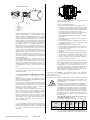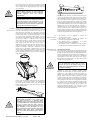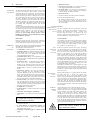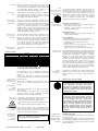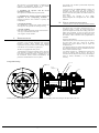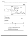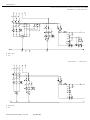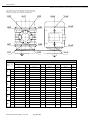
1
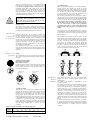
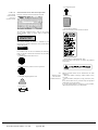
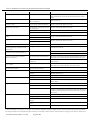
Directions for Use
and
Service Manual
for compact units of Types from WPB 120 to WPB 8300,
and of Types from WVB 120 to WVB 8300,
and
Base units of Types from WPB 120 to WPB 8300
BE 853
2.5.2004
Gardner Denver Schopfheim GmbH
Postfach 1260 • 79642 SCHOPFHEIM / GERMANY
Phone 07622/392-0 • Fax 07622/392300
[email protected]
www.gd-elmorietschle.com
TABLE OF CONTENTS
1.
Basic information
1.2.
Symbols used in the manual
2.
10.
Transport and transport data
2.2.
Handling
2.3.
Storage conditions
Pressure Device
Non-standard blower drive
Appendices
1. Identification of Characteristic Values, Standard compact unit Diagram, and
pressure ratios of standard blower set
Transport, Handling and Storage
2.1.
3.
9.
Introduction
1.1.
2.
3.1
Installation and Assembly
3.2
PVO Combined Safety and Starting Valve - Assembly
Forced and natural ventilation
Forced and natural ventilation
3.1.
Assembly conditions
3.2.
Space necessary for installation and operation
3.3.
Requirements for anchoring the blower set or blower
3.4.
Requirements for connecting the pipeline
3.5.
Instruction for connecting the blower set to the power supply
3.6.
Belt installation
3.7.
Precautionary measures
Catalogue sheet (dimensional drawing) of the compact unit in the acoustic
enclosure
3.8.
Machine hall ventilation
Quality certificate
Machine
Connection diagram of the electric motor (not included in this Manual,
submitted on request)
4.
4.1.
Blower description
4.2.
Blower set description
4.3.
PVO combined safety and starting valves
4.3.1.
Starting valve function
4.3.2.
Safety valve function
4.4.
Noise-damping hood
4.5.
Use
4.5.1.
Work media
4.5.2.
Suction and discharge temperatures
4.5.3.
Suction and discharge pressures
4.5.4.
Lubricant specification
4.5.5.
Maximum temperatures of the lubricating system
4.5.6.
Maximum speeds
4.5.6.1.
Pulley revolutions
4.5.6.2.
Work medium speed
4.5.7.
Necessary safety equipment
4.5.8.
Warning against use in explosion-hazard environments
4.5.9.
Recommendations for operation at a temperature of 0 oC and lower
4.5.10.
Application fields for blowers and blower sets
4.5.11.
Electrical equipment data
4.5.12.
Certificate of conformity
5.
Operating the Machine
5.1.
Inspection prior to first turning on the compact unit or base unit
5.2.
First turning on of the compact unit or base unit
5.3.
Trial Operation
5.3.1.
Check intervals for trial operation
5.4.
Emergency stopping controllers
5.5.
Setting and adjustment instructions
5.5.1.
Filling and changing the oil
5.5.2.
Replacing the filter inserts of the suction filter
5.5.3.
pulleys and belt tension
5.6.
Running without operators
5.7.
Plates and labels used on compact unit or base unit
5.8.
Instructions for tracing simple failures
5.9.
Routine maintenance and checks
5.10.
Service checks executed by the manufacturer
5.11.
Information on improper use
5.12.
Information on residual risks
5.13.
Places of excessively hot surfaces
5.14.
Equipment for protecting operators against residual risks
5.15.
Spare parts
6.
Taking the machine out of operation and waste disposal
7.
Noise level
8.
Training operators
Rietschle Thomas GmbH + Co. KG
page 2 / 23
4.
Connection diagram of the acoustic enclosure fan (3 x 400V)
5.
Connection diagram of the acoustic enclosure Fan (240 V)
6.
Report on measurement of blower set oscillation power
Catalogue sheet (dimensional drawing) of the compact unit
1. INTRODUCTION
1.1 BASIC
INFORMATION
2.
The Directions for use and service manual for the
SHARK compact unit and base units (hereinafter
referred to as the Manual) contain important directions to
be observed throughout the machine’s operating life,
starting on receipt of the machine. The manual has been
compiled for complete SHARK series. It also applies to
separately delivered base units. Before installing and/or
putting the machine into operation, you must familiarize
yourself with this manual in order to ensure trouble-free
and safe operation of the machine and a long operating
life. The manual mentions and quotes safety regulations to
be considered particularly during machine operation. It is
necessary that the personnel responsible for the machine
operation and maintenance have this manual at their
disposal so that operation and maintenance is done in
accordance with the instructions stated in this manual. We
recommend entrusting repairs and redesigns only to
Rietschle Thomas (RT) specialists. If under guarantee, the
machine shall be disassembled only by RT specialists or
persons authorized by RT.
The manual contains only instructions for use of standard
blowers and blower sets designed for air transport. The
instructions for use of non-standard blowers and blower
sets for transport of other gases must be consulted with the
manufacturer.
The instructions stated in the manual apply to the blower
set, the quality certificate of which is enclosed with this
manual. If any failure occurs, immediately contact the
Section for Business-technical Services (hereinafter
referred to as the RT service department). When
contacting RT about any problem, state the data from the
type plate: the type and serial number of the blower set or
blower.
1.2 SYMBOLS
USED IN THE
MANUAL
Caution: Read the directions for use!
Warning: Overlooking these instructions
might cause damage to the machine
and/or slight injuries.
TRANSPORT, HANDLING AND STORAGE
2.1 TRANSPORT
Delivery
AND TRANSPORT
Delivered blower sets are assembled as complete units.
Delivered belts are not installed on the machine. The
pendulous motor frame is secured by bolts in the bottom
position. Delivered compensators and non-return valves of
larger SHARK types (supplied with noise-damping hoods)
are not installed on the machine. Blowers are delivered
without oil fillings. The delivery contains the accessories
specified in the purchase contract. The dimensions and
weight are stated in the dimensional drawing of the
appropriate blower set, which is enclosed with the Manual.
DATA
Transport
Compact units must be transported in protected freight
space.
Blower sets must be transported with belts removed! Otherwise, the shaft or bearings could be
damaged. During transport, the pendulous motor
frame must be secured by appropriate bolts in the
bottom position!
Receipt
On receipt, the delivery must be checked with the delivery
notes for completeness. Any potential damage caused
during transport must be recorded in the presence of the
carrier. The record signed by the carrier must be
immediately submitted to the supplier.
2.2
HANDLING
To handle the machine, use a forklift truck and/or crane as
described below.
Base unit
The picture shows the handling of a base unit. To handle
the blower, use soft binding ropes. Steel wire ropes can be
used provided they are padded in order to prevent damage
to the paint.
Warning: Danger of injury
Warning: High temperature risk
Caution: Wear ear protectors!
WARNING
On no account should the blower be lifted with
the ropes attached to the flanges!
Oil filling
Forbidden: Do not turn on the machine!
Forbidden: Do not use a hammer!
Compact unit
To handle the compact unit, use a forklift truck and/or
crane. The following pictures show the ideal handling of
blower sets. To handle the compact unit with a crane, use
soft binding ropes. Steel wire ropes can be used provided
they are padded in order to prevent damage to the paint.
Further, you must avoid using too short binding ropes in
order to prevent deformation of the suction filter during
transport.
Suspension
Rietschle Thomas GmbH + Co. KG
page 3 / 23
WARNING
On no account should the compact unit be lifted
with the ropes attached to the set bases, blower
flanges, suction silencer, and/or motor!
Without a compact unit
With a compact unit
Acoustic enclosure
Smaller types of acoustic enclosures, in which compact
units are placed, can be handled by a crane or a forklift
truck. Ropes must be placed under the bottom base as
displayed in the picture - in the direction shown by the
arrows. The forks of the forklift truck must also be placed
in the direction shown by the arrows.
Larger types of acoustic enclosures are equipped with
lifting-eye nuts. If crane handling of the hoods is
impossible, they can be handled with a forklift truck. When
handling the enclosure with a forklift truck, you must put
baulks on the truck forks (where the enclosure is placed) in
order to prevent damage to the enclosure. The enclosure
can also be disassembled into individual parts and then
reassembled at the place of installation. The following
pictures show the handling of acoustic enclosures.
Motors
The handling of motors is described in the motor manual.
For handling, motors are usually equipped with eye screws.
Rietschle Thomas GmbH + Co. KG
page 4 / 23
The blower set must be stored in its original packaging in a
dry place and must be protected against dust. Compact
units in the acoustic enclosure intended for outside use can
be stored in the open air. If the blower set has been stored
for more than six months, you should (re)preserve it. For
this purpose, you can use standard preservative agents.
Storage conditions:
Temperature:
-30 °C up to 40 °C
Relative humidity: up to 80%
2.3 STORAGE
CONDITIONS
3.
Compact unit –
acoustic enclosure
Anchor
WPB/WVB 120 – 430
WPB/WVB 550 – 8300
K 42 - K 202
K 302 - K 802
Upat EXA M 8K
Upat EXA 12/15
Upat EXA M 8K
Upat MC 12/70
Assembly in the Open Air
To install the blower set (the set including the enclosure) in
the open air, you must consider the local conditions (snow,
possibility of flooding, etc.)
CONDITIONS
Service passages and the space necessary for the set
assembly in the machine hall are shown in Appendix 3.
Acoustic enclosures designed for outside use also serve as
weather protection.
Assembly in the machine hall
The minimum dimensions of the machine hall are based on
the maximum dimensions of the compact unit (acoustic
enclosure) and the necessary 1-metre (better 1.2-metre)
operation space at the sides of the blowers (enclosures) and
between the blowers (enclosures). They are further based
on the 1.2-metre space between the wall of the discharge
section at the acoustic enclosure and the wall. The machine
hall height depends on the method chosen for handling the
machine(s).
When designing the machine hall, you must remember the
openings for the blower sets (the delivered sets are
normally assembled). The acoustic enclosure are
demountable. You should consider equipping the machine
hall with an overhead track for a crane crab or leaving
enough space for a forklift truck in order to handle those
blower sets to be maintained or repaired (necessity to
dismantle the blower and/or motor if a failure has
occurred).
The space necessary for installation of individual types of
SHARK blower sets can be derived from the dimensions
stated in the dimensional drawings.
3.2 SPACE
NECESSARY FOR
INSTALLATION
AND OPERATION
3.3 REQUIREMENTS
BLOWER SET OR
BLOWER
8
12
8
12
3.4
REQUIREMENTS
Overpressure WPB:
F
TOP
TOP
4
1
WARNING
After being set in its position, the blower set must
be anchored to the floor. Otherwise, it could move
spontaneously and thus be damaged.
3
4
2
Overpressure WPB - central suction:
Working procedure for anchoring compact units and
acoustic enclosures.
1. Drill a hole and clean it;
2. Stick the anchor into the hole; and
3. Tighten the nut.
1)
2)
3)
OD
3
L
Rietschle Thomas GmbH + Co. KG
F
F Air flow
1. Non-return valve
2. O-ring
3. Compensator
4. Sealing
OD1
page 5 / 23
40
90
40
65
Connecting the pipeline to the SHARK compact unit
Since the entire aggregate is placed on rubber dampers, the
pipeline must be connected through flexible elements.
FOR CONNECTING
Otherwise, the running blower could shake the pipeline,
THE PIPELINE thus increasing the noise level. Standard compact units are
delivered with compensators for connection of the
discharge section. If a SHARK blower for vacuum is been
required or intended to be connected to the central suction,
a compensator for connection of suction is also supplied.
Delivered compensators and valves of larger blower sets
supplied with acoustic enclosures (from the K 302 type) are
not installed. These parts must be installed behind the
outlet flange of the discharge silencer or also in front of the
inlet flange of the suction silencer according to the
following pictures:
The floor designed for installation must be flat and
dimensioned for the machine weight and anchor length.
With respect to the loading capacity, no special
requirements are stipulated for the floor design since both
the blowers and motors are dynamically balanced. The
mechanical oscillation power of the blowers and motors are
stated in Tables 3 and 4. The weight of the blower set is
distributed between its individual bases. The weight of the
delivered blower set is stated in its appropriate dimensional
drawing.
The blower set must be positioned horizontally by placing
plates under the machine bases. The permitted deviation is
1 mm for 1 metre.
FOR ANCHORING THE
9
13
9
13
The space and diameters of the base holes are stated in the
enclosed dimensional drawing of the compact unit. The
procedure for anchoring acoustic enclosures is the same.
You should, however, pay attention to the tightness of the
gap between the hood and the floor. After setting the hoods
in their positions, you must also level any floor unevenness
in order to prevent the sidewalls from being tight. In order
to seal the gap between the hood and the floor, you can
apply polyurethane foam, for example. The electric cable
must be laid in the floor.
If you intend to put a blower set in the hood on a half grid,
you must order a non-standard enclosure because the
bottoms of the acoustic enclosures are not soundproof.
INSTALLATION AND ASSEMBLY
3.1 ASSEMBLY
OD [mm] OD1 [mm] L [mm]
4
0,05
Vacuum version WVB:
1
2
4
3
F
4
F
After the flanged connections have been tightened, the
blower must spin smoothly!
4
Rules for connecting the pipeline:
• The pipeline must be installed in the compensator axis.
• The pipeline must be placed on both fixed and sliding
points. It is not permissible to load the compensator with
the pipeline weight. The first fixed point of the pipeline
must be as near to the compensator as possible.
• The pipeline diameters should not be smaller than the
nominal inside diameters of the blower flanges.
• The recommended flow speed in the pipeline should be
below 22 m.s-1.
• If possible, large radii of pipe bends should be used (in
order to reduce loss).
• The closing fittings must be installed near the branches
in order to prevent impurities from accumulating in the
blind pipeline branches.
• Hot (discharge) pipelines should be insulated.
• The wall openings should be flexible and the pipeline in
them should be soundproofed (do not cement the
pipeline in the openings).
• Compensators should be installed on long and branched
pipelines.
• You should avoid the pipeline running perpendicularly
into the registers. You should check the lengths of those
registers where standing waves could occur for the
excitation frequencies of sextuple blower revolutions
(the frequency of the air pulsations).
3
F Air flow
1. Non-return valve
2. O-ring
3. Compensator
4. Sealing
While overpressure blower sets contain discharge pressure
gauges, vacuum blower sets contain suction pressure
gauges. If either a non-standard blower set or a separate
blower is delivered, a pressure gauge must be installed on
the pipeline as near the discharge flange of an overpressure
blower set/blower or the suction flange of a vacuum blower
set/blower as possible. Due to gas pulsation, it is necessary
to use pressure gauges resistant to cyclical fluctuations in
the pipeline pressure, for example glycerine-charge
pressure gauges. If you use an ordinary pressure gauge, an
absorber must be installed between the pipeline and the
pressure gauge. After setting the blower set in its position,
you must open the plugs of the glycerine-charge pressure
gauges in order to de-aerate them. Otherwise, they will
indicate incorrect values! If a blower set with a acoustic
enclosure is delivered, once it has been set up it is
necessary to interconnect the pressure gauges installed on
the enclosure and the measurement points on the blower set
with the supplied tubes.
For overpressure blower sets: the point on the blower’s
suction flange located below the suction filter must be
interconnected with the button connected to the pressure
gauge that is designed for measurement of filter insert
clogging. Further, the point on the discharge silencer must
be interconnected with the glycerine-charge pressure
gauge.
For vacuum blower sets: the point in front of the suction
filter must be interconnected with the pressure gauge
installed on the hood.
Connecting the Pipeline to the SHARK compact blower
You must ensure that the intake medium is free of
impurities.
Blowers could suck in outside air. Equipping the blower
with a suction filter produced by RT will suffice in order to
ensure purity of the intake air.
If a pipeline is to be used for transport of air to the suction
part, it is suitable to equip the blower with a RT suction
filter (used for vacuum blower sets) in order to connect the
pipeline. It is also necessary to install a compensator
between the suction filter and the pipeline.
If the intake air is filtered centrally for more blowers, you
must carefully clean the suction pipeline of foreign
particles. A compensator must be installed between the
blower and the suction pipeline. It is suitable to use a
suction sieve installed as near to the blower’s suction
flange as possible for the first 500 operating hours. Suitable
sieve densities can be derived from the following table,
which provides permissible sizes of impurities for
individual blower types:
It is not permissible to load the blower sockets with the
pipeline. Before being bolted together, the flanges of the
pipeline and the blower must fit closely. The maximum gap
in the gasket circumference can be 0.05 mm, as shown in
the picture.
Rietschle Thomas GmbH + Co. KG
page 6 / 23
When designing pneumatic transport, cement clarification,
and similar applications where contaminated transported air
(the volume between the non-return valve and the
technological device) could expand after the blower has
been turned off, you must consider such applications or
ensure that the pollutants are separated when the air is
flowing back (the mechanical non-return valves do not
close immediately). Contact RT in these cases.
3.5 INSTRUCTIONS
Warning: Only authorized persons with appropriate
FOR CONNECTING electrical qualifications are allowed to connect electrical
THE BLOWER SET TO
devices.
THE POWER SUPPLY Blowers, compact units, acoustic enclosures and electric
motors are equipped with earth lugs. The protection of the
standard blower set is determined by the electric motor
protection (IP 55).
The wiring must meet the requirements for machinery in
accordance with the 98/37/ES Directive and primarily the
requirements stipulated in the EN 60204-1 Standard. Such
requirements must be ensured by the electric part supplier.
The standard deliveries of the RT blower sets contain only
the electric motor terminals. If the delivery also includes
the control system, only the power cable (if not included in
the delivery) must be installed and connected. More
detailed instructions are given in the separate manual for
the control unit.
The supply cable must not restrict the movement of the
motor and its pendulous frame!
Electric motors should be connected in accordance with
Blower WPB /
WVB
Permissible
impurity size [mm]
120
300
400
430
550
750
780
1000
1300
1600
2000
3000
4000
5000
6500
7000
8300
0.01
0.05
0.07
0.09
0.1
0.2
recommendations from their Manufacturers. The
connection diagram is attached to the inside of the cover of
the electric motor’s terminal block. We recommend starting
the electric motors in the star-delta connection (soft-start,
etc.) even when the user could connect high-power electric
motors directly (in the delta connection). The “soft” start
saves the blower.
WARNING
Electric motors with power of over 11 kW must
not be started directly (in the delta connection)
without
approval
from
the
blower’s
manufacturer.
Before putting on the belts, you must remove the supports
securing the pendulous motor frame in the lifted position.
When gradually lowering the pendulous motor frame, you
must ensure that the belts remain in the pulley grooves.
Since the pendulous motor frame is secured in its working
position only by tightened belts, you must therefore prevent
it from sudden loosening (with a jack, for example) before
adjusting the stop. The stop bolt must be adjusted to a
sufficient height so that the pendulous motor frame does
not hit it when the motor is starting. When new belts are
being installed, it is better to leave a larger gap between the
stop bolt and the pendulous motor frame as the frame will
lower after the belts have been set in their positions.
The electric motors of the compact units with
acoustic enclosure must be connected so that they
cannot be turned on if the electric motor fans in
the acoustic enclosure are not running – the fans
must exhaust air from the enclosures. Appendices
9 and 10 show the connection diagrams.
3.6 BELT
INSTALLATION
Due to transport of blower sets, the delivered belts are not
installed and the pendulous frame with the motor is secured
by bolts in the bottom position. Belts can be put on only
when the blower set has been set in its position. You must
first remove the bolts securing the pendulous motor frame
in the transport position. In order to lift the frame, you must
use a jack with the appropriate lifting capacity. An arrow
shows the point to place the jack. For smaller blower sets
(up to the size 2000), it is sufficient to use a screw jack
with a lifting capacity of 700 kg (the type used for lifting
private cars). For larger blower sets [from the size 3300
with motors from the 280 type (axial height in
millimetres)], you must use a jack with a lifting capacity of
2,000 kg, preferably a hydraulic one. The jack must be
placed on a solid base. If the jack is placed on a smooth
surface, such as a pavement or painted surface, you must
secure it with a rubber pad, for example, in order to prevent
it from slipping. Before starting any operation, you must
prevent the lifted pendulous motor frame from falling by
using suitable supports.
3.7
PRECAUTIONARY
MEASURES
3.8 MACHINE HALL
• The machine owner is obligated to observe the
provisions of this manual.
• The machine owner is obligated to maintain the
minimum spaces stipulated in this manual.
• The machine owner is obligated to see to good
readability of safety labels and markings.
• The machine owner is obligated to provide operators
with the protective equipment stipulated in this manual.
Machine hall ventilation
VENTILATION The machine hall is warmed by the heat radiated from the
motors, blowers, discharge silencer and discharge pipeline.
In order to reduce the machine hall temperature, the heat
must be suitably dissipated (machine hall ventilation). If
the output temperature is high, it is necessary to insulate the
outlet pipeline. In most cases when blower sets suck air
directly from the machine hall, you must ensure forced
ventilation of the machine hall.
WARNING
It is not permissible to direct flow of cool air
towards any part of the blower casing. Local
cooling causes thermal deformation – the blower
could thus be damaged.
On the inside of the frame sidewall below the pendulous
motor frame, you must then install a stop checking the
lower limit of the pendulous motor frame misalignment.
Before putting on the belts, you must screw the stop bolt
into its bottom position.
WARNING
When putting on the belts, be very careful you do
not injure yourself by a suddenly falling
pendulous motor frame that might come loose.
You must hold the belt only at the place that will
not be in contact with the pulley when the
pendulous motor frame has been lowered. It is
also forbidden to touch the blower set at the
places between the edges of the sub frame and the
pendulous motor frame, where a cutting effect
will occur when the pendulous motor frame is
moving.
Rietschle Thomas GmbH + Co. KG
page 7 / 23
Appendix 8 shows the ventilation diagram. When
designing the machine hall, you must remember sufficient
openings for both cooling air intake and warmed air
exhaust. It is assumed that the fans will be located in the
exhaust section. Cooling air intake for the blower suction
from the machine hall must be designed so that sufficient
volumes of both cooling air and air sucked by the blower
set are ensured. If the intake air is transported from outside
by a pipeline, it will suffice to dimension the inlet opening
only for the cooling air volume and fit the exhaust section
with fans of the required capacity. The air speed in the
openings should range between 5 m.s-1 and 10 m.s-1. The
suction and exhaust openings must be designed so that no
noise will escape from the machine hall.
4.
4.1 BLOWER
DESCRIPTION
4.2 BLOWER
SET
DESCRIPTION
MACHINE
• Optional accessories:
The RT SHARK-compact units sets are fitted with RT base
units of the Roots type with three-tooth rotors.
a) A suction pressure gauge, or an electric indicator of
filter clogging instead of the visual indicator.
The Rietschle Thomas Roots blowers work on the principle
of oil-free gas transport. These blowers are the most
widespread type of two-rotor blowers. The axes of the rotor
rotation are parallel. A synchronizing gear, both of whose
wheels have the same number of teeth, moves the rotors.
The synchronizing gear ensures contact-less movement of
the rotors. The rotors turn against each other. Both the
suction and discharge sockets run between the rotor axes.
The blower transports gas without increasing the pressure.
Gas is compressed in the discharge socket by the gas that
has already been transported (blowers with external
compression).
The rotor seals of the standard blower types are not subject
to wear. Since the seals do not ensure absolute tightness of
the blower, the oil levels in the covers must not exceed the
stipulated limits. Otherwise, oil could leak into the
blower’s working space or outer space. In order to
prevent oil from leaking during transport and/or
handling of the blower, you must fill oil before putting
the machine into operation.
b) An electric motor. You can choose a fixed-speed or
two-speed motor or a type of motor where a frequency
converter changes the motor revolutions.
• Special accessories:
a) A acoustic enclosure for inside or outside installation.
b) Pressure and temperature sensors.
c) An auxiliary discharge silencer of the vacuum blower
set. It (usually with a acoustic enclosure) serves to
reduce noise made by air being released into the blower
set’s surroundings.
4.3 PVO
COMBINED SAFETY
Functions
The PVO combined valve has two functions. When the
blower is starting, the valve gradually increases the air
VALVES pressure, thus increasing the torque – starting valve
function. When the blower is in operation, the valve
protects it against overload (against pressure increase over
the permissible limit) – safety valve function.
AND STARTING
Blower Drive
Valve description
Blowers are mostly driven by electric motors. A belt drive
normally transfers the torque from the motor shaft to the
blower shaft. The blower shaft is a part of one rotor.
The numbers of the main parts correspond to the numbers
of the positions shown in Appendix 4 (PVO combined
valve assembly): control valve (1), mobile base (2), bottom
base (3), top base (4), bellows flange (5), hose (6), guide
rod (7), bellows (14), and springs (15).
Blower sets are shown in the dimensional drawings of the
individual types that are enclosed with this Manual.
The main parts of the blower sets are:
• A suction filter - a resonance silencer with a filter insert.
• A discharge silencer - a welded construction of the base
frame and the vessel. It serves as a supporting element
for the blower and is also designed to suspend and
secure the pendulous motor frame.
4.3.1
STARTING
VALVE
FUNCTION
• A pendulous motor frame - it is suspended by pins in
the silencer frame. It enables the belts to be tightened by
tipping the motor.
• A non-return valve – an inter-flanged type. The nonreturn valve of the overpressure machine type is
installed at the discharge section while that of the
vacuum machine type is installed at the suction section.
• A safety valve - it serves as overload protection of the
blower.
a) Overpressure version: if the valves are opened, air
(gas) is released into the atmosphere. Directly
controlled, HEROSE spring valves are used in smaller
blower sets. Their opening pressure is set by spring bias.
Larger types of blower sets are protected indirectly by
controlled combined safety and starting valves (see the
PVO valve description for more detail information).
4.3.2 SAFETY
VALVE
FUNCTION
b) Vacuum version: if the vacuum set by the spring has
been exceeded, the seat will lift and air will be sucked
from the atmosphere into the suction pipeline. The used
valves are directly controlled and spring-operated. Their
opening pressure is set by spring bias.
• A compensator - metal bellows.
• An electric motor - a bottom, fixed-speed or two-speed
electric motor.
• A belt drive with V-shaped or toothed belts.
• A belt guard - it is made from common constructional
steel.
The standard blower sets in acoustic enclosures are
not equipped with a belt drive guard because the
enclosure itself protects the drive.
• Bases with rubber dampers - they minimize transfer of
vibrations to the bases.
• A visual indicator of suction filter clogging. For
blower sets in acoustic enclosures, a pressure gauge is
used instead of the indicator.
• A discharge overpressure gauge or a suction vacuum
gauge.
Rietschle Thomas GmbH + Co. KG
page 8 / 23
4.4 NOISEDAMPING
HOOD
If there is no pressure, the main valve is open – the springs
(15) lift the bottom base (3). When the blower is starting,
pressure is generated in the gap between the seat and the
disc. The control valve will feed the pressure into the
bellows. As the bellows area is larger and the bellows
power is higher than those of the seat, the bellows will
close within several seconds due to gradually increasing
pressure, thus enabling the blower to start with the load
increasing fluently. The bellows must simultaneously press
the springs (those ensuring that the unloaded valve will
open). If the unloaded valve were closed, it would not serve
as a starting valve. By removing the springs, you could
disengage the starting valve function.
By installing a solenoid valve (a special design), you could
control the blower’s start-up time electrically. When the
electromagnet of this valve is turned on, the inner space of
the bellows is interconnected with the atmosphere and the
main valve is open.
During normal operation, i.e., after the blower has started,
the main valve disc is closed. The control valve
interconnects the spaces of the outlet pipeline and the
bellows. If pressure exceeds the adjusted limit, the control
valve will release it into the atmosphere. This will result in
reducing the pressure in the bellows and opening the main
valve disc. After the pressure has dropped, the control
valve will stop releasing the pressure into the atmosphere,
thus increasing the pressure in the bellows and closing the
main valve disc.
Acoustic enclosures serve to reduce the blower set noise.
Acoustic enclosures are steel with absorption damping
material. The enclosures are equipped with fans ensuring
forced ventilation. The intake and exhaust openings for
cooling air are fitted with silencers. During forced
ventilation, the fan exhausts air out of the enclosure. The
enclosures enable the machine to be installed both outside
and in the machine hall. The types of outside enclosures up
to K 552 differ from the inside enclosures only in their
finish. The K 802 outside enclosures also have small roofs.
You can find the dimensions of the appropriate enclosure
types in their dimensional drawings.
CAUTION
Forced acoustic enclosure ventilation does not
replace machine hall ventilation.
4.5 USE
4.5.1 WORK
MEDIA
4.5.2 SUCTION
AND DISCHARGE
TEMPERATURES
4.5.3 SUCTION
AND DISCHARGE
PRESSURES
4.5.4 LUBRICANT
SPECIFICATION
Blowers are used to transport and compress gases. Since
the rotors neither touch each other nor are in contact with
the casing, blowers are suitable for oil-free transport and
gas compression. During transport, media are not
contaminated with either abrasion particles or oil.
FOR OPERATION AT A
Standard blowers are designed to compress or exhaust air
or non-aggressive and non-explosive gases. If you may
need further assistance in using the blower with special
gases, please contact Rietschle Thomas.
Suction and discharge temperatures depend on the
compression degree. Both temperatures are stated in the
calculation of the blower set parameters. Such calculations
are included in the offers of the blower sets. In standard
blowers, the maximum temperature of the discharged
medium is 140 °C. In order to prevent the temperature from
exceeding the limit value in the discharge section (even
during the highest medium compression), the intake
medium temperature must be below 40 °C.
120
300, 400
430, 550, 750
780, 1000, 1300
1600, 2000
3300
4000, 5000
6500, 7000, 8300
4.5.5 MAXIMUM
THE LUBRICATING
SYSTEM
°C AND LOWER
FIELDS FOR BLOWERS
AND BLOWER SETS
SPEEDS
REVOLUTIONS
Other Applications
- Backward rinsing of filters in water treatment plants;
- Release of material from silos (storage tanks);
- Clarification of loose materials and mixtures;
- Vacuum transport;
- Exhaust of air from various equipment systems at an
absolute pressure of up to 500 mbar; and
- Supply of process air at a pressure of up to 1000 mbar.
4.5.11 ELECTRIC The standard deliveries of blower sets contain no wiring or
Oil charge
Drive side
[l]
0.07
0.1
0.2
0.55
0.75
1.5
1.4
5
EQUIPMENT DATA
Gear side
[l]
0.1
0.15
0.45
0.7
1.4
2.75
2.6
6
Total
[l]
0.17
0.25
0.65
1.25
2.15
4.25
4
11
Use of different oils (e.g., for applications in the foodprocessing industry) must be consulted with Rietschle
Thomas.
Electric motor lubrication is described in the enclosed
electric motor manual. There are no other lubrication places
in the blower sets.
4.5.12
CERTIFICATE OF
CONFORMITY
5.
The maximum temperature of the oil charges must not
exceed 120 °C (standard stabilization of the blower
bearings).
The maximum revolutions of the pulleys correspond to
those of blowers.
The used designs of the pulley guards or the acoustic
enclosures are tough enough to withstand any damage
(break-off and/or tear) caused by broken belts.
EQUIPMENT
4.5.8 WARNING
AGAINST USE IN
THE EXPLOSIONHAZARD
If the delivery contains no blower discharge pressure
gauge, you must install it on the discharge pipeline. The
used pressure gauge must be glycerine or with an absorber
in order to ensure reliable functioning.
WARNING!
Blowers of standard types are not designed for
use in explosion-hazard environments!
5.1 INSPECTION
PRIOR TO FIRST
TURNING ON THE
BLOWER SET OR
ENVIRONMENTS
BLOWER
Rietschle Thomas GmbH + Co. KG
page 9 / 23
A Declaration of Conformity in accordance with the Czech
Republic’s Act No. 22/97 Coll. and the European Union
Council’s Directive No. 98/37/ES is enclosed with this
Manual.
OPERATING THE MACHINE
Since acoustic enclosures have the same function
as belt drive guards during machine operation,
standard blower sets placed in acoustic enclosures
are not equipped with these guards. Only
authorized persons whose familiarization with the
risk of touching rotating parts can be proved are
allowed to execute operations that are directly
related to putting the blower set into operation,
and those operations that must be performed
when the acoustic enclosure during blower set
operation.
4.5.6.2 WORK - The speed in the openings for intake and exhaust of air
from the machine hall: between 5 m/s and 10 m/s;
- The recommended speed in the pipeline: 22 m/s;
- The maximum speed in the discharge pipeline: 35 m/s;
and
- The maximum speed in the suction pipeline: 30 m/s.
SAFETY
control units. The basic data about the installed electric and
electronic devices are stated on their type plates and in their
accompanying documentation (manuals, connection
diagrams, etc.). The electric part supplier must ensure
conformity with the requirements of the appropriate
standards. The requirements for of equipment with electric
motors, the nominal current of which is below 16 A, were
not verified because the emission of such equipment
depends on the installation and properties of the equipment
complex where the equipment is used. If the delivery
contains a switchboard with a control unit, the unit’s basic
data are stated in separate operating instructions.
For at least the guarantee period, you must keep
an operating diary where you record operating
dates, maintenance, inspections, and repairs.
Keeping the operating diary during the guarantee
period is a precondition for accepting guarantee
claims. This applies particularly to the checks
stated in Tables 5 and 6.
MEDIUM SPEED
4.5.7 NECESSARY
- Increasing the volume of oxygen in water and keeping
bacteria above the surface; and
- Ventilating activated sludge and detritus tanks in
wastewater treatment plants.
Pneumatic Transport
- Transporting all kinds of loose materials, granules, and
variously-grained materials.
4.5.6 MAXIMUM
4.5.6.1 PULLEY
can be operated for a short time at a temperature as low as
-30 °C. Such restrictions apply particularly to the belts,
standard types of electric motors, and PVO valves. The
blower set contains no water cooling. The minimum
volume of condensate that builds up in the discharge
pipeline cannot affect the blower set operation.
4.5.10 APPLICATION Wastewater Treatment Plants
The following table provides oil charge volumes for
blowers:
The prescribed oil is fully synthetic motor (automotive)
oil, Rietschle Thomas GEAR LUBE 150:
TEMPERATURES OF
TEMPERATURE OF 0
The suction and discharge pressures are stated on the type
plates of the blower sets and in the calculations of the
blower set parameters. The maximum permissible
differential pressure is stated on the blower type plates. The
pressure at the blower’s discharge flange is referred to as
pv, the pressure at the blower’s suction flange is referred to
as ps, and the pressure at the flange that connects the
blower set with the pipeline system is referred to as p3.
Oil charge volumes
Type WPB / WVB
4.5.9 The minimum ambient temperature when the blower set
RECOMMENDATIONS operation is still stable is -20 °C. Nonetheless, blower sets
Installation Inspection
- Check the installation of the machine and attachment of
the anchoring bolts;
- Check proper installation of all parts that could be left
unattached during installation. Check especially those parts
that could endanger the operators if they were not attached
and/or installed; and
- Check all valves in the discharge pipeline whether they
are open.
You must turn the nut until it moves with difficulty, then
turn the nut a further approximately 180°. The cone will be
unloaded and the safety valve will start releasing air. Then
you must tighten the nut again. Larger blower sets are
equipped with safety valves with control valves. After one
end of the hose has been disconnected from the control
valve, the “bellows” space will open into the atmosphere
and the valve will open automatically. After re-connecting
the hose, you must check the joint for tightness (for
example, with soapy water).
Connecting elements
- Check whether all connecting elements are installed and
tight.
Filling with oil
Blowers are transported without oil. The approximate
volumes of oil charges and the recommend types of oil are
stated in Table 1 and Table 2 respectively (Chapter 4.5.4).
On no account should oils be mixed! See Chapter 5.5.1 for
more information.
5.3 TRIAL
• Check, monitor and document the operating pressure
and temperature;
• Monitor the noise level and vibrations when the blower
set is in operation;
• Check the temperature on the blower surface for local
overheating; and
• Check the state and volume of oil in the oil level gauges.
OPERATION
Movement inspection
Check whether the blower moves smoothly (turn the pulley
slowly with your hand).
WARNING!
You might be hurt when turning the pulley. You
must hold the pulley at the places of contact with
the belt **).
120
300
400
4000 6500
3300
5500 7000
3000 2600 2200
Oscillation
power
<2 <3 <3
<4
<4
<5
<5
<6
<7
<7
<8
<8
[mm.s-1]
Note: The power of blower mechanical oscillation is in accordance with the ČSN ISO 3945 Standard.
8300
1850
<9
**
**
WPB/WVB
Type
Blower revolutions [1.min-1]
430
780
750
1300 1600 2000
550
1000
5000 6000 5600 5500 5250 5250 4600 3000 3500
Motor
Dmychadlo
Table 3 – Maximum oscillation power of blowers
Table 4 – Maximum oscillation power of electric motors
ELECTRIC MOTOR
Type
Be careful you do not crush your fingers!
Pipeline Inspection
Check whether the suction and discharge sides are clear.
Inspection of the direction of rotation
Turn the blower on for no more than 1 second. If it were
turned on for a longer time and the direction of rotation
were incorrect, the blower could be damaged. The blower
drive must turn in the direction indicated by the arrows.
56 - 132
Category
N
No. of poles
2,4,6,8
4,6,8
5.3.1 CHECK
INTERVALS FOR THE
TRIAL OPERATION
Backward running will damage the blower.
Do not turn the blower on again when it is still
running down. Otherwise, it could be seriously
damaged (the blower must be turned on only
when at a standstill).
5.2 FIRST
TURNING ON THE
BLOWER SET OR
BLOWER
N
2
2,4,6,8
250 - 280
R
4,6,8
N, R
2
4,6,8
2
315 - 355
N
R
2,4,6,8
2,4,6,8
Oscillation
power
< 1.8
< 0.71 < 1.12
< 2.8
< 1.12
< 1.8
< 4.5
< 4.5
< 4.5
< 1.8
[mm.s-1]
Note: The power of electric motors’ mechanical oscillation is in accordance with the ČSN ISO 35 0000
Standard, Part 14 (IEC 34-14), Category N – normal, Category R – reduced.
If the values stated in Tables 3 and 4 are exceeded, you must contact the RT service department!!!
FORBIDDEN!
FORBIDDEN!
160 - 225
R
5.4
EMERGENCY
STOPPING
CONTROLLERS
- During the first two operating hours, a permanent
operator records values in a report every 15 minutes.
- During the next two operating hours, the permanent
operators record values in the operating diary every 30
minutes.
- During another eight operating hours, the permanent
operators hourly record values in the operating diary.
No emergency stopping controllers are normally delivered
with the RT compact units. The electric part supplier is
required to ensure their installation.
Take care the following steps:
•
•
•
•
•
•
Open the acoustic enclosures (if installed).
Turn on the electric motor. Check the position of the
stop bolt (the pendulous motor frame must not hit the
bolt).
Check the functioning and adjustment of the safety
valve when the machine is in operation.
After approximately 1 minute, check the operating
pressure. When the specified pressure is reached, turn
off the drive unit.
Observe the blower running down. The blower must
run down smoothly, without impacts and/or sudden
stop.
Check whether the direction of fan rotation is correct air must flow from the opening above the top wall of
the noise-damping hood.
Safety valve functioning inspection
You should check the functioning of the safety valve and
the mobility of the sealing cone during operation, at a
pressure of 80% (or higher) of the opening pressure. If
HEROSE valves are used in smaller blower sets, it is
necessary to check the cone mobility. You must unload the
cone by loosening the knurled nut in the valve body cover.
Rietschle Thomas GmbH + Co. KG
page 10 / 23
5.5 SETTING
AND
ADJUSTMENT
INSTRUCTIONS
5.5.1 FILLING AND
CHANGING THE OIL
The blower has two separate oil charges.
Oil is filled through the filling holes in the tops of both
covers. After removing their caps, you can pour in oil. You
should use a funnel so that oil will not leak uncontrollably
into the surroundings, stain the belt drive, etc.
Oil is discharged through the drain holes in the cover
bottoms. Used oil must be drained into sufficiently large
tanks. After removing the drain hole cap, you must also
remove the filling hole cap so that oil can drain freely into
the tank and a vacuum cannot build up when oil is being
discharged. You must visually check the used oil whether it
does not contain metal particles or metal dust. The presence
of such substances might indicate the initial stage of
malfunction of either the bearings or the gear. In such
cases, you must contact the RT service department.
The blower can be refilled with oil only when all the
remaining oil has drained away and the drain hole cap is
closed.
While the maximum oil level is in the middle of the oil
level gauge, the minimum level is 3 mm lower. The oil
level measured when the machine is turned off must be
maintained within these limits. When the oil level has
reached the minimum, you must immediately top up with
oil. Top up with oil carefully so that its level will not be
above the middle of the oil level gauge. Otherwise, oil
could leak through the release openings or into the blower
when the machine is in operation.
V-belt Maintenance
Belts are tensioned depending on the transferred output.
During operation, the optimum belt tension is ensured
automatically by tilting of the pendulous motor frame. The
tilt of the pendulous motor frame is limited by the stop bolt
(see Chapter 3.6). After the belts have been lengthened,
you must readjust the bolt so that the pendulous motor
frame will not hit it when the motor is starting.
The belt drive parameters (the sizes and types of pulleys
and the number and sizes of belts) have been designed and
optimized for the required gear ratio and transferred output
so that the V-belts will be maximally employed. If any
functional drive belt is missing, you must always put on
the belt drive a new set of belts of the same type and
size. You must always use belts with a guaranteed
peripheral speed of 50 m.s-1! You can find the type and
length of belts in the Certificate of Completeness and
Quality.
Depending on the operating conditions, the blower oil
temperature could exceed 100 °C. Thus, you must
drain and top it up with oil when it is cool!
Otherwise, you could burn yourself.
Greases (motor):
The bearings of the smaller standard electric motors are
lubricated by a permanent grease charge. The bearings of
the larger electric motors must be greased. The greasing
procedure is described in the directions for motor use.
Long operating life of the designed belt drive is assured if
all conditions for regular maintenance are observed and the
replaced belts are the same as those originally designed by
Rietschle Thomas.
5.5.2 REPLACING Increased underpressure in the blower’s suction part
THE
FILTER INSERTS OF
THE SUCTION FILTER
indicates suction filter clogging (indicated by a red strip in
the filter clogging sensor). If a pressure gauge is used
instead of the filter clogging sensor, the working section
and the state of increased underpressure are marked in
green and red respectively. If the filter is clogged, you must
replace its filter insert. You can order filter inserts; their
part numbers are stated on their flanges or in the Certificate
of Completeness and Quality.
After replacing the filter insert, you must release (by
pressing) the mechanical catch of the filter clogging sensor
so that the red strip indicating increased underpressure will
disappear.
The parallelism of the shafts of both the blower and the
motor and the alignment of the pulley grooves are ensured
when the machine is being produced. When reassembling
the pulley, you must put it on the shaft so that the faces of
both pulleys are levelled. The maximum permissible
deviation is 0.4% (the maximum gap between the rule and
the pulley is 4 mm per one metre). When reassembling the
motor, you must ensure that the shafts are parallel and the
pulleys are levelled according to the picture:
5.5.3 PULLEYS AND Pulleys
BELT TENSION
The standard blower sets are equipped with V-belt drives.
Taper Lock bushings transfer the torque from the pulleys to
the shafts.
Taper lock clamp bushings –
Disassembly and assembly
Disassembly procedure
Loosen and remove all bolts. Screw bolts onto the releasing
threads. Tighten the bolts evenly (gradually tighten the
bolts opposite one another) until the clamp bushing is
released from the pulley.
Releasing thread
1/2 thread
Releasing threads
1/2 thread
5.6 RUNNING
WITHOUT
OPERATORS
Securing threads
1/2 thread
Securing threads
1/2 thread
Assembly procedure
Degrease the shaft journals, clamp bushing and pulley
hole. Put the clamp bushing in the pulley. Position the half
threaded hole so that the holes of the bushing and the
pulley fit. Oil the bolts slightly and screw them into the
securing holes. Do not tighten them yet! Put the clamp
bushing together with the pulley on the shaft. Now you can
evenly tighten the bolts with a torque wrench. Tighten them
gradually up to the stated torque (Ms). Check the bolts for
correct tightening (according to the torque) after the clamp
bushings have been in operation for a short time. Put grease
into the empty threaded holes to prevent dirt from
collecting.
Table 5 – Torques according to the clamp bushing types
Type
Ms [Nm]
Type
Ms [Nm]
1008
5.6
2517
48
1108
5.6
3020
90
1210
20
3030
90
1215
20
3535
112
Rietschle Thomas GmbH + Co. KG
1310
20
4040
170
1610
20
4545
192
1615
20
5050
271
page 11 / 23
2012
31
Since blowers normally work without operators being
present, they must be protected against overload and/or
sudden failures.
The electrical part supplier is responsible for current
overload protection.
The machine owner must ensure that the machine will not
be overloaded by the safety valve’s being permanently
relieved. This applies mainly to simultaneous operation of
several blower sets (e.g., in wastewater treatment plants)
when one discharge branch is closed but the volume of
supplied air is not reduced to the necessary volume (by
reducing the revolutions or turning off one of the blower
sets). Blower set operation during which the safety valve
releases air for a long time causes pressure fluctuations that
significantly shorten the operating life of both the bearings
and the non-return valve. They might also damage the
blower.
In order to ensure thermal overload protection, it is suitable
to arrange electrical control of the permissible temperatures
of both the discharged air and the surroundings (a thermal
sensor connected to a signalling device or machine
stopping).
- C 21 Suspension point
5.7 PLATES
AND LABELS
USED ON BASE
UNITS AND
COMPACT UNITS
Plates and labels on base units and compact units:
Base unit, compact unit and sound enclosure plate
- Plate - warning
- “ATTENTION“ red plate.
On the suction silencer or the acoustic enclosure.
The following cardboard label is hung on the suction
sensor, pressure gauge or blower itself (if delivered
separately):
TRANSPORTED
WITHOUT OIL
The correct direction of rotation is indicated by the
following arrow placed on the blower cover (near the shaft)
and the belt guard:
In accordance with the EN 1012 Standard, the following
labels are placed on the blower and blower sets (according
to their types):
- C1 Order: Read the Directions for Use
- “ATTENTION: CUTTING EDGE“ plate.
On the sub frame of the blower set, below the pendulous
motor frame.
- C2 Required activity: Order to wear ear protectors
5.8
- C7 Warning: High temperature risk
INSTRUCTIONS
FOR TRACING
SIMPLE FAILURES
- C19 Oil filling
Rietschle Thomas GmbH + Co. KG
page 12 / 23
Blower operation failures can be divided into two main
categories:
- Mechanical failures (bearings, toothed wheels, rotors,
etc.); and
- Electrical failures (faulty drive, wiring, contactors, fuses,
etc.).
If any electric failure occurs, you must notify the specialists
authorized to repair such failures.
If you are unsure about the correctness of your procedure,
call the Rietschle Thomas service department.
LIST OF POSSIBLE FAILURES AND METHODS FOR REMOVING THEM
FAILURE
POSSIBLE CAUSE
REMOVAL
The machine will not start
Electrical part failure
Check the wiring, contactors, fuses, thermal or other protection, and
cable connection state. Check the state and functioning of the electric
motor.
Oil leaks through the ventilation openings
High oil level (measured when the
blower is turned off)
Drain excessive oil.
Elevated noise level, the blower makes a
“metallic” sound
Blower rotor knocking, bearing failure or
incorrect setting of the limit clearances
Repair by the Rietschle Thomas servicemen
High current consumption
Bearing failure or seizing of the rotors in
their working space
Repair by the Rietschle Thomas servicemen
High overpressure in the outlet pipeline
Measure the overpressure and remove the cause.
High vacuum
Replace the filter inserts.
High temperature of the cover at the blower
pulley
High temperature of the cover at the gear
No oil in the blower
Repair by the Rietschle Thomas servicemen
Bearing failure
No oil in the blower
Repair by the Rietschle Thomas servicemen
Failure of the bearing or gear
Slipping belt
Greasy belt
Clean both the belt and the pulleys and degrease them with petrol.
The blower is loaded immediately after
start-up (applies only to blower sets with
PVO valves)
Disengaged starting valve function
Set the combined safety and starting valve so that it will be open when
the machine is turned off.
The blower turns spontaneously in the
opposite direction when being turned off
Malfunctioning non-return valve
Check the non-return valve and replace if necessary.
The safety valve releases air when the
blower is in operation
High overpressure in the outlet pipeline
Measure the overpressure in the outlet pipeline and remove the cause *)
The safety valve is set for maximum + 10% of the outlet overpressure.
Failure of the combined safety and
starting valve
Remove leakage and dirt from the control valve, and/or replace the
rubber bellows.
The safety valve sucks air when the blower
is in operation
High vacuum in the inlet pipeline
Measure the vacuum in the inlet pipeline and remove the cause *)
The safety valve is set for maximum + 10% of the vacuum.
The safety valve will not open when the full
blower load is exceeded
The safety valve is clogged with dirt
(applies to the Herose valves)
Disassemble and clean the valve.
An overheated blower
Dirty filter insert
Replace the filter insert.
Overload
Maintain the load - data.
Large piston clearances
Repair by Rietschle Thomas
Incorrectly installed non-return valve
Repair the installation.
Slipped or broken belt
Belt failure and/or incorrectly set pulleys
Blower failure
Incorrectly dimensioned blower
Compare the values with the efficiency table.
Leaky safety valve
Check the valve setting and operating pressure.
Slipping belt
Check visually the operation of the belt whether it runs without
vibrations. Check the motor power. Recheck the belt state. Set the lower
possible limit of the pendulous motor frame position lower by adjusting
the stop bolt.
The rotors touch each other
Check the bearings and gear setting.
Damaged bearings
Replace the bearings and change oil
Incorrectly aligned pulley and/or
coupling
Adjust it/them and tension the belt of the belt drive.
Loosened bolts securing the motor and/or
blower
Tighten and adjust them.
Rotor imbalance due to dirt
Clean the transport space and rotors.
No transport
Low supplied volume
Vibration
Disassemble the pipeline and replace the sealing ring.
*) The cause might lie in a project error, for example. At a specific flow, the pipeline resistance is higher than the overpressure (required when the blower parameters
were being specified). This is usually detected when the blower is first turned on and/or when the projected machines are being put into operation. Another cause
Rietschle Thomas GmbH + Co. KG
page 13 / 23
might be a change in the resistance after the machine has been operated for some time. This is caused by pipeline clogging, clogging of the tanks’ aeration openings
in wastewater treatment plants, etc., or by operators’ unfamiliarity (see Chapter 5.6).
5.9 ROUTINE
MAINTENANCE
Table 5 – Blower checks
Operating time
AND CHECKS
After 400 hours
Check
Blower operation check.
In a dry continental climate, preserve the rotors and cylinders after a
six-week standstill. In a humid climate, preserve them sooner (see
Chapter 2.3).
Check of the lubrication discs functioning
(the level moves slightly).
Oil change
After 4,000 2) hours
After 20,0001) hours
1)
After 40,000 hours
Lubrication
Check of the oil bath levels.
First change of oil since the machine was
put into operation.
Oscillation power measurement (bearings)
Bearings check by oscillation power measurement. Expected
replacement of the bearings.
Oil change
Notes:
1) Executed by the Rietschle Thomas servicemen.
2) The oil change interval depends on the operating temperature of the oil bath (it also depends indirectly on both the input and output temperatures of the
transported air). If the oil temperature does not exceed 50 °C, you can change oil annually (after 8,000 hours). If the temperature is higher than 100 °C, you must
change oil four times a year (after 2,000 hours). If the temperature is 120 °C, you must change it monthly. You can detect the oil state by comparing an oil sample
with new oil. Dark and/or thick oil indicates contamination or the initial stage of carbonization; i.e., you must change it. Analyzing an oil sample is more reliable.
Table 6 – Blower set checks
Operating time
Check
Visual checks, checks of the blower set operation, bolted connections,
operating pressure, discharge temperature, noise level, and noisedamping hood fan.
After 400 hours
Check of the safety valve functioning (check smooth operation of the
PVO valve’s closing piston).2)
Checks of the suction filter and the suction vacuum.
After 800 hours
Checks of the driving elements, motor operation, and belt tension.
Addition of lubricants to the bearings
according to the recommendations of the
motor Manufacturers; see the instructions
for motor operation and maintenance.
According to the electric
motors
After 20,0001) hours
1)
After 30,000 hours
Lubrication
Expected minimal operating life of the bearings of the two-pole motors
Expected minimal operating life of the bearings of the four-, six-, and
eight-pole motors
Notes:
1) Executed by the Rietschle Thomas servicemen.
2) The control PVO valve maintenance – the valve need not be maintained during routine operation. Apart from the valve functioning check (see Chapter 5.2), you
must ensure that all joints are tight, particularly after reassembling or handling the valve. With respect to the PVO 200 valve, you must also check the tightness of
the cap in the top base if the lifting eye was used for valve handling (check the tightness with soapy water, for example). If any leakage occurs, the pressure in the
rubber bellows will drop and the valve will open. The same effect is caused by a clogged sieve or a blocked nozzle of the control valve (you must clean the sieve or
blow through the nozzle).
WARNING! During any service operation, the
blower must be turned off and secured against being
turned on. If technical conditions, cautions, and/or
warnings are violated, Rietschle Thomas cannot
provide a guarantee.
If your operation demands are unusual, please
contact Rietschle Thomas.
When contacting Rietschle Thomas, please state the
following:
• The serial number and type of the blower;
• The serial number and type of the blower set;
• The serial number and type of the motor;
• The failure(s); and
• The measures you have taken to remove the failure(s).
If the blower must be dispatched to the production plant,
please drain oil. You should also lubricate the unpainted
parts with preservative oil and put covers on the blower’s
suction and discharge sections. Motors to be dispatched
for repair must be without pulleys and/or couplings.
For an additional charge, the Rietschle Thomas
servicemen can execute the checks of blowers and blower
sets mentioned in Chapter 5.9, Table 5, including
diagnostic measurements of the bearing state and
oscillation power of the blowers and electric motors.
These precautionary activities could prevent serious
failures.
Rietschle Thomas GmbH + Co. KG
page 14 / 23
Contact addresses:
www.rtpumps.com
5.11
INFORMATION
ON IMPROPER
5.12
INFORMATION ON
RESIDUAL RISKS
• Standard blowers must not be operated if the direction
of rotation is opposite.
• Standard blowers must not be pressure-overloaded; the
maximum permissible compression ratio is 2.
• Standard blowers must not be thermally overloaded.
• Standard blowers must not be operated in explosionhazard environments.
• The sizes of intake medium impurities must not exceed
the values stated in Chapter 3.4.
Health and Safety Protection at Work
Rietschle Thomas blowers meet European Standards for
health protection; nonetheless, they might endanger health.
In order to prevent injuries, authorized workers must
observe the following rules:
• The operators must be trained and instructed.
• All operations must be executed according to this
manual.
• No solid, liquid, and/or powdery material must be
present in the suction space.
• If you are unsure or uncertain, contact Rietschle
Thomas.
• Blowers must not be handled when the machine is in
operation.
• Blowers must not be operated when the suction part
is open because the rotors are accessible. There is a
risk of touching them.
• Do not operate the machine if any of its guards is
damaged (belt guards, fan guards, etc.).
• Use protective gloves – the machine temperature is high
when it is in operation or before it cools down.
• Use ear protectors when the acoustic enclosure is open
or the machine is operated without such a hood.
• If the blower set is equipped with a acoustic enclosure,
such a enclosure also serves as a solid guard cover.
Separate pulley guards are not installed, which results
in a residual risk – possible injury. It is thus forbidden
to operate the aggregates if the enclosures are open.
• Since the pendulous motor frame is secured in its
working position only by a belt(s), be very careful when
standing in its working space. The position of this
frame could change suddenly if a belt broke.
• Before maintaining and/or repairing the machine, you
must disconnect it from the power supply and secure it
against being turned on again.
• When detergents are being used, there is a risk of
cauterizing or poisoning by fumes inhalation. Observe
the directions and instructions of the detergent
Manufacturers!
The recommended oils contain no polychlorinated
biphenyls (PCB); for more information, see the safety data
sheets of the oil.
7.
7.2 Vacuum blower sets
With respect to blowers working at vacuum, you must take
into account the fact that the catalogue values of the
equivalent levels of the sound pressure A apply only when
air is diverted by the discharge pipeline from the area
where the blower set operates or when an additional
discharge silencer is installed behind the outlet flange. If
air is discharged into the surroundings behind the
discharge flange of the blower set, the values of the
equivalent levels of the sound pressure A are
approximately 15-20 dB higher than the values stated in
the Catalogue.
5.13 PLACES OF
EXCESSIVELY HOT
SURFACES
Excessively hot surfaces:
• The blower;
• The discharge silencer;
• The discharge pipeline; and
• The safety and starting valve.
7.3 Pipeline noise levels
Noise emitting from the surfaces of either the suction or
discharge pipelines is not included in the values of the
equivalent levels of the sound pressure A. You must pay
due attention when designing pipelines so that the
excitation frequency of the blower will not cause them to
resonate. It is necessary to select optimum diameters, wall
thickness, and material of the pipelines, and the anchoring
method, including the distances of the supports for both
the discharge and suction pipelines. The excitation
frequency of RT three-tooth blowers ranges between 100
and 500 Hz. The excitation frequency depends directly on
the blower revolutions (the blower revolutions range
between 1,000 and 5,000 1/min).
On customer request, we can supply an additional pipeline
silencer for specific parameters of the blower. This
silencer can prevent problems with noise emitted from the
pipeline near, e.g., housing, etc.
5.14 EQUIPMENT
FOR PROTECTING
THE OPERATORS
• Ear protectors; and
• Working gloves.
AGAINST THE
RESIDUAL RISKS
5.15 SPARE
PARTS
Consumable spare parts (filter inserts, belts, non-return
valves, and/or oil) are delivered on customer request. They
are not included in the standard delivery. The production
plant repairs its own blowers. We can deliver sets of spare
parts for individual blower types to external service
organizations. Fixtures are necessary for both smooth
assembly and disassembly. Bearing replacement is usually
the main reason for repair. If any specific problem arises,
contact the Rietschle Thomas service department.
7.4 Machine hall
You must also pay due attention to the pipelines in the
machine hall. It is necessary to select flexible wall
openings for the pipeline in order to prevent pipeline
pulsation from being transferred to the walls of the
machine hall. You must also pay attention to the wall
material because it should absorb the emitted noise. If
possible, avoid using smooth concrete walls or steel
structures.
Parts and material necessary for routine service and
simple repairs of the blower set:
a) Filter inserts;
b) V-belts – the belt specification is stated in the
Certificate of Quality and Completeness; and
c) Non-return valves.
6.
TAKING THE MACHINE OUT OF
OPERATION – WASTE DISPOSAL
Packaging
All packaging material is environmentally friendly and
recyclable. The cardboard parts were made from waste
paper. The wooden parts were not treated. The pallets can
be sold to the nearest organization dealing in pallet
purchase. The plastics are marked as follows:
>PE<
polyethylene, e.g., the plastic film.
Base unit and compact unit
• Spare parts and/or the blower must be disassembled and
cleaned of petroleum products. Dispatch the parts
sorted according to the used materials for professional
disposal.
• If the blower is still functional, you can offer it to the
production plant for redemption by mutual agreement.
8.
TRAINING OPERATORS
After the machine has been put into operation and
transferred to the customer, it is necessary to train its
operators.
Training Schedule:
1. Checking the volumes and states of the oil charges,
topping them up, and changing them.
These operations are executed only when the blower set is
turned off. The oil volume depends on the blower type.
When oil is being topped up, its level must not exceed the
middle of the oil level gauge.
The operators are notified of the necessity to use the
recommended oils. The procedure for changing oil and the
frequency of oil changes are explained to them.
2. Checking the state of the belt drive or the coupling
3. Checking and replacing the filter inserts
Operating oils
Rietschle Thomas GmbH + Co. KG
NOISE LEVEL
7.1 General
The equivalent levels of the sound pressure A (measured
at the workplace of operators by using the A weight filter
in accordance with the EN ISO 11200, ISO 7574, and ISO
3740 Standards) are stated in the value tables in the
Catalogue of Rietschle Thomas blower aggregates. The
stated values express the actual values of noise levels of
blower sets with or without acoustic enclosures.
page 15 / 23
The necessity of such replacements is explained. The
frequency of replacements depends on the ambient
dustiness and the method of the blower set use.
Type testing was executed by Brno-based Strojírenský
zkušební ústav s.p.
2. Purchased from the GMBH HEROSE company; the
conformity of these valves has been assessed in
accordance with the European Parliament and Council’s
Directive 97/23/ES. The products are marked with the CE
0045 symbol.
Type testing was executed by TÜV CERTZertifizierungsstell für Druckgeräte der TÜV NORD
GRUPPE.
4. Acquainting the operators with the correct
procedure for starting
The operators are warned about the potential risks.
5. Acquainting the operators with the contents and
importance of the accompanying documents Operating Instructions and Certificate of Quality and
Completeness.
10. NON-STANDARD BLOWER DRIVE
6. Servicing the machine
The identification of failures and possible methods for
removing them. The procedure for ordering servicing.
(APPLIES ONLY IF A SEPARATE BLOWER IS PURCHASED)
If an electric motor is not used as the blower drive (e.g., a
combustion engine is used), the chosen design must
prevent the output blower shaft from loading with a force
higher than permissible. It must also protect the shaft
against the vibrations transferred from the driving motor.
For example, a direct connection with a propeller shaft is
unsuitable.
7. Transfer certificate
Both sides complete and sign the transfer certificate form:
- The copy is intended for LUTOS; and
- The original is for the customer.
9.
PRESSURE DEVICE
Design recommendations:
a) Both the blower and the combustion engine must be on
the same frame. Only such a frame can be flexibly
mounted. The engine vibrations must be within the
acceptable limits.
b) A supporting bearing in a bearing block that will absorb
the vibrations and forces must be installed between the
blower and the combustion engine.
c) A flexible coupling (e.g., a PERIFLEX coupling) must
connect the bearing with the blower. The type of
connection between the plain-collar bearing and the engine
could be similar; nonetheless, it is not absolutely
necessary.
According to the European Parliament and Council’s
Directive 97/23/ES, which stipulate the technical
requirements for pressure devices, the discharge silencer
of the blower set is classified as a pipeline part.
The device is equipped with safety valves:
1) Designed by LUTOS; the conformity of the valves has
been assessed in accordance with the ES procedure for
type testing. According to Section 3, Appendix No. 3 of
the Government Decree, Number E-32-00220-02, the
products are marked with the CE 1015 symbol.
Arrangement Drawing:
Bearing bloc k
Combusti on engine
flywheel
Bearing
Sec ure t he
bearing
wit h a r etai ning
Coupling
Coupling
Another possible solution is using a non-standard blower equipped with an auxiliary plain-collar bearing of the output shaft in the cover.
Rietschle Thomas GmbH + Co. KG
page 16 / 23
APPENDIX 1
IDENTIFICATION OF THE CHARACTERISTIC VALUES, STANDARD BLOWER SET DIAGRAM, AND PRESSURE RATIOS OF THE STANDARD BLOWER SET
t0
1
ts
9
M
Pm
nm
ps
P
n
i
V
20
5
10,14,15
3
tv
4
6
t3
VV
pv
1 Suction filter and silencer
2 Blower
3 Discharge silencer
4 Non-return flap valve
5 Safety valve
6 Compensator
9 Electric motor
10,14,15 Belt drive
20 Starting valve
3,4,6
1m
Lm
p3-p0
pv
p3
2
p0
1
ps
1 - Pressure loss of the suction filter and silencer
2 - Blower differential pressure
3,4,6 - Discharge pressure loss
p3-p0 - Blower set differential pressure
p=0
Rietschle Thomas GmbH + Co. KG
page 17 / 23
p0
APPENDIX 2
PVO COMBINED SAFETY AND STARTING VALVE
Rietschle Thomas GmbH + Co. KG
page 18 / 23
APPENDIX 3.1
FORCED VENTILATION, THE BLOWER SET IS IN THE ENCLOSURE, THE BLOWER SUCKS AIR FROM THE MACHINE HALL
VVV+ VV
VV
VV + V
V
VVV+ VV + V
V
FORCED VENTILATION, THE BLOWER SUCKS AIR FROM THE MACHINE HALL
VV
V
VV + V
V
F
G
L
M
N
O
Rietschle Thomas GmbH + Co. KG
page 19 / 23
Fan
Fan
Fixed point
Bellows
Insulation
Flexible mounting
APPENDIX 3.2
FORCED VENTILATION, THE BLOWER SUCKS AIR FROM THE OUTSIDE
VV
V
VV
V
NATURAL VENTILATION, THE BLOWER SUCKS AIR FROM THE MACHINE HALL
VV
V
VV + V
V
F
L
M
N
O
P
Rietschle Thomas GmbH + Co. KG
page 20 / 23
Fan
Fixed point
Bellows
Insulation
Flexible mounting
Protective roof
APPENDIX 4
CONNECTION DIAGRAM OF THE NOISE-DAMPING HOOD FAN (3×400V)
Blower motor 3 ~ ≥ 11 kW (Y/D); Fan 3 ~
B
B
D
Y
F
Y/D
Y
D
F
B - Blower drive
F - Fan
Blower Motor 3 ~ < 11 kW (D); Fan 3 ~
B
B
F
B - Blower drive
F - Fan
Rietschle Thomas GmbH + Co. KG
page 21 / 23
F
APPENDIX 5
CONNECTION DIAGRAM OF THE ACOUSTIC ENCLOSURE FAN (1×230V)
Blower Motor 3 ~ ≥ 11 kW (Y/D); Fan 1 ~
B
B
Y
F
Y/D
Y
D
F
D
B - Blower drive
F - Fan
Blower Motor 3 ~ < 11 kW (D); Fan 1 ~
B
B - Blower drive
F - Fan
Rietschle Thomas GmbH + Co. KG
page 22 / 23
F
APPENDIX 6
REPORT ON MEASUREMENT OF THE COMPACT UNIT OSCILLATION POWER
The picture shows the measurement points for the blower
and electric motor. It is necessary to respect the point
marking for simplification of mutual communication.
Vd2
Ad1
Vd3
Am6
Hd2
Hd3
Hd1
Hd4
Vd1
Vm6
Hm6
Hm5
Vm5
Vd4
Vibration Measurement
Vibration values - total value / Frequency [Hz] - Vibration value
Measurement
point
C.V.
F
V.F.
F
V.F.
F
V.F.
F
[mm / s]
[Hz]
[mm / s]
[Hz]
[mm / s]
[Hz]
[mm / s]
[Hz]
Vd
1
Hd
Ad
Vd
2
Hd
Vd
3
Hd
Vd
4
Hd
Vm
5
Hm
Vm
6
Hm
Am
The aggregates must be measured twice a year.
Rietschle Thomas GmbH + Co. KG
page 23 / 23