1
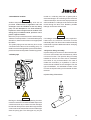
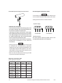
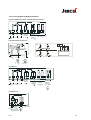
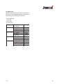
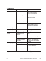
Operating instructions
Motor-Diaphragm Dosing Pumps
Types MEMDOS MR
Dosing
Conveying
Control
Liquids
Gases
Systems
Operating instructions
MEMDOS MR
Lutz-Jesco GmbH, 2003
Address:
Lutz-Jesco GmbH
Am Bostelberge 19
D-30900 Wedemark
PO Box 10 01 64
D-30891 Wedemark
Tel.: +49 (0) 51 30 58 02-0
Fax: +49 (0) 51 30 58 02 68
E-Mail: [email protected]
Internet: www.jesco.de
24h-Hotline:
+49 (0) 51 30 580 280
Content
1.
Safety ............................................................................................................................ 5-7
1.1 General ............................................................................................................ 5
1.2 Warnings used int this Operating Manual ......................................................... 5
1.3 Qualification and training of personnel .............................................................. 5
1.4 Hazards due to non-compliance with safety instructions .................................. 5
1.5 Safe operation .................................................................................................. 5
1.6 Safety instructions for the owner/operator ...................................................... 5-6
1.7 Safety instructions for inspection, maintenance and installation work .............. 6
1.8 Unauthorized modification and production of spare parts .................................. 6
1.9 Impermissible modes of operation .................................................................... 6
1.10 Dosing of chemicals ..................................................................................... 6-7
1.11 Scope of delivery ............................................................................................. 7
2.
General, purpose .............................................................................................................. 7
3.
Functional .......................................................................................................................... 8
4.
Technical data ................................................................................................................ 8-9
4.1 Technical data MEMDOS MR ........................................................................... 8
4.2 Electrical motor data ........................................................................................ 8
4.3 Technical data ATE-drives ................................................................................. 9
5.
Performance curves ........................................................................................................ 10
6.
Type codes ........................................................................................................................11
7.
Installation .................................................................................................................. 12-16
7.1 General notes of instruction ............................................................................ 12
7.1.1 Installation of MEMDOS MR with ATE-servomotor .................................. 12
7.2 Installation location ......................................................................................... 13
7.3 Drain pipe ....................................................................................................... 13
7.4 Injection fitting assembly ........................................................................... 13-14
7.5 Electrical connection ................................................................................. 14-15
7.5.1 Circuit diagram ATE-servomotors ............................................................ 15
7.6 Installation example ........................................................................................ 16
8.
Stroke length adjustment ............................................................................................... 16
9.
Start up ........................................................................................................................ 16-17
9.1 Start up of MEMDOS MR with ATE-servomotor ............................................... 17
10. Maintenance ............................................................................................................... 17-18
10.1 Lubrication .................................................................................................... 17
10.2 Maintenance of bearings ............................................................................... 17
10.3 Maintenance of ATE-servomotors (optional) .................................................. 17
10.3.1 Manual adjustment of the ATE-drive Type AR 30 W... ........................... 17
10.4 Replacing the diaphragm .............................................................................. 18
9.03
3
11. Explosion-proof dosing pumps ...................................................................................... 18
11.1 General ......................................................................................................... 18
11.2 Special conditions ......................................................................................... 18
11.3 Dosing of flammable media ........................................................................... 18
12. Spare parts ...................................................................................................................... 19
13. Troubleshooting .............................................................................................................. 20
14. Certificate of conformity ............................................................................................ 21-22
Hypalon® and Viton® are registered trademarks of DuPont Dow Elastomers
Teflon® is a registered trademark of the DuPont Company
Hastelloy® is a registered trademark of Haynes International, Inc
4
Technical changes are always reserved without notice.
9.03
1. Safety
1.1 General
This Operating Manual contains basic information
to be noted during installation, operation and
maintenance. It is therefore essential that the Manual
be read by the fitter before installing and
commissioning the pump/system, as well as by the
relevant operating personnel / owner of the pump/
system. It must remain accessible at the pump/
system for reference at all times.
In addition to the general safety instructions set out
under this main heading Safety, the special safety
precautions set out under the other main headings
must also be observed, for instance in conjunction
with private use.
1.2 Warnings used in this Operating Manual
This Operating Manual contains warnings which may
endanger persons, the environment and the pump/
system if they are disregarded. These warnings are
identified by the hazard symbol
safety mark in accordance with DIN 4844-W9
The following symbol is used in conjunction with
electric power
safety mark in accordance with DIN 4844-W8
The word
Caution
appears in conjunction with safety instructions
which may endanger the machine and its operation
if disregarded.
Markings which are affixed directly to the pump,
such as
- Direction of rotation arrow
- Markings for fluid connections
must be observed without fail and must remain fully
legible at all times.
9.03
Note
Draws attention to supplementary information to
make the work easier and ensure troublefree
operation.
1.3 Qualification and training of personnel
The personnel employed for operation, maintenance,
inspection and installation must be suitably qualified
for this work. The areas of responsibility, competence
and supervision of the personnel must be precisely
defined by the owner. Personnel who do not have
the requisite know-how must be duly trained and
instructed. If necessary, this can also be undertaken
by the manufacturer/supplier on behalf of the pump’s
owner. In addition, the owner must also ensure that
the relevant personnel are fully familiar with and have
understood the contents of the Operating Manual.
1.4 Hazards due to non-compliance with the
safety instructions
Failure to comply with the safety instructions may
endanger not only persons, but also the environment
and the pump/system. Non-compliance with the
safety instructions can lead to the loss of all
entitlement to damages.
The following hazards in particular may arise:
- Failure of major pump/system functions.
- Failure of specified methods for maintenance and
repair.
- Danger to persons due to electrical, mechanical
and chemical effects.
- Danger to the environment due to leakage of
hazardous substances.
1.5 Safe operation
The safety instructions contained in this Operating
Manual must be observed. The owner is responsible
for ensuring compliance with local safety regulations.
1.6 Safety instructions for the owner/operator
- If hot or cold machine parts are a source of danger,
precautions must be taken by the customer to
prevent contact.
- Guards on moving parts must not be removed when
the machine is in operation.
5
- Leakages (e.g. at the shaft seal) of hazardous
substances (e.g. explosive, toxic, hot substances)
must be discharged in such a way as to exclude
all danger to persons and the environment.
Statutory regulations must be observed.
- Danger due to electric power must be excluded
(for further details, refer to the VDE regulations and
the regulations of the local public utilities).
- Separate regulations must be observed if the dosing
pumps are operated in explosion-hazard areas. The
explosion hazard must be defined (classification
of zones) and appropriate equipment selected by
the owner. Further information can be found in
section 7.1 (Installation), section 7.5 (Electrical
connection) and section 11 (Explosion-proof dosing
pumps).
1.8 Unauthorized modification and production
of spare parts
The machine may only be modified or converted in
consultation with the manufacturer. Genuine spare
parts and accessories authorized by the
manufacturer ensure greater safety. Liability for
damage or loss may be extinguished if other parts
are used.
1.7 Safety instructions for inspection,
maintenance and installation work
The owner must ensure that all maintenance,
inspection and installation work is undertaken by
authorized and duly qualified skilled personnel who
have also studied the Operating Manual in depth.
The pump must always have come to a complete
stop before starting any work on the pump. The
procedure specified in the Operating Manual for
shutting down the pump/system must be observed
without fail.
Pumps or units in contact with potentially harmful
media must be decontaminated.
All safety mechanisms and guards must be refitted
and reactivated as soon as the work is complete.
1.10 Dosing of chemicals
Particular care must be taken when repairing dosing
pumps which are used in explosion-hazard areas.
Due to the risk of sparking, care must be taken to
prevent metal parts or tools knocking against one
another. The dosing pump should preferably be
moved out of the explosion-hazard area in order to
be repaired.
The points set out in the section Installation and
commissioning must be observed before starting the
pump/system.
6
1.9 Impermissible modes of operation
The operational safety of the pump supplied can
only be guaranteed when it is used in conformity
with its intended use as specified in our contract
documents, especially the letter confirming the
order. The limit values specified in these documents
must never be exceeded.
- When working on dosing installations, the local
safety rules must be observed (e.g. wear personal
protective clothes).
- Before working on the dosing pump and plant,
disconnect it from the mains supply and protect it
against reconnection. Before the power supply is
switched on again, the dosing lines must be
connected so that any chemical left in the dosing
head cannot spurt out.
- The dosing head of the pump as well as connections
and lines of the plant may be under pressure.
Working on the dosing plant requires special safety
precautions and may only be carried out by
instructed technical personnel.
- Before startup, all screwed connections must be
checked for correct tightness and, if necessary,
must be tightened up using appropriate tools.
- If connections at the dosing head are unscrewed
during operation for venting or other reasons, leaking
chemical must be removed professionally. This is
the only way to avoid the danger of physical injury
and corrosion at the dosing pump. Leaking chemical
might also destroy the diaphragm at its mounting
points.
Technical changes are always reserved without notice.
9.03
- When changing the chemical, check whether the
materials used for the dosing pump and the other
plant parts are chemically resistant. If there is the
danger of a chemical reaction between different
media, a thorough cleaning first is mandatory.
- To operate the pump mount the fan shell in order
to ensure sufficient cooling of the motor.
- Adjustment works in the interior of the ATE drive
(optional) must be carried out carefully. Connections
and internal limit switches might be "alive".
- Additional limit switches might be "alive" even with
the auxiliary voltage switched off (ATE-drive).
- After installation works at the ATE servomotor or
before startup remount the cover.
1.11 Scope of delivery
Note
Please unpack the dosing pump and ordered
accessories carefully in order not to miss small parts.
Immediately compare the scope of delivery to the
delivery note. If there are any discrepancies, try to
find out the reason.
For the transportation of the dosing pumps, no
special fittings are required. It is, however, advisable
to choose a transportation method, which is
appropriate for the weight of the dosing pumps (e.g.
wagon). During transportation without oil, the dosing
pump should be lying. Otherwise it must be
tightened to the transportation device.
9.03
2. General, purpose
Motor-driven diaphragm dosing pumps of series
MEMDOS MR/ZMR are used in industry, in process
engineering and in water and wastewater processing.
Standard versions are dosing pumps with the head
located on the left-hand side. (MR...L)
Versions with the head on the right-hand side can
be supplied. ( MR...R)
MEMDOS ZMR pumps are tandem dosing pumps
with two dosing heads of equal size or combinations
of different dosing heads (ZMR.../...). The power of
the motor is the same for simplex and duplex dosing
pumps because the diaphragms operate in a pushpull arrangement.
- If no control is required for constant metering, the
motor is connected directly to the terminal box.
In this case, MEMDOS MR/ZMR pumps are used.
Three-phase and a.c. motors are available. To
change the dosing capacity, either the stroke
length can be adjusted from 0 to 100% or the
speed of the three-phase motor can be controlled
by means of a separate frequency converter.
- The MEMDOS MR/ZMR is optionally available with
electrical remote adjustment (ATE) allowing the
dosing pump to be used as actuator in control
loops. The stroke length is adjusted via
momentary contacts or controllers with relay
output. In the case of duplex pump MEMDOS
ZMR, each head may be fitted with a separate
servomotor and adjusted independently.
- Upon request, also „increased safety“-type or „airtight“ servomotors can be supplied.
7
3. Functional
The gear contains a single-stage worm wheel set
runing in an oil bath just as the roller bearings. Dosing
happens while the push rod is displaced by means
of an eccentric. The suction stroke is caused by the
resetting of the spring. The stroke length is adjusted
by limiting return travel of the poppet using a
manually adjustable eccentric as stop. An
adjustment range from 0 to 100% is possible.
4. Technical data
4.1 Technical data MEMDOS MR
Simplex dosing pumps
MEMDOS MR
400
max. pressure bar
600
980
5
5
4
at max.
l/h
440
640
990
pressure
ml/Hub
165
165
165
47
70
101
diaphragm ø
mm
185
185
185
weight
kg K.-St
38
38
38
E.-St
48
48
48
strokes/min
Duplex dosing pumps with equal heads
MEMDOS ZMR
50/50
max. pressure bar
75/75
115/115
140/140
210/210
290/290
400/400 600/600 980/980
10
10
10
10
10
10
50/50
90/90
135/135
160/160
240/240
290/290
ml/Hub
20
20
20
37
37
48
47
70
101
70
101
101
47
70
101
diaphragm ø
mm
90
90
90
120
120
150
185
185
185
weight
kg K.-St
38
38
38
38
38
40
50
50
50
E.-St
48
48
48
48
48
53
60
60
60
at max.
l/h
pressure
strokes/min
5
5
4
440/440 640/640 990/990
165
165
165
Duplex dosing pumps with different heads
MEMDOS ZMR
50/400
75/140
75/600
115/210
max.pressure bar
10
10 10
10
10
at max.
l/h
55 440 90 160 90 640 135 240 135 290 135 990 160 640 240 290 240 990 290 990
pressure
ml/Hub
20 165 20 37
strokes/min.
47
diaphragmø mm
weight
5
70
5
20 165 20
70
115/290
10 10
10
37 20
101
48
115/980 140/600 210/290 210/980
290/980
10
10
4
10
5
10
20 165 37 165 37
101
101
90 185 90 120 90 185 90 120 90 150
70
10
48
101
10
4
4
37 165
48 165
101
101
90 185 120 185 120 150 120 185 150 185
kg K.-St
49
38
49
38
40
41
41
40
49
49
E.-St
55
48
55
48
53
55
55
50
55
55
4.2 Electrical motor data
Elect. motor
Part
Circuit
Voltage
Current
Type
No.
V
consumption A
AF 80 / 4A-11 78629
∆ Y
230/400
2.6 / 1.55
AF 80 / 4B-11
78903
∆ Y
230/400
3.5 / 2.0
AF 80 / 4B-11 78982*
∆ Y
230/400
3.5 / 2.0
* Motor fitted with cold-conductor thermometer probe
8
Power
kW
0.55
0.75
0.75
Speed
1/min
1390
1400
1400
Frequency
Prot. class
Hz
ISO cl.
IP
50
F
55
50
F
55
50
F*
55
Technical changes are always reserved without notice.
9.03
4.3 Technical data ATE-drives
Types AR 30W23 and AR 30W23S
Type
AR 30W..
Design
Reversible a.c. motor with self-locking reduction gear
Use
for controllers with switching
output (3-point control)
230V~ ± 15%
50...60 Hz
Auxiliary voltage
Control
Power consumption
Regulating time/bevel
Position repeating signaling
for remote display
Limit switch
Protection class
Ambient temperature
Options
2nd potentiometer
Limit switches (2 off)
2W
360s / 270° = 0...100%
Potentiometer 0.5 W
0...1000 Ω = 0...100%
Internal limit switches for
limiting angle of rotation.
Signaling of final position via
terminals 16 and 17
IP 55 (EN 60529)
-20 ... 60°C
AR 30W..S
for controllers with continous
output (2...10V or 4...20mA)
24V ~ ± 20%
50...60 Hz
2...10V or 4...20mA
7W
0...620mV = 0...100%
Internal limit switches for
limiting angle of rotation.
0...1000 Ω 0.5 W
max. 250V 1A
Types WAN 1 and WAN 1-S
Type
WAN 1
Design
Reversible a.c. motor with self-locking reduction gear
Use
for controllers with switching
output (3-point control)
230V~ ± 10% 50...60 Hz
Other voltages upon request
Auxiliary voltage
Control
Power consumption
Regulating time/bevel
Position repeating signaling
for remote display
Limit switch
Protection class
Ambient temperature
Options
2nd potentiometer
Limit switches (2 off)
9.03
WAN 1-S
for controllers with continuous
output 0(4)...20mA
230V~ ± 10% 50...60Hz
0(4)...20mA
approx. 11.5 W
360s / 270° = 0...100%
Potentiometer 0.5 W
0(4)...20mA (as an option only)
0...1000 Ω = 0...100%
Internal limit switches for limiting the angle of rotation.
Signaling of the final position via terminals 4 and 5
IP 54 according to DIN 40050
max. 60°C
0...1000 Ω 0.5 W
max. 250V 1A
9
5. Performance curves
run with water, suction lift approx. 0.5 m
l/h MR 50
1bar
70
5bar
10bar
60
50
40
30
20
10
0
1
2
3
4
5
6
7
8
9
l/h MR 75
1bar
5bar
10bar
100
90
80
70
60
50
40
30
20
10
10
0
1
2
3
4
Scale
1bar
5bar
10bar
l/h MR 115
140
120
100
80
60
40
20
0
1
2
3
4
5
6
Scale
7
8
9
8
9
10
l/h MR 140
0
1bar
5bar
10bar
1
2
3
4
5
6
Scale
7
8
9
10
l/h MR 290
350
1bar
400
300
5bar
350
250
10bar
300
1bar
5bar
10bar
250
200
200
150
150
100
100
50
0
7
200
180
160
140
120
100
80
60
40
20
10
l/h MR 210
5
6
Scale
50
1
2
3
4
5
6
7
8
9
10
0
1
2
3
4
Scale
5
6
7
8
9
10
Scale
l/h MR 400
l/h MR 600
1bar
3bar
5bar
800
600
1bar
3bar
5bar
500
400
700
600
500
400
300
300
200
200
100
0
100
1
2
3
4
5
6
Scale
7
8
l/h MR 980
10
1
10
1bar
1100
1000
900
800
700
600
500
400
300
200
100
0
9
2
3
4
5
6
Scale
Skala
7
8
9
0
1
2
3
4
5
6
Scale
7
8
9
10
2bar
3bar
4bar
10
Technical changes are always reserved without notice.
9.03
9.03
1
number of dosing heads
1-Simplex pump
2-Duplex pump
MATCH-CODE
0 1 0 5
material
P - PP
Nominal size
MR 400
MR 600
MR 980
0400
0600
0980
Capacity
Discharge
connection
(other electrical data)
A.C. motor with starting
For order example and explanation see general "MATCH CODE SYSTEM" page.
Frames indicate the standard version, e.g.:
and operating capacitor)
Z - Special drive
V - 230/50/55/F
Type of circuit S 604 (especially rewound
Z - Special connection
X - DN 25, PN 16
E Ex de ll C T4
A.C. motor
Flanged connection
explosion-proof, air-tight
O - 400/50/55/F
P - G 3/4 MR 400 only
Q-G1
B - 400/50/55/F
M - d 40
L - d 32
Cemented connection
H - d 25 MR 400 only
Hose liner
Suction
connection
Threaded connection
9 - Special valve
6 - Viton
5 - Hypalon
with seals made of:
single ball valves
Spring-loaded
Suction valve
Discharge valve
Three-phase motor 0.75 kW
A - 400/50/55/F
Three-phase motor 0.55 kW
Electrical
drive
N - 400/50/55/F
P - PP
Z - Special adj.
E - ATE adj.
M - Man. adj.
adjustment
explosion-proof, increased safety E Ex e ll T3
material
Z - Special
1.4571
S - St. steel
Head
Capacity/
6. Type codes
11
7. Installation
7.1 General notes of instruction
For the selection of a dosing pump when designing
a plant as well as for the installation and operation,
the local rules must be observed. This applies to
the selection of suitable pump materials, the handling
of the chemicals and the electrical installation.
Before installing the pump in explosion-hazard
areas, the dosing pump must be checked to ensure
that it meets with the minimum requirements
imposed by the applicable explosion protection
regulations. For this purpose, the data on the rating
plate of the dosing pump must be compared with
the local requirements.
At the same time the technical data of the dosing
pump (see chapter 4) must be taken into
consideration, and the plant must be designed
correspondingly (e.g. pressure loss in lines
depending on nominal diameter and length).
Note
The designer and the user are responsible to make
sure that the whole plant including the dosing pump
is constructed so that neither plant equipment nor
buildings are damaged serverely in the case of
chemical leakage due to the failure of wear parts
(e.g. diaphragm rupture) or burst tubing. If the
chemical plant represents a potential source of
danger, the installation must be carried out so that
no unreasonably high consequential damages occur
even if the dosing pump fails. Therefore we
recommend to install leakage probes and
containment tanks.
Dosing pumps are produced according to highest
quality standards and have a long service life.
Nevertheless some parts are subject to wear (e.g
diaphragm, valve seats, valve balls). To ensure long
operating life, visual checks are required regularly.
Operating and maintenance personnel must be able
to access the pump easily. Periodic maintenance
protects the dosing pump against shutdowns.
12
To increase the dosing accuracy and to ensure the
functional reliability, we recommend to use additional
fittings. These include backpressure valves, relief
valves, leakage probes, low level indicators and
especially pulsation dampers to prevent pressure
surges, as shown in the installation examples
(chapter 7.6).
Always use appropriate tools for the installation of
plastic connecting parts. To avoid damage, never
apply excessive force. Plast parts (especially PVC
parts) can be screwed and unscrewed more easily
if the thread is lubricated with silicone grease before.
Note
For this purpose, the compatibility with the chemical
to be metered must be checked.
7.1.1 Installation of MEMDOS MR with ATEservomotor
The ATE servomotor is connected to the pump and
adjusted in the factory.
For installation a sufficient mounting space of at least
150 mm must be provided for later maintenance
works.
The electrical connection of the ATE drive must
correspond to the local rules and may only be carried
out by technical personnel.
The circuit diagrams (chapter 7.5.1) show the two
basically realizable possibilities of connection.
Cable type and cable cross section must be chosen
according to the motor data.
The cable passage to the motor terminal box must
be made professionally. We recommend gland
screw connections with traction relief.
The required protection class must be ensured by
professional installation of the electrical
connections.
Caution
Please take into account that the ATE drive can only
be controlled with the main motor running, i.e.: the
ATE drive must be locked electrically. Otherwise the
adjusting eccentric wears out frequently or is
destroyed.
Technical changes are always reserved without notice.
9.03
7.2 Installation location
Caution
Ambient temperatures exceeding 40°C are not
permitted. Radiant heat of apparatus and heat
exchangers must be shielded so that the dosing
pump can still dissipate its own heat sufficiently.
Exposure to direct sunlight must be avoided. If the
dosing pump is installed outside, provide a roof to
protect it against weather.
Mount the pump so that the suction and discharge
valve are in vertical position. To ensure that the pump
stands firm, fasten it with screws on an appropriate
foundation.
The system piping must not exert any force on the
connections and valves of the metering pump. To
avoid incorrect metering after the process is finished,
provide an electric and hydraulic interlocking system.
7.3 Drain pipe
routed to a collecting tank free of gases (with a
downward slope) or to a collecting funnel - also with
a downward slope - above which the pipe ends at a
sufficient distance. Leakage can be returned via the
funnel through the tank cover. Besides, possible
leakage can be seen at the funnel.
Caution
If a leakage monitor is installed in the explosionhazard area, the electrical connection must be
intrinsically safe. The drive motor must be electrically
interlocked to prevent additional medium escaping
if a leak occurs.
7.4 Injection fitting assembly
Injection fittings are used to mix the metered medium into a main stream and simultaneously fulfil a
non-return function. The injection fitting is usually
installed in the main line from above. Installation
from below is only recommended in the case of
media with a tendency to crystallize, in order to
ensure that air bubbles are not entrapped. For this
type of installation, it is advisable to select a form
in which the injection fitting can be sealed off when
removed.
Injection fitting S from above:
Caution
Drainage or leakage from the separating chamber
must be routed with a certain downward slope to the
containment tank. By no means must the drain pipe
be returned directly to the chemical through the tank
cover because otherwise effervescent media might
enter the pump gear. The drain pipe may only be
9.03
13
Extractable injection fitting from down below
Circuit diagram of the drive motor
Caution
To avoid early wear of the gear drive adhere to the
correct rotation direction of the motor by all means:
looking at the fan wheel, counterclockwise.
- 3-phase supply
7.5 Electrical connection
- The electrical connection of the dosing pump must
be made according to the local rules and may only
be carried out by technical personnel.
- Cable type und cable cross section of the supply
lines must be selected according to the motor data.
- The cable passage to the motor terminal box must
be made professionally. We recommend gland
screw connections with traction relief.
- The required protection class must be ensured by
professional installation of the electrical
connections.
Caution
Dosing pumps with explosion-proof motors must
be installed and commissioned by specialists
qualified to work with equipment destined for use
in potentially explosive atmospheres. The user is
responsible for ensuring that the explosion-proof
motors are connected correctly.
- Both the motor and the pump must be grounded
to prevent electrostatic discharges.
L1
W2
U2
V2
W2
U2
V2
U1
V1
W1
U1
V1
W1
L2
L3
Y-connection
PE
L1
L2
L3
PE
D-connection
- Special versions
For other special versions please refer to the
corresponding separate circuit diagrams.
Electrical connection data
(other types upon request)
Pump
model
MR 50
... MR 980
MR 50
...MR 980
MR 50
...MR 980
MR 50
...MR 980
MR 50
...MR 980
MR 50
...MR 980
14
Voltage
[Volt]
400/230
50 Hz
400/230
60 Hz
440/254
60 Hz
400/230
50 Hz
400/230
60 Hz
440/254
60 Hz
Power
[kW]
0.55
Current
[A]
1.50/2.60
0.55
1.25/2.20
0.55
1.25/2.20
0.75
2.00/3.50
0.75
1.75/3.05
0.75
1.70/310
Technical changes are always reserved without notice.
9.03
7.5.1 Circuit diagram for ATE-servomotors
Type AR 30W23 F001 230V~ and AR 30W23 F020 24V~
HE
E
HA
A
16 2
1
PE Open
3 17
N
10 11 12
Position
repeating
signaling
0...1 k
Close
230V
13 14 15
4 5 6 7 8 9
O p t i o n a l
Position
repeating Voltage-free contacts
1A
max. 250V
signaling
0...1 k
Type AR 30W23S F020 24V~
S4
M
1 2
3
S5
4
24V
4 ... 20mA
0 ... 10 V
0 ... 620mV
0 Ö 10 V
Type WAN 1
E
PE
A
4 2
1
3 5
Open
N
Close
18 19 20
Position
repeating
signaling
1 k
230V
21 22 23
6 7 8 9 1011
29303132
O p t i o nal
Position
repeating
signaling
1 k
Voltage-free
contacts
max.250V
1A
Position
repeating
signaling
0(4) ... 20mA
Type WAN 1-S
M
L N
OPEN
CLOSE
230V
4 5
515253
Conductance
0(4) Ö 20mA
Final position
Repeating signal
9.03
15
7.6 Installation example
6
2
8
5
4
7
3
1
8. Stroke length adjustment
Caution
The stroke length must not be adjusted when
the pump is at a standstill !
Proceed as follows to adjust the stroke length:
1. Turn the screw securing the adjusting knob
anticlockwise (to the left) to release it.
2. Set the stroke length to the required value in
accordance with the delivery characteristics
(chapter 5).
3. Retighten the screw without changing the set
stroke length.
9. Start up
1. Before starting the dosing pump all works
mentioned in "Installation" (chapter 7) must be
carried out. Fill the pump with the oil supplied. At
the same time the safety instructions must be
observed.
2. The dosing pump is switched on by a control to
be installed externally.
3. The manual or electrical capacity adjustment must
be set to maximum stroke to improve priming.
During first priming no backpressure should be
applied. For this purpose we recommend to install
a relief valve on the discharge side of the dosing
pump.
16
Explanation:
1 MEMDOS MR
2 Electric agitator
3 Chemical tank
4 Relief valve
5 Diaphragm shutoff valve
6 Injection fitting
7 Pulsation dampener
8 Backpressure valve
4. A previously installed priming aid must be filled
with chemical first. If the pump is not priming,
remove the discharge valve and fill water or
chemical (if not dangerous!) into the dosing head.
Remount valve and start priming.
5. If a venting facility is available as separate unit,
open it and wait until liquid escapes. Then close
it again. In the case of effervescent liquids allow
the liquid to escape permanently (approx. 1 drop
for 1...3 strokes).
6. When correct operation is achieved, set to
required output by means of the adjusting knob
(refer to chapter 8) or the electrical remote
adjustment. For approximation refer to the
performance curves (chapter 5). Depending on the
installation and the chemicals used, these values
may differ and must be checked under operating
conditions.
7. The manufacturer of the metering equipment is
not responsible for damages due to excessive or
low flow rates resulting from faulty pump settings
or incorrect and insufficient installation of
peripheral fittings.
Technical changes are always reserved without notice.
9.03
9.1 Start up of MEMDOS MR with ATEservomotor
Switch on the main drive motor of the metering pump.
With an electrical interlocking system, only then can
the ATE drive be adjusted.
To check the direction of rotation send short control
pulses to the ATE servomotor.
If the direction of rotation is wrong, the supply lines
(terminals 2 and 3 in the case of direct controls) are
reversed.
The ATE servomotor must be moved to the final
positions in order to check the limit stop mechanism
of the integrated limit switches. When leaving the
factory, the angle of rotation is 270°. If required, the
angle of rotation and thus the maximum flow rate
can be restricted. To achieve this, the upper trigger
cam is shifted by the required value.
10. Maintenance
10.1 Lubrication
The diaphragm dosing pump MEMDOS MR requires
little maintenance. The gear of the pump is lubricated
with gear oil of viscosity class ISO-VG 460 according
to DIN 51519 (corresponds to SAE 140 according to
DIN 51512). The enclosed first filling must be renewed
after approximately 500 operating hours. Further oil
changes should be carried out every 5,000 operating
hours. The filling capacity is about 0.75 l for simplex
gears and about 0.9 l for duplex gears. The actually
required quantity of gear oil can be determined by
reading the oil gauge; the oil should cover half of the
oil gauge.
10.2 Maintenance of bearings
The upper bearing of the pinion shaft is a sealed
and permanently lubricated ball bearing. The other
rolling bearings in the gearbox and the plain bearings
of the diaphragm rod are lubricated by the gear oil.
The oil also dissipates the heat generated.
All bearings must be examined for wear after 5000
hours of operation. The service life of the rolling
bearings depends on the loads to which they are
subjected. The bearings must be replaced after 5000
hours of operation if the dosing pump is operated at
maximum load.
10.3 Maintenance of ATE-servomotor (optional)
The ATE servomotor is lubricated for life before leaving
the factory. Nevertheless regular checks are
recommended if the drive works under difficult
operating conditions, such as a high ambient
temperature or continuous operation. For
relubrication of the ATE gear use molybdenum
disulfite, e.g. "Molykote BR2plus" and "OKS400".
10.3.1 Manual adjustment of the ATE-drive Type
AR30W...
In the case of an electrical failure of the ATE
servomotor type AR30W, it can be adjusted manually
by means of a hand crank. This part is available as
accessory (Part No. 32.587).
For manual adjustment proceed as follows:
1. Switch off power supply to the ATE servomotor.
2. Remove ATE cover.
3. Switch on main drive motor.
4. Insert hand crank in corresponding opening, as
shown below, and turn into desired direction.
Caution
The final positions must not be crossed !
5. After manual adjustment remount the cover.
Insert hand crack and turn
3
1
2
Setting of angle of rotation
span
span
span= 90˚
9.03
3.05
17
10.4 Replacing the diaphragm
In the case of a rupture the diaphragm can be
replaced as follows:
1. The chemical contained in the metering line is
drained so that the metering lines become
pressureless. Please observe the
aforementioned safety instructions for this
purpose.
2. The flow rate of the metering pump is set to zero
while the motor is running. Thus the diaphragm
is moved to its front end position.
3. The head is removed using an appropriate tool.
4. Grasped at the edge, the diaphragm can now be
turned out counterclockwise.
5. Before installing the new diaphragm the
diaphragm flange section must be cleaned of
the chemical. Otherwise the diaphragm might
be attacked from the rear side.
6. The new diaphragm is turned in clockwise until
it sits close (grease screw thread).
7. The stroke adjustment is now set to maximum
while the motor is running.
8. Now the head is remounted by tightening it
carefully with the screws.
Screws must be tightened crosswise, e.g. top
left – bottom right – top right – bottom left. The
diaphragm is not properly sealed if the tightening
torque is too low. If it is too high, the dosing
head will be damaged. Required tightening
torque for dosing head screws:
Diaphragm-Ø Torque +/- 10%
90
6 Nm
120
6 Nm
150
10 Nm
185
12 Nm
9. After connecting the metering lines, the pump
is started as described in chapter 9, startup.
10. If the diaphragm wear is excessively high, try
to find out the reason. For this purpose, please
refer to chapter 13 Troubleshooting.
18
11. Explosion-proof dosing pumps
11.1 General
The MEMDOS MR explosion-proof dosing pump is
a motor-driven, explosion-proof diaphragm dosing
pump of equipment category 2, group II.
In combination with an explosion-proof motor (Ex II
2 G E Ex e II T3 or Ex II 2 G E Ex d/de IIB/IIC T4) it
is used to meter liquids in potentially explosive
areas of zone I. The pump bears the Ex identification
”Ex II 2 G c k T4 03 ATEX D086".
Caution
The pump must not be used to meter gaseous media
or solids.
11.2 Special conditions
Compliance with the minimum requirements for the
zone classification must be ensured when using the
dosing pump in potentially explosive areas. Both
the pump itself and the motor must meet with the
minimum requirements.
11.3 Dosing of flammable media
All metal parts in the intake and delivery piping must
be grounded to prevent electrostatic discharges
when dosing explosive liquids.
Stainless steel is recommended for the dosing head.
Dosing pumps with diaphragms measuring more
than 90 mm in diameter are equipped with special
conductive diaphragms to prevent static charging.
Only the original diaphragm may be fitted when
ordering replacement parts.
Technical changes are always reserved without notice.
9.03
12. Spare parts
Genuine spare parts from Lutz-Jesco must be used.
Wear parts for the MEMDOS MR are available as a
set of spare parts containing the following:
- Pump diaphragm
- Valve balls
- Valve seats
- all valve seals
Pump Type
Dosing head-/
seal material
MR 50...115
PP / Hypalon®
PP / Viton®
1.4571 / AF
MR 140...210 PP / Hypalon®
PP / Viton®
1.4571 / AF
MR 290
PP / Hypalon®
PP / Viton®
1.4571 / AF
MR 400...980 PP / Hypalon®
PP / Viton®
1.4571 / Hypalon®
1.4571 / Viton®
9.03
Part No.
25411
25423
25435
25412
25424
25436
25413
25425
25437
34504
34505
34506
34507
19
13. Troubleshooting
TYPE OF FAULT
POSSIBLE CAUSE
RECOMMENDED ACTION
Pump not delivering.
Valves leaking.
Clean and remove air from valves.
(See also startup of pump).
Tighten screw connections.
Valves incorrectly installed.
Reassemble valves. Ensure
that the valve balls of suction
and discharge valve are located
above the valve seats.
Suction filter, foot valve or
suction pipe leaking or
blocked.
Clean and seal suction line.
No stroke movement.
Return spring broken. Replace
spring. Consider density of the
chemical! Suction lift too high.
Pump delivering too
little or irregularly.
Valves blocked or leaking.
Clean and re-seal valves.
Pump delivering too
much.
Pressure on suction side too
high (pump siphoning).
Install backpressure valve in
discharge line.
Frequent diaphragm
ruptures.
Diaphragm was not screwed
into diaphragm rod as
far as stop.
Screw in new diaphragm as far as
stop.
Injection nozzle blocked.
Clean injection nozzle; fit larger one,
if necessary.
Pressure peaks because
metering line is too long
or too narrow.
Change line or install pulsation
dampener. For increased safety
install relief valve (see installation
example).
Roller bearing defective.
Replace roller bearing.
No or little oil in gearbox.
Refill oil, as described
in section "maintenance".
Wrong connection.
Check electrical wiring.
Pressure too high.
Check process.
Pump very noisy.
Motor hums and doesn't
start.
If the problem cannot be corrected on the basis of the above data, return the pump to the factory or contact our
Technical Sales Service for further measures. Repairs will be carried out immediately.
20
Technical changes are always reserved without notice.
9.03
14. Certificate of conformity
EC – Declaration of Conformity
We,
Lutz-Jesco GmbH
Am Bostelberge 19
D – 30900 Wedemark
hereby certify
that the product described in the following complies with the relevant fundamental safety
and sanitary requirements and the EC regulations mentioned below due to the concept
and design of the version sold by us.
If the product is modified without our consent, this declaration loses its validity.
Product description:
Diaphragm Dosing Pump
Model designation:
Minidos A, Memdos TM, Memdos M, Memdos ML,
Memdos E, Memdos MR., Memdos GMR
Relevant EC regulations:
EC Low-Voltage Directive (73/23/EEC)
EC Directive Relating to Machinery (89/392/EEC)
amended by 93/44/EEC
Applied harmonized
standards, especially:
EN 292 – 1 and EN 292 – 2, Safety of Maschines
prEN 809, Pumps and Pump Devices for Liquids,
Safety Requirements
Date, Signature of Manufacturer: 2003/02/02 . . . . . . . . . . . . . . . . . . . . . . . . . .
Information on the signer:
Mr. Lucjan Gogolin, Head of Technical Office
This declaration is no assurance of characteristics in the sens of the product liability law.
The safety notes in the operating instructions must be observed.
9.03
21
EC – Declaration of Conformity
We,
Lutz-Jesco GmbH
Am Bostelberge 19
D – 30900 Wedemark
hereby certify
that the product described in the following complies with the relevant fundamental safety
and sanitary requirements and the EC regulations mentioned below due to the concept
and design of the version sold by us.
If the product is modified without our consent, this declaration loses its validity.
Product description:
Explosion proofed Diaphragm Metering Pump
Model designation:
Memdos E, Memdos MR
Relevant EC regulations:
EC Low-Voltage Directive (73/23/EEC)
EC Directive Relating to Machinery (98/37/EC)
EC Directive for Equipment and protective systems
intended for use in potentially explosive atmospheres
(94/9/EC)
Applied harmonized
standards, especially:
EN 292–1 and EN 292–2, Safety of Maschines
EN 809, Pumps and Pump Devices for Liquids,
Safety Requirements
EN 13463–1, Non-electrical equipment for potentially
explosive atmospheres
Date, Signature of Manufacturer: 2003/07/01 . . . . . . . . . . . . . . . . . . . . . . . . . . . . .
Information on the signer:
Mr. Lucjan Gogolin, Head of Technical Office
This declaration is no assurance of characteristics in the sens of the product liability law.
The safety notes in the operating instructions must be observed.
22
Technical changes are always reserved without notice.
9.03