1
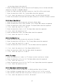
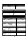
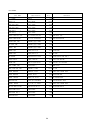
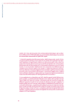
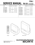
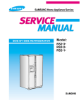
SERVICE MANUAL
MODEL FG-8110
SWEEP/FUNCTION GENERATOR
CONTENTS
1. PERFORMANCE CHECK
PROCEDURE
2. ADJUSTMENT PROCEDURE
3. TROUBLESHOOTING PROCEDURE
4. PARTS LIST
5. CIRCUIT DIAGRAM
2
1. PERFORMANCE CHECK PROCEDURE
1-1. General
This section contains the Procedures required to check and maintain specified instrument
performance. The adjustments should be performed at an ambient temperature of
23°C ±5°C and a relative humidity of less than 60%. It allows the instrument to stabilize at
this environment for a minimum of 30 minutes.
1-2. Equipment's required
Table 1-1 is shown test equipment's required.
Table 1-1 Equipment's required
No
.
Equipment name
Specification
1.
Frequency Counter
DC to 60 MHz
2.
Oscilloscope
DC to 20 MHz
3.
AC Millivolt Meter
Up to 30 Vrms
4.
Distortion Analyzer
0.01% 100kHz
5.
DC Power Supply
DC 0 to 10V
6.
Signal Generator
200mHz to 110 MHz
7.
FEEDTHROUGH TERMINATION 50 Ω
1-3. Performance check
1-3-1. OUTPUT FREQUENCY RANGE
SPECIFICATION
0.1 Hz TO 10 MHz
ACCURACY
+/- 5 % OF SETTING
EQUIPMENT
FREQUENCY COUNTER
BNC CABLE
FEEDTHROUGH TERMINATION 50 Ω (if necessary)
PROCEDURE
2. Set 8210 as follows;
3
Remark
- Function ; SINE WAVE (
)
- ATT
; 0 dB(PULL OUT)
- AMPLITUDE ; CENTER
- COUNT
; INT(PULL OUT)
- DC OFFSET ; OFF(PUSH IN)
- SYM
; OFF(PUSH IN)
- SWEEP
; OFF(PUSH IN)
2. Connect the frequency counter to output terminal.
3. Set the frequency counter to frequency measurement.
4. Set the output frequency of this product by FREQUENCY RANGE and DIAL and verify
counter frequency reading as follows;
8210 setting
Range
Frequency
1M
10.000 MHz
100.00 kHz
100k
1.0000 MHz
10.000 kHz
10k
100.00 kHz
1.0000 kHz
1k
10.000 kHz
100.00 Hz
100
1.0000 kHz
10.000 Hz
10
100.00 Hz
1.0000 Hz
1
10.000 Hz
100.00 mHz
Counter reading
** For reading less than 200 mHz, you can read by period value.
200mHz ; 5.000 sec
100 mHz ; 10.000 sec
1-3-2. AMPLITUDE AND ATTENUATION
SPECIFICATION
Amplitude range
;100mVp-p to 10Vp-p IN TO 50Ω
Attenuation
;20 dB
ACCURACY
Lower than 100mVp-p(IN TO 50Ω) at MIN.
Higher than 10Vp-p(IN TO 50Ω) at MAX.
4
EQUIPMENT
Oscilloscope
AC Millivoltmeter
BNC CABLE
FEEDTHROUGH TERMINATION 50 Ω
PROCEDURE
1. Set this product as follows;
- Function ; SINE WAVE (
)
- ATT
; 0 dB(PULL OUT)
- AMPLITUDE ; CENTER
- COUNT
; INT(PULL OUT)
- DC OFFSET ; OFF(PUSH IN)
- SYM
; OFF(PUSH IN)
- SWEEP
; OFF(PUSH IN)
2. Connect the oscilloscope through FEEDTHROUGH TERMINATION 50 Ω
to output terminal.
3. Set Amplitude Control to Min. position and check the output level is lower than
100mVp-p(less 5div in 20mV/div).
4. Set Amplitude Control to Max. position and check the output level is higher than
10Vp-p(higher than 4div in 5V/div).
5. Set Amplitude Control to Min. position and connect AC Millivoltmeter to output
terminal.
6. Set the Range of AC millivoltmeter to 3V range and adjust Amplitude control for
0dB reading on AC millivoltmeter.
7. Push in “20dB ATT switch” and check the reading of AC Millivoltmeter is -20 dB.
1-3-3. SINE WAVE CHARACTERISTICS
SPECIFICATION
Total harmonic Distortion(THD) ; ≤ 1 % (10Hz to 100kHz)
EQUIPMENT
Distortion analyzer
BNC CABLE
FEEDTHROUGH TERMINATION 50 Ω (if necessary)
PROCEDURE
1. Set this product as follows;
- Function ; SINE WAVE (
)
- ATT
; 0 dB(PULL OUT)
5
- AMPLITUDE ; CENTER
- COUNT
; INT(PULL OUT)
- DC OFFSET ; OFF(PUSH IN)
- SYM
; OFF(PUSH IN)
- SWEEP
; OFF(PUSH IN)
2. Connect the distortion analyzer to output terminal.
3. Check the distortions of output signal are less than 1% from 10Hz to 100kHz.
1-3-4. TRIANGLE/SQUARE WAVE CHARACTERISTICS
SPECIFICATION
Linearity of Triangle Wave ; ≥ 99 % (10Hz to 100kHz)
Rise and Fall Time of Square Wave ; Less than 120nS at 10MHz Max. output level
EQUIPMENT
Oscilloscope
BNC CABLE
FEEDTHROUGH TERMINATION 50 Ω (if necessary)
PROCEDURE
1. Set this product as follows;
- Function ; TRIANGLE WAVE (
)
- ATT
; 0 dB(PULL OUT)
- AMPLITUDE ; CENTER
- COUNT
; INT(PULL OUT)
- DC OFFSET ; OFF(PUSH IN)
- SYM
; OFF(PUSH IN)
- SWEEP
; OFF(PUSH IN)
2. Connect the oscilloscope to output terminal.
3. Check the linearity of Triangle wave from 10Hz to 100kHz.
4. Change the function to “SQUARE WAVE(
)” and check the rise and fall time at
10MHz Max. output level.
1-3-5. TTL OUTPUT
SPECIFICATION
TTL OUTPUT - Rise and Fall Time ; Less than 25nS
- Output Level ; TTL LEVEL (H ≥ 2.4V , L ≤ 0.4V)
EQUIPMENT
Oscilloscope
BNC CABLE
6
PROCEDURE
1. Set this product as follows;
- FREQ. RANGE ; 10k
- FREQ. DIAL ; 10kHz
- COUNT
; INT(PULL OUT)
- DC OFFSET ; OFF(PUSH IN)
- SYM
; OFF(PUSH IN)
- SWEEP
; OFF(PUSH IN)
3. Set the oscilloscope to 1V/div, 5uS/div and connect to TTL output terminal.
4. Check the rise and fall time of TTL SQUARE WAVE on CRT( 5div ).
1-3-5. DC OFFSET CONTROL
SPECIFICATION
MIN. ; lower than -10 V DC (Open circuit)
MAX. ; higher than +10 V DC (Open circuit)
EQUIPMENT
Oscilloscope
BNC CABLE
PROCEDURE
1. Set this product as follows;
- Function ; SQUARE (
)
- ATT
; 0 dB(PULL OUT)
- FREQ. RANGE ; 10k
- FREQ. DIAL ; 10kHz
- AMPLITUDE ; CENTER
2. Set Oscilloscope to 5V/DIV, 10uS/DIV, DC Coupling and connect to output terminal.
3. Adjust Amplitude Control for 2DIV on CRT.
4. Pull out “DC OFFSET” Control and set to “MIN.” position and check the DC OFFSET
level is lower than -10V(Lower than -2DIV).
5. Set “DC OFFSET” Control to “MAX.” position and check the DC OFFSET level is higher
than +10V(Higher than +2DIV).
1-3-6. SYMMETRY CONTROL
SPECIFICATION
MIN. ; lower than 1:10
MAX. ; higher than 10:1
7
EQUIPMENT
Oscilloscope
BNC CABLE
FEEDTHROUGH TERMINATION 50 Ω (if necessary)
PROCEDURE
1. Set this product as follows;
- Function ; SQUARE (
)
- ATT
; 0 dB(PULL OUT)
- AMPLITUDE ; CENTER
- COUNT
; INT(PULL OUT)
- DC OFFSET ; OFF(PUSH IN)
- SYM
; OFF(PUSH IN)
- SWEEP
; OFF(PUSH IN)
2. Connect the oscilloscope to output terminal.
3. Set the output frequency to 10kHz.
4. Pull out SYM Control and adjust to Min. position. And check the symmetry(duty
ratio) is “lower than 1:10”.
5. Adjust SYM Control to Max. position and check the symmetry(duty ratio) is”higher
than 10:1”.
1-3-7. SWEEP FUNCTION
SPECIFICATION
Sweep Width ; 1:1 to 100:1
Sweep Rate ; 0.5Hz to 50Hz(20mS to 2 S)
EQUIPMENT
Oscilloscope
Frequency Counter
BNC CABLE
FEEDTHROUGH TERMINATION 50 Ω (if necessary)
PROCEDURE
1. Set this product as follows;
- Function ; SINE WAVE (
)
- ATT
; 0 dB(PULL OUT)
- AMPLITUDE ; CENTER
- COUNT
; INT(PULL OUT)
- DC OFFSET ; OFF(PUSH IN)
- SYM
; OFF(PUSH IN)
2. Connect the oscilloscope and Frequency Counter to output terminal.
8
3. Set Freq. Range to 10k and adjust Freq. Dial to 1.00 kHz (Start Frequency).
4. Pull out SWIDTH Control and adjust to max. position ( 100kHz, Stop frequency).
5. Adjust Sweep Rate Control for desired rate and check sweep operating.
1-3-8. VCF IN FUNCTION
SPECIFICATION
Out-put frequency should be changed from minimum frequency to maximum frequency in
each frequency range by changing VCF INPUT Voltage from 0 to 10V DC.
EQUIPMENT
Power supply
BNC CABLE
PROCEDURE
1. Set this product as follows;
- Function ; SINE WAVE (
)
- Frequency Range ; 10K
- Frequency Control ; Max.
- ATT
; 0 dB(PULL OUT)
- AMPLITUDE ; CENTER
- COUNT
; INT(PULL OUT)
- DC OFFSET ; OFF(PUSH IN)
- SYM
; OFF(PUSH IN)
2. Set Power Supply to “0V” and connect to “VCF IN” Terminal.
3. Check the output frequency is “1.00kHz ± 0.2kHz”.
4. Increase the output voltage of Power Supply up to +10V and check the output
frequency as following table.
VCF Voltage
Output Frequency
Tolerance
0
1.000 kHz
± 0.2kHz
2.000 V
20.00 kHz
± 4 kHz
4.000 V
40.00 kHz
± 8 kHz
6.000 V
60.00 kHz
± 12 kHz
8.000 V
80.00 kHz
± 16 kHz
10.00 V
100.00 kHz
± 20 kHz
1-3-9. FREQUENCY COUNTER
SPECIFICATION
Frequency range ; 200mHz to 110MHz
Input sensitivity ; 100mVrms
EQUIPMENT
9
Signal generator
PROCEDURE
1. Set the COUNT to EXT(PUSH IN).
2. Connect the signal generator to EXT COUNT IN terminal.
3. Set the signal generator to 100mVrms, 200mHz and check the reading of 8210.
4. Vary the output frequency from 200mHz to 110MHz and check the 8210 displays
correct frequencies.
5. Push in LPF(Low Pass Filter) and check the LPF is working (-3dB +/-0.2dB point at
approx. 120kHz).
< Check procedure >
a. Apply 120KHz signal with minimum input level into EXT COUNT IN.
b. Push in LPF switch and check gate time(Frequency display) is stopped.
c. Increase input level and check the gate time(Frequency display) is starting to
and check the input level is increased about 3dB(+/-0.2dB) from “minimum input
level”.
2. ADJUSTMENT PROCEDURE
2-1. Preliminary Set-up
Remove top cover. Apply power, and allow at least 30 minutes for warm-up.
2-2. Power supply
a. Check the voltage in each position according to table 2-1.
Table 2-1 Power supply outputs
Check position
Supplying Voltage
Tolerance
Remark
Output Pin of
U6,15,20
+ 5 V
± 0.5V
U6,15 : Assembled
at Rear panel
Output Pin of U5
+ 15 V
± 0.5V
Output Pin of U7
- 15 V
± 0.5V
Anode of ZD1
- 5 V
± 0.5V
Upper leg of R68
+ 21 V
± 2 V
10
2-4. PRE-ADJUSTMENTS
EQUIPMENT
Oscilloscope
BNC CABLE
FEEDTHROUGH TERMINATION 50 Ω (if necessary)
PROCEDURE
2-4-1. TRIANGLE WAVE OFFSET
1. Set this product as follows;
- Function ; TRIANGLE WAVE (
)
- ATT
; 20 dB(PUSH IN)
- AMPLITUDE ; MIN.
- FREQUENCY ; 10kHz
- COUNT
; INT(PULL OUT)
- DC OFFSET ; OFF(PUSH IN)
- SYM
; OFF(PUSH IN)
2. Set the oscilloscope to 0.5V/DIV, 20uS/DIV , DC Coupling and set the vertical
position to horizontal graticule center.
3. Connect the oscilloscope to output terminal.
4. Set “AMPLITUDE” control for 2DIV on CRT and adjust SFR15(OFFSET ADJUSTER) for “0
OFFSET of waveform”(The waveform should be in center. +/- 0.1DIV from horizontal
graticule center).
2-4-2.SQUARE WAVE LEVEL
1. Set this product as follows;
- Function ; “SQUARE WAVE (
-
)”
ATT
; 0 dB(PULL OUT)
AMPLITUDE ; MAX.
FREQUENCY ; 10kHz
COUNT
; INT(PULL OUT)
DC OFFSET ; OFF(PUSH IN)
SYM
; OFF(PUSH IN)
2. Change the function to “SQUARE WAVE”
3. Set the oscilloscope to 5V/DIV, 20uS/DIV
4. Check the output level of Square Wave is
11
more than 17Vpp.
2-4-3.SINE WAVE LEVEL Adjust.
1.
-
Set this product as follows;
Function ; “SINE WAVE (
ATT
; 0 dB(PULL OUT)
AMPLITUDE ; MAX.
FREQUENCY ; 10kHz
COUNT
; INT(PULL OUT)
DC OFFSET ; OFF(PUSH IN)
SYM
; OFF(PUSH IN)
)
2. Change the function to “SINE WAVE”
3. Set the oscilloscope to 5V/DIV, 20uS/DIV
4. Adjust SFR10 , SFR13 for displaying “4DIV” on CRT. (SFR10 : + DIV from
horizontal graticule center for up-side of waveform , SFR13 : - DIV from
horizontal graticule center for down-side of waveform.
2-4-4. SINE WAVE DISTORTION ADJUST
EQUIPMENT
Distortion Analyzer
BNC CABLE
FEEDTHROUGH TERMINATION 50 Ω (if necessary)
PROCEDURE
1. Set this product as follows;
- Function ; SINE WAVE (
)
- ATT
; 0 dB(PULL OUT)
- AMPLITUDE ; Max.
- FREQUENCY ; 10kHz
2. Connect Distortion analyzer to Output terminal.
3. Adjust SFR8, SFR11, SFR12 for minimum distortion reading on Distortion analyzer.
(less than 0.5 %)
12
2-4-5. AMPLITUDE CONTROL AND ATTENUATOR CHECK
EQUIPMENT
Oscilloscope
AC Millivoltmeter
BNC CABLE
FEEDTHROUGH TERMINATION 50 Ω
PROCEDURE
1. Set this product as follows ;
- Function ; SINE WAVE (
)
- ATT
; 0 dB(PULL OUT))
- AMPLITUDE ; CENTER
- COUNT
; INT(PULL OUT)
- DC OFFSET ; OFF(PUSH IN)
- SYM
; OFF(PUSH IN)
- SWEEP
; OFF(PUSH IN)
2. Connect the oscilloscope through FEEDTHROUGH TERMINATION 50 Ω
to output terminal.
3. Set Amplitude Control to Min. position and check the output level is lower than
1Vp-p(less 5div in 200mV/div).
4. Set Amplitude Control to Max. position and check the output level is higher than
10Vp-p(higher than 4div in 5V/div).
5. Set Amplitude Control to Min. position and connect AC Millivoltmeter to output
terminal.
6. Set the Range of AC millivoltmeter to 3V range and adjust Amplitude control for
0dB reading on AC millivoltmeter.
7. Push in “20dB ATT switch” and check the reading of AC Millivoltmeter is -20 dB.
8. Check the amplitude of TRIANGLE & SQUARE WAVE same as paragraph 3 to 7.
2-5. FREQUENCY RANGE ADJUSTMENT
EQUIPMENT
Frequency Counter
BNC CABLE
FEEDTHROUGH TERMINATION 50 Ω
PROCEDURE
1. Set this product as follows;
- Function ; TRIANGLE WAVE (
- ATT
; 20 dB(PULL OUT)
- AMPLITUDE ; CENTER
- COUNT
; INT(PULL OUT)
)
13
2.
2.
3.
4.
5.
6.
7.
8.
9.
- DC OFFSET ; OFF(PUSH IN)
- SYM
; OFF(PUSH IN)
- SWEEP
; OFF(PUSH IN)
Connect the Frequency Counter to Output Terminal.
Set Frequency Range to “1M” and Frequency Control(Dial) to MAX. Position.
Adjust SFR1 for 10.500 MHz frequency reading on counter.
Change Frequency Range to “100k” and adjust SFR2 for 1.0500 MHz frequency
reading on counter.
Change Frequency Range to “10k” and adjust SFR3 for 105.00 kHz frequency
reading on counter.
Change Frequency Range to “1k” and adjust SFR4 for 10.50 kHz frequency
reading on counter.
Change Frequency Range to “100” and adjust SFR5 for 1.050 kHz frequency
reading on counter.
Change the frequency range to 10 and 1, and check the frequency reading
in each range. (10 : 105.00 Hz , 1 : 10.500Hz)
After adjustment, check the frequency Control(Dial) at MIN. and MAX.
as following table.
8210 setting
Range
Frequency Control
1M
MIN.
MAX.
100k
MIN.
MAX.
10k
MIN.
MAX.
1k
MIN.
MAX.
100
MIN.
MAX.
10
MIN.
MAX.
1
MIN.
MAX.
2-6. SYMMETRY ADJUST
EQUIPMENT
Oscilloscope
BNC CABLE
FEEDTHROUGH TERMINATION 50 Ω (if necessary)
PROCEDURE
1. Set this product as follows;
14
Tolerance
Less than 100.0 kHz
Higher than 10.5 MHz
Less than 10.0 kHz
Higher than 1.05 MHz
Less than 1.0 kHz
Higher than 100.5 kHz
Less than 100 Hz
Higher than 10.5 kHz
Less than 10.0 Hz
Higher than 1.0 kHz
Less than 1 Hz
Higher than 100 Hz
Less than 100 mHz
Higher than 10 Hz
- Function ; SQUARE (
)
- ATT
; 0 dB(PULL OUT)
- AMPLITUDE ; CENTER
- COUNT
; INT(PULL OUT)
- DC OFFSET ; OFF(PUSH IN)
- SYM
; OFF(PUSH IN)
- SWEEP
; OFF(PUSH IN)
2. Connect the oscilloscope to output terminal.
3. Set the output frequency to 100kHz.
4. Pull out SYM Control and adjust to Min. position. And adjust SFR6 the
symmetry(duty ratio) is “lower than 1:10”.
5. Adjust SYM Control to Max. position and adjust SFR7 the symmetry(duty ratio)
is”higher than 10:1”.
2-7. FREQUENCY COUNTER ADJUST
EQUIPMENT
10MHz Standard Signal Source
Signal Generator up to 110MHz
BNC CABLE
FEEDTHROUGH TERMINATION 50 Ω (if necessary)
PROCEDURE
1. Set this product as follows;
- COUNT
; EXT(PUSH IN)
2. Connect 10MHz Standard Signal to the EXT COUNT IN terminal and adjust TC1 for
10.0000 MHz reading on Counter Display.
3. Set Signal generator to 110MHz, 100mVrms and connect the EXT COUNT IN terminal.
4. Adjust SFR16 (Shield Box IN) for 110.0000 MHz reading on Counter Display.
Reduce the output level of Signal Generator Slowly and adjust SFR16 for Minimum
input sensitivity(as possible as less than 100mVrms).
5. Change the out frequency of Signal Generator from 110MHz to 200mHz and check
the minimum input voltage is less than 100mVrms.
6. Push in LPF(Low Pass Filter) and check the LPF is working (-3dB +/-0.2dB point
at approx. 120kHz).
< Check procedure >
a. Apply 120KHz signal with minimum input level into EXT COUNT IN.
b. Push in LPF switch and check gate time(Frequency display) is stopped.
c. Increase input level and check the gate time(Frequency display) is starting to
and check the input level is increased about 3dB(+/-0.2dB) from “minimum input
level”.
15
3. Troubleshooting Procedure
3-1. Troubleshooting techniques
3-1-1. Check the function selector and switch setting. Incorrect switch settings can
give a false indication of instrument malfunction. If there is any question
about the correct function or operation, refer to OPERATOR'S MANUAL.
3-1-2. Check associated equipments before proceeding, ensure that any equipments used
with this product is operating correctly and verify that out and input signals
are properly connected and that the interconnecting cables are not defective.
3-1-3. Visual Check
Look for broken terminals, damaged components, mounting status of components,
damaged circuit boards, or other clues to the cause of a malfunction.
3-2. Troubleshooting procedure
3-2-1. NO Display
1. Check the “FUSE” and if it is broken, change to new one with same rating.
2. Check the output voltage of power transformer.
-. 17 to 18 Vac between pin 1 and 2 of CN14, and between pin 2 and 3 of CN14
on main board.
-. 8 to 10 Vac between pin 1 and 2 of CN4,CN24, and between pin 2 and 3 of
CN4,CN24 on main board.
3. Check the DC Power Voltage.
-. +5VDC at U6 and U15 output(U6,15 Assembled at rear panel)
4. Check the frequency at pin 19 of U12. It should be “10MHz”.
5. Check the connector cable from CN12’,CN13’(main board) to display board.
3-2-2. Triangle Wave Out-put
1. Check the Function switch operation and select Triangle Wave.
2. Check the DC Power Voltage for Generator Circuit.
-. +15VDC at U5 output
-. +5VDC at U6,U15,U20 output ( U6,15 :assembled at rear panel)
-. -5VDC at Anode of ZD1.
-. -15VDC at U7 output
-. +21VDC at upper leg of R68
3. Check the waveform at Q7 Emitter. The Triangle Wave should be appeared.
4. If not, check the operation of Amplifier and Triangle oscillator (U1 A/B/D, U2 A/B,
16
Q1,Q2,Q3,Q4,Q5,Q6,D1,D2,D3,D5,Q7).
5. Check the Range Selector Switch operation and Frequency Control Volume and Cable
connection from VR1 to CN2(Main Board).
6. Check the “Amplitude VR4” and Cable connection from VR to CN5 on main board.
7. Check the waveform at R46. The Triangle Wave should be appeared.
8. If not, check the operation of Differential Amplifier(Q12,Q13,Q14,Q15,Q16).
9. Check the Attenuator switch(20 dB) and cable connection from CN7 to Output terminal.
3-2-3. Square Wave Out-put
1. Check the Function switch operation and select Square Wave.
2. Check the waveform at D1(of DD1) Cathode. The Triangle Wave should be appeared.
3. Check the waveform at D2(of DD1) Cathode. The Square Wave should be appeared.
4. If not, check the step 3-2-2. 4 and 5.
5. Check the waveform at 9pin of U3. The Square Wave should be appeared.
6. If not, check the operation of U3.
6. Check the waveform at R45. The Square Wave should be appeared.
7. If not, check the step 3-2-2. 8 and 9.
3-2-4. Sine Wave Out-put
1. Check the Function switch operation and select Sine Wave.
2. Check the waveform at Q7 Emitter. The Triangle Wave should be appeared.
3. If not, check the step 3-2-2. 4 and 5.
4. Check the waveform at Q11 Collector. The Sine Wave should be appeared.
5. If not, check the operation of Sine Shaper(Q8,Q9,Q10,Q11).
6. Check the waveform at R45. The Sine Wave should be appeared.
7. If not, check the step 3-2-2. 8 and 9.
3-2-5. TTL Output
1. Check the connection of cable for TTL Output terminal and Control Volume.
2. Check the waveform at Pin 9 of U3. The Square Wave should be appeared.
3. If not, check the step 3-2-3.
4. Check the waveform at pin 6 of U4. The TTL Level Square Wave should be appeared.
5. If not, check the operation of U4.
3-2-6. Sweep Operation(Width and Rate)
1. Check the cable connection(CN8,CN9) for Width and Rate Control Volume.
2. Vary the Width volumeand check the level of Pulse at pin 7 of U2 is varied.
3. Vary the Rate volume and check the period of Pulse at pin 14 of U2 is varied.
4. If not, check the operation of U2 C/D , D9 and Q17.
17
3-2-7. Frequency Range and Frequency Dial
1. Check the cable connection from CN2(Main Board) to Frequency Control Volume.
2. Check the operation of Range selector switch(Key Switch operation).
3-2-8. Attenuator(20dB)
1. Check the operation of each Attenuator switch.
2. If not working, check the R146,147,148
3-2-9. Frequency Counter(INT/EXT)
1. Check the INT/EXT selector switch operation and set to INT.
2. Check the output frequency at Output terminal by using Frequency counter and check
the frequency at R83 is same with output frequency.
3. Check the frequency of reference signal at pin18 and 19 of U12.
It should be “10.000MHz”.
4. If not, check Reference Oscillator(X1,T1,C54,).
5. Check the frequency at pin3 of U9 and pin 7of U18.
It should be same as output frequency.
6. If not, check the operation of Input Amplifier and Devider(Q18,Q19,U8,Q20,Q21,U18).
7. Check the cable connection between CN12(main board) and CN13(Display Board).
8. Check the operation of Counter Circuit, Micro-processor(U12), Driver(U4,5),
Scanner(U10,11)
9. Check the operation of Display Controller(U13,U14,Q22-28) on Display Board.
10.
Check LPF function as follows;
a. Check the status of LPF S/W(push in)
b. Check the voltage at the left leg of R108. It should be around +5V.
c. Check the voltage at the anode of D16. It should be around 1.4-1.5V.
d. Check the voltage at cathode of D16. It should be around on 0.7-0.8V.
18
4. PARTS LIST
4-1.. Main PCB Parts List
Part Name
Specification
q"ty
Referance.
CER.CAPACITOR
0.01uF50V(10nF)
2.00 C100,101
CER.CAPACITOR.SMD
3pF
1.00 C72
CER.CAPACITOR.SMD
15pF50V
1.00 C9
CER.CAPACITOR.SMD
22pF50V
1.00 C87
CER.CAPACITOR.SMD
30pF50V
2.00 C54,C84
CER.CAPACITOR.SMD
33pF50V
1.00 C82
CER.CAPACITOR.SMD
50pF50V
2.00 C01,C02
CER.CAPACITOR.SMD
0.01uF50V(10nF)
12.00 C2,8,15,29,31,33,34,39,45,47,90,91
CER.CAPACITOR.SMD
0.1uF50V(100nF)
25.00 C17-19,49-53,56,59,61,67-71,74-76,78,80,81,94,202
CER.CAPACITOR.SMD
130pF50V
3.00 C10,38,41
CER.CAPACITOR.SMD
150pF50V
2.00 C13,66
CER.CAPACITOR.SMD
1.5pF50V
1.00 C73
CER.CAPACITOR.SMD
470pF50V
1.00 C44
CER.CAPACITOR.SMD
4700pF50V(4.7nF)
2.00 C85,86
TRIMMER CAPACITOR
CTC05F500,50pF/2READ
1.00 T1
MICA CAPACITOR
33pF/63V
1.00 C3
MICA CAPACITOR
680pF/63V
1.00 C4
M/F.CAPACITOR
0.47uF250V
1.00 C37
M/F CAPACITOR(BOX)
0.0068uF/63V(6.8nF)
1.00 C5
M/F CAPACITOR(BOX)
0.068uF/63V(68nF)
1.00 C6
M/F CAPACITOR(BOX)
0.68uF63V(680nF)
1.00 C7
MYLER CAPACITOR
0.22uF100V(220nF)
1.00 C36
ELEC.CAPACITOR
10uF35V
1.00 C55
ELEC.CAPACITOR
22uF16V
ELEC.CAPACITOR
47uF35V
6.00 C27,40,42,43,46,48
ELEC.CAPACITOR
100uF25V
2.00 C77,79
ELEC.CAPACITOR
1000uF35V
2.00 C21,24
ELEC.CAPACITOR
220uF35V
1.00 C20
ELEC.CAPACITOR
2200uF35V
1.00 C58
ELEC.CAPACITOR
470uF25V
3.00 C60,200,201
SWITCHING DIODE.SMD
1N4148
SWITCHING DIODE.SMD
HSMS-2825-TR1
10.00 C1,12,14,22,23,25,28,30,32,35
13.00 D3-11,14,15,16,17
1.00 D1-1
19
Part Name
Specification
q"ty
Referance.
C/F. RESISTOR.SMD
22J, 1/8W
3.00 28,47,102
C/F. RESISTOR.SMD
220J, 1/8W
3.00 4,29,118
C/F. RESISTOR.SMD
2.2KJ, 1/8W
4.00 9,10,90,91
C/F. RESISTOR.SMD
22KJ, 1/8W
1.00 89
C/F. RESISTOR.SMD
240J, 1/8W
1.00 147
C/F. RESISTOR.SMD
270J, 1/8W
1.00 41
C/F. RESISTOR.SMD
2.7KJ, 1/8W
1.00 11
C/F. RESISTOR.SMD
300J, 1/8W
1.00 39
C/F. RESISTOR.SMD
33J, 1/8W
3.00 27,72,170
C/F. RESISTOR.SMD
330J, 1/8W
4.00 34,95,98,99
C/F. RESISTOR.SMD
33KJ, 1/8W
1.00 40
C/F. RESISTOR.SMD
39KJ, 1/8W
1.00 71
C/F. RESISTOR.SMD
470J, 1/8W
7.00 93,94,96,97,100,101,108
C/F. RESISTOR.SMD
4.7KJ, 1/8W
1.00 30
C/F. RESISTOR.SMD
51J, 1/8W
1.00 114
C/F. RESISTOR.SMD
510J, 1/8W
4.00 86,87,R01,R02
C/F. RESISTOR.SMD
5.1KJ, 1/8W
3.00 74,75,76
C/F. RESISTOR.SMD
62J, 1/8W
2.00 146,148
C/F. RESISTOR.SMD
7.5KJ, 1/8W
2.00 7,73
C/F. RESISTOR.SMD
8.2KJ, 1/8W
1.00 104
SEMI-FIXED RESISTOR VZ067TH1, 100B
1.00 SFR11
SEMI-FIXED RESISTOR VZ067TH1, 1KB
2.00 SFR10,13
SEMI-FIXED RESISTOR VZ067TH1, 10KB
8.00 SFR1,2,3,4,5,6,7,16
SEMI-FIXED RESISTOR VZ067TH1, 100KB
2.00 SFR12,15
SEMI-FIXED RESISTOR VZ067TH1, 2KB
1.00 SFR8
M/F. RESISTOR.SMD
1KF, 1/8W
4.00 21,35,37,38
M/F. RESISTOR.SMD
100KF, 1/8W
1.00 117
M/F. RESISTOR.SMD
11KF, 1/8W
2.00 23,25
M/F. RESISTOR.SMD
120F, 1/8W
1.00 136
M/F. RESISTOR.SMD
1.21KF, 1/8W
2.00 12,16 (1.2K,F)
M/F. RESISTOR.SMD
121KF,1/8W
2.00 R13,17
M/F. RESISTOR.SMD
1.5KF, 1/8W
1.00 133
M/F. RESISTOR.SMD
21.5F, 1/8W
2.00 137,139 (22,F)
M/F. RESISTOR,SMD
2.2KF, 1/8W
1.00 135
M/F. RESISTOR.SMD
249F, 1/8W
1.00 R115 (243,F)
20
Part Name
Specification
q"ty
Referance.
M/F. RESISTOR.SMD
24.9KF, 1/8W
1.00 129 (24.3K,F)
M/F. RESISTOR.SMD
3.32KF, 1/8W
1.00 119 (3.4K,F)
M/F. RESISTOR.SMD
42.2F, 1/8W
1.00 120
M/F. RESISTOR.SMD
430F, 1/8W
2.00 22,24
M/F. RESISTOR.SMD
4.99KF, 1/8W
1.00 132
M/F. RESISTOR.SMD
56.2F, 1/8W
1.00 138 (56,F)
M/F. RESISTOR.SMD
576F, 1/8W
1.00 121
M/F. RESISTOR.SMD
825
2.00 127,130
M/F. RESISTOR
900F, 1/4W
1/8W F
1.00 32
OXIDE FILM RESISTOR 560J, 1W
1.00 66
KEY SWITCH
SPUN90X1CO21
1.00
KEY SWITCH
SPUN40X1C041
1.00
POWER SWITCH
JPP2295MPACS72
1.00 P-S/W1
I.C.(TI)
SN75107AN
1.00 U3
I.C.SMD
BA10324AF
2.00 U1,2 Rohm
I.C.(SAM.MOTO.NS.)
MC7805
1.00 U20
I.C.(SAM.MOTO)
MC7815
1.00 U5
I.C.(SAM.MOTO)
MC7915
1.00 U7
I.C.(MOTO.)
MC10116
1.00 U8
I.C.(HAR.RCA)
CA3096AE
1.00 U17
I.C.SMD(SIG)
SN7400/SN74S00
1.00 U4
I.C(NS)
74F191N
1.00 U18
I.C.SMD(NS.HIT.PHI.)
SN74HC393
2.00 U10,11
I.C.SMD(NS.HIT.SGS.)
SN74HC138
1.00 U14
I.C.(TOSHIBA)
TD62783AP
1.00 U13
I.C.(AMD)
GAL16V8
1.00 U9
WIRE ASS'Y(1365#30)
IN PUT CABLE,250mm
1.00
CRYSTAL
10.0000MHz(HC-49/U)
1.00 10M 20PPM .
MAIN PCB
8210-M12
1.00
SHIELD CASE
Zn-pl 0.3t 104x40x18
1.00
NUT
M3, NI-PL
1.00 U15 Ass'y
SCREW, MACHINE
M3x8BH, NI-PL
1.00 U15 Ass'y
SCREW, TAPPING
T3x6BH,ZN-PL
3.00 U37,15,20
SPRING, COIL
6x2x7(SHIELD 용)
0.00 MAIN PCB GND
HEAT SINK
TR 용,내경 8.3,외경 16
2.00 Q16,29 Ass'y
HEAT SINK
78SERIES 용(ㄷ자모양)
2.00 U7,15 Assy'
HEAT SINK
8210 ㄷ자 17x9x19
1.00 U20 Ass'y
21
4-2.. Display
PCB Parts List
Part Name
Specification
Q'ty
Referance
WAFER
8pin,YW02508,연호
2.00 CN12,13
FND(hp)
HDSP-H513#001
1.00 FND(SINGLE )
FND(hp)
HDSP-K513#001
3.00 FND1,2,3
LED
BL-R2130A-T(5x5X10)
5.00 LED 1-5
DISPLAY PCB(80SER.)
8210-DIS-01
1.00
4-3.. VR PCB Parts List
Part Name
Specification
Q'ty
Referance
WAFER
3pin,YW02503,연호
5.00 CN8(WIDTH),CN9(RATE),CN2(FREQ),CN5(AMP),CN6(OFFSET)
WAFER
4pin,YW02504,연호
1.00 CN3(SYM)
VARIABLE RESISTOR
V16L4(7x5)S15KCB10K
1.00 VR5(WIDTH),
VARIABLE RESISTOR
V16L4(7x5)S15KCB5K
1.00 VR4(OFFSET)
VARIABLE RESISTOR
V16L4(7x5)S15KCB50K
1.00 VR2(SYM)
VARIABLE RESISTOR
V16L4N15KCB10K
2.00 VR6(RATE),VR1(FREQ),
VARIABLE RESISTOR
V16L4N15KCB500
1.00 VR3(AMP)
VR PCB(80SER.)
8210-VR-02
1.00
4-4. Front Panel Assembly Parts.
Part Name
BNC CONNECTOR
Specification
Q'ty
Referance
BNC-RB-4CUTTING
4.00 OUTPUT,TTL SYNC, VCF, EXT COUNTER IN
2pin 150mm
1.00 VCF
2pin 220mm
2.00 TTL.OUTPUT
BRACKET, VR PCB
BN-LGP,160x25x30
1.00
BRACKET, BNC
BN(80SER.)-AG/FG
1.00
FRONT PANEL, ABS
BN(80SER-난연)-12965
1.00
KNOB, VR, ABS
Pi10x13mm,DARK-GRAY
6.00
PLATE, FRONT, PC
8210DAG
1.00
ACRYLE FILTER
8210-DAG
1.00
WIRE ASS'Y(
WIRE ASS'Y(
)
)
NUT(VR)
6.00 VR
NUT(BNC,F)
4.00 BNC BRACKET
NUT
M3, NI-PL
2.00 BNC BRACKET
SCREW, MACHINE
M3x4BH,NI-PL
2.00 BNC BRACKET
SCREW, TAPPING
T3x8BH, ZN-PL
5.00 VR PCB
WASHER, PLAIN
내경:3,외경:12/NI-PL
2.00 EXT COUNT IN BNC
WASHER,PLAIN(VR)
7.2x12x0.2t/NI-PL
6.00 VR
WASHER,LATCH(BNC)
9.5x13x0.5t/NI-PL
4.00 BNC
WASHER,PLAIN(BNC S.)
10x13x0.3t/NI-PL
4.00 BNC
DISPLAY PCB ASS'Y
FG-8210/DAGA
1.00
VR PCB ASS'Y
FG-8210/DAGA
1.00
22
4-5. Rear Panel Assembly Parts.
Part Name
Specification
Q'ty
Referance
FUSE(UL,VDE)
50F,250V200mA(20mm)
1.00 FUSE HOLDER IN
FUSE HOLDER
R3-11,BN
1.00 REAR PANEL ASS'Y
EMI GASKET
71TS-FK10-R10-170-00
1.00 REAR PANEL ASS'Y
MOTOR FAN
DC5V,0.5W (40x40)
1.00 REAR PANEL ASS'Y
GND CONNECTOR
1.00 REAR PANEL ASS'Y
AC INLET(SAM IL)
NFU-101,NOISE FILTER
1.00 REAR PANEL ASS'Y
POWER TRANS
FG-8210,8220
1.00 REAR PANEL ASS'Y
I.C.(SAM.MOTO.NS.)
MC7805
2.00 REAR PANEL ASS'Y (U5,U15)
HEAT TUBE
Pi5 x 15 mm
3.00 AC INLET,FUSE HOLDER
HEAT TUBE
Pi 12 x 60 mm
1.00 FUSE HOLDER
WIRE ASS'Y(1015#22)
GND WIRE,180mm,LUG
3.00 REAR PANEL ASS'Y
WIRE ASS'Y(1015#22)
DIW,120mm,BLACK
1.00 AC IN-FUSE
WIRE ASS'Y(1015#22)
3pin 2Wire ,220mm
1.00
TRANS
BN-DAG, 27x10.5,2T
2.00 TRANS
REAR PANEL PRESS
BN-DAG,FG-8210
1.00
NUT(GND TERMINAL)
INCH
2.00 GND CONNECTOR
NUT
M3, NI-PL
8.00 TRANS,REGULATOR, FAN
SCREW, MACHINE
M3x10BH,흑착색
2.00 NOISE FILTER (AC INLET)
SCREW,MACHINE
M3x16BH 흑착색
2.00 FAN
SCREW, MACHINE
M3x8BH-W, NI-PL
2.00 TRANS
WASHER, PLAIN
내경:3,외경:10/NI-PL
4.00 TRANS,AC INLET
WASHER, SPRING
내경:3,외경:5, ZN-PL
2.00 TRANS
WASHER, LATCH
4x6.5x0.3t
1.00 GND CONNECTOR
BRACKET,
POWER
23
4-6. Others.
Part Name
Specification
Q'ty
Referance
I.C.(ATMEL)
AT89C52
CABLE TIE
100mm, WHITE
10.00
WIRE ASS'Y(#24)
3-3pin 150mm
6.00
WIRE ASS'Y(#24)
4-4pin 150mm
1.00
8-8pin 220mm
2.00
3-3pin 150mm
1.00
SHIELD CASE 8210 TOP
0.6t 210x202(156)x35
1.00 MOUNT POLE- TOP
SHIELD CASE 8K-BOT
Znpl 0.6t 210x202x35
1.00 MONUT POLE-BOTTOM
BOTTOM CASE, ABS
BN(80SER,난연)-12965
1.00
TOP CASE, ABS
BN(80SER.난연)-12965
1.00
HANDLE, ABS
BN(80SER.난연)-12965
1.00
RUBBER FOOT
BN-DAG,37x8.5,대
2.00 BOTTOM CASE
RUBBER FOOT
BN-DAG,32x8.5,소
2.00 TOP CASE
EMI GASKET
71TS-FK10-R10-170-00
1.00 BOTTOM SHIELD CASE ASS'Y
SHIELD PLATE
BN-DAG, 248X163
0.00 SHIELD CASE BOTTOM
SPONGE PAD
20x40,5T,한쪽 테이프
6.00 MAIN PCB
KNOB, POWER, ABS
BN-DAG(80SER.)
1.00 POWER STICK
KNOB, PUSH S/W, ABS
BN(80SER.)-12965
SCREW, MACHINE
M3x6BH,H5, NI-PL
0.00 SHIELD TOP + MOUNT POLE
SCREW, MACHINE
M4x45BH, ZN-PL
4.00 TOP+BOTTOM CASE
SCREW, TAPPING
T3x8BH, H6, NI-PL
3.00 PCB -BOTTOM CASE
MOUNTING POLE
Pi3x50,육각 8210MAIN
1.00 MAIN PCB-SHIELD CASE
WASHER, SPRING
내경:3,외경:5, ZN-PL
1.00 SHIELD TOP + MOUNT POLE
EMI AIR VENT FILTER
SUI40-24-125-45-13
2.00 TOP,BOTTOM SHIELD
FRONT PANEL ASS'Y
FG-8210/DAGA
1.00
REAR PANEL ASS'Y
FG-8210/DAGA
1.00
MAIN PCB ASS'Y
FG-8210/DAGA
1.00
WIRE ASS'Y(
WIRE ASS'Y(
)
)
1.00 U12
AC LINE PART
13.00 KEY S/W
24
4-7. Packing
Part Name
Specification
Q'ty
Referance
FUSE(UL,VDE)
50F,250V200mA(20mm)
1.00 SPARE FUSE.
POWER CORD(230V)
KKP-30,SVT3/18A"VDE"
1.00 "VDE"
CABLE ASS'Y(
BNC TO CLIP(
1.00
)
)
STYROFOAM BOX
BENCH, 300x150x65mm
2.00
SILICA GEL
3g
1.00
STICKER, S/N, 230V
BN(80SER.),15W200mA
1.00 15w ,230V/200mA F
MANUAL(8210)
FG8210, DAG 영문
1.00
INNER BOX (8000SER.)
DAG-BN,340x310x165
1.00
CARTON BOX(무인쇄)
BN,645x355x365
0.25 4CTN.(IN BOX -340x310x165)
VINYLE BAG
70x100mm,Zipper Type
1.00 SPARE FUSE.
VINYLE BAG
265x400mm
1.00 PRODUCT.
5. CIRCUIT DIAGRAM
- Refer to Attached File.
25
5
4
3
2
1
R83
10K
D
COUNTER
+5V(A)
D
06-R150#1
+
C40
47/16V
C39
103
+5VD
R87
510
C48
47/16V
R85
100K
Q18
2N5486
3
1
C9
47/16V
7
R99
330
Q20
2N3906
U8A
MC10116
R92
150
U8C
MC10116
2
4
15
2
5
9
C38
130P
R102
22
13
+
3
12
6
C41
130P
Q21
2N3906
14
8
11
2
U8B
MC10116
R95
330
10
C37
474/250V
SW5
EXT/INT SW
R88
150
1
BNC4
EXT COUNT IN
1/16
C44
470P(C/C)
C47
103
+
D10
1N4148
Q19
2N3906
D11
1N4148
R93
470
3
C
R86
510
R97
470
R98
330
R100
470
1
R90
2.2K
R91
2.2K
C43
47/16V
C91
103
+ C46
47/16
C45
103
+5VD
C90
103
C
R103
120
R101
470
2
+
D16
1N4148
R96
470
R89
22K
SFR16
10K
R108
470
R94
470
D17
1N4148
SW6
L.P.F
15
1
10
9
A
B
C
D
3
2
6
7
13
14
4
5
11
QA
QB
QC
QD
RCO
CLK
G
D/U
LOAD
MX/MN
12
C12
103
B
U18
74LS191
B
06-U9#3
06-U9#5
06-U9#4
R01
510
Title
Model
Size
A
5
4
3
2
8210 - 05
Drawing
Design
C01
50P
R02
510
Checked
C02
50P
Approved
COUNTER PREAMP CIRCUIT
A3
Sheet
5 of 6
Date
2002/04/13
Rev
02
Scale
2:1
DAGATRON
1
A
/Se
G.T
D5
/Sf
/Sg
/Sa
/Sb
/F9
D4
1
2
3
4
5
D3
MHZ
10
9
8
7
6
/Se
/Sd
/Sc
/Sh
/Se
D
/F3
/F4
/F5
/F6
/F7
/F8
/F9
18
17
16
15
14
13
12
11
10
/Se
/Sd
/Sc
/Sh
/Se
/Sd
/Sg
/Sc
/Sh
C53
104
18
17
16
15
14
13
12
11
10
C56
104
D2
KHZ
/Sf
/Sg
/Sa
/Sb
/F7
/F8
/Sf
/Sa
/Sb
FND4
SEGMENT
/Se
/Sd
/Sc
/Sh
/Se
/Sd
/Sg
/Sc
/Sh
C52
104
D1
HZ
1
2
3
4
5
6
7
8
9
FND3
SEGMENT
18
17
16
15
14
13
12
11
10
C51
104
FND2
SEGMENT
/Se
/Sd
/Sc
/Sh
/Se
/Sd
/Sg
/Sc
/Sh
C50
104
mHZ
/Sb
/Sd
8.8. 8.8. 8.8. 8.
+5V(D)
/Sa
/Sc
FND1
SEGMENT
C49
104
1
/Sf
/Sg
/Sa
/Sb
/F5
/F6
/Sf
/Sa
/Sb
D
2
1
2
3
4
5
6
7
8
9
3
/Sf
/Sg
/Sa
/Sb
/F3
/F4
/Sf
/Sa
/Sb
4
1
2
3
4
5
6
7
8
9
5
U9
PAL16R4
1
2
3
4
5
6
7
8
05-U18#14
05-U18#7
05-U18#6
13
A
12
CLR
QA
QB
QC
QD
11
10
9
8
U11A
74LS393
1
2
A
CLR
QA
QB
QC
QD
3
4
5
6
U11B
74LS393
13
A
12
CLR
QA
QB
QC
QD
11
10
9
8
P2.0
P2.1
P2.2
P2.3
P2.4
P2.5
P2.6
T1
28
14
P2.7
T0
39
38
37
36
35
34
33
32
P0.0
P0.1
P0.2
P0.3
P0.4
P0.5
P0.6
P0.7
1
2
3
4
5
6
7
8
RXD
TXD
INT0
10
11
12
1
2
3
4
5
6
7
8
Q23
A1015
R105
10
Q24
A1015
R106
10
Q25
A1015
R107
10
1
2
3
+
R108
10
C55
10/16V
+5V(D)
6
4
5
A
B
C
G1
G2A
G2B
Y0
Y1
Y2
Y3
Y4
Y5
Y6
Y7
15
14
13
12
11
10
9
7
/CO7
/CO6
/CO5
Q28
A1015
R110
10
Q32
A1015
R111
10
R112
10
B
+5V(D)
R149
10
Q30
C1815
05-SW5#5
R150
1K
18
R104
8.2K
C57
56P
T1
20P
Title
Model
A
Size
4
Q27
A1015
R109
10
/CM0
/CM1
/CM2
/CM3
/CM4
/CM5
/CM6
/CM7
Y1
10MHZ
C64
30P
5
Q26
A1015
U14
74LS138
31
9
19
X2
/CO4
/CO3
/CO0
/CO1
/CO2
/CO3
/CO4
/CO5
/CO6
/CO7
/CO2
/CO1
Q22
A1015
/a
/b
/c
/d
/e
/f
/g
/h
+5V(D)
EA/VP
RESET
X1
/Sa
/Sb
/Sc
/Sd
/Se
/Sf
/Sg
/Sh
/CM7
21
22
23
24
25
26
27
15
P1.0
P1.1
P1.2
P1.3
P1.4
P1.5
P1.6
P1.7
1
2
3
4
5
6
7
8
/CM6
WR
RD
INT1
1
2
3
4
5
6
7
8
/CM5
U10B
74LS393
16
17
13
J3'
CN3'
/CM4
CLR
3
4
5
6
O1
O2
O3
O4
O5
O6
O7
O8
1
2
3
4
5
6
7
8
/CM3
B
QA
QB
QC
QD
PSEN
ALE/P
2
A
I0
I1
I2
I3
I4
I5
I6
I7
J3
CN3
18
17
16
15
14
13
12
11
/CM2
U13
TB62783
1
2
3
4
5
6
7
8
29
30
1
C
J13'
CN13'
U12
89C52
U10A
74LS393
8
7
6
5
4
3
2
1
J13
CN13
1
2
3
4
5
6
7
8
9
11
/CO0
I0
I1
I2
I3
I4
I5
I6
I7
I8
I9
F0
F1
F2
F3
F4
F5
F6
F7
/CM1
12
13
14
15
16
17
18
19
/CM0
C
3
8210 - 06
A3
Sheet
6 of 6
Date
2002/04/13
2
Drawing
Design
Checked
Approved
CPU CONTROL CIRCLE
Rev
02
Scale
2:1
A
DAGATRON
1
5
4
3
2
1
Sweep Width
VR5
10KB
J8
CN8
SW1
SWEEP WIDTH
3
2
R70
1K
1
2
3
1
8
+15V
+15V
1
3
D8
1N4148
D
D
2
1
SFR8
2.2KB
-15V
+15V
8
+
13
U2C
GL324
1
R76
5.1K
Q17
2N3906
14
12
U2D
GL324
+
D9
1N4148
R11
2.7K
02-U30A#12
6
-
Q2
2N3904
7
U2B
GL324
11
R72
33
5
R77
10K
+
3
3
R74
5.1K
C30
22/16V
+
4
9
10
C31
0.01(C/C)
+
1
2
3
2
R75
5.1K
R71
39K
-
VR6
10KB
J9
CN9
-
Sweep Rate
C36
0.22uF(MYLER)
R73
7.5K
C33
0.01(C/C)
C
C32
22/16V
C
-15V
BNC1
VCF IN
1
J1
CN1
R300
470
R2
1K
3
6
3
1
2
3
2
-
R9
2.2K
2
3
2
Q1
2N3906
1
U1B
GL324
SFR6
10KB
1
R3
1K
7
+
U1A
GL324
R8
1K
R10
2.2K
R114
51
3
1
C29
0.01(C/C)
C28
22/25V
+
-15V
J3
CN3
1
3
2
1
R6
1K
SFR5
10KB
3
A
-
8
U1C
GL324
02-U30B#3
VR2
50KB
1
2
2
1
3
1
R7
7.5K
1
C2
0.22uF
22/16
C37
8
Title
SW2
Symm
Model
-5V
5
4
2
2
SFR4
10KB
3
+
9
11
+15V
10
+
SFR3
10KB
3
SFR7
10KB
4
3
2
1
4
SFR2
10KB
3
B
+21V
1
SFR1
10KB
3
2
B
2
1
VR1
10KB
J2
CN2
+
R1
10K
-
2
C304
104
5
Frequency
R4
220
1
2
Size
3
2
8210 - 01
Drawing
Design
Checked
FREQ/VCF IN CIRCUIT
A3
Sheet
1 of 6
Date
2002/3/30
Rev
02
Scale
2:1
DAGATRON
1
Approved
A
5
4
3
2
1
02-R19#1
02-U4A#1
02-R32#1
+5V
R46
2K
C19
0.1(MON)
3
R117
100KF
R69
10
R118
220
1
C34
0.01
SW1
SINE
SW2
TRIANGLE
C67
0.1(MON)
R140
10(1/2W)
SW3
SQUARE
R119
3.32KF
1
2
3
Q1B
Q1E
Q1C
4
5
6
Q2E
Q2B
Q2C
7
8
Q3E
Q3B
R120 R121
42.2F 576
SUB
16
Q5C
Q5B
Q5E
15
14
13
Q4C
Q4B
Q4E
12
11
10
Q3C
9
R125
1K
D
D5
1N4148
C78
0.1(MON)
R127
825F
C75
0.1(MON)
+ C77
100/25V
R139
21.5F
R128
150
Q14
2N3563
Q15
2N3906
Q16
2N2219
2
R147
240
1
C17
0.1(MON)
SFR10
1KB
C
C66
150P
R37
1KF
R33
2K
R135
10(1/2W)
Q10
C3198
1
3
R122
1.1K
2
3
J5
CN5
2
R43
1K
R42
1K
1
1
2
1
C14
22/10V
+
R44
10
R116 R47
10K
22
VR4
5K
C73
1.5pF
1
5
2
4
3
R145
100(1/2W)
R142
10(1/2W)
OUTPUT
1
SW3
ATT
C82
100P
RG58
Q29
2N2905
R160
1K
Q13
2N3904
B
Q12
2N5771
SW4
DC OFFSET
1
2
6
D7
1N4148
R123
1.21K
R130
825F
J6
CN6
SFR13
1KB
R36
1K
C69
0.1(MON)
C18
0.1(MON)
3
2
C72
1.5pF
+15V
3
2
1
VR3
AMP 500B
3
R38
1KF
R136
2.2KF
D14
1N4148
C80
0.1(MON)
C74
0.1(MON)
100/25V
C79
+
1
R134
1.5KF
Q11
C3198
2
SFR11
100B
R144
100(1/2W)
R115
249
R42
220
SFR12
100KB
R35
1KF
C
BNC3
R40
33K
Q8
Q9
C1815 C3198
B
R148
62
R141
10(1/2W)
R129
24.9KF
R41
270
3
R146
62
C68
0.1(MON)
C87
22P
R34
330
C71
0.1(MON)
R132
4.99KF
D6
1N4148
2
3
2
C35
22/16V +
R124
1K
R138
56.2F
U17
CA3096
2
SFR15
100K
C76
0.1(MON)
R126
100
1
D
+15V
3
2
1
R137
21.5F
R131
100
R161
1K
R136
144F
R74
10(1/2W)
C70
0.1(MON)
C81
0.1(MON)
-15V
C15
0.01uF(CER)
Title
A
Model
-5V
Size
5
4
3
2
8210 - 03
Drawing
Design
Checked
AMPLFIER CIRCUIT
A3
Sheet
3 of 6
Date
2002/04/13
Rev
02
Scale
2:1
DAGATRON
1
Approved
A
5
4
3
2
1
+21V
+21V
R68
10/0.5W
D
+
D
C20
2200/35V
+15V
U5
7815
2 -
+ 4
1
VIN
3
VOUT
1
+
C22
22/16V
C25
22/16V
VIN
2
3
+ C21
1000/35V
U6
7805
+5V
VOUT
3
+5V
+
C23
22/16V
2
1
2
3
GND
1
2
3
DB1
DB06M
GND
J14
CN14
+
J14'
CN14'
1
+15V
U7
7915
+
3
VOUT
-15V
C24
1000/35V
C
-15V
1
C
VIN
GND
2
R66
560/1W
-5V
ZD1
5.1V
C27
47/35V
-5V
+
+5V(D)
T2
TRANSFORMER POWER
1
2
3
J15
CN15
1
2
3
SW8
POWER S/W
1
3
2
4
ST1
SELECT
J16'
CN16'
1
2
3
J16
CN16
4
5
6
1
2
3
10
C306
104/1KV
C307
104/1KV
1
2
3
D12
1N4003
U15
7805
1
1
2
3
C59
104
VIN
+ C58
2200/16V
GND
J15'
CN15'
J4
CN4
VOUT
J5'
CN5'
J5
CN5
D20
1N4003
C60
470/16V
B
C61
104
U20
7805
1
1
2
3
D22
1N4003
C202
104
VIN
+ C200
470/16V
Model
A
Size
3
2
FAN
DC FAN
J17
CN17
VOUT
Title
4
+5V(D)
+
D13
1N4003
7
8
9
1
2
3
5
3
2
F2
FUSE
J4'
CN4'
GND
B
F1
NOISE FILTER
1
3
2
1
2
3
3
1
2
C201
470/16V
1
2
+
2
11
C203
104
8210 - 04
Drawing
Design
Checked
POWER SUPPLY CIRCUIT
A3
Sheet
4 of 6
Date
2002/04/13
Rev
02
Scale
2:1
Approved
A
DAGATRON
1
5
4
3
2
1
+15V
D
D
R13
120KF
+5V
L2
INDUCTOR AUDIO
C100
10n
R26
1K
D1-2
HSMS2825
Q5
2N5486
3
C3
33P
D3
1N4148
Q7
2N3563
C10
130P
C86
472
-
Q4
3563
C7
0.68n(BOX)
1
U30A
072
R15
10K
R20
1K
R21
1KF
2
1
1B
1A
2Y
9
1Y
4
U4
SN75107
R30
4.7K
R28
22
J10
CN10
R170
33
OUTPUT
C13
150P
C
1
1
2
TTL SYNC OUT
R29
4.7K
1
Q6
2N5486
3
3
2
L3
INDUCTOR AUDIO
2
2
+
2B
2A
13
3
1
01-CN3#1
C84
30P(C/C)
11
12
U4B
74LS00
1G
D4
1N4148
R24
430F
C8
0.01(C/C)
5
C6
68n(BOX)
R001
???
R27
33
6
5
14
6
8
D1-1
HSMS2825
BNC2
4
C5
6.8n(BOX)
VCC+
S
2G
+
C85
472
C101
10n(C/C)
R23
11KF
C4
680P(BOX)
14
U30D
072
C
L1
INDUCTOR AUDIO
1
Q3
5771
VCC-
-
12
C12
100/10V
+5V
14
01-R11#1
+
2
13
R14
10K
C305
10n
2
R12
1.2KF
U4A
74LS00
R31
240
B
R24
430
R18
10
R16
1.2KF
R19
1.5K
R25
11KF
B
R32
2.2K
-5V
C9
15P(C/C)
R17
120KF
03-SW3#6
03-SW3#2
03-R46#1
Shield Box
Title
A
Model
Size
5
4
3
2
8210 - 02
Drawing
Design
Checked
OSCILLATOR/TTL CIRCUIT
A3
Sheet
2 of 6
Date
2002/3/30
Rev
02
Scale
2:1
DAGATRON
1
Approved
A