1
FILE NO. 330-200008
SUPPLEMENT
SERVICE MANUAL
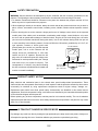
3LCD DATA PROJECTOR
TLP-X10U/11U/20U/21U
TLP-X10E/11E/20E/21E
TLP-X10Y/11Y/20Y/21Y
TLP-X20C/21C
TXP-X20/21
FAN
Y
BUS
P
ON
P LAM
TEM
DBY
TAN
ON/S
T
INPU
U
MEN
EXIT
ER
ENT
/ADJ
.
VOL
KEYAUT
STOO
NE
UTER
IN 2
MP
CO
UTER)
MP
CO B/PR
( Y/P
IN 1
T
OR
NIT
OU
MO
B
US
L
NTRO
CO
O
DIO
DIO
AU T
OU
DIO
AU
IN
R - AU
O INEO
VIDE VID
-L
IDE
S-V
AUT
SET O
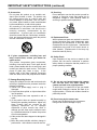
SAFETY PRECAUTION
WARNING: Service should not be attempted by anyone unfamiliar with the necessary precautions on this
projector. The following are the necessary precautions to be observed before servicing this chassis.
1. An isolation Transformer should be connected in the power line between the projector and the AC Iine
before any service is performed on the projector.
2. When replacing a chassis in the cabinet, always be certain that all the protective devices are put back in
place, such as; non-metallic control knobs, insulating covers, shields, isolation resistor-capacitor network
etc.
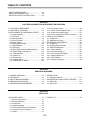
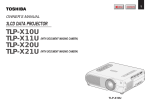
3. Before returning the set to the customer, always perform an AC Ieakage current check on the exposed
metallic parts of the cabinet, such as terminals, screwheads, metal overlays, control shafts etc. to be sure
the set is safe to operate without danger of electrical shock. Plug the AC Iine cord directly into a AC outlet
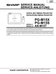
(do not use a line isolation transformer during this check). Use an AC voltmeter having 5000 ohm per volt
or more sensitivity in the following manner: Connect a1500 ohm 10W resistor, paralleled by a 0.15 uF, AC
type capacitor, between a known good earth
AC VOLTMETER
ground (water pipe, conduit, etc.) and the exposed
metallic parts, one at a time. Measure the AC
voltage across the combina-tion of 1500 ohm
resistor and 0.15 uF capacitor. Reverse the AC
plug at the AC outlet and repeat AC voltage mea0.15 uF
surements for each exposed metallic part. Voltage
mea-sured must not exceed 5.25V(rms). This
Place this probe on
each exposed
corresponds to 3.5 mA(AC). Any value exceeding
Good earth ground
metallic part.
such as a water
this limit consti-tutes a potential shock hazard and
pipe, conduit, etc.
1500 ohm
10W
must be corrected immediately.
PRODUCT SAFETY NOTICE
Many electrical and mechanical parts in this chassis have special safety-related characteristics. These
charac-teristics are often passed unnoticed by a visual inspection and the protection afforded by them cannot
neces-sarily be obtained by using replacement components rated for higher voltage, wattage, etc.
Replacement parts which have these special safety characteristics are identified in this manual and its
supplements; electrical components having such features are identified by the international hazard symbols
on the schematic diagram and the parts list.
Before replacing any of these components, read the parts list in this manual carefully. The use of substitute
replacement parts which do not have the same safety characteristics as specified in the parts list may create
shock, fire or other hazards.
ULTRAVIOLET DANGER IN SERVICE MODE
Eye damage may result from directly viewing the light produced by the lamp used in this product. Always turn
off lamp before opening this cover. Ultraviolet radiation eye protection required during servicing.
0-2
TABLE OF CONTENTS
SAFETY PRECAUTIONS .................................... 0-4
IMPORTANT PRECAUTIONS ............................. 0-4
IMPORTANT SAFETY INSTRUCTION ................ 0-5
SECTION 1
PART REPLACEMENT AND ADJUSTMENT PROCEDURES
1. LOCATION OF MAIN PARTS .............................. 1-1
2. LOCATION OF PC BOARD ................................. 1-1
3. REPLACEMENT OF MECHANICAL PARTS .......1-2
3-1. Lamp Assembly ............................................. 1-2
3-2. Top Cover.......................................................1-3
3-3. Main PC Board .............................................. 1-6
3-4. Drive PC Board ............................................. 1-7
3-5. Power Supply ................................................ 1-8
3-6. Ballast power Supply ................................... 1-10
3-7. Optical Engine ............................................. 1-12
3-8. LCD Panel ................................................... 1-14
3-9. MULTI-PBS (Polarizing Beam Splitter) ........1-18
3-10. Optical Engine Cooling Fan .......................1-19
3-11. Polarized Plate .......................................... 1-20
3-12. Intake Fan ................................................. 1-21
3-13. Exhaust Fan .............................................. 1-22
3-14. Speaker Block ........................................... 1-23
3-15. Video/Audio PC Board .............................. 1-24
3-16. Document camera ..................................... 1-25
3-17. Screws For Mechanical Parts ....................1-26
3-18. Screws For Optical Engine ........................ 1-27
3-19. How to disconnect FFC/FPC Connector ... 1-28
4. OPTICAL ADJUSTMENT ...................................1-32
4-1. Preparation .................................................. 1-32
4-2. Adjustment of Focus ....................................1-34
5. ELECTRICAL ADJUSTMENT ............................ 1-36
5-1. Preparation .................................................. 1-36
5-2. All adjust data download ............................. 1-37
5-3. Electrical adjustment ................................... 1-37
5-3-1. Menu selection ......................................... 1-38
5-3-2. Keystone setting (1) ................................. 1-39
5-3-3. Drive setting (DVI signal) ......................... 1-39
5-3-4. Setting signal level ................................... 1-41
5-3-5. White balance .......................................... 1-43
5-3-6. Keystone setting (2) ................................. 1-44
SECTION 2
SERVICING DIAGRAMS
1. TROUBLE SHOOTING .......................................
2. LED DISPLAY .....................................................
3. CIRCUIT BLOCK DIAGRAM ...............................
4. WIRING BLOCK DIAGRAM ...............................
5. CONNECTOR PIN ASSIGNMENT .....................
2-1
2-2
2-3
2-4
2-5
6. SERVICE JIGS
6-1. Extension cable kit .......................................
7. EXPLANATION OF MAIN / DRIVE PC BOARD .....
7-1. Main PCB .....................................................
7-2. Drive PCB ...................................................
2-7
2-8
2-8
2-9
SECTION 3
PARTS LIST
1. EXPLODED VIEWS ............................................
1-1. Remote Control Unit .....................................
1-2. Packing Assembly ........................................
1-3. Accessories ..................................................
1-4. Chassis Assembly ........................................
1-5. PC Board and Power Unit Assembly ............
1-6. Document Camera Assembly .......................
1-7. Labels ...........................................................
3-1
3-1
3-2
3-3
3-4
3-5
3-6
3-7
2. PARTS LIST ........................................................ 3-8
0-3
SAFETY PRECAUTIONS
WARNING:
TO REDUCE THE RISK OF FIRE OR ELECTRIC SHOCK, DO NOT EXPOSE THIS
APPLIANCE TO RAIN OR MOISTURE. DANGEROUS HIGH VOLTAGES ARE
PRESENT INSIDETHE ENCLOSURE. DO NOT OPEN THE CABINET. REFER
SERVICING TO QUALIRED PERSONNEL ONLY.
CAUTION:
Laser beam is emitted when the laser button of the remote control is pressed. Do not
look from the front of the remote control. Do not face toward a person or to a mirror.
RISK OF ELECTRIC SHOCK
DO NOT OPEN
CAUTION: TO REDUCE THE RISK OF
ELECTRIC SHOCK.
DO NOT REMOVE
COVER (OR BACK). NO USER SERVICEABLE
PARTS INSIDE.
REFER SERVICING TO
QUALIFIED SERVICE PERSONNEL.
FCC Radio Frequency Interference Statement
The lightning flash with arrowhead
symbol, within an equilateral triangle,
is intended to alert the user to the
presence of uninsulated "dangerous
voltage" within the product's
enclosure that may be of sufficient
magnitude to constitute a risk of
electric shock to persons.
Note:
This equipment has been tested and found to comply with the limits for a Class A
digital device, pursuant to part 15 of the FCC Rules. These limits are designed to
provide reasonable protection against harmful interference when the equipment is
operated in a commercial environment. This equipment generates, uses, and can
radiates radio frequency energy and, if not installed and used in accordance with the
instruction manual, may cause harmful interference to radio communications.
Operation of this equipment in a residential area is likely to cause harmful interference
in which case the user will be required to correct the interference at his own expense.
The exclamation point within an
equilateral triangle is intended to
alert the user to the presence of
important operating and
maintenance (servicing) instructions
in the literature accompanying the
appliance.
WARNING:
Changes or modifications made to this equipment, not expressly approved by
Toshiba, or parties authorized by Toshiba, could void the user's authority to operate
the equipment.
Notice:
This Class A digital apparatus complies with Canadian ICES-003.
Cet appareil numerique de la classe A est conforme a la norme NMB-003 du Canada.
IMPORTANT PRECAUTIONS
Save Original Packing Materials
The original shipping carton and packing materials will come in handy
if you ever have to ship your LCD projector. For maximum protection,
repack the set as it was originally packed at the factory.
Avoid Volatile Liquid
Do not use volatile liquids, such as an insect spray, near the unit.
Do not leave rubber or plastic products touching the unit for a long
time. They will mar the finish.
In the spaces provided below, record the Model and Serial No. Iocated
at the bottom of your LCD projector.
Mode No.
Serial No.
Retain this information for future reference.
Moisture Condensation
Never operate this unit immediately after moving it from a cold
location to a warm location. When the unit is exposed to such a
change in temperature, moisture may condense on the crucial
internal parts. To prevent the unit from possible damage, do not use
the unit for at least 2 hours when there is an extreme or sudden
change in temperature.
0-4
IMPORTANT SAFETY INSTRUCTIONS
CAUTION: PLEASE READ AND OBSERVE ALL WARNINGS AND INSTRUCTIONS GIVEN IN OWNER'S
MANUAL AND THOSE MARKED ON THE UNIT. RETAIN THIS BOOKLET FOR FUTURE REFERENCE.
This set has been designed and manufactured to assure personal safety. Improper use can result in electric
shock or fire hazard. The safeguards incorporated in this unit will protect you if you observe the following
procedures for installation, use and servicing. This unit is fully transistorized and does not contain any parts
that can be repaired by the user.
DO NOT REMOVE THE CABINET COVER, OR YOU MAY BE EXPOSED TO DANGEROUS VOLTAGE.
REFER SERVICING TO QUALIFIED SERVICE PERSONNEL ONLY.
1. Read Owner's Manual
After unpacking this product, read the owner fs
manual carefully, and follow all the operating and
other instructions.
4. Ventilation
Openings in the cabinet are provided for
ventilation and to ensure reliable operation of the
product and to protect it from overheating, and
these openings must not be blocked or covered.
The openings should never be blocked by placing
the product on a bed, sofa, rug or other similar
surface. This product should not be placed in a
built-in installation such as a bookcase or rack
unless proper ventilation is provided or the
manufacturer fs instructions have been adhered
to.
2. Power Sources
This product should be operated only from the
type of power source indicated on the marking
label. If you are not sure of the type of power
supply to your home, consult your product dealer
or local power company. For products intended to
operate from battery power, or other sources,
refer to the operating instructions.
5. Heat
The product should be situated away from heat
sources such as radiators, heat registers, stoves,
or other products (including amplifiers) that
produce heat.
3. Source of Light
Do not look into the lens while the lamp is on. The
strong light from the lamp may cause damage to
your eyes or sight.
6. Water and Moisture
Do not use this product near water – for example,
near a bath tub, wash bowl, kitchen sink, or
laundry tub; in a wet basement; or near a
swimming pool and the like.
0-5
IMPORTANT SAFETY INSTRUCTIONS (continued)
7. Cleaning
Unplug this product from the wall outlet before
cleaning. Do not use liquid cleaners or aerosol
cleaners. Use a damp cloth for cleaning.
11. Object and Liquid Entry
Never push objects of any kind into this product
through openings as they may touch dangerous
voltage points or short-out parts that could result
in a fire or electric shock. Never spill liquid of any
kind on the product.
8. Power-Cord Protection
Power-supply cords should be routed so that they
are not likely to be walked on or pinched by items
placed upon or against them, paying particular
attention to cords at plugs, convenience
receptacles, and the point where they exit from
the product.
12. Do not place the product vertically
Do not use the product in the upright position to
project the pictures at the ceiling, or any other
vertical positions. It may fall down and dangerous.
9. Overloading
Do not overload wall outlets; extension cords, or
integral convenience receptacles as this can
result in a risk of fire or electric shock.
13. Stack Inhibited
Do not stack other equipment on this product or
do not place this product on the other equipment.
Top and bottom plates of this product develops
heat and may give some undesirable damage to
other unit.
10. Lightning
For added protection for this product during storm,
or when it is left unattended and unused for long
periods of time, unplug it from the wall outlet.
This will prevent damage to the product due to
lightning and power-line surges.
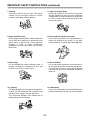
14. Attachments
Do not use attachments not recommended by the
product manufacturer as they may cause hazards.
0-6
IMPORTANT SAFETY INSTRUCTIONS (continued)
18. Servicing
Do not attempt to service this product yourself as
opening or removing covers may expose you to
dangerous voltage or other hazards. Refer all
servicing to qualified service personnel.
15. Accessories
Do not place this product on an unstable cart,
stand, tripod, bracket, or table. The product may
fall, causing serious injury to a child or adult, and
serious damage to the product. Use only with a
cart, stand, tripod, bracket, or table recommended
by the manufacturer, or sold with the product.
Any mounting of the product should follow the
manufacturer fs instructions, and should use a
mounting accessory recommended by the
manufacturer. A product and cart combination
should be moved with care. Quick stops, excessive
force, and uneven surfaces may cause the product
and cart combination to overturn.
19. Replacement Parts
When replacement parts are required, be sure the
service technician has used replacement parts
specified by the manufacturer or have the same
characteristics as the original part. Unauthorized
substitutions may result in fire, electric shock, or
other hazards. (Replacement of the lamp only
should be made by users.)
S3125A
16. If glass components, including lens and
lamp, should break, contact your dealer for
repair service.
This product incorporates glass components,
including a lens and a lamp. If such parts should
break, please handle with care to avoid injury and
contact your dealer for repair service. The broken
pieces of glass may cause to injury. In the
unlikely event of the lamp rupturing, thoroughly
clean the area around the projector and discard
20. Safety Check
Upon completion of any service or repairs to this
product, ask the service technician to perform
safety checks to determine that the product is in
proper operating condition.
17. Damage Requiring Service
Unplug this product from the wall outlet and refer
servicing to qualified service personnel under the
following conditions:
a) When the power-supply cord or plug is
damaged.
b) If liquid has been spilled, or objects have fallen
into the product.
c) If the product has been exposed to rain or
water.
d) If the product does not operate normally by
following the operating instructions. Adjust only
those controls that are covered by the
operating instructions as an improper
adjustment of other controls may result in
damage and will often require extensive work
by a qualified technician to restore the product
to its normal operation.
e) If the product has been dropped or damaged in
any way.
f) When the product exhibits a distinct change in
performance – this indicates a need for service.
21. Do not get your hands between the camera
arm and the main unit when setting the
camera arm back in its original position.
To avoid injury, be careful not to get your hands
caught when setting the camera arm back in its
original position. Families with children should be
particularly careful.
22. Do not carry by the camera arm.
Do not carry the projector by the camera arm.
Doing so can result in damage or injury.
0-7
IMPORTANT SAFETY INSTRUCTIONS (continued)
23. Do not leave documents on the unit for long
periods of time while using the document
imaging function.
Do not leave texts, papers or other documents for
projection on the unit for long periods of time. The
heat could erase the letters on a thermal paper.
24. Do not move the projector while the arm is
still erect.
Always store the arm back in position when moving
the projector. Otherwise injury or damage may
result.
25. Do not look into the arm light while it is lit.
The strong light may cause damage to your eyes
or sight.
0-8
SECTION 1
PART REPLACEMENT AND
ADJUSTMENT PROCEDURES
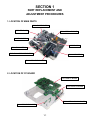
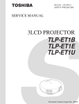
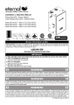
1. LOCATION OF MAIN PARTS
P800: POWER SUPPLY
SPEAKER BLOCK
E201: OPTICAL ENGINE
LAMP HOUSING
LCD BLOCK
Z101: EXHAUST FAN
P850: BALLAST POWER SUPPLY
Z100: INTAKE FAN
E201A: PROJECTION LENS
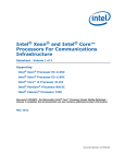
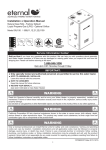
2. LOCATION OF PC BOARD
E101: MAIN PC BOARD
E102: DRIVE PC BOARD
E103: VIDEO/AUDIO PC BOARD
E104: SENSOR PC BOARD
1-1
CAUTIONS BEFORE SERVICING
Electronic parts are susceptible to static electricity and may easily be damaged, so do not forget to take
proper grounding treatment as required.
Many screws are used inside the unit. To prevent missing, dropping, etc. of the screws, always use a
magnetized screwdriver in servicing. Several kinds of screws are used and some of them need special
cautions. That is, take care of the tapping screws securing molded parts and fine pitch screws used to
secure metal parts. If they are used improperly, the screw holes will be easily damaged and the parts can
not be fixed.
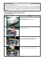
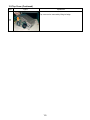
3. REPLACEMENT OF MECHANICAL PARTS
3-1. Lamp Assembly
Step
Figure
Explanation
Loosen 2 screws (M3 x 8).
These screws are retained with split washers.
1
Remove the lamp cover.
2
Loosen 2 screws that secure the lamp module (M3 x 8).
These screws are retained with split washers.
3
Lift the lamp module and slide out from the projector.
4
1-2
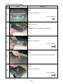
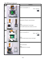
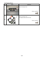
3-2. Top Cover
Step
Figure
Explanation
[Left Side]
1
Remove 3 screws (M3 x 6).
Screw : type [M-1]
[Right Side]
2
Remove 5 screws (M3 x 6).
Screw : type [M-1]
[Front]
3
Remove 3 screws (2 x 5).
Screw : type [M-2]
Remove front cover.
4
[Note]
Unsnap the bottom first, and then unsnap the top.
[Front]
5
Remove 1 screw (M3 x 6).
Screw : type [M-1]
1-3
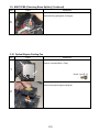
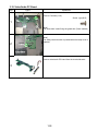
3-2. Top Cover (Continued)
Step
Figure
Explanation
[Rear]
6
Remove 3 screws (M2 x 5).
Screw : type [M-2]
Remove rear cover.
7
[Note]
Unsnap the bottom first, and then unsnap the top.
[Rear]
8
Remove 1 screw (M3 x 6).
Screw : type [M-1]
[Top]
Remove the small piece (One side is lifted and removed).
9
[Top]
10
Remove 1 screw (M3 x 6).
Screw : type [M-1]
1-4
3-2. Top Cover (Continued)
Step
Figure
Explanation
Top cover can be removed by lifting left edge.
11
1-5
3-3. Main PC Board
Step
Figure
Explanation
Remove all cables and connectors.
1
Remove 6 screws (M3 x 6).
2
Screw : type [M-1]
Remove 1 screws (M3 x 6).
Screw : type [M-1]
3
[Note]
The screw here is also fixing the grand wire.
1-6
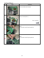
3-4. Drive PC Board
Step
Figure
Explanation
Remove all cables and connectors.
1
2b
2
Remove 5 screws (M3 x 6).
2a
Screw : type [M-1]
[Note]
The screw here is also fixing the grand wire.
2a
[Note]
The screw here is also fixing the grand wire.
2b
1-7
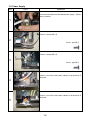
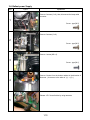
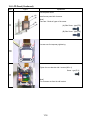
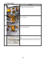
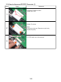
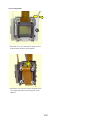
3-5. Power Supply
Step
Figure
Explanation
Disconnect the cable from the ballast power supply. (Plastic
case is opened)
1
Remove 1 screw (M3 x 8).
2
Screw : type [M-1]
Remove 1 screw (M3 x 8).
3
Screw : type [M-1]
Remove 1 hook from the bottom cabinet in the direction of
this arrow.
4
Remove 1 hook from the bottom cabinet in the direction of
this arrow.
5
1-8
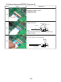
3-5. Power Supply (Continued)
Step
Figure
Explanation
Remove 1 screw (M3 x 6SW).
6
Screw : type [E-2]
1-9
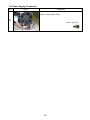
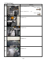
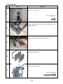
3-6. Ballast power Supply
Step
Figure
Explanation
Remove 2 screws (3 x 8), then, disconnect the lamp cable
connector.
1
Screw : type [M-3]
Remove 2 screws (3 x 8).
2
Screw : type [M-3]
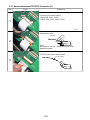
Remove 1 screw (M3 x 6).
3
Screw : type [M-1]
Remove 2 hooks from the bottom cabinet in the direction of
this arrow. ( It removes in the order of (1) → (2). )
4
(1)
(2)
Release 4 P.C. board holder by using tweezers.
5
1-10
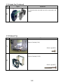
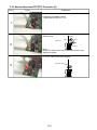
3-6. Ballast power Supply (Continued)
Step
Figure
Explanation
Remove the ballast power from the aluminum plate and
plastic case.
6
1-11
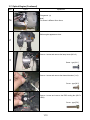
3-7. Optical Engine
Step
Figure
Explanation
Remove 4 screws (3 x 12). .......(a)-(d)
(c)
(d)
Screw : type [M-4]
1
(a)
(b)
Remove 1 screw (3 x 8). ........(e)
Screw : type [M-3]
(e)
Enlargement (a)
1a
Enlargement (b)
1b
Enlargement (c)
1c
Enlargement (d)
1d
1-12
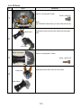
3-7. Optical Engine (Continued)
Step
Figure
Explanation
Enlargement (e)
1e
[Note]
This screw is different from others.
Whole engine appearance view.
2
Remove 1 screw and remove the lamp house (M3 x 6).
3
Screw : type [M-1]
Remove 1 screw and remove the thermal breaker (3 x 8).
4
Screw : type [M-3]
Remove 1 screw and remove the PBS cooling fan (M2.5 x
14SW).
5
Screw : type [E-9]
1-13
3-8. LCD Panel
Step
Figure
Explanation
(A)
Remove 3 screws (M3 x 8SW) .
Screw : type [E-1]
1
[Note]
Tear off adhesive tape when you remove the screw of (A).
Main frame
Separate the main frame and sub frame from the engine
block.
2
Sub frame
Bottom of main frame
Remove 3 screws (M3 x 12SW).
3
Screw : type [E-10]
Prism block
Separate the prism block from the main frame.
4
Main frame
1-14
3-8. LCD Panel (Continued)
Step
Figure
Explanation
Remove 4 screws (M2.6 x 6).
Screw : type [E-3]
5
Separate the LCD panel, mask and bracket.
6
Note]
Keep the mask because it is used again.
The old LCD Panel and four screws are not used.
Remove 4 screws (M2 x 4).
Screw : type [E-4]
7
[Note]
Keep the screws because they are used again.
Remove the bracket.
8
[Note]
This bracket will not use again.
1-15
3-8. LCD Panel (Continued)
Step
Figure
Explanation
Use the panel holder
(A)
(A)
(B)
9
Install a new panel with 4 screws.
[Note]
There are 2 kinds of types of the screw.
(A) Side Screw : type [E-5]
(B) Side Screw : type [E-6]
(B)
4 screws use for temporary tightening.
10
Tighten the new bracket with 4 screws (M2 x 4).
Screw : type [E-4]
11
[Note]
This 4 screws are from the old bracket.
1-16
3-8. LCD Panel (Continued)
Step
Figure
Explanation
Install the LCD panel holder assembly made by step 9 to the
prism block.
12
Fix the LCD panel holder assembly on the bracket with 2
screws (M2x2).
13
Screw : type [ E-7]
Fix a prism block on the lens block.
14
[Note] Panel holder service kit (23405001)
E-7
E-5
1-17
E-6
3-9. MULTI-PBS (Polarizing Beam Splitter)
Step
Figure
Explanation
Remove 4 screws (M2.5 x 8SW) .
1
Screw : type [E-8]
Remove the fitting spring from the the gap.
2
Remove the Multi-PBS.
3
Lamp
[Note]
Make sure the direction of the PBS when you install.
4
Prism
Insert the new Multi-PBS.
5
1-18
3-9. MULTI-PBS (Polarizing Beam Splitter) (Continued)
Step
Figure
Explanation
Install the fitting spring back to the gap.
6
3-10. Optical Engine Cooling Fan
Step
Figure
Explanation
Remove 3 screws (M2.5 x 5SW) .
1
Screw : type [E-11]
Remove the optical engine cooling fan.
2
1-19
3-11. Polarized Plate
Step
Figure
Explanation
Lift the stopper up by using the tweezers.
1
Remove the stopper.
2
Remove the polarized plate.
3
Panel Side
polarizer film
4
[Note]
The film side must be faced to the LCD panel when installing
and the color must be related with the color of LCD panel.
Color
Marking
1-20
3-12. Intake Fan
Step
Figure
Explanation
Remove 1 screw (3 x 8).
1
Screw : type [M-3]
Remove intake fan block from the bottom cabinet.( It pulls
up along with a rail. )
Rail
2
Fan block
Remove filter block from the intake fan block.
3
The filter is split like this.
4
Remove 3 screws (3 x 35).
5
Screw : type [M-6]
1-21
3-12. Intake Fan (Continued)
Step
Figure
Explanation
The intake fan block is divided into the fan, senser pcb, and
bracket.
6
3-13. Exhaust Fan
Step
Figure
Explanation
Remove 2 screws (3 x 8).
1
Screw : type [M-3]
Remove 2 screws (3 x 30).
2
Screw : type [M-5]
1-22
3-14. Speaker Block
Step
Figure
Explanation
Remove 2 screws (3 x 8).
1
Screw : type [M-3]
Remove 2 screws (3 x 8).
The speaker will be removed like this.
2
Screw : type [M-3]
1-23
3-15. Video/Audio PC Board
Step
Figure
Explanation
Remove 5 screws (3 x 8).
Screw : type [M-3]
1
[Note]
The screw here is also fixing the grand wire.(Green marked)
2
Switch
[Note]
The safety interlock switch is pushed when the lamp cover is
replaced.
Lamp Cover
Remove video/audio PC board from the terminal bracket.
3
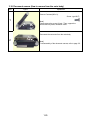
1-24
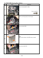
3-16. Document camera (How to remove from the main body)
Step
Figure
Explanation
Remove 5 screws (M3 x 8).
Screw : type [M-7]
1
(A)
[Note]
Please remove the screw (A) last. Then, support the
camera block by hand, otherwise it falls.
Disconnect the connector from the main body.
2
[Note]
For disassembly of the document camera, refer to page 3-6.
1-25
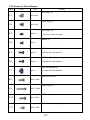
3-17. Screws for Mechanical Patrs
Type
M-1
Form
Size
M3 x 6
Location
Top Cover (11), Main PCB (7), Drive PCB (5),
Ballast Power Supply (1), Video/audio PCB (5) and
Lamp House (1)
Front Cover (3) and Rear Cover (3)
M-2
M-3
2x4
3x8
Power Supply (1), Ballast Power Supply (2),
Ballast cable connector (1), Intake FAN (1),
Optical Engine (1), Exhaust FAN (2) and Speaker Block
(4)
Optical Engine (4)
M-4
3 x 12
Exhaust FAN (2)
M-5
3 x 30
Intake FAN (3)
M-6
3 x 35
Document camera (5)
M-7
M3 x 8
1-26
3-18. Screws for Optical Engine
Type
Form
Size
Location
LCD PANEL (3)
E-1
M3 x 8SW
Power Supply (1)
E-2
M3 x 6SW
LCD PANEL (4)
E-3
M2.5 x 6
* This screw will not use again.
Bracket (4)
E-4
M2 x 4
LCD Panel (connector side) (2)
E-5
M2.5 x 6
*Contained in Panel holder kit.
LCD Panel (2)
E-6
M2.5 x 6
*Contained in Panel holder kit.
LCD Panel Bracket (2)
E-7
M2 x 2
*Contained in Panel holder kit.
Multi-PBS Cover (4)
E-8
M2.5 x 8SW
Optical Engine (1)
E-9
M2.5 x 14SW
LCD Panel (3)
E-10
M3 x 12SW
Optical Engine Cooling FAN (3)
E-11
M2.5 x 5SW
1-27
3-19. How to disconnect FFC/FPC Connector (1)
Step
Figure
Explanation
Conformity of Location number.
MAIN PCB: PJ701
1
Hook
Release Two hooks.
[Note]
Hooks stop on the way. Please do not pull out by
superfluous power.)
2
Electrodes (up side)
FFC/FPC cable can be disconnected.
3
1-28
3-19. How to disconnect FFC/FPC Connector (2)
Step
Figure
Explanation
Conformity of Location number.
MAIN PCB: PJ801
DRIVE PCB: PJ751
1
Hook cover
Release hook cover.
Release
Hook cover
Side view
2
Lock
Cable
Connector
[Note]
Hook cover stops on the way. Please do not pull out by
superfluous power.
FFC/FPC cable can be disconnected.
3
Printed electrodes
1-29
3-19. How to disconnect FFC/FPC Connector (3)
Step
Figure
Explanation
Hook
1
Conformity of Location number.
MAIN PCB: PJ301, PJ802
DRIVE PCB: PJ851, PJ901, PJ951
Hook
Connector
Release tow hooks.
Side view
Release
Hook
Cable
2
Lock
[Note]
Hook stops on the way. Please do not pull out by
superfluous power.
FFC/FPC cable can be disconnected.
Printed electrodes
3
1-30
3-19. How to disconnect FFC/FPC Connector (4)
Step
Figure
Explanation
Conformity of Location number.
VIDEO/AUDIO PCB: PJ1, PJ5
1
Hook
Release hook.
Release
Side view
Cable
Hook
Lock
2
Connector
[Note]
Hook cover stops on the way. Please do not pull out by
superfluous power.
FFC/FPC cable can be disconnected.
Printed electrodes
3
1-31
4. OPTICAL ADJUSTMENT
4-1. Preparation
< Test Equipments and Test Jigs >
Personal computer (Windows P/C, OS:windows 95/98)
Adjustment software SINGO98.exe
RGB cable
A precise screwdriver (minus)
Hexagon Wrench (include Panel holder service kit) (Refer to page 1-17)
Extension cable kit (Refer to page 2-7)
..
..
..
(1) Setting
Put PJ on the horizontal place, and project it on the
vertical screen.
(6) Test Pattern Setup
Connect a computer with RGB cable, and start the
Pattern generating software (SINGO98.exe).
.
(2) Remove top cover
Refer to page 1-3.
(3) Remove Main PC board
Refer to page 1-6.
(4) Connect LCD panels by using extension cables
Connect PJ851 and R-Panel with extension cable.
Connect PJ901 and G-Panel with extension cable.
Connect PJ951 and B-Panel with extension cable.
..
.
..Click cross hatch button.
Click [R] and [B] button to display G-Cross Hatch.
(5) Connect Main PC board by using extension cable kit
Be careful not to touch circuit and cabinet.
1-32
(7) Focus Adjustment
A
.When this screw (A) is loosened, the panel moves to
front and back, and focus can be adjusted.
B
B
B
B
.When these screws (B) are loosened, the panel moves
to left,right,up and down, and convergence can be
adjusted.
1-33
4-2. Adjustment of Focus (ex. Red panel exchange)
Step
Figure
Explanation
TEST PATTERN : Green Cross Hatch
1
Adjust focus by projection Lens.
TEST PATTERN : Red Cross Hatch
Move the panel in front and back, and adjust the focus.
Tighten two screws little by little.
2
3
Tighten two screws, when you reached to the best focus
point.
4
1-34
4-2. Adjustment of Focus (ex. Red panel exchange) (Continued)
Step
Figure
Explanation
TEST PATTERN : Red and Green Cross Hatch
5
Move the panel in left, right, up and down, and adjust the
convergence.
6
Tighten four screws.
7
1-35
5. ELECTRICAL ADJUSTMENT
5-1. Preparation
< Test Equipments and Jigs >
Personal computer (Windows P/C, OS:windows 95/98)
Adjustment software
SINGO98.exe, TLPX10S.exe, CNTX10S.exe
RGB cable, Serial control cable (for RS-232C)
Oscilloscope
Digital voltmeter
Extension cable kit (Refer to page 2-7)
..
..
..
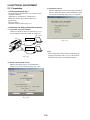
(3) Adjustment software
Electrical adjustment is carried out using the adjustment
software. When the software (TLPX10S.EXE)is started,
a screen like the following image (Fig. 1-4-3) appears.
< Connection and Setting of Personal Computer >
(1) Connection of personal computer
Connect a computer as shown in following Fig. 1-4-1.
Use the supplied serial control cable for connection.
TEST PATERN
Install singo98.exe
Fig. 1-4-3
UTER
IN 2
MP
CO
UTER)
MP
CO B/PR
( Y/P
IN 1
RGB cable
T
OR
NIT
OU
MO
B
US
L
NTRO
CONTROL
CO
O
DIO
DIO
AU T
OU
DIO
AU
IN
IN
EO EO
VID VID
-L
IDE
S-V
R - AU
Install TLPX10S.exe
and CTLX10S.exe
Serial control cable
Fig. 1-4-1
(Note)
Electrical adjustment menu changes automatically by
pressing [next] button with every step. This software
transmits the necessary command automatically.
(2) Data download/upload software
When the download software (CTLX10S.EXE) is
started, screen like the following image (Fig. 1-4-2)
Fig. 1-4-2
1-36
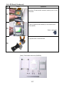
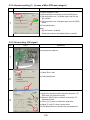
5-2. All adjust data download (When the Main PC board will be replaced.)
Step
Figure
Explanation
Start the download software (CNTX10S.exe).
Press [UP/DW] tab.
1
Press [Read] button.
The all data will be read form projector in a few minutes.
2
When a dialog is indicated, it finishes reading all data.
Key in the file name (=Serial Number).
3
Press [Save] button to save the data.
After replacing the Main PC Board, press [Write] button.
4
1-37
Step
Figure
Explanation
When this dialog is indicated, select the data file (=Serial
Number).
Press [Open] button.
5
When this message screen appears, press [ok] button.
Then, all data (in the old PCB) will be written to the
projector.
6
Check the all input signals.
All input signals is fare, press [Save] Button.
7
5-3. Electrical adjustment
5-3-1. Menu selection
Step
Figure
Explanation
Start the download software (TLPX10S.exe).
Select the parts that you changed.
1
Press [OK] button.
1-38
5-3-2. Keystone setting (1) (In case of Main PCB was changed.)
Step
Figure
Explanation
(1) Select "Keystone1" step.
(2) Set the projector horizontally, and click [KC0] button.
(3) Set the projector to a +30 degree angle, and click the
[KC1] button.
(4) Set the projector to a -30 degree angle, and click [KC2]
button.
(5) Press [Next] button.
1
[Note]
* A green button is available.
* All the data is saved, when [Next] button is pushed.
5-3-3. Drive setting (DVI signal)
Step
Figure
Explanation
Use the extension cable kit.
1
(1) Select "Drive" step.
(2) Press [Start] button.
2
3
(1) Monitor the waveform at the respective test point ("TPRIN" when you adjust the R level).
(2) When the [WN7] button is clicked, you enter the "R"
adjustment mode.
(3) Click [+] or [-] button to adjust the signal level.
(4) Adjust "G" and "B" colors to be the same.
(5) Click [Next] button to proceed to the next adjustment.
1-39
Step
Figure
Explanation
(1) Monitor the waveform at the test point "TP-R".
(2) Click [WM7] button and adjust to the specified level.
4
(3) Check the voltage at the test points "TP-R" and "TP-B".
(4) Click [Next] button.
[Note]
"G" and "B" levels also change when [WM7] adjustment
is performed.
(1) Monitor the waveform at test point "TP-R".
5
(2) Click [W03] button and adjust to the specified level.
( [W09] and [W0C] are the same process.)
(3) Click [Next] button.
(1) Monitor the waveform at test point "TP-G".
(2) Click [W04] button and adjust to the specified level.
( [W0A] and [W0D] are the same process.)
6
(3) Click [Next] button.
(1) Monitor the waveform at test point "TP-B".
(2) Click [W05] button and adjust to the specified level.
( [W0B] and [W0E] are the same process.)
7
(3) Click [Next] button.
1-40
5-3-4. Setting signal level
Step
Figure
Explanation
(1) Select "Signal level" step.
(2) Press [Start] button.
1
(1) Press [VSR] button and click [+] or [-] button to adjust the
signal level.
2
(2) Press [VGR] button and click [+] or [-] button to adjust
the signal level.
(3) Press [Next] button.
(1) Press [VSG] button and click [+] or [-] button to adjust the
signal level.
3
(2) Press [VGG] button and click [+] or [-] button to adjust the
signal level.
(3) Press [Next] button.
(1) Press [VSB] button and click [+] or [-] button to adjust the
signal level.
4
(2) Press [VGB] button and click [+] or [-] button to adjust the
signal level.
(3) Press [Next] button.
1-41
Step
Figure
Explanation
(1) Press [VSR] button and click [+] or [-] button to adjust the
signal level.
5
(2) Press [VGR] button and click [+] or [-] button to adjust the
signal level.
(3) Press [Next] button.
(1) Press [VSG] button and click [+] or [-] button to adjust the
signal level.
6
(2) Press [VGG] button and click [+] or [-] button to adjust the
signal level.
(3) Press [Next] button.
(1) Press [VSB] button and click [+] or [-] button to adjust the
signal level.
7
(2) Press [VGB] button and click [+] or [-] button to adjust the
signal level.
(3) Press [Next] button.
SOURCE : DVD Color bar component Y signal.
(1) Press [VSR] button and click [+] or [-] button to adjust the
signal level.
8
(2) Press [VGR] button and click [+] or [-] button to adjust the
signal level.
(3) Press [Next] button.
NOTE: Display image disappears when [VSR] button is
pushed.
1-42
Step
Figure
Explanation
(1) Press [VSG] button and click [+] or [-] button to adjust the
signal level.
(2) Press [VGG] button and click [+] or [-] button to adjust the
signal level.
9
(3) Press [Next] button.
NOTE: Display image disappears when [VSG] button is
pushed.
(1) Press [VSB] button and click [+] or [-] button to adjust the
signal level.
(2) Press [VGB] button and click [+] or [-] button to adjust the
signal level.
10
(3) Press [Next] button.
NOTE: Display image disappears when [VSB] button is
pushed.
(1) Select a red single color screen when adjusting R. Click
[WM6] button, and adjust the flicker level to minimum in
both + and - directions, taking note of the data values.
Then set data to the mid-point between the two
previously noted values.
(2) Adjust other colors to be the same, using [WM5] for
green and [WM4] for blue.
(3) Click [Upside Down] button to change projection mode.
(4) Adjust this mode in the same way.
(5) Click [Next] buttons.
11
5-3-5. White balance
Step
Figure
Explanation
(1) Select "White Balance" step.
(2) Press [Start] button.
1
1-43
Step
Figure
Explanation
(1) Click [W03] and/or [W05] buttons, and adjust screen until
it becomes a natural gray.
(2) Click [W09] and/or [W09] or [W0A] buttons, and adjust
screen until it becomes a natural gray.
2
(3) Click [Next] button.
(1) Click [WN7] and/or [WN9] buttons, and adjust screen
until it becomes a natural gray.
(2) Click [Next] button.
3
5-3-6. Keystone setting (2)
Step
Figure
Explanation
(1) Set the projector horizontally, and click [KC3] button.
[Note - Important]
1
The deviation of the inclination sensor due to rise in
temperature is corrected by measuring after warming
up for approximately one hour.
When the adjustment is completed, press [OK] button.
2
1-44
SECTION 2
SERVICING DIAGRAMS
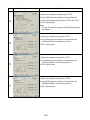
1. TROUBLE SHOOTING
CAUSE
CHECK POINT
Flat cable of Power supply
(disconnect PJ701)
CHEK ITEM
Standby voltage
(See page 2-4)
Power is not on
Power off during use
JUDGE
(NG)
→ Power supply is NG.
(OK)
→ Check next step.
PJ701(connect PJ701)
Standby voltage
(NG)
→ Main PCB is NG,
or any cable connection is NG.
LED Display
Lighting pattern
See 2-2
(Damaged)
→ Change with new lamp.
Lamp is not on
Lamp
"No Signal" OSD message
Any damage inside
or not
Indicated or not
(Not Damaged)
→ Check Lamp cover, PJ11 or
lamp power supply.
However, even if the lamp has
no damage, there is the case it
has trouble also.
(Indicated)
→ RGB/Video terminal is NG,
or Main PCB is NG.
(Not Indicated)
→ Check next step.
No image
Test Point
TP-R
TP-G
TP-B
Signal shape
(Correct)
→ LCD panel is NG,
or PJ851/PJ901/PJ951 is NG.
(Incorrect)
→ Main PCB is NG.
ATTENTION
LED displays various error pattern. (See 2-2)
Be careful because the same error occurs in the bad contact of the cable as well.
LED error combination display always show the latest error.
2-1
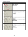
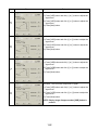
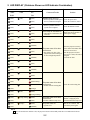
2. LED DISPLAY (Problems Shown on LED Indicator Combination)
Status of Indicator Light
TEMP
LAMP
BUSY
(OFF)
(OFF)
(OFF)
(RED)
(OFF)
(OFF)
(OFF)
(OFF)
(OFF)
(OFF)
(OFF)
(OFF)
(OFF)
(OFF)
(OFF)
Check the each cooling fan.
The power turns off or does
not come on
>Trouble with the Lamp cover
The lamp cover is not properly
attached. Unplug the power
cord and reattach the lamp cover.
The power turns off
> System error.
Wait for two minutes, and
turn on the power again.
(RED)
(RED)
(RED)
(RED)
(RED)
(Orange flashing)
(Orange flashing)
(OFF)
(OFF)
The power turns off or does
not come on
> Trouble with the cooling fans.
(RED)
(Orange)
(OFF)
(OFF)
(RED)
(RED Flashing)
(OFF)
(OFF)
Place the projector correctly
so the intake and exhaust fan's
holes are not covered.
Turn the projector off, and
leave it for a while, and turn it
on again.
Clean the air filter.
(RED)
(OFF)
(OFF)
(RED)
(GREEN)
(OFF)
(OFF)
The power turns off or does
not come on
> The inside is too hot, or the
projector has been working in
an area of high temperature.
(RED)
(OFF)
(OFF)
(OFF)
Change new lamp.
There may also be trouble in
ballast power supply.
(GREEN)
(OFF)
(GREEN)
The lamp went out during use
or the lamp will not switch on
> The bulb has reached the end
of it's life
(RED)
(OFF)
(OFF)
(GREEN)
Standby-power is not on
> There's a problem with the power Check the power unit.
Check the connector ( PJ12).
unit or system microcomputer.
Power is not on
> There's a problem with the
Check the main PC board.
system microcomputer.
(GREEN)
(OFF)
(Orange)
Solution
(OFF)
(OFF)
(Orange)
(RED)
(OFF)
(OFF)
(RED)
(RED)
(OFF)
(OFF)
(RED)
(OFF)
(OFF)
(OFF)
(OFF)
Cause and Trouble
FAN
(OFF)
(OFF)
ON
(RED)
(OFF)
(Orange)
(RED)
(GREEN)
NOTE
In each mode shown with this color, the projector returns to the standby mode after error indication for about
2 minutes.
2-2
DRIVE BOARD
14.318MHz
RGB OUT
MAIN CLK
ICS301M
MAX497
DVI connector
D-sub 15pin
DRIVE DATA
EEPROM
MCU for
DRIVE
Timing Signal
Level Shift
5V->15V
I2C
CTRL
DDC
ROM
CTRL
ET1030
LVDS DRV.
graphic port
ANALOG
SW
AD8170
MAX496
ANALOG-1
RGB/YPbPr
COMM (MAIN-DRIVE)
75.0MHz
TMDS I/F
SiI151A
DIGITAL RGB
ANALOG-2
RGB
PANEL CLK
SG8002JCPCC
128.862MHz
A/D
CONVERTER
AD9886
ANALOG
SW
LT1675
DDC
ROM
SCALER
DS90C385
3WIRE
PW364
COMM (MAIN-SCALER)
EEPROM
I2C
SYNC SEP
TA1318N
CTRL
Timing GEN
for LCD
ET2090
D/A
CONVERTER
MB40C950
Timing Signal
Level Shift
5V->15V
RAM
CLAMP PULSE
I2C
3WIRE
TLP-X11 only
INTERFACE
PLD
XC2S50
LVDS REC.
DS90C364
YUV 16bit 14.318MHz
CAMERA
FAN SPEED PULSE
(145Mpixel)
RED
Panel
ROM
ANGLE
SENSOR
I2C
LT1260
Sample & Hold
Invert
ET6050
I2C
video port
MATRIX
TA1276AF
LVDS REC.
DS90C386
PREAMP
CXA2067
ET1030
Shading
Correct
CXD3503R
Sample & Hold
Invert
ET6050
GREEN
Panel
I2C
RS232C I/F
uPD4721
I2C
3WIRE?
I2C
VIDEO
DECODER
VIDEO
2-3
S-Terminal
S-VIDEO
PROG.
SCAN
SAA7118
Pin jack
Y/C SEP.
MM1031
I2C
Pre-Driver
CXA2111R
RGB Signal
EEPROM
VIDEO/AUDIO BOARD
MCU
Sample & Hold
Invert
ET6050
VIDEO AMP
MM1510
24.576MHz
VIDEO AMP
MM1510
MM1041
I2C
JPEG
MD2208
POWER AMP
LA4425A
DRAM
D/A
M62393
Pin jack x2
analog
1H
16Mbitx2
Mini jack
VIDEO AUDIO
ET1030
Gamma
Amp
SH-3
SDA9400
CODEC
RGB AUDIO
Timing Signal
Level Shift
5V->15V
I2C
1H
1H
REMOTE CONTROL
SELECTOR
M52055FP
VOL. CTRL
M62420FP
I2C
CTRL
PCMCIA
CONTROLLER
Mini jack
MR-SHPC-01
AUDIO OUT
POWER SUPPLY:
12-13V(P-AMP)
14V
9V(SW,VOL,BUFF)
6V
CTRL
PC Card SLOT
POWER ON
FAN CONTROL
5V(VOL,V-AMP)
POWER
SUPPLY
POWER
CONTROLLER
PU2211
I2C
KEY SWITCH
TEMP SENSOR
1
I2C
TEMP SENSOR
2
I2C
TEMP SENSOR
OPTICAL BOX
I2C
TEMP SENSOR
INTAKE FAN
CTRL
LAMP ON
CTRL
LAMP FAIL
SDRAM
128Mbitx2
RS232C
INTERFACE
Mini DIN 8 pin
RS-232C
uPD4721
ROM
USB connector
LED
REMOTE
CONTROL
RECEIVER
(FRONT/REAR)
USB I/F
PDIUSBD12
I2C
USB
D/A
M62393
FAN
CONTROL(X3)
FAN SPEED PULSE
LAMP
BALLAST
BLUE
Panel
3. CIRCUIT BLOCK DIAGRAM
MAIN BOARD
D-sub 15pin
4. WIRING BLOCK DIAGRAM
PJ751
DRIVE PC BOARD
PJ901
PJ601
P102
CAMERA
PC BOARD
LCD
G
N.C.
P101
PJ851
LCD
R
LCD
B
PJ951
PJ360
LED PC BOARD
PJ1
PJ5
PJ2
VIDEO/AUDIO PC BOARD
PJ352
PJ353
RERAY
PC BOARD
PJ351
PJ350
PJ301
PJ304
PJ802
PJ801
MAIN PC BOARD
MAIN
POWER
UNIT
PJ701
PJ11
PJ12
PJ502
PJ503
PJ501
PJ29
PJ504
PJ201
THERMAL
SWITCH
LAMP
DRIVER
SENCOR PC BOARD
2-4
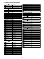
5. CONNECTOR PIN ASSIGNMENT
PJ11 (MAIN)
PJ504 (LAMP DRIVER)
1 LAMP POWER
+1.3V(on) / 0V(off)
2 GND
0V
3 LAMP ERROR
(error) / 0V(normal)
4 LAMP PWR CONT
(Low) / 0V(High)
5 +6.15V (SWITCHED)
+6.15V(error) / 0V(normal)
20
21
22
23
24
25
26
27
28
29
30
PJ12 (MAIN)
THERMAL SWITCH
1 +6.15V (SWITCHED)
0V
2 +6.15V
+6.15V
PJ29 (MAIN)
PJ201 (SENSOR)
1 GND
0V
2 GND
0V
3 SHS+5V
+5V
4 SHTMP +3.3V
+3.3V/0V
5 SHS+5V
+5V
6 SHV3V_SCL
+3.3V/0V
7 SHV3V_SDA
+3.3V/0V
8 GND
0V
9 GND
0V
PJ301 (MAIN)
1 GND
2 GND
3 +17V
4 +17V
5 +17V
6 GND
7 GND
8 +6.5V
9 +6.5V
10 +6.5V
11 GND
12 +4.5V
13 +4.5V
14 GND
15 GND
16 DRV_TX
17 DRV_RX
18 GND
19 TXOUT0+
20 TXOUT021 TXOUT1+
22 TXOUT123 TXOUT2+
24 TXOUT225 TXOUT3+
26 TXOUT327 TXCLKOUT+
28 TXCLKOUT29 GND
30 GND
PJ751(DRIVE)
0V
0V
+17V
+17V
+17V
0V
0V
+6.5V
+6.5V
+6.5V
0V
+4.5V
+4.5V
0V
0V
+/- 7V (data)
+/- 7V (data)
0V
+3.3V(Pulse)
+3.3V(Pulse)
+3.3V(Pulse)
+3.3V(Pulse)
+3.3V(Pulse)
+3.3V(Pulse)
+3.3V(Pulse)
+3.3V(Pulse)
+3.3V(Pulse)
+3.3V(Pulse)
0V
0V
PJ304 (MAIN)
1 RXIN02 RXIN0+
3 RXIN14 RXIN1+
5 RXIN26 RXIN2+
7 RXIN38 RXIN3+
9 GND
10 GND
11 -9V
12 +17V
13 GND
14 GND
15 CAMRX
16 +5V
17 CAM TX
18 CAM DET
19 CAM REM
PJ350 (RELAY), P102 (CAMERA UNIT)
+1.5V(Pulse)
+1.5V(Pulse)
+1.5V(Pulse)
+1.5V(Pulse)
+1.5V(Pulse)
+1.5V(Pulse)
+1.5V(Pulse)
+1.5V(Pulse)
0V
0V
-9V
+17V
0V
0V
+/- 7V (data)
+5V
+/- 7V (data)
0V
+5V
CAM LIGHT
MAIN POER
CAM KEY0
CAM LED
CAM KEY1
CAM RES
CAM KEY2
CAM ARM
CAM KEY3
CAM KEY5
CAM KEY4
+5V
+5V
+5V
+5V
+5V
+5V
+5V
+5V
+5V
+5V
+5V
PJ501 (MAIN)
INTAKE FAN
1 FAN4 CONTROL V
6 to +13V
2 GND
0V
3 FAN4 PULSE
+3.3V(Pulse)
PJ502 (MAIN)
PBS FAN (OPTICSL ENGINE)
1 FAN1 CONTROL V
6 to +13V
2 GND
0V
3 FAN1 PULSE
+3.3V(Pulse)
4 N.C.
0V
PJ503 (MAIN)
COOLING FAN (OPTICAL ENGINE)
1 FAN2 CONTROL V
6 to +13V
2 GND
0V
3 FAN2 PULSE
+3.3V(Pulse)
PJ504 (MAIN)
EXHAUST FAN
1 FAN3 CONTROL V
6 to +13V
2 GND
0V
3 FAN3 PULSE
+3.3V(Pulse)
4 N.C.
0V
PJ701 (MAIN)
POWER SUPPLY
1 +4.5V
+4.5V
2 +4.5V
+4.5V
3 +4.5V
+4.5V
4 GND
0V
5 GND
0V
6 GND
0V
7 +6.5V
+6.5V
8 +6.5V
+6.5V
9 +6.5V
+6.5V
10 GND
0V
11 AUDIO GND
0V
12 AUDIO GND
0V
13 +14V_2
+14V
14 +14V_2
+14V
15 GND
0V
16 GND
0V
17 FAN4 CONTROL V
+6.5V
18 GND
0V
19 +14V_1
+14V
20 GND
0V
21 +17V
+17V
22 GND
0V
23 -9V
-9V
24 GND
0V
25 LAMP POWER CNOT
0V
26 FAN4 CONT
+4.5V
27 FAN ON/OFF
+4.5V
28 GND
0V
2-5
PJ851,PJ901,PJ951 (DRIVE)
1 VSSY
2 NDIRY
3 DIRY
4 DY
5 NRG
6 N.C
7 LCCOM
8 VID12
9 VID10
10 VID8
11 VID6
12 VID4
13 VID2
14 VSSX
15 ENB1
16 ENB2
17 DIRX
18 NDIRX
19 VDDX
20 DX
21 CLX
22 NCLX
23 VSSX
24 VID1
25 VID3
26 VID5
27 VID7
28 VID9
29 VID11
30 LCCOM
31 NRS1
32 NRS2
33 VDDY
34 CLY
35 NCLY
36 DY
PJ801 (MAIN)
PJ5 (VIDEO/AUDIO)
1 +14V_1
+14V
2 +14V_1
+14V
3 GND
0V
4 GND
0V
5 +5.5V
+5.5V
6 +5.5V
+5.5V
7 +5.5V
+5.5V
8 GND
0V
9 GND
0V
10 GND
0V
11 +4.5V
+4.5V
12 +4.5V
+4.5V
13 GND
0V
14 GND
0V
15 +14V_1
+14V
16 +14V_1
+14V
17 +14V_1
+14V
18 +14V_1
+14V
19 AUDIO GND
0V
20 AUDIO GND
0V
21 AUDIO GND
0V
22 AUDIO GND
0V
23 MAIN POWER
+5.5V/0V
24 AUDIO POWER
+5.5V/0V
25 GND
0V
26 GND
0V
27 SHV3V_SCL
+3.3V/0V
28 SHV3V_SDA
+3.3V/0V
29 VIDSCL+5V
+5V/0V
30 VIDSDA+5V
+5V/0V
PJ802 (MAIN)
PJ1 (VIDEO/AUDIO)
1 VSEN
+5V
2 SSEN
0V
3 COVER
0V
4 GND
0V
5 GND
0V
6 SYNC SEP V
0/3.3V (component)
7 GND
0V
8 SYNC SEP H
0/3.3V (component)
9 GND
0V
10 Y SYNC
1Vp-p (component)
11 GND
0V
12 3D CROMA
1Vp-p (NTSC)
13 GND
0V
14 3D LUMINANCE
1Vp-p (NTSC)
15 GND
0V
16 C IN
1Vp-p
17 GND
0V
18 Y IN
1Vp-p
19 GND
0V
20 CVBSIN
1Vp-p
+6V
+2V to +12V
+2V to +12V
+2V to +12V
+2V to +12V
+2V to +12V
+2V to +12V
0V
0 to +15.5V (Pulse)
0 to +15.5V (Pulse)
0 /+15.5V
0 /+15.5V
15.5V
0 to +15.5V (Pulse)
0 to +15.5V (Pulse)
0 to +15.5V (Pulse)
0V
+2V to +12V
+2V to +12V
+2V to +12V
+2V to +12V
+2V to +12V
+2V to +12V
+6V
2 to +6V (Pulse)
2 to +6V (Pulse)
15.5V
0 to +15.5V(Pulse)
0 to +15.5V(Pulse)
0 to +15.5V (Pulse)
PJ351 (RELAY)
1 CAM ARM
2 GND
ARM SWITCH
5V
0V
PJ352 (RALAY)
1 +15V_1
2 GND
3 GND
PJ360 (LED)
+15V
0V
0V
PJ353 (RALAY)
1 +15V_2
2 GND
3 +4V
4 GND
5 -8V
6 CAM RX
7 CAM TX
8 GND
9 CAM RESET
10 N.C.
P101 (CAMERA UNIT)
+15V
0V
+4V
0V
-8V
+/- 7V (data)
+/- 7V (data)
0V
5V
0V
PJ2 (VIDEO/AUDIO)
1 AUDIO(+)
2 N.C.
3 AUDIO GND
2-6
LCD PANEL
0V
0 /+15.5V
0 /+15.5V
0 to +15.5V (Pulse)
0 to +15.5V (Pulse)
SPEAKER
1V
0V
0V
6. SERVICE JIGS
6-1. Extension cable kit
Type
Pich(mm)
1
28p flat
1.0
PJ701
Power Unit
2
30p flat
0.5
PJ801
PJ5
3
20p flat
0.5
PJ802
PJ1
4
5p
1.25
PJ11
Lamp Driver
5
2p
1.25
PJ12
Thermal SW
6
4p
1.0
PJ502
PBS Fan
7
3p
1.0
PJ503
Engine Fan
8
4p
1.25
PJ504
Exhaust Fan
9
3p
1.25
PJ501
Intake Fan
10
9p
1.0
PJ29
0.5
PJ851
PJ901
PJ951
11
36p
Location
PJ201
LCD-R
LCD-G
LCD-B
C
B
A
A
B
C
2-7
Shape
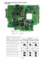
7. EXPLANATION OF MAIN / DRIVE PC BOARD
7-1. Main PCB
D301
S302 S304
DS1
S1
D2
Caution :
Please do not touch these switches by any means at the time of service
: Button Switch
: LED
Explanation of each part article of operation
Parts
Name
LED Display
Explanation of operation
S1
Reset switch for IC101
D2
Check for IC101 operation
Standby
Operation
Abnormal
IC101 failure
S302
Reset switch for IC301
S304
Reset switch for IC301
D301
Check for IC301 operation
DS1
Check for IC41 operation
IC301 failure
IC41 failure
2-8
7-2. Drive PCB
A
DS60
S601
Caution :
Please do not touch these switches by any means at the time of service
: Button Switch
: LED
Explanation of each part article of operation
Parts
Name
S601
DS601
A
Explanation of operation
LED Display
Standby
Operation
Abnormal
Reset switch for IC603
+5V failure
Check for +5V power-supply
IC301 failure
Check for IC603 operation
2-9
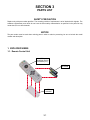
SECTION 3
PARTS LIST
SAFETY PRECAUTION
Replace only with part number specified. The mounting position of replacement is to be identical with originals. The
substitute replacement parts which do not have the same safety characteristics as specified in the parts list may
create shock, fire or other hazards.
NOTICE
The part number must be used when ordering parts in order to assist in processing, be sure to include the model
number and description.
1. EXPLODED VIEWS
1-1. Remote Control Unit
Y250
23306393 (E/U/X)
23306395 (C/Y)
Y251
23101988
AT03
23588637
3-1
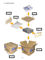
1-2. Packing Assembly
A403
23946137 (L)
A410
23918290
A404
23945102
A403
23946137 (R)
A400
23064421
A401
SEE PAGE XX
3-2
1-3. Accessories
PARTS NO
SN
FORM
PARTS NO
SN
Y250
23306393
Y250
23306395(Y/C)
Y251
23101988
Y200
23552948
Y201
Y201
Y201
Y201
Y215
Y216
Y207
Y208
Y209
Y210
Y210
Y210
Y211
Y211
Y212
23552949
23565184
23565186
23565187
23565185
23565183
23589193
23589194
23589195
23589179
23589196
23589198
23589180
23589197
23589181
23368750
Y102
RGB cable
23368731
Y104
FORM
USB cable
23368733
Y105
Audio cable for
Computer
23368676A
Y106
Control cable
(RS-232C)
Y110
Adapter for
Macintosh computer
23368679
23368732
Y240
AV cable
23372149
Y256
Power cord
(E/Y)
Y260
23372154
Y260
Y260
Power cord
(U)
3-3
23372145
Power cord
(E/Y/X)
23372155
Power cord
(C)
U-EF
E-EG
CHT
KOR
E-F/SP
U-SPA
GER
ITA
POR
ENG
CHT
KOR
FRA
CHS
SPA
1-4. Chassis Assembly
A203 : 23540388
TOP TAG
A100 : 23540383
TOP COVER
A241 : 23466925
AIR FILTER
B131 : 2352813
SPEAKER HOLDER
A210 : 23540385
REAR PANEL
SS01 : 23344463
SWITCH
A201 : 23436756
HANDLE
A242 : 23466926
AIR FILTER SHEET
B114 : 23890876
PUSH BUTTON CAP (L)
A240 : 23540362
AIR FILTER COVER
A220 : 23450321
FRONT PANEL
B115 : 23890877
PUSH BUTTON CAP (R)
A260 : 23540383
LAMP COVER
3-4
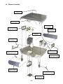
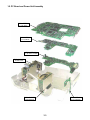
1-5. PC Board and Power Unit Assembly
E101 : 23771041
P.C.B, MAIN
E102 : 23771042
P.C.B, DRIVE
E103 : 23771043
P.C.B, VIDEO AUDIO
P800 : 23122399
POWER UNIT
P850 : 23122397
LAMP DRIVER
E104 : 23771044
P.C.B, SENSOR
3-5
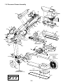
1-6. Document Camera Assembly
O
C
U
S
B386
F
B375
PC300
CAMERA ASSEMBLY
B372
B383
B382
B382A
B382B
B382C
(Inner spring)
B377
B380
B370
B366
P
P
B410
P
P
B363
B420
P
B362
B430
B400
P
B368
P
P
B358
E107
LED PC BOARD
W
W
W
W
B357
W
SC01
W
W
W
P
B320A
B320B
W
B351
B310 (Plastic assembly)
B320
B353
P
B310A (without below; )
button top
LED filter
remote filter
cushion (2 kinds)
B355
LOCK
W.BAL
AN
CE
STOR
E
GAIN
CAM
ARM
LIGHT
ERA
B350
B330
ARM ASSEMBLY
(without each plastic cover)
E106
CONECTION PC BOARD
Screw form
W
P
B470
no mark
3-6
1-7. Labels
A300
23564767 (X10)
23564820 (X11)
23564833 (X20)
23564834 (X21)
A301
23564766 (X10)
23564835 (X20)
TLP-X10
TLP-X10
LCD DATA PROJECTOR
TLP-X10
A312
23564942
A310
23564943
AUTO
SET
AUTO
KEYSTON
AUTO
KEYSTONE
VOL/ADJ.
INPUT
MENU
EXIT
MENU
ENTR
ENTER
ON/STANDBY
FAN
BUSY
ON
BUSY
TEMP
TEMP LAMP
A303
23564788 (10E)
23564768 (10U)
23564883 (10Y)
23564815 (11E)
23564814 (11U)
23564887 (11Y)
23564894 (20C)
23564892 (20E)
23564890 (20U)
23564893 (20Y)
23564900 (21C)
23564898 (21E)
23564896 (21U)
23564899 (21Y)
23564895 (20X)
23564901 (21X)
A314
23564946
A313
23564779 (U/E/X)
23564944 (C/Y)
3-7
A304
23564945
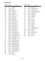
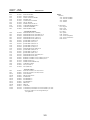
2. PARTS LIST
LOCATION
NUMBER
PARTS
NUMBER
DESCRIPTION
A100
A201
A203
A210
A220
A240
A241
A242
A260
A270
A290
A300
A300
A300
A300
A301
A301
A303
A303
A303
A303
A303
A303
A303
A303
A303
A303
A303
A303
A303
A303
A303
A303
A304
A310
A312
A313
A313
A314
A315
A320
A400
A401
A401
A401
A401
A401
A401
A401
A401
A401
A401
A401
A401
A401
A401
A401
A401
A403
A404
A410
AT03
23540383
23436756
23540388
23540385
23450321
23540362
23466925
23466926
23540386
23540416
23540474
23564767
23564820
23564833
23564834
23564766
23564835
23564788
23564768
23564883
23564815
23564814
23564887
23564894
23564892
23564890
23564893
23564900
23564898
23564896
23564899
23564895
23564901
23564945
23564943
23564942
23564779
23564944
23564946
23564947
23564903
23064421
23564785
23564769
23564873
23564818
23564817
23564874
23564879
23564870
23564869
23564875
23564880
23564872
23564871
23564876
23564881
23564882
23946137
23945102
23918290
23588637
- MECHANICAL PARTS TOP COVER
HANDLE
TOP TAG
REAR PANEL
FRONT PANEL
AIR FILTER COVER
AIR FILTER
AIR FILTER SHEET
LAMP COVER
LENS CAP
CONNECTOR COVER
FRONT TAG (X10)
FRONT TAG (X11)
RFONT TAG (X20)
FRONT TAG (X21)
REAR TAG(X10)
REAR TAG(X20)
RATING LABEL (10E)
RATING LABEL (10U)
RATING LABEL (10Y)
RATING LABEL (11E)
RATING LABEL (11U)
RATING LABEL (11Y)
RATING LABEL (20C)
RATING LABEL (20E)
RATING LABEL (20U)
RATING LABEL (20Y)
RATING LABEL (21C)
RATING LABEL (21E)
RATING LABEL (21U)
RATING LABEL (21Y)
RATING LABEL (20X)
RATING LABEL (21X)
CAUTION LABEL (BOTTOM)
CAUTION LABEL (TOP)
CAUTION LABEL (LAMP)
CAUTION LABEL (AC CORD)
CAUTION LABEL (AC CORD) for C
CAUTION LABEL (ARM)
CAUTION LABEL (LED)
VIDEO TERMINAL COVER for C
CARTON BOX
CARTON BOX LABEL (10E)
CARTON BOX LABEL (10U)
CARTON BOX LABEL (10Y)
CARTON BOX LABEL (11E)
CARTON BOX LABEL (11E)
CARTON BOX LABEL (11Y)
CARTON BOX LABEL (20C)
CARTON BOX LABEL (20E)
CARTON BOX LABEL (20U)
CARTON BOX LABEL (20Y)
CARTON BOX LABEL (21C)
CARTON BOX LABEL (21E)
CARTON BOX LABEL (21U)
CARTON BOX LABEL (21Y)
CARTON BOX LABEL (20X)
CARTON BOX LABEL (21X)
PACKING
COVER
PARTITION
BATTERY COVER
3-8
LOCATION
NUMBER
PARTS
NUMBER
B100
B105
B110
B114
B115
B131
B230
B310
B310A
B320
B320A
B320B
B330
B350
B351
B353
B355
B357
B358
B362
B363
B366
B368
B370
B372
B375
B377
B380
B382
B382A
B382B
B382C
B383
B386
B400
B410
B420
B430
B470
23411494
23540389
23436758
23890876
23890877
23528134
23528138
23540432
23540423
23890882
23890880
23890881
23890883
23540426
23540427
23540428
23540429
23549564
23549565
23549522
23549523
23549524
23549525
23549520
23549521
23549518
23129519
23549517
23540444
23540391
23540392
23836561
23890872
23540505
23890837
23549575
23549576
23549577
23936033
DESCRIPTION
BOTTOM CHASSIS
BOTTOM PIECE
FOOT ADJUST ASSEMBLY
PUSH BUTTON CAP (L)
PUSH BUTTON CAP (R)
SPEAKERE HOLDER
PC CARD HOLDER ASSEMBLY
DOCUMENT CAMERA ASSEMBLY
PROTECTION BAG
ASSEMBLY BASE
ARM BASE
1ST JOINT BASE
ARM ASSEMBLY
1ST JOINT M
1ST JOINT S
JOINT A
JOINT B
2ND JOINT A
2ND JOINT B
3RD JOINT 1A
3RD JOINT 1B
3RD JOINT 2A
3RD JOINT 2B
4TH JOINT A
4TH JOINT B
5TH JOINT A
5TH JOINT B
CAMERA BOTTOM COVER
FOCUS RING ASSEMBLY
FOCUS RING
LENS HOOD
SPRING
CAMERA BASE
CAMERA TOP COVER
LED CRUTCH BASE
LED JOINT
LED BACK
LED CLEAR
PLATE
LOCATION
NUMBER
PARTS
NUMBER
E101
E102
E103
E104
E106
E107
P800
P850
PC300
SS01
23771041
23771042
23771043
23771044
23771045
23771046
23122399
23122397
23771048
23344463
MAIN PC BOARD
DRIVE PC BOARD
VIDEO AUDIO PC BOARD
SENSOR UNIT
CONECTION PC BOARD
LED PC BOARD
POWER UNIT(APS-M317)
LAMP DRIVER(PHG201G7)
CAMERA ASSEMBLY
SWITCH(OHD3-130M)
Y200
Y201
Y201
Y201
Y201
Y207
Y208
Y209
Y210
Y210
Y210
Y211
Y211
Y212
Y215
Y216
Y250
Y250
Y260
Y260
Y280
Z100
Z101
23552948
23565184
23552949
23565186
23565187
23589193
23589194
23589195
23589179
23589196
23589198
23589180
23589197
23589181
23565185
23565183
23306393
23306395
23372154
23372155
23564821
23125888
23125889
- ACCESSORY PARTS OWNER'S MANUAL (CD-ROM)
OWNER'S MANUAL (ENG/GER) for E
OWNER'S MANUAL (ENG/FRA) for U
OWNER'S MANUAL (CHT) for C
OWNER'S MANUAL (KOR) for X
QUICK SHEET (GER) for E
QUICK SHEET (ITA) for E
QUICK SHEET (POR) for E
QUICK SHEET (ENG) for E
QUICK SHEET (CHT) for C
OWNER'S MANUAL (KOR) for X
QUICK SHEET (FRN) for E
QUICK SHEET (CHS) for C
QUICK SHEET (SPA) for E
OWNER'S MANUAL (ENG/SPA) for Y
OWNER'S MANUAL (SPA)
REMOTE CONTROL UNIT(CT-90057) for E/U/X
REMOTE CONTROL UNIT(CT-90066) for Y/C
POWER CORD (UL)
POWER CORD (GB250V10A)
COMMENT LABEL
FAN (TYF106J11)
FAN (D09T-12P)
E201
E201
E201A
E201B
E201C
E201D
E201E
E201F
E201G
E201H
E201I
E210G
E210G
23430891
23430901
23430892
23430893
23430894
23430895
23430896
23430897
23430898
23588634
23588635
23301384
23301390
DESCRIPTION
NOTES
(MODEL)
X20 : TLPX20/21 SERIES
X10 : TLPX10/11 SERIES
20X : TXPX20
21X : TXPX21
- OPTICAL PARTS OPTICAL ENGINE (CJ371TA) for X10
OPTICAL ENGINE (CJ374TA) for X20
MAIN FRAME
PROJECTION LENS
SUB FRAME
POLARIZER (R)
POLARIZER (G)
POLARIZER (B)
PBS PLATE
PBS FAN
LAMP FAN
LCD PANEL (P13XG210G or L3P13X-21G00G *) for X10
LCD PANEL (P13XG250G or L3P13X-25G00G *) for X20
* These type number is to be changed halfway of
mass production.
3-9
(LANGUAGE)
ENG : English
FRE : French
GER : German
ITA : Italian
SPA : Spanish
POR : Portuguese
CHS : Chinese (Simplified)
CHT : Chinese (Traditional)
KOR : Korean
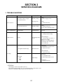
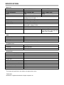
SPECIFICATIONS
Main Unit
Power requirements
Power consumption
Mass
Dimensions
Ambient environment
Lamp
Speaker
RGB INPUT
VIDEO INPUT
CONTROL terminal
Cabinet Material
Document camera
TLP-X10 / TLPX20
AC 100-240V 50/60Hz
320W (standby:18W )
5.3kg
W345mmxH104mmxD281mm
Temperature:0 to 35 cent degree
Humidity:30% to 70% HR
210W High pressure Hg lamp
2W (monaural)
RGB signal :(D-sub 15pin)
S-Video signal : Mini DIN-4pin
Video signal : 1V(p-p), 75 ohm
Mini DIN-8pin(RS-232C)
ABS
TLP-X11 / TLPX21
330W (standby:18W )
6.2kg
W345mmxH104mmxD336mm
1/2 inches CCD
1,447,680 pixels (1392x1040 dots)
Lens : F=3.1 f=6.4mm
LCD
Projection system
Panel size
Driving system
Picture elements
3-panel transmission
1.3 inches
TFT active matrix
786,432 pixels (1024x768dits)
Projection Lens
Lens
Focusing
Zooming
Zooming lens F=2.2-2.5 f=47-61mm
Manual operation
Manual operation
Accessories
Owner's manual
Owner's manual (CD-ROM)
Wireless remote control
Battery
Power cord
RGB cable
Adapter for Macintosh computer
AV cable
Audio cable for computer
Control cable
USB cable
1
1
1
2
1
1
1
1
1
1
1
(3m)
(3m)
(3m)
(1.8m)
(2m)
The design and specification are subject to change without notice.
Trademarks
Macintoh is a registered trademark of Apple computer, Inc.
1-1, SHIBAURA 1- CHOME, MINATO - KU, TOKYO 105 - 8001, JAPAN