1
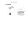
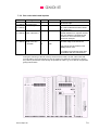
AXIOME
axm935
Optical Mark Reader
with Manual Document Feed
Technical Operating and
Service Manual
AXIOME
Table of Contents
1
1.1
1.1.1
1.2
1.2.1
1.3
1.3.1
1.3.2
1.3.3
Introduction .................................................................................................... 1-1
About this manual............................................................................................. 1-1
Typographical notes ......................................................................................... 1-1
Information about unpacking the mark reader................................................... 1-2
Scope of the delivery ........................................................................................ 1-3
Device related safety information...................................................................... 1-4
Conformity ........................................................................................................ 1-4
Precautionary measures for transportation, storage and installation ................. 1-4
Selection of the work site.................................................................................. 1-4
2
2.1
2.2
2.2.1
2.2.2
2.2.3
2.2.4
2.2.5
2.2.6
The axm935 mark reader................................................................................ 2-1
Design .............................................................................................................. 2-1
Document processing ....................................................................................... 2-3
Manual document guidance – automatic document intake................................ 2-3
Transport path .................................................................................................. 2-3
Read stations ................................................................................................... 2-4
Opening and closing the scanner cover ............................................................ 2-4
Document output .............................................................................................. 2-5
Display of the operating status.......................................................................... 2-5
3
3.1
3.2
3.3
3.4
3.4.1
3.4.2
3.5
3.5.1
3.5.2
3.6
3.7
Putting the mark reader into operation ......................................................... 3-1
Setting up the device ........................................................................................ 3-1
Mains connection data...................................................................................... 3-2
Data interface ................................................................................................... 3-3
PC connection .................................................................................................. 3-3
Minimum requirements on the PC..................................................................... 3-3
Connecting the reader and the PC.................................................................... 3-3
Software ........................................................................................................... 3-4
Interface firmware............................................................................................. 3-4
Read software .................................................................................................. 3-4
Testing the read functions ................................................................................ 3-4
De-installing the reader..................................................................................... 3-5
4
4.1
4.1.1
4.1.2
4.1.3
4.1.4
4.2
4.3
4.4
Adjusting and cleaning the reader ................................................................ 4-1
Setting the OMR read head .............................................................................. 4-1
Basic setting "standard document" ................................................................... 4-1
Adjusting the lateral setting of the OMR read head........................................... 4-2
Adjusting the lateral setting of the lower OMR read head (option) .................... 4-3
Effect of the read head setting on the scanning result....................................... 4-4
Setting the bar code read head (option)............................................................ 4-5
Cleaning the document transport path .............................................................. 4-6
Trouble shooting............................................................................................... 4-7
5
5.1
5.1.1
Test Program "OMR-Test" ............................................................................. 5-1
Main window..................................................................................................... 5-2
Functions in the menu bar ................................................................................ 5-2
Axiome Alpha SA
2
AXIOME
5.1.2
5.2
5.2.1
5.2.2
5.2.3
5.2.3.1
5.2.3.2
5.2.3.3
5.2.3.4
5.2.3.5
5.2.3.6
5.2.3.7
Functions of the switching buttons .................................................................... 5-3
"OMR - Test" window........................................................................................ 5-4
Functions in the menu bar ................................................................................ 5-4
Status display ................................................................................................... 5-7
Functions of the switching buttons .................................................................... 5-7
Reading out the firmware version ..................................................................... 5-8
Checking the OMR read head lighting .............................................................. 5-8
Checking the values of the light barriers ........................................................... 5-8
Testing the motor.............................................................................................. 5-9
Checking the speed.......................................................................................... 5-9
Read tests ........................................................................................................ 5-9
Output of the parameters of the serial interface .............................................. 5-11
6
6.1
6.2
6.2.1
6.2.2
6.2.3
6.2.4
6.2.5
6.3
6.4
6.5
6.5.1
6.5.2
6.6
6.7
Carrying out repairs ....................................................................................... 6-1
Disassembling the reader housing parts ........................................................... 6-2
Working on the driving mechanism ................................................................... 6-4
Replacing the driving belt for the feed roller (swivel roller) ................................ 6-4
Replacing the round belt of the drive motor ...................................................... 6-5
Replacing the toothed belt ................................................................................ 6-6
Replacing the silicone rings of the transport rollers........................................... 6-7
Replacing the counter-pressure rollers ............................................................. 6-8
Replacing the cable harness........................................................................... 6-10
Replacing the motor........................................................................................ 6-12
Working on the CPU board ............................................................................. 6-13
Disassembling and assembling the CPU board .............................................. 6-13
Setting the brightness values of the light barriers............................................ 6-14
Disassembling and assembling the power supply........................................... 6-15
Working on the read head .............................................................................. 6-16
7
7.1
7.2
7.2.1
7.2.2
7.2.3
7.2.4
7.3
7.3.1
7.3.2
7.3.3
7.3.4
Requirements on the documents .................................................................. 7-1
External characteristics..................................................................................... 7-1
Prescriptions and recommendations concerning OMR marks........................... 7-2
The mark field .................................................................................................. 7-2
Correct marks................................................................................................... 7-3
Inadmissible marks........................................................................................... 7-3
Reliable marking instruments............................................................................ 7-4
Axiome OMR document specifications ............................................................. 7-5
Standard document .......................................................................................... 7-5
Scanning window.............................................................................................. 7-7
Bar codes labels and imprints........................................................................... 7-8
Permissible document colors for red light and infrared light scanning ............... 7-9
8
List of the wearing parts and the spare parts............................................... 8-1
Axiome Alpha SA
3
AXIOME
1 Introduction
1.1 About this manual
This manual is intended for use by service personnel.
• Part 1 provides information about
– unpacking and storing the device and device related safety information
– connection to the mains source and authorization as well as
– the requirements on the operating environment.
• Part 2 informs you about the main mode of operation of the document reader
and provides tips on operation.
• Part 3 describes the setting up and installation of the axm935.
• Part 4 shows how you can increase the reading reliability of the axm935 by
mechanical adjustments and cleaning procedures.
• Part 5 describes the functions of the test program "OMR-Test".
• Part 6 shows how disorders can be eliminated by replacing defective parts.
• Part 7 contains the document specifications and information on the marks.
• Part 8 lists the wearing parts and the spare parts.
1.1.1 Typographical notes
Ị
This symbol calls your attention to particular items that absolutely must be
observed.
♦ This symbol always appears before process sequences and it simultaneously
indicates the chronological sequence.
Axiome Alpha SA
1-1
AXIOME
1.2 Information about unpacking the mark reader
The box inside the packaging
contains the document output tray.
♦ Grasp the reader by the filling
materials mounted on the left and
right sides of the device and lift it
carefully, straight upwards out of
the cardboard box without tilting
it. The device weighs about 6 kg.
♦ Set the reader down on the
intended work surface and
remove the two pieces of filling
material on the sides.
Ị
When setting up the reader, take care not to grasp the device at the top near
the (closed) scanner cover but only at the back housing cover and below at the
base plate.
The scanner cover is not locked! It could swing open dangerously which
might result in the device falling out of your hands onto the work surface!
Axiome Alpha SA
1-2
AXIOME
♦ Remove the output tray from the packaging and place it to the right of the
reader on the work desk.
You can read about how to set up the reader and how to mount the output tray in
section 3.1.
Ị
Save the entire original packing for later transportation and shipping of the
mark reader.
Devices that are sent back to suppliers for maintenance or repair work are
always returned in their original boxes (possibly at cost of the sender).
1.2.1 Scope of the delivery
Check to make sure that the delivery is complete. All accessories required for the
connection and operation of the axm935 are included in the delivery:
–
–
–
–
mains cable
data cable
CD ROM with installation software and manual
hexagon socket screw key 1.5 mm
If something is missing or if damages occurred during transportation, please
contact your supplier.
Axiome Alpha SA
1-3
AXIOME
1.3 Device related safety information
1.3.1 Conformity
The axm935 reader conforms to the CE standards and guidelines for data
processing devices (design according to VDE 0805/5.90, interference
suppression according to VDE 0871-B). It can be operated continuously under
normal room conditions.
1.3.2 Precautionary measures for transportation, storage and installation
Please observe the following points regarding the transportation and installation
of the reader:
Transportation and storage
Ị
Transportation of the reader should only be effected in the original packing. It
protects against shocks and inadmissible strains on the mechanical parts.
Ị
Please take the ambient conditions into consideration when transporting or
storing the reader.
Mains connection and authorization
Ị
The reader may only be operated when connected to a grounded shockproof
outlet. Industrially operated mains networks often exhibit substantial, loaddependent interference peaks (powerful motors, electrical welding plants, etc.).
The axm935 reader is protected against such interference to a great extent,
but if interference is present, try to use a network used for EDP or select a
mains supply that is free of interference.
Ị
Ị
Never open the housing of the reader and never remove any housing parts.
Ị
It is forbidden to effect changes or modifications to the reader that are not
stated in this manual. The manufacturer of the device will decline any form of
guarantee demand and will not accept any service clauses if it can be
demonstrated that the reader was manipulated or damaged by unauthorized
persons.
Always turn the reader off via the mains switch before carrying out any
adjustments or cleaning operations.
1.3.3 Selection of the work site
Take care to assure that the axm935 is exposed to appropriate operating
conditions. This is important in assuring faultless functioning of the reader:
Ị
The reader must stand on a stable, horizontal and level surface. It requires a
surface area of 450 x 220 mm as working space; the reader weighs 6.2 kg.
Vibrations at the work site should be avoided.
Axiome Alpha SA
1-4
AXIOME
Ị
Check to assure that the device is shielded as extensively as possible against
sources of heat such as direct sunlight, radiators, spotlights or other sources of
light that produce heat.
Sunlight or foreign sources of light applied to the scanning unit under
unfavorable circumstances may also have an influence on the read sensitivity.
Ị
Ị
The permissible relative humidity amounts to 40 - 60%, condensation-free.
Ị
The axm935 corresponds to the requirements regarding interference emission
and resistance to jamming (ESD) as specified by the CE guidelines. In order to
assure complete interference immunity, shielded data cables with connector
casings of metal or with metallic connector casings must be used.
Ị
Take care that the device is not operated in surroundings that are
contaminated by dust or oil. Air currents caused e. g. by windows that are
continually left open, by passageways or ventilators, may lead to the increased
production of dust and this in turn may necessitate shorter maintenance and
cleaning intervals.
Ị
The work site must afford sufficient space for the handling of the documents.
It must be possible to lay all cables (mains cable and data cable) without
buckling and without tensile stress. Take care to identify stumbling pitfalls.
Axiome Alpha SA
1-5
AXIOME
2 The axm935 mark reader
This chapter provides brief information about the performance characteristics and
the basic mode of operation of the mark reader.
2.1 Design
The axm935 mark reader is an optical mark reader designed for manual feed. It
reads marks, crosses, bars, dots and various other types of markings. It
processes automatically printed documents (e. g. laser printouts) as well as blind
color forms and qualitatively high-grade (dimensionally accurate) copies. The
read head can be folded back without the use of tools in order to carry out
cleaning or maintenance operations.
The compact structure of the device allows it to be positioned at a slant as an
ergonomic desktop model.
This figure shows the axm935 ready for operation:
4
5
2
3
1
1
2
3
4
5
Display of the operating status
Document guide
Motor-driven document intake
Hinged upper scanner cover
Document output
Axiome Alpha SA
2-1
AXIOME
This figure shows the axm935 with opened scanner cover with two OMR and two
bar code read heads:
8
9
8 Mark scanners (OMR)
9 Bar code read heads
Axiome Alpha SA
2-2
AXIOME
2.2 Document processing
2.2.1 Manual document guidance – automatic document intake
You place an individual document by hand onto the document guide. This
triggers a light barrier that starts the transport motor and the document is
automatically drawn in across a feed roller.
Feed roller
2.2.2 Transport path
The document that is drawn in is passed on by a transport roller to a read station
whereby it passes a second light barrier that in turn activates the read process.
The document is transported through the read station by means of two additional
rollers. When the end of the document passes the read station this is detected by
a third light barrier and the read process terminates.
The transport speed amounts to 800 mm/s. A special profile on the silicone rings
of the transport rollers causes the document to always remain exactly flush along
the guide piece as it passes through the read station.
The figure shows the document transport path (with opened scanner cover).
Axiome Alpha SA
2-3
AXIOME
2.2.3 Read stations
The mark read head is dustproof and selfcleaning. It operates with red light so that all
conventional types of marking media can be
employed. As an option, an infrared mark read
head for marks made by pencil and OCR
signers can be used.
The mark read head processes documents with
a mark density of 40 tracks (1/5" interval) or (as
an option) 48 tracks (1/6" interval). The read
head is insensitive to documents with wrinkles
and with “reflecting” marks, it adjusts
dynamically to the document colors and gray
scale values used and it possesses a dynamic
dirt masking feature.
Depending upon the requirements of the
application, the axm935 can be equipped with a
second OMR read head (for the simultaneous
reading of the rear side of the document), with
two bar code read heads and – via a mountable
scanner – for bar code reading in a crosswise
direction.
To protect against dirt, the read stations are
located behind protecting glass.
The read heads are visible after the scanner
cover has been opened.
2.2.4 Opening and closing the scanner cover
The scanner cover must only be
opened to clean the read stations
or to perform adjustment
operations:
♦ Open the scanner cover by
pushing lightly at the upper end
of the document intake. Carefully
swing the cover towards the front
until it lies on the work desk.
♦ To close it again, lift the cover
towards the front and then swing
it towards the back until you hear
Axiome Alpha SA
2-4
AXIOME
that the guide pin of the base plate has latched into place.
Ị
When opening or closing the cover, please do not allow it to fall onto the work
surface or backwards onto the base plate of the reader.
2.2.5 Document output
In the event of a faultless read result the document is output in the output tray.
If the read result is poor, the document will be rejected and reported in the
display of the operating status (see section 2.2.6). The faulty document is
transported through the read station back to the document guide where it can be
removed and inserted again for a renewed read attempt.
2.2.6 Display of the operating status
The following table shows the standard displays:
LED
Significance
Red
Green
off
blinking
off
steady-burning
After the insertion of a document.
steady-burning
steady-burning
A document has been drawn in, but the data has not
yet been called.
off
steady-burning
Document ejection.
Ị
Ready
The reader is waiting for a document.
Both LEDs blinking
simultaneously
The LEDs blink until the document has been
removed; then "Ready".
Both LEDs blinking
alternately
Transportation fault, document intake or ejection jam;
LEDs blink until the fault is eliminated (remove
document); then "Ready".
It is possible that other operating modes or display statuses are parameterized
by the application software. In that case, they are documented in a special
software description.
Axiome Alpha SA
2-5
AXIOME
3 Putting the mark reader into operation
This chapter describes how to set up the reader at the work site and how to
proceed with the installation – from connection to a host (PC) up to conducting a
test run.
3.1 Setting up the device
The mark reader can be operated either lying flat on the work surface or at a
slant in desktop form.
♦ To set up the device at a slant, fold out the support bow at the rear side of the
housing.
Axiome Alpha SA
3-1
AXIOME
To assure faultless operation, you must now mount the output tray:
♦ Place the output tray flush next to the reader so that the two fastening bolts of
the reader fit into the corresponding recesses of the output tray. Then tighten
the securing screw.
You can then install the reader.
3.2 Mains connection data
The power supply of the axm935 is designed for a wide voltage range from 100
to 240 V ~. The connected load amounts to 20 W.
Normally no special provisions or settings of the voltage supply are required for
operation. However, check whether the existing mains voltage actually
corresponds to the values on the type plate of the reader.
Axiome Alpha SA
3-2
AXIOME
3.3 Data interface
The serial interface of the reader is executed as a 9-pin socket terminal strip. The
simplest connection is a "three-wire" connection without hardware handshake.
Bridges on the side of the reader are not necessary. The basic parameterization
of the reader supports this operating mode.
Pin assignments
Pin
"three-wire" assignment complete assignment
Pin 2 TxD
TxD
Pin 3 RxD
RxD
Pin 5 SGND
GND
Pin 6
DTR (+12 V are present after "power on")
Pin 7
CTS
Pin 8
RTS (+12 V are present after INIT)
3.4 PC connection
3.4.1 Minimum requirements on the PC
The minimum requirements on the PC are fulfilled nowadays by any
commercially available system. If the test program "OMR-Test" is to be installed
(see chapter 5) then a CD drive must be connected.
3.4.2 Connecting the reader and the PC
♦ Run down the operating
system of the PC and turn
off the PC.
♦ Connect the mains cable to
the connector of the reader
and then plug the mains
plug into a mains outlet.
♦ Connect the interface cable
to a free RS232 connector
of the PC and secure the
data connector with the
screws provided for that
purpose.
Axiome Alpha SA
PC connector
Mains plug
Mains switch
3-3
AXIOME
♦ Connect the data cable to the connecting socket of the reader and secure the
connector here as well.
♦ Turn on the reader by means of the mains switch.
♦ Turn on the PC and run up the operating system.
3.5 Software
The control of the reader is effected by means of device-specific interface
firmware and – via the connected PC – by means of read software designed
according to the user application.
3.5.1 Interface firmware
The communication between the axm935 and the PC is controlled via the
interface firmware, consisting of
• the standard interface and
• the interpreter interface.
How to read out and set the interface parameters is described in separate
manuals.
3.5.2 Read software
The read program itself defines the processing of the marks and bar codes that
are read out on the PC. This program is always adapted to the respective
application of the axm935. How to install this software on your PC and how to
work with it is described in a separate manual.
3.6 Testing the read functions
Upon completion of the installation steps the reader is ready for operation and
you can test the reading of the marked documents. Check hereby if the reader
operates faultlessly and if all the functions are executed in accordance with the
intended practical usage. Conduct the test only with documents that you will
actually use in practical operation. In this regard, also note the document
specifications contained in section 7.3.
The special test program "OMR-Test" is also at your disposal for certain tests and
functional settings of the reader. The mode of operation of this test program is
described in chapter 5.
Axiome Alpha SA
3-4
AXIOME
3.7 De-installing the reader
♦ De-install the scanner software on the host PC if it is present.
♦ Run down the operating system of the PC and turn off the PC.
♦ Turn off the reader.
♦ Loosen and unplug the connectors of the data cable at the PC and at the
reader.
♦ Unplug the connectors of the reader mains supply cable.
Axiome Alpha SA
3-5
AXIOME
4 Adjusting and cleaning the reader
This chapter describes how you can set the document reader by means of simple
mechanical adjustments to correspond to the documents to be read. For these
operations you will need a hexagon socket screw key (1.5 mm). Moreover, it will
be demonstrated how you can increase the read accuracy by simple cleaning
operations.
4.1 Setting the OMR read head
In the manufacture and printing of mark documents a particular dimensional field
must be exactly adhered to. Besides this, the clock mark track and the marking
area must run exactly parallel to the edge of the document that is transported
along the document stopper during the read process. On documents that are
printed or cut askew, the clock mark track and the marking area are spread
across the entire document outside of the dimensional field. These deviations in
dimension can be compensated within a certain tolerance range by means of a
lateral “shifting” of the OMR scanning strip.
4.1.1 Basic setting "standard document"
The mark scanning is set at the factory to correspond to a "standard document".
The table below shows the distances (in mm) based on a sample of 40 track
scanning with mark spacing of 1/5". The dimensions A and H are decisive for the
correct lateral setting of the OMR read head. When these dimensions, due to
inaccurate printing or cutting of the documents, are smaller or larger (deviations
max. -1 to +3 mm), compensation can be achieved by corresponding adjustment:
Document stopper
min.
norm.
A
13.97
B
5.08
C
10
D
1
E
1.5
F
G
max.
4
3.0
10
H
7.62
I
5.08
The read head must be adjusted when marks (even quite solid marks) that do not
fill out the entire width of the mark field, are not scanned at all or are only
Axiome Alpha SA
4-1
AXIOME
scanned in an inaccurate manner. It is also typical that marks are recognized
although they are actually too short or are situated clearly off-center in the mark
field.
4.1.2 Adjusting the lateral setting of the OMR read head
♦ Open the scanner cover.
On the front side of the scanner cover there is an opening for the setting screw
of the scanning strip:
The position at which the document stopper is located during the read process
is designated by a reference line on the base plate of the read head:
Clock track
Reference line
Axiome Alpha SA
4-2
AXIOME
♦ Insert the hexagon socket screw key into the opening and turn it
–
–
clockwise: the scanning strip is set further away from the edge of the
document (edge with the clock mark), that is, away from the reference line.
counter-clockwise: the scanning strip is set closer to the edge of the
document (edge with the clock mark), that is, closer to the reference line.
With one rotation of the hexagon socket screw key the scanning strip is shifted
by 0.5 mm in the respective rotational direction. Additional information about
adjusting the scanning strip is to be found in section 4.1.4 “Effect of the read
head setting on the scanning result”.
♦ Subsequently conduct a test run with original documents to check the setting of
the read head.
4.1.3 Adjusting the lateral setting of the lower OMR read head (option)
♦ Open the scanner cover.
At the front of the lower scanner cover there is also an opening for the setting
screw for the adjustment of the scanning strip:
♦ Insert the hexagon socket screw key
into the opening and turn it
–
–
clockwise: the scanning strip is set
further away from the edge of the
document (edge with the clock
mark), that is, away from the
reference line.
counter-clockwise: the scanning
strip is set closer to the edge of the
document (edge with the clock
mark), that is, closer to the
reference line.
With one rotation of the hexagon
socket screw key the scanning strip
is shifted by 0.5 mm in the respective
rotational direction. Additional
information about adjusting the
scanning strip is to be found in
section 4.1.4 “Effect of the read head
setting on the scanning result”.
♦ Subsequently conduct a test run with
original documents to check the
setting of the read head.
Axiome Alpha SA
4-3
AXIOME
4.1.4 Effect of the read head setting on the scanning result
On the basis of examples of various mark types and mark positions the following
table shows how the scanning result is dependent upon the lateral setting of the
read head. The test points (examples 4, 5, 6, 7) are also to be found on the
DATAWIN test document, with the aid of which you can quickly obtain information
about the setting of the read head and accordingly correct the setting of the
scanning strip.
Marking examples:
Document edge (reference line)
Clock mark track
A*
B*
Scanning
strip is set
correctly.
Comments on the marking
Interval from
Interval from
scanning strip to scanning strip to
reference line
reference line too
too slight for
large for
document.
document.
Scanning
1
Correct
Accurate
Accurate
Accurate
2
Correct
Accurate
Accurate
Accurate
3
Correct
Accurate
No
No
4
Test point: middle
Accurate
No
No
5
Test point: lower edge
No
No
Yes
6
Test point: upper edge
No
Yes
No
7
Test point: upper & lower edges
No
Yes
Yes
8
Sloppy, bleeding mark
Inaccurate
No
Inaccurate
9
Bleeding mark
Inaccurate
Accurate
Inaccurate
Inaccurate
No
Accurate
10 Short, bleeding mark
(as with an old ball point pen)
*)
Ị
A
If the interval from the scanning strip to the reference line is too slight, enlarge
the size of the interval by turning the hexagon socket screw key clockwise.
Ị
B
If the interval from the scanning strip to the reference line is too large, reduce
the size of the interval by turning the hexagon socket screw key counterclockwise.
Axiome Alpha SA
4-4
AXIOME
4.2 Setting the bar code read head (option)
To achieve proper recognition of the bar code, the bar code read head must be
positioned over the area to be read – as far as possible in the middle – while the
document is being transported. You can easily check the setting of the bar code
read head and, if necessary, correct it:
♦ Open the scanner cover.
♦ Place one of the bar code documents to be processed on the scanning unit in
such a manner that the edge on which the clock track is located lies flush along
the reference line of the base plate. (This reference line identifies the position
at which the document stopper is located during the read process).
Clock track
Reference line
Bar code read head
Hexagon socket screw key
There is an opening located next to the window of the bar code read head; the
adjusting screw for the read head is behind this opening:
♦ Insert the hexagon socket screw key into the bore hole and by turning the key,
position the bar code read head above the middle of the bar code that is
printed or glued onto the document.
Axiome Alpha SA
4-5
AXIOME
4.3 Cleaning the document transport path
The axm935 is insensitive to a great degree to the usual "office dust". Only in the
case of very soiled documents or documents that have a rough surface may it be
necessary during the course of longer operation to clean the paper path.
Tools:
Ị
cleaning brush, spirits of wine, cleaning cloth
When you are working with spirits of wine, be sure that there are no
burning objects (cigarettes or similar) in the environment of the working
place.
♦ Turn off the reader and open the scanner cover.
♦ Blow forcefully with a breath of air to clean the transport path.
If necessary use the brush to loosen any stubborn, adhering dirt.
♦ Clean the protective glass surfaces of the read stations using a lint-free
cleaning cloth. If required, saturate it lightly beforehand with spirits of wine.
♦ Also clean the transport rollers with a cloth lightly saturated with spirits of wine.
Axiome Alpha SA
4-6
AXIOME
4.4 Trouble shooting
The following table shows problems that may arise and measures that you can
take to eliminate the errors.
Problem
Measure
Read errors
Recognition of the
marks is becoming
increasingly poorer.
♦ Check if the scanner is dirty.
If necessary, clean the covers (protective glass covers) of
the read heads (see section 4.3).
♦ Check if the lateral setting of the scanner is correct or if it
possibly should be adjusted (see section 4.1).
Marks are not
♦ Check if the edges of the documents are straight.
recognized, especially at ♦ Check if the transport rollers are dirty (see section 4.3).
the beginning and/or
end of the document.
Marks are recognized at
places where there are
no marks, especially at
the beginning and/or
end of the document.
♦ Check if the edges of the documents are straight.
♦ Check if the transport rollers are dirty (see section 4.3).
Document transport
The document placed on ♦ Check whether the application software is running. Is the
the intake guide is not
feed-in command from the PC missing or was the data of
drawn in.
a document previously read not called?
♦ Turn the reader off and after about 3 sec. turn it on again.
Start the PC again according to the software description.
A document was re♦ Lift the document briefly out of the intake guide and then
jected as "poor"; another
replace it again.
attempt is to be made to
read the document.
The document is drawn
in but is not scanned
completely.
The ejection behavior is
not defined.
♦ Check if the transport rollers are dirty (see section 4.3).
♦ Contact your supplier if you are using documents that
have clock marks that are wider than those prescribed and
that thus do not correspond to the document specification.
Document output
The document is drawn
in correctly, the read
data is transmitted to the
PC, but the reader does
not output the
document.
Axiome Alpha SA
Try the measures described above and if necessary:
♦ Clean all the light barriers in the transport path (see
section 4.3).
♦ Check if the interface cable is firmly connected.
If these measures still do not remedy the situation please
contact Axiome’s support:
Hotline: +41 32 732 18 18
Fax:
+41 32 732 18 00
E-Mail: [email protected]
4-7
AXIOME
5 Test Program "OMR-Test"
This chapter describes the method of operation, the structure and the functions of
the test program "OMR-Test" for the axm935 reader. The description
presupposes that the user has knowledge of the Windows environment along
with its control menus and commands via mouse and keyboard.
The test program "OMR-Test" enables you to check functions and settings of the
reader, whereby parameters can be read out of the flash ROM of the reader
control system and stored there again. The program is installed on the PC
(starting from Windows98).
Installing the program
To install the program you must be logged on as administrator.
♦ Terminate all applications running on the PC.
♦ Insert the program CD "OMR Reader Update-Tools" and click on "Start" >
"Run".
"Setup.exe" starts the usual Windows installation procedure.
The directory "OMR-Tool" is stored under "C:\Program\".
♦ You can subsequently place the program icon of the test
program on your desktop.
Pull the file "OMR_Tool.exe" from the directory "OMR-Tool"
onto your desktop.
You can then rename the icon, e. g. "OMR-Test".
Starting the program
♦ Click on "Start" > "Program" > "OMR-Tool" > "OMR-Tool"
or
♦ double click on the program icon on your desktop:
The main window will be opened (see section 5.1).
Axiome Alpha SA
5-1
AXIOME
5.1 Main window
The test program has a user surface that is typical of Windows. All the functions
can be activated directly via switching buttons from the main window.
Menus can be opened in the menu bar and their commands can be started or
activated by the mouse.
5.1.1 Functions in the menu bar
• File
"Exit" terminates the program.
• COM-Port
Sets the interface via which the reader is connected to the PC.
• Reader-change
Displays the possible types of readers. The reader that is connected – in this
case the "A50 (axm935)" – is displayed.
Axiome Alpha SA
5-2
AXIOME
• Version
Shows the version number of the test program.
–
"Help" informs you of the functions in the function bar.
5.1.2 Functions of the switching buttons
• Firmware
Loads a new or specific firmware version from the PC into the flash ROM of the
axm935.
• Parameter
Loads parameters e. g. after a change of the firmware version from the PC into
the flash ROM of the axm935.
The reader must be turned off before you start these load functions; after
starting the program, it prompts you to turn the reader on again.
• OMR-test
This button starts the test program with the window "OMR-Test".
• Exit
Terminates the test program.
Axiome Alpha SA
5-3
AXIOME
5.2 "OMR - Test" window
The operation of the test program is clear and simple, because in the OMR-Test
window all the functions can be activated directly via switching buttons. The
parameters that are read out are thereby output in a protocol window.
Menu bar
Status display
Protocol window
Switching buttons
for test functions
Menus can be opened in the menu bar and their commands can be started or
activated by the mouse.
5.2.1 Functions in the menu bar
• File
–
"Protocol-File open..."
Opens a window for the selection of a particular protocol file.
All the data sent from the reader is stored in the protocol files.
Axiome Alpha SA
5-4
AXIOME
Protocol files have the extension ".log".
–
"Protocol-File close"
Closes the protocol file
–
"Exit"
Terminates the program
• Utils
Axiome Alpha SA
5-5
AXIOME
–
"Controls"
Sets baud rate, data bits, stop bits, parity and protocol.
–
"Font"
Changes the character font and type size for the display in the protocol
window.
–
"Baud-automatic"
When the reader is turned on, its baud rate is automatically set to the baud
rate of the PC.
Axiome Alpha SA
5-6
AXIOME
• Edit
–
"Copy"
Copies the text marked in the protocol window into the intermediate storage
of the PC. You can then transfer the contents into an opened text file (.txt).
–
"Clear all"
Deletes the contents of the protocol window.
• ?
Shows help texts for the functions of the OMR-Tool.
5.2.2 Status display
In the status display you can see if the connected reader is turned on and if the
interface is active.
5.2.3 Functions of the switching buttons
Depending on the respective function of the
switching button, the parameters that are read
out are displayed in a protocol window.
You can store the contents of the protocol
window in a protocol file (.log), which you can
then e. g. send by email as information and for
clarification to the technician of your axm935
supplier.
Axiome Alpha SA
5-7
AXIOME
5.2.3.1 Reading out the firmware version
Clicking on the switching button "Version" causes the firmware version to be
displayed in the protocol window, e. g.:
5.2.3.2 Checking the OMR read head lighting
♦ Open the scanner cover of the reader.
♦ Click on "LED on" to turn on the lighting of the
OMR read head(s).
♦ Check whether all the LEDs are lit.
If this is not the case, notify your supplier.
♦ To turn the lighting off, click on "LED off".
This check is only possible for standard scanning
with red light.
5.2.3.3 Checking the values of the light barriers
You can cause the values of the light barriers in the transport path of the axm935
to be displayed (also see section 6.5.2 on this).
♦ Click on "LB value".
The parameters will be displayed in the protocol window, e. g.:
Axiome Alpha SA
5-8
AXIOME
Whereby the following apply: IT = Input Tray (potentiometer 1); bRH = before
Read Head (potentiometer 3); aRH = after Read Head (potentiometer 4).
5.2.3.4 Testing the motor
You can test the motor of the reader directly by
means of a switching button from the PC:
♦ Click on the switching button "Main-motor" to
start the motor.
♦ To stop the motor, click again on this switching
button.
5.2.3.5 Checking the speed
♦ To cause the display of the transport speed that is currently set, click on the
switching button “Speed-contr”.
5.2.3.6 Read tests
In case of problems you can test a document by means of three different read
functions:
• Switching button "Read HEX" (hexadecimal)
Output of the document data in the form in which the reader transfers the data
to the PC and to the read program.
• Switching button "Read Patt" (mark pattern)
Visualization of all the marks of the document that is read.
• Switching button "Read Scan" (repeated reading at short time intervals)
Checking of the position of the document in the transport path, in order e. g. to
detect documents that are printed or cut askew.
The read results will be displayed in the protocol window and can subsequently
be copied into a text file (see section 5.2.1).
Axiome Alpha SA
5-9
AXIOME
Example of hexadecimal output:
Example of pattern output:
Axiome Alpha SA
5-10
AXIOME
Example of scan output:
5.2.3.7 Output of the parameters of the serial interface
♦ Click on the switching button "Serial COM".
The currently valid interface parameters will be output, e. g.:
Axiome Alpha SA
5-11
AXIOME
6 Carrying out repairs
This chapter describes which wearing parts and spare parts of the axm935 you
can replace by yourself. The operations are arranged and structured according to
the functional groups and components of the reader.
• Remove the parts of the housing
• Repair work on the
– document intake
– document transport
– document output
– OMR scanner
– bar code reader
– electrical parts / electronics
Ị
Always interrupt the current supply before removing the rear panel of the
housing!
Unplug the mains plug before you begin work on the opened reader. All repair
operations may be carried out in an idle state only.
Axiome Alpha SA
6-1
AXIOME
6.1 Disassembling the reader housing parts
In order to replace certain system components and wear and spare parts of the
reader, you must possibly – depending upon the location of the mounting space
and of the electrical connection – remove different housing parts beforehand.
Tools:
cross-tip screwdriver (size 1)
Reader housing part "rear panel"
Ị
Before you remove the housing rear panel you must turn off the reader
and disconnect the mains plug!
♦ Remove the six countersunk head screws and lift off the rear panel.
Reader housing part "upper scanner cover"
Upper scanner cover
You must remove this part in order e. g. to replace the
OMR read head.
♦ Remove the two countersunk head screws on the
bottom side of the read head plate and lift off the
scanner cover.
Axiome Alpha SA
6-2
AXIOME
Disassembling components inside the housing
CPU
board
Transport motor
Power
supply
In order to access certain installed parts and connections inside the housing, it
may be necessary that you disassemble one or more of these components.
The respective assembly and disassembly operations are described in detail in
the following sections:
• Belts and transport rollers (section 6.2)
• Light barriers/cable harness (section 6.3)
• Transport motor (section 6.4)
• CPU board (section 6.5)
• Power supply (section 6.6)
Axiome Alpha SA
6-3
AXIOME
6.2 Working on the driving mechanism
6.2.1 Replacing the driving belt for the feed roller (swivel roller)
1
1
2
Tools:
Spare parts:
2
cross-tip screwdriver (size 1)
1 round belt ATX 40 x 2.6
How to insert the new round belt:
♦ Remove the rear panel of the housing (see section 6.1).
♦ Remove the torn belt from the housing.
♦ Unscrew the bearing block (1) and unscrew the bearing block of the feed roller
(2).
♦ Place the new belt around the respective roller pair and then screw tight the
bearing blocks.
Ị
Round belts are rather sensitive to cuts or nicks on the surface. Therefore, take
care to assure that the surface of the newly inserted belts is not damaged. The
belt would otherwise tear within a very short time.
♦ Remount the rear panel of the housing.
Axiome Alpha SA
6-4
AXIOME
6.2.2 Replacing the round belt of the drive motor
Screw
Tools:
Spare parts:
Screw
cross-tip screwdriver (size 1)
round belt ATX 52 x 2,6
How to insert the new round belt:
♦ Remove the rear panel of the housing (see section 6.1).
♦ Remove the torn belt from the housing.
♦ Unscrew the motor block with the drive rollers.
♦ Place the new belt around the respective roller pair and then refasten the
motor block with the screws again.
Ị
Round belts are rather sensitive to cuts or nicks on the surface. Therefore, take
care to assure that the surface of the newly inserted belts is not damaged. The
belt would otherwise tear within a very short time.
♦ Remount the rear panel of the housing.
Axiome Alpha SA
6-5
AXIOME
6.2.3 Replacing the toothed belt
Tools:
cross-tip screwdriver (size 1)
Spare parts:
toothed belt S2M-234
How to replace the toothed belt:
♦ Remove the rear panel of the housing (see section 6.1).
♦ Remove the torn belt from the housing.
♦ Unscrew the bearing block (see section 6.2.1) and the motor block with the
drive rollers (see section 6.2.2).
♦ Insert the new toothed belt and tighten again the motor block and bearing block
with the screws.
Ị
The toothed belt may not be bent or buckled!
♦ Remount the rear panel of the housing.
Axiome Alpha SA
6-6
AXIOME
6.2.4 Replacing the silicone rings of the transport rollers
Tools:
cross-tip screwdriver (size 1)
Spare parts:
silicone rings 24 mm with lip and recess on the side (groove)
How to replace the rings of the transport rollers:
♦ Remove the rear panel of the housing (see section 6.1).
♦ Unscrew the respective bearing block.
♦ Pull off towards the front the ring that is to be replaced from the transport
rollers and replace it by a new ring.
Ị
Take care to assure that the side of the ring on which the groove is located is
pointed towards the document guide (towards the bearing block).
♦ Retighten with the screws the bearing block that you removed.
♦ Check whether the ring rotates properly.
♦ Remount the rear panel of the housing.
Axiome Alpha SA
6-7
AXIOME
6.2.5 Replacing the counter-pressure rollers
Tools:
– cross-tip screwdriver (size 1)
– hexagon socket screw key 1.5 mm
Spare parts:
– counter-pressure roller 18 mm
– counter-pressure roller for feeding in, conical, 18 mm
How to replace defective counter-pressure rollers:
♦ Remove the rear panel of the housing (see section 6.1).
♦ Unscrew the document guide strip (7 screws (A), see the figure).
A
A
A
Axiome Alpha SA
A
A
A
B
A
6-8
AXIOME
♦ Unscrew the small holding board (B) for the two operating display LEDs and
pull the LEDs out of the bore hole.
♦ Disconnect the flat ribbon connector for the read head from the CPU.
♦ Carefully pull out the guide strip with the read head towards the front (see the
figure); you must lightly push the flat ribbon cable as well.
Ị
Be careful to assure that you do not lose the prism of the light barrier and the
small covering plate.
♦ Unscrew the axle of the defective counter-pressure roller with the hexagon
socket screw key and pull out the axle.
Ị
Take care in handling the distance disk.
♦ Pull off the defective roller and place the new roller onto the axle. (Don’t forget
the distance disk!)
♦ Insert the axle into the bore hole again and tighten it with the hexagon socket
screw key.
♦ Re-assemble the reader in reverse order.
Ị
Take care to assure that the prism of the light barrier and the small covering
plate are positioned correctly again before you push the guide strip back again
and fasten it.
♦ Remount the rear panel of the housing.
Axiome Alpha SA
6-9
AXIOME
6.3 Replacing the cable harness
If your trouble shooting indicates that a light barrier is defective, replace the entire
cable harness of the document reader with all its light barriers instead of only the
one defective light barrier. The structural parts of the three light barriers are
already partially soldered onto the cable harness:
• LB 1: "document presence in the intake tray" (LED and photo transistor)
• LB 3: "document presence before the scanner" (photo transistor)
• LB 4: "document presence after the scanner" (photo transistor)
LB4
LB3
LB1
The LED connectors of LB 3 and LB 4 (in each case on the read head side)
are plugged.
Tools:
– cross-tip screwdriver (size 1)
– soldering iron
Spare parts:
cable harness, 2 LEDs for LB 3 and LB 4
Axiome Alpha SA
6-10
AXIOME
How to replace the cable harness:
♦ Remove the rear panel of the housing (see section 6.1).
♦ Unplug the cable harness plug from the CPU board.
♦ Unsolder the motor connections. Note the polarity.
♦ Unscrew the structural parts of the light barriers that are soldered onto the
cable harness.
♦ Lift out the old cable harness, insert the new one and screw tight the structural
parts of the light barriers that are soldered onto the cable harness.
♦ Solder again the connections for the motor and for the display of the operating
status. Take care to observe the polarity.
♦ Connect the cable harness to the CPU board.
♦ Unscrew the scanner cover (see section 6.1).
♦ Remove the two LEDs next to the upper scanning strip and disconnect the
connecting plugs.
♦ Connect the new LEDs and plug the connecting leads again (polarity: red/red blue/blue).
♦ Check the signals of all the light barriers (in this regard, see sections 5.2.3.3
and 6.5.2).
♦ Remount the rear panel of the housing.
Axiome Alpha SA
6-11
AXIOME
6.4 Replacing the motor
Tools:
– cross-tip screwdriver (size 1)
– hexagon socket screw key 1.5 mm
– soldering iron
Spare parts:
direct-current motor 2338S 012S
How to replace the motor:
♦ Remove the rear panel of the housing (see section 6.1).
♦ Unsolder the motor connection. Note the polarity of the connection.
♦ Loosen the three screws at the front of the motor support and lift out the motor.
Be careful of the round belt.
♦ Unscrew the pulley from the motor shaft and unscrew the motor support.
♦ Refasten the pulley and insert the new motor.
Ị
Take care to assure that the contact spring for the derivation of the static
charge rests lightly on the brass ring.
♦ Resolder the motor connection. Take care to observe the polarity of the
connection.
♦ Reinsert the round belt.
Ị
Note:
As a functional check you can start the motor by means of the test program
(see section 5.2.3.4).
♦ Remount the rear panel of the housing.
Axiome Alpha SA
6-12
AXIOME
6.5 Working on the CPU board
6.5.1 Disassembling and assembling the CPU board
Tools:
cross-tip screwdriver (size 1)
♦ Remove the rear panel of the housing (see section 6.1).
♦ Unplug all the plug connections of the CPU board. If necessary, make notes of
the connections.
♦ Unscrew the three fastening screws and lift out the board.
♦ The steps in assembling the board are carried out in reverse order.
Ị
Before replacing the rear panel of the housing check that all the connecting
plugs are firmly connected.
♦ Remount the rear panel of the housing.
Axiome Alpha SA
6-13
AXIOME
6.5.2 Setting the brightness values of the light barriers
The potentiometers for setting the brightness values for the light barriers (LB 1,
LB 3 and LB 4) are located on the CPU board.
Tools:
–
–
cross-tip screwdriver (size 1)
small flat screwdriver
(for the potentiometer setting)
♦ Remove the rear panel of the
housing (see section 6.1).
♦ The arrangement of the
potentiometers is shown in the
adjacent figure.
4
♦ Turn the reader on.
Ị
Caution, be careful in handling
live parts (high-voltage)!
3
1
♦ Start the test program (see section 5.2.3.3) and by means of the respective
potentiometer, set the correct value for each light barrier.
♦ After you have finished making the settings, turn the reader off again and
replace the rear panel of the housing.
Axiome Alpha SA
6-14
AXIOME
6.6 Disassembling and assembling the power supply
Tools:
– cross-tip screwdriver (size 1)
– hexagon socket wrench 5.5 mm
Spare parts:
power supply ASTEC LPS43
Ị
Disconnect the power supply cable before you start working on the power
supply!
How to replace the power supply:
♦ Remove the rear panel of the housing (see section 6.1).
♦ Unscrew the four screws that hold the power supply cage in place.
♦ Note the connected cables and disconnect the cable connections.
♦ Unscrew the four distance bolts and lift out the power supply.
♦ Insert the new power supply and reconnect all the cables according to the
notes you made before, fastening the parts in reverse order.
♦ Replace the rear panel of the housing.
Axiome Alpha SA
6-15
AXIOME
6.7 Working on the read head
The OMR read head (possibly as option also equipped with a bar code read
head) consists of an optoelectronic board and an amplifier board. Service
operations on the read head are limited to exchanging these two boards. The two
boards are always replaced together, since they are tuned and electrically
coordinated to one another.
Amplifier board
Optoelectronic board
Tools:
– cross-tip screwdriver (size 1)
– hexagon socket wrench 4 mm
♦ Remove the upper cover plate (see section 6.1).
♦ Unplug all the plug connections of the amplifier board and remove the four
screws in the upper part of the amplifier board.
♦ Carefully lift out the board towards the top. It is connected to the optoelectronic
board lying below it by means of several pin connectors on its bottom side.
♦ Unscrew the four screws and the four distance bolts in the upper part of the
optoelectronic board and lift the board out.
♦ Insert the new optoelectronic board but do not yet tighten the screws.
♦ Align the optoelectronic board: Before tightening the screws, be sure that the
board is positioned exactly parallel in its installation space. Reference edge is
the right side of the board.
♦ Fasten the optoelectronic board with the screws and distance bolts.
♦ Carefully insert the amplifier board. Be careful of the pin connectors on the
bottom side of the board.
♦ Fasten the amplifier board with the four screws, reconnect all the leads and
reattach the upper cover plate.
Ị
Carry out the following tests before starting operation again:
– Test the lighting of the OMR read head (see section 5.2.3.2).
– Test the lateral setting of the OMR read head (see section 4.1.2).
– If present, test the setting of the bar code read head (see section 4.2).
Axiome Alpha SA
6-16
AXIOME
Working on the lower read head
The replacement of the optional lower read head is carried out in principle exactly
as that of the upper read head.
After mounting of the new lower read head, conduct the same tests as described
above for the upper read head. In addition you must adjust and align both read
heads with respect to one another.
Axiome Alpha SA
6-17
AXIOME
7 Requirements on the documents
This chapter describes the requirements on the documents to be processed and
provides tips on the marks to ensure smooth operation of the axm935.
7.1 External characteristics
Good quality of the documents to be processed is a necessary requirement in
achieving good read results. Certain minimum requirements must therefore be
observed.
Prerequisite for the accurate scanning of the marks affixed to the documents is
the correct and unimpaired document transport through the scanning equipment
of the reader.
Moreover, the external characteristics of the documents to be read are important:
Ị
Do not insert any wrinkled, rolled or folded documents into the reader.
If necessary, smooth out the document beforehand and eliminate any dogears.
Ị
The use of correction fluids is forbidden!
Nevertheless, in the event that a document was treated with correction fluid,
please assure that the fluid has dried completely. Otherwise there is danger
that dirt may pass into the transportation mechanism and into the scanning unit
which could lead to reading inaccuracies.
Ị
Improperly glued bar code labels may also cause transportation disturbances.
Therefore, please press down the edges of the labels firmly.
Axiome Alpha SA
7-1
AXIOME
7.2 Prescriptions and recommendations concerning
OMR marks
7.2.1 The mark field
Read track 2
Mark field (print on the document)
Shadow mask of the mark scanning
Read track 1
Read window (theoretical)
Clock mark (print on the document))
Transportation direction
Edge of the document
The mark field identifies the position of the mark on the document. Inside the
mark field the position of the scanning window is determined by
–
–
–
the grid size of the mark scanning specified by the reader
(here 1/5” interval from one read track to the next read track),
the clock mark width (document design) and
the size and form of the scanning mask (shadow mask).
Axiome Alpha SA
7-2
AXIOME
7.2.2 Correct marks
A shadow mask with a diameter of 1 mm is used in the axm935. This ensures the
exact separation of the individual tracks and at the same time it enables the
acquisition of marking crosses. Moreover, because of the scanning that strongly
emphasizes the middle section, miscut documents, off-center marks and marks
that protrude are compensated for by means of generous tolerances. However,
for this it is prerequisite that the entire mark field is utilized for the marks:
Both the position and the size of the read window can be influenced to a great
extent by means of the parameterization of the reader in the interface program.
Ị
As basic principle however, the following applies: a mark can be recognized
only in the read window depicted above. Therefore, the better that the mark
field is filled by the mark (bar, cross) across the entire length, the more
accurately will this mark be recognized under unfavorable circumstances
(unsteady document transport, documents cut or printed off straight). And also
– the firmer the mark is, the more accurately can the automatic interference
masking select a mark and distinguish it from surrounding document dirt.
7.2.3 Inadmissible marks
Several typical marking errors are displayed here:
Ị
Continuous marks are not permissible!
A white interval of at least 1 mm must be maintained between the marks.
Axiome Alpha SA
7-3
AXIOME
7.2.4 Reliable marking instruments
The table below shows which marking instruments are best suited for red light
and infrared (option) scanning.
Utilized Signal
Marking instrument
Infrared scanning
Red light scanning
very good
very good
good
good
Pentel marker
useless
very good
Staedler 318
useless
very good
Ball point pen black
dubious
good
Ball point pen blue
useless
good
Ball point pen green
useless
good
Ball point pen red
useless
useless
Endorsing ink violet
no signal
dubious
Endorsing ink blue
no signal
very good
Toner *
very good
very good
Printing ink *
very good
very good
Pencil HB
Pencil H
* for preprinted marks, e. g. document type
The clock mark is always scanned with infrared light, independent of the signal
utilized by the mark scanning.
Axiome Alpha SA
7-4
AXIOME
7.3 Axiome OMR document specifications
7.3.1 Standard document
Standard document 40 tracks, spacing 1/5"
(All dimensions in mm)
min.
A
B
C
D
E
F
G
H
I
Axiome Alpha SA
norm.
max.
13.97 2 )
5.08
10
1
1.5 1 )
4
3.0
10
7.62 2 )
5.08
7-5
AXIOME
Standard document 48 tracks, spacing 1/6"
(All dimensions in mm)
min.
A
B
C
D
E
F
G
H
I
1
2
norm.
11.43 2 )
4.23
10
1
1.5 1 )
max.
4
3.0
10
8.89 2 )
3.81
) Can be smaller for special coding techniques, according to the manufacturer.
) DATAWIN mark readers permit a scanning shift of -1 +3 mm.
However, the dimensions A and H must then deviate in the same direction and by the
same values.
Document quality
Mechanical properties as per DIN 6723/6724
Optical features: OCR quality as per DIN 66223
PCS value for clock marks: > 60%
Document format
For all types of OMR: length in transport direction > width!
2
Type of
reader
OMR 50E
Axiome Alpha SA
Min. document
(mm)
100 x 40
Max. document
(mm)
320 x 220
Paper weight (g/m )
As per DIN 19307
80 - 140
7-6
AXIOME
7.3.2 Scanning window
Mark field
(document design)
Spacer frame
(not visible)
Theoretical scanning range
Clock track
Dimensions: A = min. 1.0 mm
B=
1.0 mm
C = min. 0.5 mm
Marks (and readable print on
documents) are recognized in the
"theoretical scanning range"
shown on the left.
If no specific scanning procedures
are used to mask black print (scan
mode, window definition), it is
recommended that no readable
inscriptions and graphics be
applied in the area of the displayed "spacer frame".
The spacer frame is dimensioned
in such a manner that minor deviations in document design, cut
and transport are compensated.
Axiome Alpha SA
7-7
AXIOME
7.3.3 Bar codes labels and imprints
Dimension
Designation
A
Distance to
(s. sketch) document end
B
White margin
(s. sketch)
Min. mm
Max. mm
35
–
10
C
Distance between 11
(s. sketch) 2 bar code tracks
D
Distance to lower
(s. sketch) edge of the doc.
– axm935
20
–
55
Comment
Distance of last bar code module to
document edge
Area before the first and after the last
bar code module that must be white
or in blind print
Only for "double bar code" option.
Greater distances on request. Please
note: the distance requested by the
customer is set in the factory and
cannot be changed.
Distance of the bar code module to
the lower edge of the document.
195
The area of the clock marks must
always remain free!
* Possible in exceptional cases after
consultation with the manufacturer
During the scanning of the bar code by the document reader, the bar code read head
must be able to scan the whole bar code in at least one diagonal. Therefore it is best in
any case to print the bar code as high as possible in order e. g. to be able to compensate
gluing inaccuracies.
Axiome Alpha SA
7-8
AXIOME
7.3.4 Permissible document colors for red light and infrared light scanning
Measurements with blind colors of the ink manufacturer "Zeller & Gmelin"
(% specification corresponds to the blind color unwanted signal)
Scanning:
Print color
Color no.
infrared light: 950 nm
Value
%
Comment
< 1
red light: 635 nm
Value
%
Comment
paper
white
<1
yellow
63376
3
good
4
still good
yellow
64400
3
good
4
still good
yellow
64401
< 1
very good
<1
orange
63079
2
very good
4
red
62429
2
very good
<1
red
63082
2
very good
4
still good
red
63112
2
very good
4
still good
red
65108
< 1
very good
<1
red
65204
< 1
very good
4
still good
red
65205
2
very good
4
still good
violet
63081
3
good
12
dubious
blue
62432
3
good
44
useless
blue
63893
2
very good
32
useless
blue
65107
2
very good
16
poor
blue-green
63892
3
good
44
useless
blue-green
65109
< 1
very good
24
useless
green
62431
3
good
48
useless
green
63483
< 1
very good
44
useless
green
63505
3
good
36
useless
green
64513
3
good
80
useless
yellow-green
63891
3
good
48
useless
brown
62433
4
still good
16
poor
brown shade
2
(1 g/m )
18482
2
very good
24
useless
brown shade
2
(2 g/m )
18482
2
very good
40
useless
very good
good
very good
very good
The blind color "violet", classified under red light as "dubious" should be avoided
if possible or only used after consultation with the manufacturer!
Axiome Alpha SA
7-9
AXIOME
8 List of the wearing parts and the spare parts
W/S
Article no.
Designation
W
01.002.02007 Round belt ATX 52 x 2.6
1 pc. (for drive motor)
W
01.002.02005 Round belt ATX 40 x 2.6
1 pc. (for feed roller/swivel roller)
S
01.002.05001 Toothed belt S2M-234
1 pc.
S
01.004.01001 D.C. motor 2338S 012S
with ball bearing
1 pc.
S
02.007.02004 Power supply ASTEC LPS43 (12 V, 40 W)
1 pc.
S
09.A50.00008 Cable harness with all light barrier
component parts
including 2 separate light barrier LEDs with
plug connectors
1 pc.
S
03.R08.00016 Silicone ring with lip and recess on the side
(groove)
for transport rollers, 24 mm
4 pcs.
Axiome Alpha SA
Figure
8-1
AXIOME
W/S
Article no.
Designation
S
07.A3300001 Counter-pressure roller, conical, 18 mm
1 pc.
S
03.A60.00064 Counter-pressure roller, 18 mm
3 pcs.
Axiome Alpha SA
Figure
8-2
AXIOME
AXIOME Alpha SA
Rue du Chasselas 1
CH-2034 Peseux
Swit zer land
e-mail: [email protected]
http://www.axiome.ch
Tel.
Fax.
Peseux
Basel
Zurich
Bern
Geneva
++41 (0) 32 732 18 18
++41 (0) 32 738 18 00
Printed in Switzerland by AXIOME SA
Axiome Alpha SA
8-3