1
®
Operating instructions
Linear feeder
SLL 175
SLL 400
SLL 800
SLL 804
SLF 1000
BA
Rhein-Nadel Automation GmbH
Rhein - Nadel Automation GmbH
VT-BA-SLL-SLF-GB
1
Stand 22.05.2012
Table of content
1
Technical data
page
3
2
Safety instructions
page
7
3
Construction and function of the linear feeder
4
Transport and mounting
page
9
5
Starting/ Adjustment
page
9
6
Specifications for the design of the track
page
15
7
Maintenance
page
16
8
Stockkeeping of spare parts and after-sales service
page
16
9
What to do, if....?
page
16
page
8
Instructions for trouble-shooting
Declaration of conformity
as defined by
Low voltage directive 2006/95/EC
Herewith we declare that the product complies with the following provisions:
Low voltage directive 2006/95/EC
applied harmonized standards:
DIN EN 60204 T1
remarks:
We assume that our product is to be integrated in a fixed machine. The provisions of the EMC directive 2004/108/EC has to be considered by the user.
Rhein-Nadel-Automation
-------------------------------Managing Director
Jack Grevenstein
Rhein - Nadel Automation GmbH
VT-BA-SLL-SLF-GB
2
Stand 22.05.2012
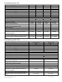
1 Technical data
Notice
All linear feeders listed in the table may only be operated in connection with a RNA control unit at a
mains voltage of 230V/50Hz.. Special voltages and frequencies see separate data sheet.
Pin assignment
With bridge: The bridge has to be installed in
connection 3 + 4
Linear feeder type SLL 175
Linear feeder type
SLL 175-175
SLL 175-250
Dimensions L x B 2) x H (mm)
Weight
Insulation type
Connecting cable length (m)
1)
Power consumption (VA)
1)
Current consumption (A)
1)
Magnet nominal voltage / Frequency (V / Hz)
200x62x63
1,2
IP54
1.800
16
70 mA
200/50
1
275x62x63
1,4
IP54
1.800
16
70 mA
200/50
1
Number of magnets
Magnet type
Magnet colour
Air gap (mm)
Vibration frequency Hz
Number of spring assemblies
Standard no. of springs
Number per spring assembly
Spring dimensions (mm)
Length (gauge for boreholes) x width
Spring size (mm)
Quality of the spring fastening screws
Tightening moment of the spring fastening screws
Max. weight of the oscillating units (linear track)
dependent on the mass moment of inertia and required running speed
Max. track length (mm)
Max. useful weight of the linear feeder dependent on
the mass moment of inertia and required running
speed
Rhein - Nadel Automation GmbH
VT-BA-SLL-SLF-GB
WZAW010
black
1,0
100 Hz
2
1x1,25 / 1x1,5/ 1x1,0 / 1x0,75
3
1,0
2
2x1,25 / 1x1,5/ 1x1,0 /
1x0,75
44,3(35)x26,7(12)
44,3(35)x26,7(12
0,75 – 1,5
8.8
300 Ncm
0,75 – 1,5
8.8
300 Ncm
1300 g
1500 g
325
400
400 – 500 g
500 – 600 g
Stand 22.05.2012
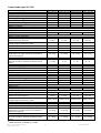
Linear feeder type SLL 400
Linear feeder type
Dimensions L x B 2) x H (mm)
Weight
Insulation type
Connecting cable length (m)
1)
Power consumption (VA)
1)
Current consumption (A)
1)
Magnet nominal voltage / Frequency (V / Hz)
SLL 400 - 400
SLL 400 - 600
SLL 400 - 800
SLL 400 - 1000
430 x 84 x 103
630 x 84 x 103
830 x 84 x 103
1030x84x103
6,5
IP 54
1,5
120
0,6
200 / 50
1
Number of magnets
Magnet type
Magnet colour
Air gap (mm)
Vibration frequency Hz
Number of spring assemblies
Standard no. of springs
Number per spring assembly
Spring dimensions (mm)
Length (gauge for boreholes) x width
8
10
IP 54
IP 54
1,5
1,5
120
120
0,6
0,6
200 / 50
200 / 50
1
1
WZAW 040
black
1,0
1,0
100 Hz
2
3
2 x 2,0
2 x 2,0
4 x 3,0
4 x 3,0
1,0
2
2 x 2,0
3 x 3,0
Spring size (mm)
Quality of the spring fastening screws
Tightening moment of the spring fastening screws
Max. weight of the oscillating units (linear track)
dependent on the mass moment of inertia and required running speed
Max. track length (mm)
Max. useful weight of the linear feeder dependent on
the mass moment of inertia and required running
speed
12,5
IP 54
1,5
120
0,6
200 / 50
1
1,0
4
3 x 2,0
5 x 3,0
70(56) x 40(18)
70(56) x 40(18)
70(56) x 40(18)
70(56) x 40(18)
2,0 und 3,0
8.8
15 Nm
2,0 und 3,0
8.8
15 Nm
2,0 und 3,0
8.8
15 Nm
2,0 und 3,0
8,8
15 Nm
ca. 5 kg
ca. 6 kg
ca. 7 kg
ca. 8 kg
700
900
1.100
1.300
1,5 – 2 kg
1,5 – 2 kg
1 - 1,5 kg
1 – 1,5 kg
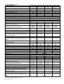
Linear feeder type SLF 1000
Linear feeder type
SLF 1000-1000
SLF 1000-1500
Dimensions L x B 2) x H (mm)
Weight
Insulation type
Connecting cable length (m)
1)
Power consumption (VA)
1)
Current consumption (A)
1)
Magnet nominal voltage / Frequency (V / Hz)
1.100 x 244 x 178
1.600 x 244 x 178
62
IP 54
2
504
2.51
200 / 50
2
80
IP 54
2
1.004
5,0
200 / 50
4
Number of magnets
Magnet type
Magnet colour
Air gap (mm)
Vibration frequency Hz
Number of spring assemblies
Standard no. of springs
Number per spring assembly
YZAW 080
red
2,5
Spring dimensions (mm)
Length (gauge for boreholes) x width
Spring size (mm)
Quality of the spring fastening screws
Tightening moment of the spring fastening screws
Max. weight of the oscillating units (linear track)
dependent on the mass moment of inertia and required running speed
Max. track length (mm)
Max. useful weight of the linear feeder dependent on
the mass moment of inertia and required running
speed
Rhein - Nadel Automation GmbH
VT-BA-SLL-SLF-GB
2,5
50 Hz
4
2
8 x 3,5
3 (4)³
12 x 3,5
128(108) x 160(2x60)
128(108) x 160(2x60)
3,5
8.8
60 Nm
3,5
8.8
60 Nm
ca. 40 kg
ca. 70 kg
2.000
2.500
20 – 30 kg
40 – 50 kg
Stand 22.05.2012
Linear feeder type SLL 800
Linear feeder type
SLL 800 - 800
SLL 800 - 1000 SLL 800 - 1200 SLL 800 - 1400
Dimensions L x B 2) x H (mm)
Weight
Insulation type
Connecting cable length (m)
1)
Power consumption (VA)
1)
Current consumption (A)
1)
Magnet nominal voltage / Frequency (V / Hz)
850 x 120 x 162
1.050 x 120 x 162
18,5 kg
IP 54
2
251
1,26
200 / 50
1
Number of magnets
Magnet type
Magnet colour
Air gap (mm)
Vibration frequency Hz
Number of spring assemblies
Standard no. of springs
Number per spring assembly
Spring dimensions (mm)
Length (gauge for boreholes) x width
Spring size (mm)
Quality of the spring fastening screws
Tightening moment of the spring fastening screws
Max. weight of the oscillating units (linear track)
dependent on the mass moment of inertia and required running speed
3,0
2
1 x 2,5
5 x 3,5
Max. track length (mm)
Max. useful weight of the linear feeder dependent on
the mass moment of inertia and required running
speed
1)
2)
1.250 x 120 x 162
20,5 kg
23,5 kg
IP 54
IP 54
2
2
251
251
1,26
1,26
200 / 50
200 / 50
1
1
YZAW 080
red
3,0
3,0
50 Hz
2
2
1 x 2,5
1 x 2,5
5 x 3,5
6 x 3,5
1.450 x 120 x 162
24,0 kg
IP 54
2
251
1,26
200 / 50
1
3,0
2
1 x 2,5
6 x 3,5
108(90) x 55(25)
108(90) x 55(25)
108(90) x 55(25)
108(90) x 55(25)
2,5 ; 3,5
8.8
30 Nm
2,5; 3,5
8.8
30 Nm
2,5; 3,5
8.8
30 Nm
2,5; 3,5
8.8
30 Nm
ca. 11 kg
ca. 13 kg
ca. 15 kg
ca. 17 kg
1.100
1.300
1.500
1.700
4 - 8 kg
4–8
6 - 10
6 - 10
Linear feeder type
SLL 800 - 1600 SLL 800 - 1800 SLL 800 - 2000 SLL 804 - 2400
Dimensions L x B 2) x H (mm)
Weight
Insulation type
Connecting cable length (m)
1)
Power consumption (VA)
1)
Current consumption (A)
1)
Magnet nominal voltage / Frequency (V / Hz)
1.650 x 120 x 162
31,5
IP 54
2
251
1,26
200 / 50
1
Number of magnets
Magnet type
Magnet colour
Air gap (mm)
Vibration frequency Hz
Number of spring assemblies
Standard no. of springs
Number per spring assembly
Spring dimensions (mm)
Length (gauge for boreholes) x width
Spring size (mm)
Quality of the spring fastening screws
Tightening moment of the spring fastening screws
Max. weight of the oscillating units (linear track)
dependent on the mass moment of inertia and required running speed
Max. track length (mm)
Max. useful weight of the linear feeder dependent on
the mass moment of inertia and required running
speed
3,0
3
2 x 2,5
7 x 3,5
1.850 x 120 x 162
2.050 x 120 x 162
34,0
39,5
IP 54
IP 54
2
2
251
251
1,26
1,26
200 / 50
200 / 50
1
1
YZAW 080
red
3,0
3,0
50 Hz
3
3
2 x 2,5
2 x 2,5
7 x 3,5
9 x 3,5
2.450 x 120 x 172
63
IP 54
2
502
2,51
200 / 50
2
3,0
4
2 x 2,5
14 x 3,5
108(90) x 55(25)
108(90) x 55(25)
108(90) x 55(25)
108(90) x 55(25)
2,5; 3,5
8.8
30 Nm
2,5; 3,5
8.8
30 Nm
2,5; 3,5
8.8
30 Nm
2,5; 3,5
8.8
30 Nm
ca. 19 kg
ca. 21 kg
ca. 23 kg
ca. 51 kg
1.900
2.100
2.300
2.700
6 – 10 kg
6 – 10 kg
6 – 10 kg
10 – 12 kg
At special connecting values (voltage/frequency see type plate at the magnet
Width dimension for design b (= wide)
Rhein - Nadel Automation GmbH
VT-BA-SLL-SLF-GB
5
Stand 22.05.2012
Linear feeder type SLL 804
Linear feeder type
Dimensions L x B 2) x H (mm)
SLL 804 - 800
850 x 120 x
172
21,5
IP 54
2
251
1,26
200 / 50
1
Weight
Insulation type
Connecting cable length (m)
Power consumption 1) (VA)
Current consumption 1) (A)
Magnet nominal voltage 1) / Frequency (V / Hz)
Number of magnets
Magnet type
Magnet colour
Air gap (mm)
Vibration frequency Hz
Number of spring assemblies
Standard no. of springs
Number per spring assembly
Spring dimensions (mm)
Length (gauge for boreholes) x width
3,0
2
1 x 2,5
6 x 3,5
Spring size (mm)
Quality of the spring fastening screws
Tightening moment of the spring fastening screws
Max. weight of the oscillating units (linear track)
dependent on the mass moment of inertia and required running speed
Max. track length (mm)
Max. useful weight of the linear feeder dependent on
the mass moment of inertia and required running
speed
Linear feeder type
Dimensions L x B 2) x H (mm)
SLL 804 - 1000 SLL 804 - 1200 SLL 804 - 1400
1.050 x 120 x
1.250 x 120 x
1.450 x 120 x
172
172
172
24,5
27,5
29,5
IP 54
IP 54
IP 54
2
2
2
251
251
251
1,26
1,26
1,26
200 / 50
200 / 50
200 / 50
1
1
1
YZAW 080
red
3,0
3,0
3,0
50 Hz
2
2
2
2 x 2,5
4 x 2,5
2 x 2,5
5 x 3,5
6 x 3,5
8 x 3,5
108(90) x
55(25)
2,5 / 3,5
108(90) x
55(25)
2,5 / 3,5
108(90) x
55(25)
2,5 / 3,5
108(90) x
55(25)
2,5 / 3,5
8.8
30 Nm
8.8
30 Nm
8.8
30 Nm
8.8
30 Nm
21 kg
25 kg
28 kg
32 kg
1.100
1.300
1.500
1.700
12 – 15 kg
12 – 15 kg
12 – 15 kg
12 – 15 kg
SLL 804 - 1600 SLL 804 - 1800 SLL 804 - 2000 SLL 804 - 2800
1.650 x 120 x
1.850 x 120 x
2.050 x 120 x
2.850 x 120 x
172
172
172
172
39,5
43,0
49,5
76
IP 54
IP 54
IP 54
IP 54
2
2
2
2
502
502
502
502
2,51
2,51
2,51
2,51
200 / 50
200 / 50
200 / 50
200 / 50
2
2
2
2
YZAW 080
red
3,0
3,0
3,0
3,0
50 Hz
3
3
3
4
4 x 2,5
4 x 2,5
4 x 2,5
2 x 2,5
9 x 3,5
9 x 3,5
11 x 3,5
14 x 3,5
Weight
Insulation type
Connecting cable length (m)
Power consumption 1) (VA)
Current consumption 1) (A)
Magnet nominal voltage 1) / Frequency (V / Hz)
Number of magnets
Magnet type
Magnet colour
Air gap (mm)
Vibration frequency Hz
Number of spring assemblies
Standard no. of springs
Number per spring assembly
Spring dimensions (mm)
Length (gauge for boreholes) x width
108(90) x
55(25)
2,5; 3,5
8.8
30 Nm
108(90) x
55(25)
2,5; 3,5
8.8
30 Nm
Spring size (mm)
Quality of the spring fastening screws
Tightening moment of the spring fastening screws
Max. weight of the oscillating units (linear track)
36 kg
40 kg
dependent on the mass moment of inertia and required running speed
1.900
2.100
Max. track length (mm)
Max. useful weight of the linear feeder dependent on
12 – 15 kg
12 – 15 kg
the mass moment of inertia and required running
speed
1)
At special connecting values (voltage/frequency see type plate at the magnet
2)
Width dimension for design b (= wide)
Rhein - Nadel Automation GmbH
VT-BA-SLL-SLF-GB
6
108(90) x
55(25)
2,5; 3,5
8.8
30 Nm
108(90) x 55(2)
44 kg
ca. 62 kg
2.300
3.100
12 – 15 kg
10 – 12 kg
2,5; 3,5
8.8
30 Nm
Stand 22.05.2012
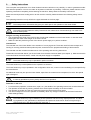
2.
Safety instructions
The conception and production of our linear feeders has been carried out very carefully, in order to guarantee troublefree and save operation. You too can make an important contribution to job safety. Therefore, please read this short
operating instructions completely, before starting the machine. Always observe the safety instructions!
Make sure that all persons working with or at this machine carefully read and observe the following safety instructions!
This operating instruction is only valid for the types indicated on the front page.
Notice
This hand points to information that gives you useful tips for the operation of the linear feeder.
Attention
This warning triangle marks the safety instructions. Non-observance of these warnings can result in serious or fatal injuries!
Dangers occuring at the machine
• The most dangerous parts of the machine are the electrical installations of the linear feeder. In case the linear
feeder gets wet, there is the danger of an electric shock!
• Make sure that the predector ground of the electric power supply is in perfect condition!
Intended use
The intended use of the linear feeder is the actuation of conveying tracks. These are used for linear transport and
feeding of correctly positioned mass-produced parts, as well as for the proportioned feeding of bulk material.
The intended use also includes the observance of the operating and servicing instructions.
Please take the technical data of your linear feeder from the table "technical data" (see chapter 1). Make sure that the
connected load of the linear feeder, control unit and power supply is compatible.
Notice
The linear feeder may only be operated in perfect condition!
The linear feeder may not be operated in the explosive or wet area.
The linear feeder may only be operated in the configuration drive unit, control unit and oscillating unit, as specified by
the manufacturer.
No additional loads may act upon the linear feeder, apart from the material to be transported, for which the special
type is designed.
Attention
It is strictly prohibited to put any safety devices out of operation!
Demands on the user
•
•
•
•
For all activities (operation, maintenance, repair, etc.) the details of the operating instructions must be observed.
The operator must avoid any working method which would impair the safety of the linear feeder.
The operator must take care that only authorized personnel works at the linear feeder.
The user is obliged to inform the operator immediately about any changed conditions at the linear feeder that
could endanger safety.
Attention
The linear feeder may only be installed, put into operation and serviced by expert personnel. The binding regulation for the qualification of electricians and personnel instructed in electrical engineering is
valid, as defined in IEC 364 and DIN VDE 0105 part 1.
Rhein - Nadel Automation GmbH
VT-BA-SLL-SLF-GB
7
Stand 22.05.2012
Attention:
Since the electromaget-field may have an impact on persons arrying pacemakers it is recommended
to keep a minimum distance of 25 cm.
Noise emission
The noise level at the place of operation depends on the complete equipment and the material to be transported. The
determination of the noise level according to the EC-Regulations "Machinery" can therefore only be carried out at the
place of operation.
If the noise level at the place of operation exceeds the limit permitted, noise predection hoods may be used, which we
offer as accessory parts (see catalogue).
Standards and regulations
The device was built according to the following standards and regulations:
l Low voltage directive 2006/95/CE
l EMC directive 2004/108/CE
We assume that our product is to be
integrated in a fixed machine. The provisions of the EMC directive 2004/108/CE has to be considered by the user.
l Applied harmonized Standards
EN 60204, T.1
3
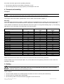
Construction and function of the linear feeder
Linear feeders are used for the actuation of conveying equipments. The actuation takes place by an electromagnet.
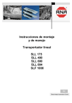
The following schematic diagram shows the function of a linear feeder:
B
C F
A
E
D
H
A
B
C
D
E
F
G
H
Conveying track and oscillating weight
Material to be conveyed
Spring assembly
Drive magnet
Armature
Counterweight
Shock absorber
Countermass
G
The linear feeder is a device of the familiy of vibratory bowl feeders. It is, however, equipped with a linear conveyor.
Electromagnetic vibrations are converted into mechanical vibrations and are used for conveying material B. If magnet
D, which is securely connected with the countermass F, is supplied with current, it generates a power that, dependent
on the vibration frequency of the mains supply, attracts and releases armature E. Within a period of the 50 Hz of the
A.C. network the magnet achieves its maximum power of attraction twice, as this is independent of the direction of
the current conduction. The vibration frequency therefore is 100 Hz. In case a half-wave is locked, it is 50 Hz. Please
take the vibration frequency of your linear feeder of the table "technical data" in chapter 1.
A linear feeder is a resonant system (spring-mass-system). The result is that the adjustment made at the factory will
rarely meet your requirements. Chapter 5 describes in detail how your linear feeder is adapted to your requirements.
Controlling of the linear feeder takes place by a low loss electronic control unit type ESG2000 or type ESG 1000. The
control unit of the linear feeder is separately delivered. At its front panel it is provided with a 7-pole plug-in connection, by which it is connected to the linear feeder.
The pin assignment of the socket is shown in the table "technical data" (chapter 1).
Notice
Detailed information on the complete range of control units may please be taken from the operating instructions for control units..
Rhein - Nadel Automation GmbH
VT-BA-SLL-SLF-GB
8
Stand 22.05.2012
All control units have got two main operating elements:
• By the mains switch the linear feeder is switched on or off.
• By the turning knob the conveying capacity of the transport unit is set.
4 Transport and mounting
Transport
Notice
Take care that the linear feeder cannot dash against other things during transport.
The weight of the linear feeder is please taken from the table "technical data" (chapter 1).
Mounting
The linear feeder should be mounted on a stable substructure (available as an accessory part) at the place where it is
used. The substructure must be dimensioned in a way that no vibrations of the linear feeder can be carried away.
Linear feeders are fastened to the shock absorbers from below (part G in the general drawing chap. 3). The following
table will give you a summary of the bore data of the various types:
Linear feeder type
SLL 175-175
SLL 175-250
SLL 400 - 400
SLL 400 - 600
SLL 400 - 800
SLL 400 - 1000
SLL 800 - 800
SLL 800 - 1000
SLL 800 - 1200
SLL 800 - 1400
SLL 800 - 1600
SLL 800 - 1800
SLL 800 - 2000
SLL 804 - 800
SLL 804 - 1000
SLL 804 - 1200
SLL 804 - 1400
SLL 804 - 1600
SLL 804 - 1800
SLL 804 - 2000
SLL 804 - 2400
SLL 804 - 2800
SLF 1000-1000
SLF 1000-1500
Tabelle: Bohrdaten
Length in mm
Width
in mm
Shock absorber
thread
125
175
200
300
450
500
300
450
600
750
900
1.050
1.200
300
450
600
750
900
1050
1200
1500
1800
370
870
37
37
60
60
60
60
83
83
83
83
83
83
83
87
87
87
87
87
87
87
87
87
130
130
M3
M3
M4
M4
M4
M4
M6
M6
M6
M6
M6
M6
M6
M8
M8
M8
M8
M8
M8
M8
M8
M8
M 10
M 10
Make sure that the linear feeder cannot come into contact with other devices during operation.
Further details on the control unit (bore plan, etc.) can be taken from the operating instructions of the control unit
separately delivered.
5 Starting
Notice
Ensure that the frame ( stand, base, frame etc.) is connected with the ground wire. (PE) If necessary,
predection earthing on spot should be provided.
Check, whether
• the linear feeder stands in an isolated position and does not come in securely with a solid body
• the linear track is screwed down and adjusted
• the connecting cable of the linear feeder is plugged in at the control unit.
Rhein - Nadel Automation GmbH
VT-BA-SLL-SLF-GB
9
Stand 22.05.2012
Attention
The electric connection of the linear feeder may only be made by trained personnel (electricians)! In
case modifications are made at the electric connection, it is absolutely necessary to observe the operating instructions "control units".
• The available supply voltage (frequency, voltage, output) is in accordance with the connection data of the control
unit (see type plate at the control unit).
Plug in the mains cable of the control unit and switch on the control unit by the mains switch.
Notice
At linear feeders which are delivered as a completely adjusted system, the optimal conveying capacity
is already set at the factory. It is marked on the scale of the turning knob with a red arrow. In this case
set the turning knob to the marking..
The optimal operative range of the linear feeder is at a controller position of 80% at the control unit. In case of higher
deviations (≥±15%) a readjustment should be carried out.
5.2 Adjustment
with spring assemblies for a conveying track weight, which is approx. 25 % lower than the maximum track
weight described in the Technical Data (chapt. 1), and a running speed of 4 - 6 m/min. In case heavier or lighter conveying tracks are installed or considerably faster or slower conveying speeds are required, the spring assemblies
must be modified. For that the following basic rules have to be observed:
Notice
At first a rough adjustment of the conveying speed (adjustment of the natural frequency) must be
made, which is followed by the adjustment of the running behaviour. Finally you adjust the conveying
speed (natural frequency).
5.2.1 Adjusting the required running speed
In case the required running speed is not achieved with the standard spring assembly, the current adjustment range
of the oscillating system must at first be found out, either natural frequency below 50 or 100 Hz or natural frequency above 50 or 100 Hz.
For that one or two plates are dismounted from the movable counterweight for a trial. If a change in the running
speed on the conveying track is recognized, it can be taken from the table below, whether springs must be installed or
removed. The controller position at the control unit may not be changed during this trial. In the factory the different
sizes are equipped.
Change of the running speed on
the conveying track after dismounting the counterweight
Required running speed is to
be increased
Required running speed is to
be reduced
Position of the natural frequency
Slower
1. Install counter weight
1. Install counter weight
2. Dismount springs
2. Dismount springs
> 50 or 100 Hz
1. Install counter weight
1. Install counter weight
2. Install springs
2. Dismount springs
Faster
Rhein - Nadel Automation GmbH
VT-BA-SLL-SLF-GB
10
< 50 or 100 Hz
Stand 22.05.2012
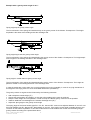
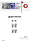
The following graphic chart shows the resonance curve of a linear feeder:
A
B
C
D
Conveying speed
Natural frequency
Resonance curve (not true to scale)
Spring power (number of springs)
Notice
The resonance curve of the linear feeder may not correspond to the mains frequency.
When exchanging the springs the valency of the various leaf spring sizes must be considered. As the spring size enters into the spring power in square, the following examples must be ovserved:
• 2.5 mm spring size = 6.25 spring power
• 3.0 mm spring size = 9.0 spring power
• 3.5 mm spring size = 12.25 spring power
A 3.5 mm leaf spring has about the same valency as two 2.5 mm leaf springs. For that reason it is recommendable to
carry out the final or fine adjustment always with thin leaf springs.
Notice
When changing the masses of counter and oscillating weights (installation or dismounting of counter or
additional weights) the running speed or the natural frequency of the linear feeder is changed. If necessary leaf springs must be added or removed.
Changing the spring assembly for linear feeders type SLL 175
Unscrew the 4 upper lateral spring fastening screws (“C”)(M4 DIN 912). The complete oscillator with mounted track
can now be lifted upwards.
Remove the desired spring pack by releasing the lower lateral spring fastening screws (“D”)(M4 DIN 912).
Before removing the spring pack, the protective conductor on the feeding side has to be taken out from the lower
spring fixture.
Screw the removed spring pack into the mounting device for fitting springs size 175 and fasten it in a vise. When installing and removing the laminated springs, make sure there are little distance plates between the springs.
If you do not have a mounting device for spring packs, proceed as follows:
Fix the dismounted spring pack horizontally in a parallel vise with smooth clamping jaws and perform the desired adjustments. When tightening the spring packs, make sure they are in parallel alignment.
The mounting device aligns the two spring fixtures to one another. The fastening screws of the springs are to be tightened with a torque of 3.5 Nm.
Reinstall the complete spring pack.
To restore the former alignment of the linear feeder, the adjusting bore on the upper counter mass end (“E”) has to be
aligned to the oscillator with a pin (4 mm in diameter with a minimum length of 45 mm).
Rhein - Nadel Automation GmbH
VT-BA-SLL-SLF-GB
11
Stand 22.05.2012
On the feeding side, the oscillator is aligned near the counterweight by inserting another pin (4 mm in diameter with a
minimum length of 45 mm) into the adjusting bore (“I”).
After having adjusted the spring angle to the desired position, the lateral fixing screws are tightened again with a
torque of 3.5 Nm.
Before putting into operation again, please remember to remove the centering pins.
Changing the spring assembly for linear feeders type SLL 400
Unscrew the 4 or 6 upper lateral spring fastening screws (“C”)(M6 DIN 912). The complete oscillator with mounted
track can now be lifted upwards. Remove the desired spring pack by releasing the lower lateral spring fastening
screws (“D”)(M6 DIN 912).
Before removing the spring pack, the protective conductor on the feeding side has to be taken out from the lower
spring fixture.
Screw the removed spring pack into the mounting device for fitting springs size 400 and fasten it in a vise. When installing and removing the laminated springs, make sure there are little distance plates between the springs.
If you do not have a mounting device for spring packs, proceed as follows:
Fix the dismounted spring pack horizontally in a parallel vise with smooth clamping jaws and perform the desired adjustments. When tightening the spring packs, make sure they are in parallel alignment.
The mounting device aligns the two spring fixtures to one another. The fastening screws of the springs are to be tightened with a torque of 12.5 Nm.
Reinstall the complete spring pack.
To restore the former alignment of the linear feeder, the adjusting bore on the upper counter mass end (“E”) has to be
aligned to the oscillator with a pin (6 mm in diameter with a minimum length of 70 mm).
On the feeding side, the oscillator is aligned near the counterweight by inserting another pin (6 mm in diameter with a
minimum length of 70 mm) into the adjusting bore (“I”).
After having adjusted the spring angle to the desired position, the lateral fixing screws are tightened again with a
torque of 12.5 Nm.
Before putting into operation again, please remember to remove the centering pins.
Changing the spring assembly for linear feeders type SLL 800 und SLL 804
Unscrew the lower armature fixing screw (“A”) (M6 DIN 912). Unscrew the 4 or 6 upper lateral spring fastening screws
(“C”)(M8 DIN 912). The complete oscillator with mounted track can now be lifted upwards.
Remove the desired spring pack by releasing the lower lateral spring fastening screws (“D”)(M8 DIN 912).
Before removing the spring pack, the protective conductor on the feeding side has to be taken out from the lower
spring fixture.
Screw the removed spring pack into the mounting device for fitting springs size 800 and fasten it in a vise. When installing and removing the laminated springs, make sure there are little distance plates between the springs.
If you do not have a mounting device for spring packs, proceed as follows:
Rhein - Nadel Automation GmbH
VT-BA-SLL-SLF-GB
12
Stand 22.05.2012
Fix the dismounted spring pack horizontally in a parallel vise with smooth clamping jaws and perform the desired adjustments. When tightening the spring packs, make sure they are in parallel alignment.
The mounting device aligns the two spring fixtures to one another. The fastening screws of the springs are to be tightened with a torque of 30 Nm.
Reinstall the complete spring pack.
To restore the former alignment of the linear feeder, the adjusting bore on the upper counter mass end (“E”) has to be
aligned to the oscillator with a pin (8 mm in diameter with a minimum length of 100 mm).
On the feeding side, the oscillator is aligned near the counterweight by inserting another pin (8 mm in diameter with a
minimum length of 100 mm) into the adjusting bore (“I”).
After having adjusted the spring angle to the desired position, the lateral fixing screws are tightened again with a
torque of 30 Nm.
Before putting into operation again, please remember to remove the centering pins.
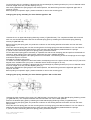
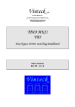
Changing the spring assembly for linear feeders type SLF 1000
C
A
5-25
░
C
.
.
G E D
..
H
D
I
F
Unscrew the 4 upper lateral spring fastening screws (“C”)(M12 DIN 912). The complete oscillator with mounted track
can now be lifted upwards.
Remove the desired spring pack by releasing the lower lateral spring fastening screws (“D”)(M12 DIN 912).
Before removing the spring pack, the protective conductor on the feeding side has to be taken out from the lower
spring fixture.
Screw the removed spring pack into the mounting device for fitting springs size 1000 and fasten it in a vise. When installing and removing the laminated springs, make sure there are little distance plates between the springs.
If you do not have a mounting device for spring packs, proceed as follows:
Fix the dismounted spring pack horizontally in a parallel vise with smooth clamping jaws and perform the desired adjustments. When tightening the spring packs, make sure they are in parallel alignment.
The mounting device aligns the two spring fixtures to one another. The fastening screws of the springs are to be tightened with a torque of 80 Nm.
Reinstall the complete spring pack.
To restore the former alignment of the linear feeder, the adjusting bore on the upper counter mass end (“E”) has to be
aligned to the oscillator with a pin (12 mm in diameter with a minimum length of 210 mm).
On the feeding side, the oscillator is aligned near the counterweight by inserting another pin (12 mm in diameter with
a minimum length of 210 mm) into the adjusting bore (“I”).
After having adjusted the spring angle to the desired position, the lateral fixing screws are tightened again with a
torque of 80 Nm.
Before putting into operation again, please remember to remove the centering pins.
Notice
If the base plate of the linear feeder is designed in a way that cross fastenings are only installed in the
area of the rubber-metal feet, the spring assemblies can be dismounted individually from below without
dismounting the vibrator.
5.2.2
Adjusting the required running behaviour or the sychronism of the linear feeder track
In order to achieve synchronism of the linear feeder track, the spring angle must be adjusted the same as the gravity
center angle. The gravity center angle is determined by the position of the two gravity centers of oscillating and counterweight.
Rhein - Nadel Automation GmbH
VT-BA-SLL-SLF-GB
13
Stand 22.05.2012
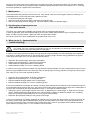
Example with a gravity center angle of 12.5 °
1 2,
5░
12
,5
░
Spring angle equals gravity center angle
The force direction of the springs is initiated exactly on the gravity center of the vibrator. Consequence: The height
amplitude is the same at the feeding and at the discharge side..
12 ,5
░
20
░
Spring angle larger than the gravity center angle
The force direction of the springs is initiated before the gravity center of the vibrator. Consequence: The height amplitude is higher in the feeding area than in the discharge area.
12,
5░
5░
Spring angle is smaller than the gravity center angle
The force direction of the springs is initiated behind the gravity center of the vibrator. Consequence: The height amplitude is smaller in the feeding area than in the discharge area.
In case the angles are not the same, the conveying tracks are running unsteadily. In case of very high deviations of
this angle the conveying track can even show lateral deflections (oscillations).
The gravity centers or angles can be influenced by the following measures:
•
•
•
•
•
Add or displace counterweight ("F")
Choose the track position and height in a way that a favourable gravity center is achieved
Keep the track weight as low as possible, in order to keep the vibrator gravity center as low as possible.
Install an additional counterweight in the vibrator discharge area ("G").
Adjust the spring angle to the gravity center angle
The spring angle of the linear feeders type SLL 175, SLL 400 and SLF 1000 can be adjusted between 5° and 25° or at
the linear feeders type SLL 800 and SLL 804 between 5° and 20°. If the gravity center angle is outside this area, synchronism of this track is impossible. In this case modifications must be made at the counter and oscillating weight
gravity centers according to the points listed above.
Rhein - Nadel Automation GmbH
VT-BA-SLL-SLF-GB
14
Stand 22.05.2012
Spring angle adjustment
Fix the vibrator towards the counter mass (see chapt. 5.2 "Changing the spring assemblies at the individual linear
feeders"). After that the four lateral spring fastenings ("C" + "D") can be loosened, in order to swing the spring assembly into the desired spring angle. After that fasten the spring fastening screws with the permissible tightening torque
(see "Technical Data", chapt. 1) and remove the adjusting screws, distance plates or bolts.
Adjustment of the magnet air gap
The air gap between armature and magnet adjusted in the factory can be taken from the "Technical Data" (chapt. 1)
The adjustment of the air gap can be made from the outside without dismounting any component parts. Slightly
loosen both armature fastening screws ("A" or "A" + "B") (M4 DIN 912 at linear feeder type SLL 175; M5 DIN 912 at
linear feeder type SLL 400: M6 DIN 912 at linear feeder type SLL 800 and SLL 804; M6 DIN 912 at linear feeder type
SLF 1000 at the right and left side). In both bore holes in the oscillating profile ("H") a round pin (φ 1mm, 80 mm long
at SLL 400; φ 3 mm; 80 mm long at SLL 800 and SLL 804; φ 2.5 mm, 250 mm long at SLF 1000) must be sticked
through. By pressing both armature fastening screws against running direction and subsequent tightening the specified magnetic gap is adjusted (see "Technical Data" chapt. 1) (at the linear feeder type SLF 1000 at both magnets).
After that pull out the round pins. In case there are no round pins, the magnetic gap can be adjusted from below (perhaps after dismounting the complete linear feeder from the supporting structure or from the supporting table) by
means of a feeler gauge or distance pieces according to the prescribed magnetic gap.
Notice
At a turning knob position of 100% at the control unit and a correctly adjusted magnetic gap the magnet may not dash against the armature. In case this happens, proceed according to point 5.2 (remove
springs).
The aim of the adjustment is:
If the required conveying speed is achieved at a controller position of 80 %, the conveying speed must always increase when a weight plate is removed.
Notice
Take care that the number of springs per spring assembly does not differ by more than 2-3 springs
6 Specifications for the design of the
track
As the vibrator is sufficiently flexible owing to the use of aluminim profile, the conveying tracks should be of a very
light design. Only in case of conveying tracks projecting over the vibrator (in the feeding area max. 100 mm, in the
discharge area max. 200 mm) the design of the conveying track must be correspondingly inflexible to distortion. In
order to achieve an additional, lateral distortion-inflexibility, a one-piece supporting plate of 4 - 6 mm thick aluminium
should be screwed on the linear feeder profiles. by replacing
the linear feeder profiles you get the small "S" or broad "B" construction type.
The higher the feeding speed is, the larger must the clearance between upper edge of the part to be conveyed and
the lower edge of the cover of the conveying track be chosen. If possible the clearance must be brought to the largest
permissible measure. When installing and fastening the conveying tracks the following points must be observed:
•
•
•
•
Install closely to the upper edge of the vibrator
If possible put it on the center of the aluminium profile
Choose solid, rigid screwings (minimum M5)
In order to achieve a higher conveying speed the linear feeder can be installed with a slight inclination of approx.
3-5°.
• Under no circumstances use loose or hinged, unscrewed covers.
The conveying track may also consist of several short sections, which are assembled and scrwed down on the vibrator. At the feeding side flat chamfers facilitate passing of the workpiece from one to the other conveying track section.
The construction consisting of several sections is especially recommended for the use of hardened or surfacehardened conveying tracks (low distortion manufacture)
Rhein - Nadel Automation GmbH
VT-BA-SLL-SLF-GB
15
Stand 22.05.2012
Very light conveying tracks can be realized by using aluminium-rails or aluminium profiles. The necessary abrasion
resistance can be achieved by segments made of hardened spring band steel, which are screwed in or on. This segments are available on request at the manufacturer.
7 Maintenance
The linear feeders are generally maintenance-free. They should, however, be thoroughly cleaned in case they are
considerably dirty or after fluids have been spilled over them.
• For that first unplug the mains plug.
• Clean the inside of the linear feeder, especially the magnetic gap.
• After the mains plug has been plugged in, the linear feeder is ready for operation again.
8 Stockkeeping of spare parts and
after-sales service
The range of the spare parts available may be taken from the separate spare parts list.
In order to guarantee quick and faultless handling of the order, please always state the type of equipment (see type
plate), number of pieces needed, spare part name and spare part number.
You will find a list of our service addresses on the back page of the cover.
9 What to do, if... (Instructions for
trouble-shooting)
Attention
The control unit or the connecting terminal box may only be opened by an electrician. Before opening
the a.m. devices, the mains plug must be unplugged!
In case the conveying track has no steady running speed or height amplitude, but at the discharge side a higher running speed or height amplitude than on the feeding side, the spring angle has been wrongly adusted to the gravity
center angle (see chapt. 5.2.2.) In this case proceed as follows:
•
•
•
•
Adjust the spring angle larger at all spring assemblies
Displace the counterweight "F" against running direction
Install additional weight plates at the counterweight
Install additional weight "G" into the oscillating profile
In case the conveying track has no steady running speed or height amplitude, but at the feeding side a higher running
speed or height amplitude than at the discharge side, the spring angle is wrongly adjusted to the gravity center angle
(see chapt. 5.2.2) In this case proceed as follows:
•
•
•
•
Adjust the spring angle smaller at all spring assemblies
Displace the counterweight "F" in running direction
Dismount additional weight plates at the counterweight
Dismount additional weight "G" from the oscillating profile
If the running behaviour is unsteady at a steady conveying track speed and if the material to be transported jumps too
much between bearing surface and cover, the gravity center angle and the adjusted spring angle of the total system is
too large and consequently the height amplitude too high. In this case proceed as follows:
• Change the gravity center angle (make it more "flat"), by displacing the counterweight "F" against the running direction, installing additional weight plates at the counter weight, installing an additional weight in the oscillating
profile and choosing a lighter design for the conveying track if necessary.
• Adjust the spring angle according to the gravity center angle.
If the running behaviour is unsteady especially at material to be conveyed with large surface or which is fouled by oil,
the gravity center angle and the adjusted spring angle of the total system is too small. The height amplitude is too
low. Owing to that the motion of projection cannot take place and in case of oily workpieces the adhesive power is
higher than the projectile power, i. e. the workpiece cannot be lifted.
Rhein - Nadel Automation GmbH
VT-BA-SLL-SLF-GB
16
Stand 22.05.2012
In this case proceed as follows:
• Change the center of gravity angle (make it "steeper"), by displacing the counterweight "F" in running direction,
dismounting additional weight plates at the counter weight, dismounting the additional weight from the oscillating
profile.
• Adjust the spring angle according to the new gravity center angle
In case the conveying track cannot be adjusted according to the above mentioned criteria, and, if eg. lateral vibrations or in certain areas "dead points" occur, the track stiffness is insufficient. The points of impact or separation work
towards each other or asymmetrical structural parts of the track lead to unsteady running behaviour. In this case proceed as follows:
• Mount additional stiffening ribs
• Connect impact or separation points by screwings
• Provide asymmetrical structural parts with counterweights or replace them by lighter materials.
Trouble
Linear feeder does not
start when being
switched on
Possible cause
Mains switch off
Remedy
Switch on the mains switch
Mains plug of the control unit is not
plugged in
Plug in the mains plug.
Plug in the 5-pole plug at the control unit
Connecting cable between linear feeder
and control unit is not plugged in
Linear feeder vibrates
slightly
Fuse in the control unit defective
Turning knob at the control unit is set to
0%
Replace the fuse
Set the controller to 80%.
Remove the transport securing device.
Transport securing device has not been
removed
Wrong vibration frequency
Check, whether the code in the plug of the
linear feeder is correct (see type plate and
"technical data" (chap. 1)
Attention:
in case a linear feeder SLL 400 is operated
without a bridge in a 7-pole plug, the control unit and the magnet is in danger!
After a longer operating Fastening screws of the linear track have
Retighten the screws.
time the linear feeder
worked loose
does no longer come
Tighten the screws (tightening torques see
up to the conveying
Screws at one or two spring assemblies
"technical data" (chapt. 1)
capacity required
have worked loose
Readjust the magnetic gap (gap width see
Magnetic gap misadjusted
"Technical Data" (chapt. 1)
Linear feeder produces
loud noise
Vibrator displaced towards the countermass
Readjust the vibrator (see chapt. 5.2.1)
Foreign bodies in the magnetic gap
Switch off the linear feeder and remove
the foreign bodies, after that check the
magnetic gap adjustment
Readjust the linear feeder. Springs must
be removed. See chapt. 5, adjustments
Linear feeder cannot be The spring constant of the oscillating sysadjusted to a constant
tem has changed. The linear feeder works
conveying speed
close to the resonance point
Rhein - Nadel Automation GmbH
VT-BA-SLL-SLF-GB
17
Stand 22.05.2012
®
Rhein-Nadel Automation GmbH
Reichsweg 19/23 Ÿ D - 52068 Aachen
Tel (+49) 0241/5109-159 Ÿ Fax +(49) 0241/5109-219
Internet www.rna.de Ÿ Email [email protected]
Rhein-Nadel Automation GmbH
Zweigbetrieb Lüdenscheid
Nottebohmstraße 57 Ÿ D - 58511 Lüdenscheid
Tel (+49) 02351/41744 Ÿ Fax (+49) 02351/45582
Email [email protected]
Rhein-Nadel Automation GmbH
Zweigbetrieb Ergolding
Ahornstraße 122 Ÿ D - 84030 Ergolding
Tel (+49) 0871/72812 Ÿ Fax (+49) 0871/77131
Email [email protected]
HSH Handling Systems AG
Wangenstr. 96 Ÿ CH - 3360 Herzogenbuchsee
Tel +(41) 062/95610-00 Ÿ Fax (+41) 062/95610-10
Internet www.rna.de Ÿ Email [email protected]
RNA AUTOMATION LTD
Hayward Industrial Park
Tameside Drive, Castle Bromwich
GB - Birmingham, B 35 7 AG
Tel (+44) 0121/749-2566 Ÿ Fax (+44) 0121/749-6217
Internet www.rna-uk.com Ÿ Email [email protected]
Vibrant S.A.
Pol. Ind. Famades C/Energia Parc 27
E - 08940 Cornella Llobregat (Barcelona)
Tel (+34) 093/377-7300 Ÿ Fax (+34) 093/377-6752
Internet www.vibrant-rna.com Ÿ Email [email protected]
Rhein - Nadel Automation GmbH
VT-BA-SLL-SLF-GB
18
Stand 22.05.2012