1
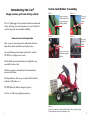
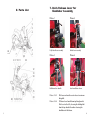
“Dedication to Excellence”
“Dedication to Excellence”
Single Seater Golf Buggy
Owners Manual
www.i-motioncaddys.com
[email protected]
www.i-motioncaddys.com
[email protected]
Introducing the i-m4
Single seater golf and utility vehicle
The i-m4 golf buggy is like any other electrical or mechanical
device. Cleaning, care and inspection is a "must" which will
result in longer life and extended reliability!
General care and inspection
Score Card
Holder Instructions
Assembly
Assembly
Picture 1
Picture 2
Mount score card
holder bracket into
Picture 1.
on back
of
Insert the handles onsleeve
the bottom
bracket
into the head of bolt.
golf bag holder.
Fix using
bakelite
knob.
Picture 2.
Insert the upper bracket into the rectangular handle.
Picture
Picture
3
3.
Picture 4
Insert the bracket bolt and tighten.
After every use clean any mud or debris from under the
body either with a hand brush or a light air hose.
Picture 4.
Use a mild detergent and warm water for the exterior.
DO NOT use a high-pressure wash.
Picture 5.
Check all bolt and nut connections are tight before use,
especially the wheel nuts.
Picture 6.
Fix using
bakelite
knob.
Fix the scorecard holder to bracket.
Press on score card
holder to supprting
bracket.
Insert the scorecard holder
and tighten the buckle.
Finished assembly.
Check tyre pressure and maintain the recommended
pressure at all times.
Recharge batteries after every use and check the battery
indicator is full before use.
DO NOT allow the battery charger to get wet.
Let the i-m4 add to your golfing experience.
Picture 1.
To access the batteries, release clamp at the rear of the buggy, lift the
1
Picture 1.
and
the release
bonnet bakelite
arm. knob at the rear of the buggy,
Tobody
access
theattach
batteries,
lift the body and attach the fixed hold up arm.
10
Golf bag
Bag holder
Holder and
Assembly
Golf
Scorecard holder
1. Safety Operation
Picture 2
Picture 1
Picture 1
Picture 2
1.1. Safety
Please read
Please
read the
the following
following instructions
instructions carefully
carefully before
before using
using the
the i-m4
i-m4 golf
golf
buggy.
buggy.
Head of bolt
PictureHole
1 on bottom
bracket
Locate pivot arm into slot provided
on fixing angle. Attach to i-m4
and semi-fasten
Picture 3 bakelite knob
provided.
Upper bracket
Rectangular hole
Picture
2
locate bottom pivot arm into fixing
hole provided and semi-tighten
bakelite
knob
Picture
4 provided.
Picture 3
Picture 3
Tighten both top and bottom
bakelite knobs for firm fix.
Reverse process to remove.
Bolt on bottom
bracket
Bolt on upper
bracket
Scorecard
Bracket for
scorecard
throttle
handle as
support
golfthe
buggy
is designed
toacarry
onewhen mounting the
·· DO
TheNOT
i-m4use
buggy.
person.
· Turn off ignition when not in use.
·
The buggy is NOT road legal.
· Leave buggy in neutral mode when not in use.
·
Please use the throttle to decrease the speed
· The
i-m4
golf buggy
is designed to carry one person.
when
turning
the buggy.
The
buggy
NOT
road legal.
Please
useisthe
throttle
to increase the speed
when use
climbing
a hill. to decrease the speed when turning the
Please
the throttle
buggy.
·
When driving the buggy take care in crowded
· Please
increase
thetight
speed
when climbing a hill.
areas,use
wetthe
or throttle
slipperyto
surfaces
and
gaps.
··
·
driving
buggy
takethe
care
in4 crowded
buggy areas, wet or
·· When
Do not
allowthe
others
to use
i-m
slippery
surfaces
and
tight
gaps.
without your permission.
· Do not allow others to use the i-m44buggy without your
·
Please do not stand up on the i-m buggy when
permission.
in motion as you may lose your balance.
· Please do not stand up on the i-m4 buggy when in motion
as you
· may
Please
notbalance.
lean side from side to side on the im4.
losedo
your
4 down hills backwards.
·· Please
Do notdodrive
the i-m
not lean
side
from side to side on the im4.
Picture 5
Picture 6
· Do
Trynot
to avoid
pot i-m4
holesdown
or uneven
paths.
drive the
hills backwards.
4 buggy
to avoid
pot
holes or
paths.
in uneven
a dry area
or under cover
· Try
Keep
the i-m
when
not
in
use.
· Keep the i-m4 buggy in a dry area or under cover when not in use.
Scorecard
bracket
9
Golf bag
holder
Bakelite
bolt
Finished Assembly
· Do
Donot
notuse
usea amobile
mobilephone
phonewhen
whendriving
drivingthe
thebuggy.
buggy.
· Do not get off the buggy until it has come to a complete stand still.
·
Do not get off the buggy until it has come to a
· The direction switch should not be changed when the buggy is
complete stand still.
moving.
·· The
TheSpeed
direction
switch
should
notchanged
be changed
when
switch
should
not be
when
the buggy is
the
buggy
is
moving.
moving.
2
7.Quick Release Lever for
7. Handlebar Assembly
Handlebar Assembly
2. Parts List
1
2
Picture 1
Picture 1
Picture 2
Picture 2
Handlebar
operation
Fully
locked lever
assembly
Bolt
Unlock lever assembly
Picture
Picture 33
Picture 44
3
4
5
24
7
8
9 10 11
6
22
23
12
13
14
Clip
Finished head
Fold down lever handle
15
20
19 18 17 16
21
Lever handle bar release
Picture 1 & 2 Insert the handlebar into the hole and lock the bolt
with Flick
a spanner.
Picture 1 & 2
lever on handle over to release tension on
Picture 3
bolt. and clip tightly using clamp.
Lock fixing
in position
Picture
Pull down
lever handle from top fixing bracket.
Picture
4 3 & 4
Finished
assembly.
Slide lever to the left, releasing the holding bolt
from the top bracket therefore releasing the
handlebars to fold down.
3
8
5. Inspection
Inspection and
and maintenance
maintenance
5.
Parts
Parts Inspection
Inspection
Golf buggy Golf buggy
After use clean any mud or debris from under
After use clean any mud or debris from under
the the
body
either with a hand brush or a light body either with a hand brush or a light air
air hose.
Onlyuse
usea amild
mild
detergent
warm
hose. Only
detergent
withwith
warm
water
for for
thethe
exterior.
high- water
exterior.DO
DONOT
NOT use aa highpressure
wash.
pressure
jet jet
wash.
Steering
system Steering system
Ensure
all all
parts
are
Ensure
parts
arefunctioning
functioning properly.
properly.
Accelerator
throttlehandle
handle Accelerator throttle
Ensure
thethe
buggy
moves
throttleisis
Ensure
buggy
moveswhen
when the
the throttle
turned
anti-clockwise
it stops
the turned
clockwise andand
it stops
whenwhen
the throttle
is released.
throttle
is released.
Battery
powerindicator
indicator Battery power
Ensure
thethe
power
Ensure
powerhas
hasenough
enough charge
charge
remaining
beforeuse.
use.
remaining
before
Seat
Seat Ensure
thethe
seat
is isfixed
Ensure
seat
fixedproperly.
properly.
Brake
pedal Brake pedal
Ensure
thethe
brake
Ensure
brakepedal
pedalworks
works freely.
freely.
Tyres Ensure the tyres are in good condition and that
Tyres
Ensure the tyres are in good condition and that
theythey
areare
at the
recommended
airpressure
pressure
at all
at the
recommended air
at all
times.
times.
Wheels
Wheels Check
all all
nuts
and
thewheel
wheel
Check
nuts
andbolts
boltsand
and ensure
ensure the
nutsnuts
areare
tight
and
tight
andsecure.
secure.
Batteries
Batteries
Recharge
batteries after every use and check
Recharge batteries after every use and check
the the
battery
indicator
use.
battery
indicatorisisfull
fullbefore
before use.
Battery
charger Battery charger
DO DO
NOT
allow the battery charger to get wet.
NOT allow the battery charger to get wet.
6. Trouble shooting
The buggy won’t start · Check the key is in the on position.
The buggy won't start
· Check
the the
batteries
are
connected
properly.
· Check
key is in
the
on position.
· Ensure
thethe
footbrake
NOT
engaged.
· Check
batteriesisare
connected
properly.
Battery indicator will not reset
after 8 hour charge · Press
the “Reset
indicator
This ismode.
situated
· Ensure
the buggy
is notbutton”
in free wheel
under the body on the white controller cover
Other
Other
· Contact your supplier
· Contact
your supplier
· Check charger is working
6. Trouble shooting
· Check the battery power indicator.
7
· Ensure
thethe
buggy
is NOT
free wheel mode.
· Check
battery
powerinindicator.
2.1 Parts list
1)
1)
Controlpanel
panel
Control
2)
2)
3) 3)
Golfbag
bagholder
holder
Golf
Handlebarrelease
releasepin
pin
Handlebar
4)
4)
5)
5)
6)
6)
7)
7)
8)
8)
9)
Body
Body
Front suspension
Front suspension
Front bumper
Front bumper
Foot brake pedal
Foot brake pedal
Horn button
Horn
button
Battery
power indicator
9)
power
indicator
10) Battery
Direction
switch
10)
switch
11) Direction
Accelerator
throttle
11)
12) Accelerator
Ignition throttle
13) Ignition
Seat suspension
12)
14) Seat
Rearsuspension
carry bracket
13)
15) Rear
Electromagnetic
14)
carry bracketbrake handle (Free wheel lever)
16) Rear tyre
15) Electromagnetic brake handle
17) Padded seat
16) Rear tyre
18) Seat body assembly
17) Padded seat
19) Footplate
18) Seat body
20) Front tyre
19)
21) Footplate
Bonnet release catch
20)
22) Front
Microtyre
switch
21)
release
catch
23) Bonnet
High/low
speed
switch
24)
Slide cap battery charger point
4
3. Operation
3.1 Operation
·
·
·
·
·
·
·
·
·
Please remove the charge
chargerfrom
fromthe
thebuggy
buggybefore
beforeturning
turningthe
theignition
ignition
key on.
Turn ignition key on.
Ensure charge indicator is sufficient.
Press FWD to move forward.
Press REV to move in reverse.
Turn throttle clockwise
to increase
speed.
anti-clockwise
to increase
speed.
Release throttle to slow down or stop.
Brake pedal is for emergency stop only.
When the throttle is released the back wheel is locked automatically
automatically
for parking
parking on
on inclines
inclinesor
ordeclines.
declines.
Motor brake
Motor
brake handle
handle
·· ·· ·
The electro
magnetic
brake lever
(free
wheel
lever)
be attached
found
The
red motor
brake handle
can be
found
under
thecan
body
under
the body attached to the motor.
to
the motor.
Make sure
magnetic
brake
leverposition
is in thetovertical
position
Make
sure the
the electro
red handle
is in the
vertical
engage
the
to engage the motor.
motor.
electro
magnetic
to free
wheel the vehicle.
Dis-engage the red
motor
handlebrake
to freelever
wheel
the vehicle.
Battery discharging
Battery
discharging Point
Point
·· ·· The battery
charger socket
socket is
is located
located under
under the
the seat.
seat.
The
battery charger
Ensure the
the cover
Ensure
cover is
is replaced
replaced after
after charging.
charging.
Power display
Power
display
·
·
·
·
·
·
Running time will change according to ground conditions and terrain.
Running time will change according to ground conditions and terrain.
FULL CHARGE: LED light/bar is at the top
FULL CHARGE: All the LED lights are on.
MINIMAL CHARGE: LED light/bar is at the bottom
MINIMAL CHARGE: One LED light is on.
4. Specifications
Item
Item
Parameter
Parameter
Motor 36V1200
1200Watt
Wattpermanent
permanentmagnetism
magnetism
36V
Battery 12V48AH
48AHx x33/ 12V 45AH x 3 / 12V 75AH x 3
12V
Controller Curtiscontroller
controller1227-3402
1227-3402dc36v
dc36v//160A
160A
Curtis
Accelerate Hallaccelerator
acceleratorcontinuous
continuousvariable
variablespeed
speedsystem
system
Hall
Charger Fullautomatic
automaticefficiency
efficiencypulse
pulsecharger
charger5 Amp or 8 Amp
Full
Dimension 1.27x x0.82
0.82x x1.05m
1.05m
1.27
batteries)
Weight (without
(without
batteries) 105kg
105kg
Carrying capacity 200kg
200kg
Maximum speed 13-15km/h
13-15km/h
Slopespeed
climbing
capacity
Low
17 degrees
4-6km/h
Brake climbing
range capacity Slope
< degrees
4m 3 secs
17
Turningrange
radius
Brake
3m3 secs
<<4m
Brake method
Turning
radius & mechanical brake
<Electromagnetic
3m
Micro switch
Brake
method Motor protectiory.
Power cut off
switch
Electromagnetic
& mechanical
brake
Wheelswitch
base Micro
90cmprotectiory. Power cut off switch
Motor
Minimalbase
ground
clearance
Wheel
11cm
90cm
Tyre
Minimal
ground clearance 32.5cm x 15cm 4 Wheels
11cm
pressure
Tyre Front 18
psi and
Rear 20 psi
32.5cm
x 15cm
4 Wheels
Tyre pressure Front 20 psi and Rear 20 psi
Seat
Seat
· The seat height can be adjusted to 3 positions using the bolts at
·
·
The
seatend
height
cansuspension
be adjusted
to 3 positions using the bolts at the
the top
of the
spring.
top
the asuspension
spring.
Seatend
canofhave
quick-release
system fitted to allow easier seat removal.
Golf bag holder
·· The
golf bag
bag holder
holder is
is attached
attached and
and detached
detached using
using the
the lower
lower and
The golf
and
upper
the front
of front
the buggy.
upper clamps
bakeliteatknobs
at the
of the buggy.
Rear fold down carrier
carrier
·
·· 5
To open: Release the bakelite bolt, fold down the rear bracket and
tighten the bakelite bolt.
To
close: Release
Release the
bakelite bolt,
the rear
rear bracket
bracket and
and
To close:
the bakelite
bolt, push
push up
up the
re-tighten
re-tighten the
the bakelite
bakelite bolt.
bolt.
i-m4 Available accessories
•
•
•
•
•
•
•
•
•
•
•
•
Mud guards - Front and rear Mud basket
guards - Front and rear
Rear
Front basket assembly
Fold
up golfcover
bag holder
Waterproof
Umbrella
Scorecard holder
holder
Sun shade
canopy
Back
seat rest
Front
head
lights
Strobe lights
Front and rear indicator
Quick release seat system
• Rear golf bag holding bracket
Rear basket
basket assembly •• Front
• Fold up golf bag holder
•• Waterproof
cover Umbrella holder
•• Scorecard
Back seatholder
rest Strobe
lights
•• Sun
shade
canopy Fronthead
and lights
rear indicator
•• Front
• Ramps
6