1
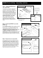
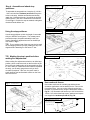
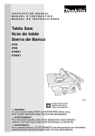
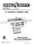
Owner’s Manual
Please read this Owner’s
Manual before use and keep it at
hand for reference.
From simple routing operations
such as edge forming, grooving,
dadoing, or rabbeting, to high
quality joinery, your new INCRA
Fence System and Right Angle
Fixture combined with the INCRA
Jig Positioner will provide an
unlimited source of precision and
satisfaction for all your router table
projects. The T-slot design of the
Fence and Right Angle Fixture
permit the easy addition of user
made sub fences and auxiliary
faceplates for specialty
applications. Durable aluminum
construction and double laminated
Fence and Stop ensure reliable
performance for years to come.
SAFETY
Important safety instructions for using the INCRA Fence System
•
Before using the INCRA Fence System and Right
Angle Fixture, carefully read and follow all of the
instructions and safety information in this manual.
•
Always turn off the power and make sure that the bit or
blade is fully stationary before moving any component
of the INCRA Fence System to any new setting.
•
•
•
Use appropriate safety devices. Keep hands clear of
the bit or blade. Always use a push stick, rubber soled
push block, or other safety devices to keep your hands
safely away from the cutting tool.
•
Never let the bit or blade come in contact with the
aluminum body of the INCRA Right Angle Fixture.
When using the INCRA Fence System and Right Angle •
Fixture with any other tools, make sure that all safety
guards and other safety equipment supplied by the
manufacturer of that tool are securely in place and
functional
•
Never let any part of the INCRA Fence System or Right
Angle Fixture interfere with another tool’s safety guards
or other safety equipment.
•
Never attempt to hold your work to the INCRA Right
Angle Fixture using your hands alone. Always use a
clamp or other suitable holding device to securely hold
your work to the front face of the fixture.
Never let the bit or blade come in contact with the
wooden runners on your INCRA Right Angle Fixture.
Always clamp a wooden stop to the outfeed end of the
fence to stop the forward motion of the Right Angle
Fixture before the bit contacts the wooden runners.
Made in America by:
www.incra.com
Taylor Design Group, Inc.
PO Box 810262
Dallas, TX 75381
Phone: 972-242-9975
INCRA Products are protected by the following US Patents: #4,793,604, #4,930,221, #5,195,730, #5,725,074, #5,423,360, #5,716,045, #6,237,457, #6,557,601, #6,672,190
Other patents granted or pending.
© 2005 by Taylor Design Group, Inc.
Printed in the U.S.A.
INCRA is a registered trademark of Taylor Design Group, Inc.
1
INCRA Fence & Stop - Assembly and Use
Step 1. Attach the INCRA Jig to
your router table.
The INCRA Fence System is designed to
work as the “front end” to the INCRA Jig
Positioner, so the first step is to attach your
INCRA Jig to your router table. After
following the instructions in the INCRA Jig
owner’s manual for attaching your INCRA
Jig to a wooden base panel, use C-clamps
to attach the base panel to your router
table as shown in Fig. 1. If your router
table is “INCRA-ready” with built-in
mounting slots, you can use the bolt,
washer and knob combination shown in
Fig. 1A for maximum versatility and ease
of use.
Fig. 1
Attach wooden base panel
… or, if your router table is
“INCRA-ready” with built-in
mounting slots, you can attach
the base panel with bolts,
washers and knobs for greater
ease of use
Base panel
Router table
Fig. 1A
Use C-clamps to attach a 3/4” thick by
9” wide plywood or MDF base panel to
your router table …
Step 2. Attach the INCRA Fence to the
INCRA Jig
Fig. 2
Attach fence to the INCRA Jig
1/4-20 x 1 1/4”
socket head cap
screw and washer
(2)
Open hardware pack D-03. Place a washer on each of
the (2) 1/4-20 x 1 1/4” socket head fasteners and
1/4-20 rectangular
insert through the upper holes on the fence. Now
nut (2). Raised rim
loosely thread on the 1/4-20 rectangular nuts.
MUST face AWAY from
CAUTION: The raised rim on the two rectangular
the fence
nuts MUST FACE AWAY from the fence, as
shown in Fig. 2. Lower the rectangular nuts into the Tslots located on the front end of the INCRA Jig, then
tighten the fasteners using the included 3/16” hex key.
Step 3. Square fence to router table.
Fig. 3
After attaching your fence to the INCRA Jig, check
for squareness with your router table top. If any
adjustment is necessary, loosen the fence mounting
screws and insert a paper or plastic shim between
the INCRA Jig and the rear face of the fence, Fig. 3.
A shim placed below the fasteners will increase the
angle between the fence and the table. A shim
placed above the fasteners will decrease the angle.
Tighten the fasteners to secure the fence.
Square Fence to the router table
Place shim between top of jig and
fence to decrease angle
Place shim between bottom of jig
and fence to increase angle
2
Square
Step 4. Assemble and attach stop
positioner.
Fig. 4
To assemble the stop positioner, insert the (2) 1/4-20 x
1 3/4” hex bolts from hardware pack D-03 through the
holes on the stop. Add the two washers and loosely
attach the 1/4-20 thumb knobs. Now slide the hex bolt
heads into the T-slot on the outfeed end of the INCRA
Fence, Fig. 4. Position the stop as needed, and tighten
the thumb knobs before use.
Attach stop positioner
1/4” flat washer (2)
1/4-20 thumb knob (2)
1/4-20 x 1 3/4” hex
bolt (2)
Stop positioner
Using the stop positioner.
Fig. 5
Using the stop positioner
Fig. 6
Mark stop position
Use the stop positioner to limit the length of cuts made
with your INCRA Fence System. The cutaway notch
permits the stop to be positioned safely inside your
cutter’s diameter for applications such as dovetail pin
cuts shown in Fig 5.
TIP: The un-notched end of the stop can also be used
for the stopping surface by simply rotating the stop 180
degrees before attaching it to the fence’s T-slot.
TIP: Marking the stop’s position before
making fine adjustments.
When making fine adjustments relative to an initial stop
position, place a reference mark on the front face of the
fence along the leading edge of the stop positioner, Fig
6. Now, when you loosen the thumb knobs to reposition
the stop, you an easily gauge how much you have
moved the positioner. After use, the pencil mark is
easily wiped off the hard laminate surface on the front
face of the fence.
Fig. 7
User made sub fences.
User made sub fences
User made sub fences for variable gap width and zero
clearance applications can be attached to the T-slot on the
front of the fence. Just cut to size, drill and counter bore
the MDF or plywood fences, using the dimensions shown in
Fig 7A. You can attach sub fences up to 3/4” thick with the
1/4-20 x 3/4” socket head cap screws, washers and square
nuts supplied in hardware pack D-04, Fig. 7A.
Fig. 7A
Sub fence dimensions
5”
5/16” diameter through hole
with 5/8” diameter by 3/8”
deep counter bore (2)
1/4-20 x 3/4” socket head screw (4)
6”
2”
3/4”
1/4” washer (4)
1/4-20 square nut (4)
3
10”
INCRA Right Angle Fixture - Assembly and Use
Step 1. Attach faceplate to base.
Fig. 8
Assemble Right Angle Fixture
Attach the INCRA Right Angle Fixture faceplate to the
INCRA Right Angle Fixture base using the (4) supplied
10-32 x 5 1/2” hex bolts and rectangular
nuts. Insert the bolts through the four
Fig. 8A Faceplate alignment
holes in the base and loosely attach the
(4) rectangular nuts. Now slide the T-slots
on the back of the faceplate over the
rectangular nuts, Fig. 8. Make sure the
two surfaces marked with an “x” in Fig. 8A
x
are aligned flush, then securely tighten the
x
hex bolts.
10-32 x 5 1/2” hex bolts (4)
Right angle fixture base
Right angle fixture faceplate
10-32 rectangular nuts (4)
See detail in Fig. 8A
Align surfaces marked “x”
Step 2. Attach wooden runners.
Fig. 9
Attach the two wooden runners to the bottom of your
Right Angle Fixture base using the (4) 10-32 x 1 1/4”
Phillips screws, washers and hex nuts as shown in
Fig 9. Each runner should extend about 1/2” beyond
the rear of the base.
Attach wooden runners
Wooden runner (2)
10-32 hex nut (4)
#10 washer (4)
10-32 x 1 1/4”
Phillips screw (4)
T-slot on bottom of Right
Angle Fixture (4)
Right Angle Fixture operation.
Before clamping a work piece to your Right Angle Fixture,
always press the fixture against your fence, then
immobilize by clamping it to the table with a spring clamp,
Fig. 10. When positioning the work piece against the
faceplate, make sure that the edges of the boards are
against the fence and the ends are contacting the table
surface, then clamp in place using a wooden handscrew
clamp.
Fig. 10
Using the Right Angle Fixture
CAUTION: Do not allow any part of your
hands to hang below the aluminum body of
the Right Angle Fixture. Always keep hands
well away from the bit.
To avoid contacting the wooden runners with the router bit,
clamp a wooden stop block to the outfeed end of the fence
to stop the forward travel before contact, Fig. 11.
Fig. 11
Third: Position stock against fence and
clamp with a wooden jaw clamp
Avoid contacting wooden runners
Second: Immobilize with spring
clamp (acts like a “third hand”)
Avoid making contact between the
wooden runners and the router bit by
clamping a wooden stop block to the
outfeed side of the fence to stop the
forward travel of the Right Angle
Fixture
First: Push Right Angle
Fixture against the fence
Wooden stop block clamped to fence
4