Download Product Manual - RIKON Power Tools
Transcript
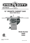
10” Left Tilt Contractor Saw
30” Rip Fence
Owner’s Manual
Model: 10-201
Record the serial number and date of purchase
in your manual for future reference.
Serial number:
Date of purchase:
233282
For more information:
www.rikontools.com or [email protected]
For Parts or Questions:
[email protected] or 877-884-5167
Part # 10-201M1
Safety Warning
IMPORTANT! Safety is the single most important consideration in the operation of this equipment. The following
instructions must be followed at all times.
There are certain applications for which this tool was designed. We strongly recommend that this tool not be modified and/
or used for any other application other than that for which it was designed. If you have any questions about its application,
do not use the tool until you have contacted us and we have advised you.
General Safety Warnings
KNOW YOUR POWER TOOL. Read the owner’s manual carefully. Learn the tool’s applications, work
capabilities, and its specific potential hazards.
ALWAYS GROUND ALL TOOLS.
If your tool is equipped with a three-pronged plug, you must plug it into a three-hole electric receptacle.
If you use an adapter to accommodate a two-pronged receptacle, you must attach the adapter plug to a
known ground. Never remove the third prong of the plug.
ALWAYS AVOID DANGEROUS ENVIRONMENTS.
Never use power tools in damp or wet locations. Keep your work area well lighted and clear of clutter.
ALWAYS REMOVE THE ADJUSTING KEYS AND WRENCHES FROM TOOLS AFTER USE.
Form the habit of checking to see that keys and adjusting wrenches are removed from the tool before
turning it on.
ALWAYS KEEP YOUR WORK AREA CLEAN. Cluttered areas and benches invite accidents.
ALWAYS KEEP VISITORS AWAY FROM RUNNING MACHINES.
All visitors should be kept a safe distance from the work area.
ALWAYS MAKE THE WORKSHOP CHILDPROOF.
Childproof with padlocks, master switches, or by removing starter keys.
NEVER OPERATE A TOOL WHILE UNDER THE INFLUENCE OF DRUGS,
MEDICATION, OR ALCOHOL.
ALWAYS WEAR PROPER APPAREL.
Never wear loose clothing or jewelry that might get caught in moving parts. Rubber-soled footwear is
recommended for the best footing.
ALWAYS USE SAFETY GLASSES AND WEAR HEARING PROTECTION.
Also use a face or dust mask if the cutting operation is dusty.
NEVER OVERREACH.
Keep your proper footing and balance at all times.
NEVER STAND ON TOOLS.
Serious injury could occur if the tool is tipped or if the cutting tool is accidentally
2
ALWAYS DISCONNECT TOOLS.
Disconnect tools before servicing and when changing accessories such as blades, bits, and cutters.
ALWAYS AVOID ACCIDENTAL STARTING.
Make sure switch is in “OFF” position before plugging in cord.
NEVER LEAVE TOOLS RUNNING UNATTENDED.
ALWAYS CHECK FOR DAMAGED PARTS.
Before initial or continual use of the tool, a guard or other part that is damaged should be checked to
assure that it will operate properly and perform its intended function. Check for alignment of moving
parts, binding of moving parts, breakage of parts, mounting, and any other conditions that may affect its
operation. A guard or other damaged parts should immediately be properly repaired or replaced.
Special Safety Rules For Table Saws
1. Always wear eye protection.
2. Keep hands away from the saw blade while machine is running.
3. Always use blade guard during normal cutting operations.
4. Always use splitter during normal cutting operations.
5. Use push sticks when ripping narrow stock.
6. Always use fence while ripping and miter gauge while cross-cutting.
7. Never reach over or behind saw blade while machine is running.
8. Do not remove cut-off or jammed pieces until blade has come to a full stop.
9. Disconnect machine from power source before making repairs or adjustments.
10. Do not expose saw or power cord to water or use in damp locations.
California Proposition 65 Warning
WARNING: Some dust created by power sanding, sawing, grinding, drilling, and other construction activities contains
chemicals known to the State of California to cause cancer and birth defects or other reproductive harm.Your risk from
exposure to these chemicals varies, depending on how often you do this type of work. To reduce your exposure, work in
a well-ventilated area and with approved safety equipment, such as dust masks that are specially designed to filter out
microscopic particles.
For more detailed information about California Propostion 65 log onto rikontools.com.
SAVE THESE INSTRUCTIONS.
Refer to them often.
3
Table of Contents
Safety Warnings......................................................................................................................................2-3
Table Saw Safety Rules....................................................................................................................... 3
Specifications.........................................................................................................................................................4
Unpacking and Contents..................................................................................................................................... .5
Getting to Know Your Table Saw..............................................................................................................6
Assembly..............................................................................................................................................................7
Adjustments ..................................................................................................................................................15
Operations ..............................................................................................................................................19
Maintenance ......................................................................................................................................................24
Electrical Requirements .......................................................................................................................25
Grounding Instructions .........................................................................................................................26
Parts Explosion & List .................................................................................................................................. 27
Warranty .............................................................................................................................................. 37
Specifications
10-201
1.5HP
13/6.5
120/240 60Hz
3450RPM
Left
10”
5/8”
11-39/64”(W)x27”(D)
40”(W)x27”(D)
13-45/64”(W)x27”(D)
14-29/32”(W)x27”(D)
12/1/2”
30”
20”
3-3/8”
Model Number
Motor Induction
Amps
Volts/Hertz
Motor/Blade Speed
Blade Tilt
Blade Diameter
Blade Arbor
Table Size w/o Wings
Table Size with Wings
Left Wing Dimension
Right Wing Dimension
Table Front of Blade
Rip Capacity (Right)
Rip Capacity (Left)
Max Depth of Cut @ 90°
4
Contents of Package
Unpacking and Checking Contents
Unpack your 10-201 Contractor Saw from its carton and check to see that you have all of the
following items. Do not turn your saw ON if any of these items are missing. You may cause injury to
yourself or damage to your machine. If any parts are missing contact RIKON Technical Support at
1-877-884-5167 or [email protected].
A) Blade Guard and Splitter Assembly
B) On/Off Switch
C) Miter Gauge
D) Blade Wrench
E) Blade Wrench
F) Handwheel Assembly(2)
G) Handwheel Lock Knob(2)
AA) M4x8mm ROUND HD TAP SCREW (2)
AB) WRENCH HOOK
AC) M8 HEX NUT (2)
AD) M8 SPRING WASHER (2)
AE) M8 FLAT WASHER (2)
AF) M8X16mm CARRIAGE SCREW (2)
AG) FENCE BRACKET (2)
5
Getting to Know Your Table Saw
B
A
E
H
C
F
D
G
I
A) Miter Gauge
B) Blade Guard Assembly with riving knife
C) Motor Cover
D) Bevel Scale
E) Height Adjustment Handwheel
F) Bevel Adjust ment Handwheel
G) Fence Hooks(2)
H) On/Off Switch
I) Mobile Base Caster Assembly
6
1. Attach leg assemblies (A) to the right (J) and left (k)
of the table saw cabinet by placing (B) eight
M8X16mm carriage screws through the mounting
holes and place an M8 flat washer, M8 lock washer
and M8 hex nut onto each of the eight screws
attaching leg assembly to cabinet. Do not completely
tighten hardware at this time.
2. Attach two tie bars(C) and (H) between right and left
legs inside and tighten them with (D) eight M8X16mm
carriage screwsM8 flat washersM8 lock washers
and M8 hex nuts.
3. Attach middle bar (E) between tie bar (H) and (C)
inside, using four M8X16mm carriage screwsM8 flat
washers M8 lock washers and M8 hex nuts to tighten
it. SEE FIG.1
4. To tighten the legs (A) and tie bar (C) by two (L)
M8x45mm hex soc head screws, M8 flat washers, M8
lock washers;
5. Attach Mobile base caster assembly (I) to the tie bar
(H) and using two M8X16mm carriage screws and M8
flange hex nuts to tighten it.
6. Place two leveling screws (G) to the lags (A) and
place an M8 flat washer, M8 lock washer and M8 hex
nut onto each of the two screws and tighten them.
7. Attach two caster wheels(F) to the tie bar(C) and
place two M8x55mm hex soc head screws through the
mounting holes of the bar and wheels, and using M8
lock nut to tighten them. SEE FIG.1
• The table saw is a heavy machine; two people may be
required for certain assembly operations.
• DO NOT assemble the table saw until you are sure the
tool is unplugged.
• DO NOT assemble the table saw until you are sure the
power switch is in the "OFF" position.
• For your own safety, DO NOT connect the machine to
the power source until the machine is completely
assembled and you read and understand this entire
User Manual.
INSTALLATION AND LEVELING
Final location for the saw must be level, dry, well lighted,
and have enough room to allow movement around the
saw with long pieces of wood stock.
Level the saw front to back and side to side. If necessary,
but make sure the saw is stable before being placed in to
service.
CABINET LEG ASSEMBLY
Fig.2
1. Turn the table saw side lay. CAUTION: The table saw
is heavy; two people are required for this operation. Be
sure to lay cardboard on the floor to protect the table
and cabinet.
Fig. 1
I
G
H
K
E
D
B
A
7. To align the hole of cabinet with the hole of cabinet
leg, and using eight M8x20mm hex head screws, M8
flat washersM8 lock washers and M8 hex nuts to
tighten them. SEE FIG.2 & FIG.3
J
L
C
F
L
7
Fig.3
2. Thread the locking knob (D) onto the threaded end of
the shaft. SEE FIG 5.
3. Repeat the steps above to assemble the remaining
handwheel and locking knob onto the bevel shaft
located on the side of the cabinet.
WRENCH AND FENCE HOOK
ASSEMBLY
Fig.6
HANDWHEEL ASSEMBLY
A
D
B
Fig.4
C
A
B
C
1. Place one of the handwheels (A) onto the blade
raise/lower shaft (B) located on the front of the
cabinet. Align the groove in the back of the
handwheel with the pin (C). SEE FIG 4.
1. Assemble both of the fence hooks (C) to the left and
right cabinet leg (B) using four M8x16mm
carriage screws, M8 flat washer, M8 lock washer and
M8 hex nut to tighten them.
2. Assemble wrench hook (A) to the right side of cabinet
(D) using two M4X8mm round head tap screws.
SEE FIG 6
Fig.5
POLY-V BELT REPLACEMENT
1. Loosen 6 of M5x10mm cross pan head tap screws (A)
and remove the cabinet access door. SEE FIG. 7.
D
8
Fig.7
EXTENSION WING ASSEMBLY
A
CAUTION: The extension wing is heavy; two people are
required for assemble. The installation method for
granite and cast iron wing is the same.
1.One person put right/left extension wing on the top of
cabinet. Alignment pin into bottom of wing (A).
SEE FIG.10
2. Install the belt on the Arbor Pulley and raise motor
by loosing 1 of the motor mounting screws (B) to
reach the belt distance for assembling the belt on
the motor Pulley. SEE FIG.8 & FIG.9
Fig.10
Fig.8
A
B
2. Another
Anothe person
perso locks
lock 4 bolts
bolt (B)
(B with
wit flat
fla and
an spring
washer and
washe
an from
fro the
th bottom
botto of cabinet
cabine and
an tighten
tighte it.
SEE FIG
SE
FIG. 10
Fig.9
B
NOTE: Step1 and step2 can complete
the assembly for extension wings easily.
Need not
no adjust
adjus the
th flatness
flatnes for
Nee
extension
extensio wings
wing after
afte assembling.
Because
Becaus we have
hav done
don the
th preadjustment
adjustmen and
an pre-setting
pre-settin of the
extension
extensio wings
wing for
fo the
th flatness
flatnes in
factory.
factor
3. Replace the cabinet access door.
9
3. The user can adjust the flatness for the extension
Wings to obtain more flatness. We suggest that user
need not do this adjustment again, the process are as
following if user want to do the adjustment again.
4.To loose 4 screws (B) by 6.0mm Allen Wrench;
5.To loose 4 setting screws (C) by 2.5mm Allen wrench.
SEE FIG.12
8. Make sure both wings are aligned, if not, refer to step
(6) until completely adjusted.
9. Using a 6.0mm Allen wrench to secure 4 screws (B).
Fig.12
C
6.Using an open wrench to adjust the 4 elevation
screws (E) to raise or lower the extension wing to the
table. SEE FIG.13
Fig.13
E
7.Use a straight edge across to the main table and
extension wings, checking the flatness of both main and
extension wings. SEE FIG.14
Fig.14
10
4. Connecting the right guide tube(long)and left guide
FENCE ASSEMBLY
tube(short)with cap (D), and place them on the front
rail.
5. The guide tube must be fasten by eight M6X16mm
hex soc round head screws(C) with M6 flat washer
and M6 lock washer. SEE FIG.19
1. Fasten the front rail to the table top using four
5/16-18x5/8mm cup hex soc head screws (A)
Fig.20
SEE FIG.17
Fig.17
G
F
E
G
A
7. Place the Fence Body (E) on the table top and
2. Fasten the left rear rail to the table using two
5/16-18x5/8mm hex head screws(B) with M8 flat
against the blade to make sure that if the "zero"
Washer and M8 lock washer. SEE FIG.18
scale on the cursor (F) is align with the "zero" scale of
the right/left scale label stuck on the guide tube.
Fig.18
8. Loosen the pan head screw (G) and move the cursor
(F) till the zero scale aligns with the zero scale on the
right/left scale. SEE FIG.20
B
3. The installation method for right rear rail is the same
As the left one.
Fig.19
D
C
11
RIVING KNIFE/SPLITTER COMPONENTS
ASSEMBLY
Fig.22
Note: Remove the table insert ( Table insert are gripped
by four magnets on the table).
Fig.21
B
C
Fig.23
INSTALLING AND REMOVING
THE RIVING KNIFE/SPLITTER
1. Loosen the knob (C),Line up the riving knife/splitter in
the proper direction to the mounting bracket (B).
SEE FIG22.
C
2. Push the Riving Knife/splitter all the way down into the
mounting bracket, make sure the location pin is
properly locked in the hole of the Riving Knife/splitter.
(The location hole is on the button side of the Riving
Knife/splitter).
BLADE ASSEMBLY
3. Tighten the fasting knob(C). SEE FIG.23
•Remove
Fig. 24
1. Loosen the fasten knob (C).
2. Remove the Riving Knife/splitter out of mounting
bracket.
NOTE: Make sure blade or arbor is at the highest
position before adding or removing the riving
Knife/splitter.
12
1. Remove the hex nut (K) and outer flange (J) from the
blade arbor (I). Note: The arbor has a right hand
thread; to loosen the hex nut turn it counterclockwise.
CONVERSION THE SPLITTER TO RIVING
KNIFE
2. Place a 10" saw blade (Z) onto the blade arbor (I),
make sure the teeth of the blade are pointing down in
the front of the table saw. Place the outer flange (J)
and hex nut (K) onto the blade arbor and snug hex
nut by hand. Place the open-end blade wrench (L) on
the flats of the inner blade flange (not shown) and
the box-end blade wrench (M) onto the hex nut and
securely tighten.
Note: The blade arbor has a right hand thread, to
tighten the hex nut turn it clockwise. SEE FIG.24
Note: Splitter can be used as riving knife.
1. Remove the guard assembly(C) and kick-back pawl
assembly (D) by loosing knob (A) and (B). SEE FIG.27
Fig.27
Fig. 25
A
C
B
D
2. Remove the table insert, and make sure the location
pin inside the bottom of the mounting bracket is
properly insert into the location hole(E) of splitter.
SEE FIG.28
3. Place a square (N) onto the saw blade and against the
splitter assembly (O). Make sure the splitter is square
to table. SEE FIG.25
Fig.28
4. Lay a straight edge (R) against the left side of the saw
blade (S) Align the splitter and make sure the
splitter is aligned to the blade.
SEE FIG.26
E
Fig.26
F
3. Tighten the Knob (F) and re-install the table insert.
R
S
T
13
CONNECTING SWITCH CORD TO
MOTOR CORD
3. Pull slack in switch cord into the cabinet.
Make sure that the power cord inside of the cabinet
Is properly routed and clear of the saw blade and any
pinch points for all blade height and blade angle
Settings
Fig.30
1. Place the switch cord (A) through hole (B) in front of
Cabinet. SEE FIG. 29
2. Open motor cover, insert three prong switch cord (C)
into three hole outlet (D) of the motor cord.
SEE FIG,30
Fig.29
B
A
14
RAISING AND LOWERING THE BLADE
ADJUSTING BLADE BEVEL POSITIVE STOPS
Fig. 31
Fig. 32
A
A
C
B
B
1. To adjust blade to a 90-degree blade bevel positive
stop, raise the saw blade (A) to its highest position.
SEE FIG 32.
The blade height adjustment handwheel and handwheel
lock knob are located on the front of the cabinet above the
blade bevel scale. To raise the saw blade, loosen the
handwheel lock knob (B) (counterclockwise) and turn the
handwheel (A) clockwise. When the saw blade is at its
desired height, tighten the handwheel lock knob
(clockwise) until it is securely tightened. SEE FIG 31
2. Using a combination square (B) check that the blade is
90 degrees to the saw table (zero degrees on bevel
Scale).
3. If the blade will not tilt to 90 degrees, when the set
screw (C) contacts the position stop, and turn it until
the blade can be positioned to 90 degrees.
4. Once the blade has been tilted to 90 degrees (confirm
this using your square), tighten the bevel handwheel
lock knob, located on the side of the cabinet. This will
keep the blade from tilting further.
5. If the blade will not tilt to 45 degrees, when the set
screw (D) contacts the position stop and turn it until the
blade can be positioned to 45 degrees. SEE FIG 33
To lower the saw blade, loosen the handwheel lock knob
(counterclockwise) and turn the handwheel
counterclockwise. When the saw blade is at its desired
height, tighten the handwheel lock knob (clockwise) until it
is securely tightened.
TILTING THE BLADE
The blade bevel handwheel and handwheel lock knob are
located on the right side of the cabinet. To increase the
saw blade bevel, loosen the handwheel lock knob
(counterclockwise) and the adjustment knob (C) and then
turn the hand wheel clockwise. When the saw blade is at
its desired degree, tighten the handwheel lock knob
(clockwise) and the adjustment knob (C). SEE FIG.31
Fig. 33
C
To return the saw blade bevel to zero degrees, loosen
the handwheel lock knob (counterclockwise) and the
adjustment knob (C), then turn the handwheel
counterclockwise.
D
To tilt the blade bevel to 45-degrees, loosen the handwheel lock knob (counterclockwise) and the adjustment
knob and then turn the handwheel clockwise. When the
saw blade is at 45-degrees it will come into contact with
the adjustable positive stop which will cause the blade to
stop. Tighten the hand-wheel lock knob (clockwise)and the
adjustment knob until it is securely tightened.
15
Fig. 34
1. Raise the saw blade to its highest point.
2. Place a combination square (A) on the saw table with
one edge (B) of the square against the left miter slot
(C). SEE FIG 35.
3. Adjust the square so the rule (D) just touches the saw
blade. Make sure the rule is not touching any of the
carbide tips of the saw blade.
4. Lock the rule in this position.
Fig. 36
6. Using a combination square (C), make sure that the
blade is at 45 degrees. SEE FIG 34
7. With the blade at 45 degrees, tighten the bevel
handwheel lock knob to keep the blade from further
tilting.
8. Turn the set screw clockwise until it comes in contact
with the positive stop.
CHECKING BLADE ALIGNMENT
Blade heel is the misalignment of the blade to the miter
slots. This means that the blade is not parallel to the
miter slots. The blade is set parallel at the factory and
should not need any adjustments. You can check this by
using a dial indicator (not included) or a combination
square (not included). It is recommended to check the
alignment before initial operation as follows:
6. Rotate the saw blade back so that you take the
measurement from the same spot on the saw blade.
SEE FIG 36
7. Take a reading at the rear of the blade (E) with the
combination square. If there is a difference of more
than. 01 in between the rule and the blade, then an
adjustment will have to be made.
Fig. 35
ADJUSTING BLADE ALIGNMENT
NOTICE: Blade alignment is factory set and should not
need adjustment. All saw blades have some runout.
Therefore, readjusting the blade alignment should only be
attempted if it becomes necessary (see "CHECKING
BLADE ALIGNMENT")
16
1. To align the blade parallel to the miter slot, first
loosen two hex soc head screws (A) under the front
side of the table saw. This is the same side as the
raise/lower handwheel (B). SEE FIG. 37
BEVEL ARROW ADJUSTMENT
1. Make certain that the blade is at 90-degrees to the
table surface with a combination square.
Fig. 39
Fig.37
A
A
B
2. Remove the End cap on the rear side of the table
saw, Loosen two hex soc head screws (C). SEE FIG.38
2. Check that the bevel arrow is pointing to the zero
degree mark on the bevel scale located on the front
of the cabinet. SEE FIG 39.
Fig.38
3. To adjust arrow, loosen the Philips head screw (A),
and reposition the bevel arrow and tighten screw.
C
3. The saw table is now loose and can be repositioned
until the blade is parallel to the miter slot. Repeat
steps in "CHECKING BLADE ALIGNMENT."
4. When blade is parallel to miter slot, tighten all four
hex soc head screws.
5. Recheck blade alignment.
6. Tilt the blade to 45 degrees, and rotate the saw
blade by hand. Make sure the blade does not
contact the table insert.
17
TABLE INSERT ADJUSTMENT
1. The miter gauge has adjustable positive stops at 0degree and 45-degrees or it can be manually set at
any angle between 60-degrees.
2. To rotate miter gauge body (A), loosen knob (B) and
pull out plunger (C) and rotate miter gauge body to
desired angle and tighten knob. SEE FIG. 41
Fig. 40
3. To rotate to the next positive stop, pull plunger (C) out,
rotate miter gauge body then push plunger back in and
continue rotating miter gauge body until it stops
Against next positive stop.
ADJUSTING POSITIVE STOPS
C
Fig. 42
C
D
A
E
B
D
1. The table insert (A) must always be level with the saw
table (B).
2. Place a straight edge across the front and rear of the
table insert. Check that the insert is perfectly level with
the saw table.
3. To level the table insert, turn the one or more adjusting
set screws (C) as needed and recheck.
5. The table insert is equipped with a finger hole (D) for
easy removal. SEE FIG. 40
MITER GAUGE ADJUSTMENT
1. To adjust 0-degree positive stops, loosen knob (B), pull
out on plunger (C) and turn miter gauge over.
2. Loosen the lock nut (D) 3 or 4 turns. SEE FIG 42.
3. Place a square against the guide bar and front of the
miter gauge body. Square the miter gauge body to the
guide bar and tighten knob.
Fig. 41
4. Push in plunger and make adjustments to stop screw
(E) so that it touches the plunger and tighten lock nut.
B
5. Recheck the positive stop angle to the saw blade.
insert the guide bar into the miter slot and slide the
miter gauge up to the saw blade.
6. To check, place a square against the saw blade and
miter gauge body. If any more adjustments are needed
repeat steps above.
7. To set both 45-degree positive stops, repeat steps 1
Thru 6 above at the 45-degree settings.
C
A
18
3. To turn the table saw off, press the large red “OFF”
paddle (B) or lift the paddle and press directly on the
Red " OFF" button.
4. When the table saw is not in use, the "ON" button (B)
should be locked so that it cannot be started.
5. Using a padlock (not provided) , it is possible to lock
the switch to prevent unauthorized use. Lift the red
"OFF" paddle and place a padlock through the holes
(C) in the side of the "ON" button and then lock the
padlock. Make sure keys have been removed from
padlock and placed where no children can get them.
SEE FIG.43
A separate electrical circuit should be used for your
table saw. The circuit should not be less than #14
AWG wire and should be protected with a 15-amp
time lag fuse.
Have a qualified electrician repair or replace damaged
or worn cord immediately.
Before connecting the motor to the power line, make
certain the switch is in the “OFF” position and be sure
that the electric current is of the same rating as the
motor nameplate. All line connections should make
good contact.
Running on low voltage or long, under rated extension
Cords will damage the motor.
DO NOT expose the table saw to rain or operate the
in damp locations.
MAKE SURE all parts have been assembled
correctly and are in working order.
KEEP table surface clear of tools and debris before
starting table saw.
STARTING AND STOPPING THE SAW
Fig .43
THERMAL-OVERLOAD PROTECTION
Turn the power switch "OFF" and unplug the power
cord from its power source prior to doing or performing
any maintenance.
Make certain that the "OFF" button has been depressed
before pushing the thermal-overload reset button.
The motor supplied with your table saw has a (resettable)
thermal-overload relay located on the side of the switch.
If the motor shuts off during an operation (cutting a
workpiece too fast or using a dull blade, using the saw
beyond its capacity, or low voltage) press the "OFF"
button and let the motor cool three to five minutes.
1. The ON/OFF switch is located under the front rail on
the table saw.
2 To turn the table saw on, press the green ON button
(A) in one half inch. Note: There is a safety feature on
the switch to insure that the switch must be completely
pressed before the saw will start. SEE FIG.43
19
Push the reset thermal-overload button on the side of the
ON/OFF switch assembly. Make certain that the saw
blade and work are has been cleared of debris before
restarting saw. The motor can now be turned on again.
6. Is the guard assembly installed and functional?
7. Have you checked the saw blade clearance when it
is adjusted to varying angles and depths?
8. Have you read all the warnings and directions
regarding the operation of this machine?
TEST RUN
1. Face the table saw and stand to the left of the blade
path.
2. With one finger on the ON button and one finger on
the OFF button, turn the saw on. Be ready to turn the
saw off in case of a mishap.
3. Watch and listen to the saw. Note whether there are
any unusual sounds or excessive vibrations.
4. If anything appears abnormal, immediately turn off
the saw, unplug it, and fix the problems. If a problem
exists that is beyond the scope of this manual,
contact your dealer.
5. If the saw is operating properly, turn it off and
prepare to make a cut according to the instructions
outlined in this section.
BLADE SELECTION
Choosing the correct blade for the job is essential for
the safe and efficient use of your table saw. Ignoring
this important step could result in damage to the saw
and serious injury to the operator. Below are the most
common saw blades and their uses.
1. Rip Blade: Used for cutting with the grain. Typically,
10 rip blades have between 18-40 teeth and large
gullets to allow for large chip removal. SEE FIG 44.
The following section was designed to give
instructions on the basic operations of this table
saw. However, it is in no way comprehensive of
every table saw application. It is strongly
recommended that you read books, trade magazines,
or get formal training to maximize the potential of
your table saw and to minimize the risks.
Fig.44
PRE-RUN CHECK
Before you begin to use your Table Saw, you should
give it a thorough inspection, making sure you ask
yourself the following questions:
1. Is the blade mounted correctly?
2. Is the saw stable?
3. Is it wired properly?
4. Is the electrical system properly configured?
5. Have you checked your workpiece for obvious
Defects?
20
2. Cross-cut Blade: Used for cutting across the grain.
10 cross-cut blades have between 60-80 teeth and
a shallow gullet. SEE FIG 45.
5.Dado Blade: There are two types of dado blades:
stack and wobble. Stack dadoes involve more setup
time, but they provide a superior finish cut when
compared to a wobble dado. Dado blades require
13/16" max use of accessory dado table insert.
Fig.45
This section on blade selection is by no means
comprehensive.Always follow the saw blade manufacturer
recommendations to assure safe and efficient operation
of your table saw.
CROSSCUTTING
Crosscutting means cutting across the grain of the
wood. In wood products without grain (i.e. MDF,
particleboard), crosscutting simply means cutting
across the width of the stock.
Crosscuts are made with the miter gauge. There are
two miter gauge slots in the table top. Use the one that
works best for the piece being crosscut. To make a
crosscut using the miter gauge:
3. Used for cutting with and across the grain. A
compromise between a rip blade and a cross-cut
blade, a 10 combination blade will typically have
between 40-50 teeth. SEE FIG.46
1. Inspect the board for soundness. You do not
necessarily need a square edge to crosscut with
accuracy.
2. Inspect the miter gauge. Is it properly set and tight?
3. Move the rip fence completely out of the way.
4. Turn on the saw and allow it to come to full speed.
5. Hold the workpiece firmly against the face of the
miter gauge and ease it into the blade and through
the workpiece. SEE FIG.47
Fig.46
Fig.47
4.Thin-kerf blade: Most types of saw blades are
available in a thin-kerf style. Designed primarily to
minimize stock waste, thin-kerf blades are used in
conjunction with a blade stabilizer to reduce blade
wobble. Note: Many blade guards/splitters are
thicker than many thin-kerf blades. Make sure that
the stock will pass by the guard/splitter before
beginning a cut.
6. Turn off the saw and allow the blade to come to a full
Stop.
21
RIPPING
Do not stand directly behind the workpiece when ripping.
SEE FIG.49
Ripping means to cut with the grain of the wood. In
other materials such as MDF or plywood, ripping simply
means to cut lengthwise. To rip a board:
1.Inspect the board for soundness.You will need a
straight edge to rip with accuracy. Your workpiece may
need to be jointed flat before attempting to cut on the
table saw.
Fig.49
2.Set the rip fence to the desired distance from the
Blade. IF YOU ARE MAKING NARROW CUTS, USE A
PUSH-STICK. Serious injury can occur if you put your
hands close to the blade. A push-stick pattern has
been included at the end of this manual. Use it to
hold the workpiece against the table and fence and
push the workpiece fully past the blade. When a small
width is to be ripped and a push-stick cannot be
safely put between the blade and rip fence, rip a
larger piece to obtain the desired piece.
3.Turn on the saw and allow it to reach full speed. Place
the straight edge of the board against the rip fence
and the flat side on table top. Feed the work-piece
slowly and evenly into the blade. When ripping, always
stand off to the side of the workpiece and push it
through, making sure to keep your fingers out of line
with the blade. SEE FIG.48
DADO OPERATIONS
In addition to its ability to rip and crosscut lumber, the
table saw is also an invaluable tool for creating a
variety of dadoes. These non-through cuts can be
created with specially-designed stacking or wobbling
dado blades.
Fig.48
22
1. Remove the table insert, splitter guard, and regular
saw blade.
2. Attach and adjust the dado blade system as
recommended in the dado blade's instructions.’
3. Install the dado table insert.(Not included)
4. Raise the blade system up to the desired depth of
the dado. Make sure the dado blade will not cut
through the workpiece.
5. Reconnect the saw to the power source.
6. If dadoing along the length of your workpiece, adjust
the distance between the fence and the inside edge
of the blade to suit your needs. When cutting across
the wood grain, use the miter gauge as a guide
while dadoing. Remember: Never use the fence as
a stop in conjunction with your miter gauge.
7. Using a scrap piece as a test piece, switch on the
saw and take a pass over the dado blade.
8. If the cut is satisfactory, repeat with your finish stock.
9. Avoid taking too deep a cut in a single pass. Make
Incremental cuts to avoid kickback.
Proper dado operations will differ depending on the
blade system you choose. Consult the instructions
included with your dado blades for directions regarding
attachment and adjustment.
23
LUBRICATION
PROTECTION CAST IRON TABLE FROM
RUST
The table saw has sealed lubricated bearings in the
motor housing that do not require any additional
lubrication from the operator.
Use a wire brush to clean off the worm gears and
trunnions and apply a white lithium grease to keep
them lubricated.
The environment and frequency of human contact can
have a very detrimental impact on unpainted cast iron
surface. Moisture, humidity and oils ( from human
CLEANING
hands!)can cause the unpainted cast iron surfaces to
Keep the inside of the cabinet clear of saw dust and
wood chips. With the table saw unplugged, vacuum out
the inside of the cabinet or blow out the inside with an
air hose. Be sure to use air pressure no higher than 50
P.S.I. as high pressure air may damage insulation.
mar or rust, so it is important to conduct routine
maintenance to keep your table saw looking new.
Cleaning and waxing the cast iron surfaces on a regular
maintenance schedule is recommended as follows:
To clean and maintain the unpainted cast
iron surfaces:
• Apply a heavy coat of WD-40 onto the
unpainted cast iron surface.
• Use a fine steel wood pad to buff the
unpainted cast iron. Make sure to buff in a
“front-to-rear” direction only. A side-to-side
buffing motion will show in the finely ground
cast iron as a flaw, defector scratches.
• Reapply WD-40 and buff the unpainted cast
iron surfaces until the stains or rust are
removed. Make sure you use the same frontto-rear buffing direction to avoid scratching or
marring the cast iron surface.
• After all stains and/or rust have been
removed, clean all oil and dirt from the table
saw using a soft cloth or rag.
• Lastly, you need to apply a good automotive
paste wax to all unpainted cast iron surfaces.
This will help to protect the saw from rusting.
24
ELECTRICAL REQUIREMENTS
25
In the event of a malfunction or breakdown, GROUNDING provides the path of least resistance for electric
current and reduces the risk of electric shock. The plug
MUST be plugged into a matching electrical receptacle
that is properly installed and grounded in accordance
With ALL local codes and ordinances.
The smaller the gauge-number, the larger the diameter
of the extension cord is. If in doubt of the proper size of
an extension cord, use a shorter and thicker cord. An
undersized cord will cause a drop in line voltage
resulting in a loss of power and overheating.
If a plug is provided with your machine DO NOT modify
the plug. If it will not fit your electrical receptacle, have a
qualified electrician install the proper connections to
meet all electrical codes local and state. All connections
must also adhere to all of OSHA mandates.
USE ONLY a 3-wire extension cord that has a 3-prong
grounding plug and a 3-pole receptacle that accepts the
machine's plug.
IMPROPER ELECTRICAL CONNECTION of the
equipment-grounding conductor can result in risk of
electric shock. The conductor with the green insulation
(with or without yellow stripes) is the equipmentgrounding conductor. DO NOT connect the equipmentgrounding conductor to a live
If you are using an extension cord outdoors, be sure it is
marked with the suffix " W-A" ( "W" in Canada) to
indicate that it is acceptable for out door use.
Make certain the extension cord is properly sized, and in
good electrical condition. Always replace a worn or
damaged extension cord immediately or have it repaired
by a qualified person before using it.
Check with a qualified electrician or service personnel if
you do not completely understand the grounding
instructions, or if you are not sure the tool is properly
grounded.
Protect your extension cords from sharp objects,
excessive heat, and damp or wet areas.
The motor supplied with your machine is either a
120/240 dual voltage motor or a dedicated 240 volt.
Never connect the green or ground wire to a live
terminal.
The machine should only be connected to an outlet
having the same configuration as the plug.
26
PARTS LIST
27
KEY
NO.
PART
NO.
DESCRIPTION
1
91011618
RIGHT BLADE GUARD
2
91011619
SHOULDERED SCR
3
91011620
4
KEY
NO.
PART
NO.
DESCRIPTION
1
18
91011629
RIGHT ANTI KICKBACK FIGURE
1
2
19
91011630
TWIST SPRING
1
ROUND PIN
2
20
16000019
̛3X30mm SPRING PIN
1
12000445
M4X10mm ROUND HD CUTTING SCR
1
21
91011631
LEFT ANTI KICKBACK FIGURE
1
5
12000533
M4X6mm HEX SOC SET SCR W/FLAT POINT
2
22
91011632
ANTI KICKBACK FINGER SUPPORT
1
6
91011621
BLADE GUARD SUPPORT ARM
1
23
91011633
SPECIAL BOLT
1
6A
33000749C
WARNING LABEL
1
24
91011634
SPRING
1
7
12000524
M5X12mm HEX SOC SET SCR W/CONE POINT
1
25
91011635
FAST NUT BASE
1
8
91011622
FIXED SHAFT
2
26
91011636
RIVING KNIFE PLATE
1
9
91011623
7/32 STEEL BALL
2
27
91011637
RIVING KNIFE SUPPORT
1
10
91011624
SPRING
2
28
12000032
SCR SOC HD CAP M6 X 12mm
2
11
91011625
BUSHING
2
29
14000001
M6 LOCK WASHER
2
12000526
M6X8mm HEX SOC HD SCR WITH FLAT POINT 1
QTY
QTY
13
91011626
TWIST GRIP
2
29A
14
91011627
LEFT BLADE GUARD
1
29C
11000133
M8 BLOCKING NUT(LEFT)
15
12000401
M4X8mm COUNTERSUNK HD SCR
1
29D
12000527
M5X10mm HEX SOC HD SCR WITH FLAT POINT 1
16
91011628
RIVING KNIFE
1
29E
12000395C
ST2.9X6.5 CROSS COUNTERSUNK TAP SCR
2
17
14000019
̛12 FLANGE
2
29F
91011425C
ANTI KICKBACK FINGER SUPPORT BEARER
2
28
2
MITER GAUGE ASSY
29
KEY
NO.
PART
NO.
DESCRIPTION
40
91011664
LEFT EXTENSION WING 10”
41
12000004C
1/4-28 X 3/8" NYLON SET SCR
42
91011428
43
91011710
44
91011702
48
91011691
49
91011677
52
91011676
53
KEY
NO.
PART
NO.
DESCRIPTION
1
60
91011025
SWITCH PADDLE
1
4
61
12000008C
M4X25mm ROUND HD TAP SCR
2
TABLE INSERT LEFT PAD
2
62
91011033
SWITCH
1
TABLE INSERT RIGHT PAD
1
63
91011170
SWITCH BOX
1
TABLE INSERT
1
63A
33000001
SWITCH RESET LABEL
1
̛8X6mm MAGNET
4
64
12000009C
M4X16mm ROUND HD TAP SCR
4
TABLE ASSY
1
66
91011036
SWITCH SUPPORT
1
RIGHTEXTENSION WING
1
68
11000002C
M5 HEX NUT
2
12000529
5/16-18X55mm HEX SOC SET SCR
_
69
22000001C
M5 EXT TOOTH WASHER
4
54
12000505
5/16-18X28mmHEX SOC HD SCR
4
70
12000154C
M5X12mm PAN HD SCR
2
55
14000002C
M8 LOCK WASHER
12
73
71000001
RESET SWITH(25Amp,125/250V)
1
56
91011024C
SPECIAL WASHER
8.3X25X3.5)
12
74
71000002
JUMPER WIRE (BLAK)
1
75
91011038
ORD W/FEMALE DISONNETOR
1
75A
71000003
STRAIN RELIEF(7P-2)
2
76
91011039
POWER CORD
1
*
S00519C
MITER GAUGE ASSY
114
91011051
MITER GAUGE BODY
115
91011401
SPECIAL WASHER
1
116
91011053
SPECIAL SCR
2
119
91011326
GUIDE BAR
1
120
12000013C
M4X16mm SET SCR
4
121
91011057
1/4"X3/4 PIN
1
122
12000012C
M4X10mm PAN HD SCR
2
122A
13000004C
M4 FLAT WASHER
2
123
91011058
PLUNGER
1
124
91011059
PLUNGER BLOCK
1
125
91011172
CURSOR
1
126
12000014C
M4X15mm PAN HD SCR
1
127
12000015C
M4X20mm PAN HD SCR
3
127A
11000003C
M4 HEX NUT
3
130
35000003
MITER SCALE
1
131
91011024C
SPECIAL WASHER
1
132
91011286
MITER GAUGE KNOB
1
QTY
30
QTY
1
31
KEY
NO.
PART
NO.
DESCRIPTION
200
11000006
NUT L.H. JAM 5/8-18
201
11000011
M6 HEX NUT
202
91011287C
M5X12mm PAN HD SCR
203
18000001
(6203 LLB)
204
91011647
BUSHING
205
91011695
ARBOR PULLEY
206
91011648
207
KEY
NO.
PART
NO.
DESCRIPTION
1
245
91011214
KNOB END CAP
2
2
246
91011211
HANDWHEEL LOCK KNOB
2
3
247
12000171
SPECIAL HEX SOC HD SCR
1
2
247A
91060060
SPRING
1
1
247B
91060059
HANDLE
1
1
247C
91011665
BOLT
1
BUSHING
1
248
13000031C
WASHER
1
12000228
M8X8mm HEX SOC HD SCR
2
249
91011666
FRONT BRAKET
1
208
12000127
M6X10mm HEX SOC HDSCR
2
250
12000138C
M6X12mm PAN HD SCR
1
209
91011649
ARBOR RAISING SUPPORT BRACKET
1
251
91011667
POINTER
1
210
22000002
WAVE WASHER
1
253
12000310
M8 X 30mm HEX SOC SET SCREW
2
211
91011650
SPLITTER MOUNT SUPPORT
1
255
91011668
SHAFT
1
212
91011651
FLANGE
1
256
17000028
6X6X35 KEY
1
213
12000187
M5X12mm HEX SOC HD SCR
3
257
11000007C
M8 NUT
2
214
17000001C
5X5X15 KEY
1
258
91011024C
SPECIAL WASHER
1
215
91011652
ARBOR SHAFT (with 218# nut)
1
259
12000042
M8X40mm BOLT
1
1
259A
91011697
SHOULDERD SCREW
1
1
2
260
91011669
PLATE
1
260A
12000127
M6X10mm SCREW
2
216
91011715
BALL BEARING
BLADE(OD: 10" ID: 5/8" 40TH)
QTY
QTY
217
219
91011071
12000446
BLADE FLANGE
M6X35mm HEX SOC HD SCR
219A
13000002
M6 FLAT WASHER
2
261
91011670
SHOULDERD SCREW
1
220
12000017
M10X45mm HEX HD SCR
4
262
91011671
CONNCETING ROD
1
221
13000006
M10 FLAT WASHER
8
263
11000058
M6 NUT
2
222
91011653
REAR BRACKET
1
264
91011672
PIN
1
223
14000003C
M10 LOCK WASHER
4
265
12000530
M8X100mm BOLT
1
224
11000005C
M10 HEX NUT
4
266
91011673
MOTOR SUPPORT BRACKET
1
225
11000006
5/8-18 LOCK NUT
4
267
12000228
M8X8 SCREW
2
226
91011654
REAR TRUNNION
1
268
13000003C
M8 FLAT WASHER
2
227
91011655
TIE BAR
2
269
14000002C
M8 LOCK WASHER
1
228
91011656
EELEVATING SHAFT ASSY
1
270
11000007C
M8 HEX NUT
1
231
15000018
̛4X20mm SPRING PIN
1
271
15000030
PIN
1
232
22000005
3/8" FIBER WASHER
2
272
91011674
BELT
1
233
91011658
ECCENTRIC SCR
1
273
12000467
1/4-20X3/8mm HEX SOC SET SCR
2
234
12000125
M5X6mm HEX SOC HD SCR
1
274
17000002C
5X5X36mm KEY
1
*
91011659
BEVELING ASSY
1
275
33000978
MOTOR SPEC LABEL
1
235
19000043
̛9 WASHER
1
276
S00629
MOTOR ASSY (1.5HP)
1
236
91011660
BUSHING
1
277
91011519
MOTOR PULLEY
1
237
91011661
BEVELING ROD
1
278
91011675
FRONT TRUNNION
1
238
15000018
̛4X20mm SPRING PIN
1
280
91011508
7/8"X1/2" WRENCH
1
239
91011662
BEVELING NUT
1
281
91011517
OPEN END WRENCH
1
240
11000006
5/8-18 LOCK NUT
1
282
21000001
2.5MM ALLEN WRENCH
1
241
91011663
BUSHING
1
283
21000002
3MM ALLEN WRENCH
1
242
91011708
HANDWHEEL
2
284
21000003
4MM ALLEN WRENCH
1
243
91011210
ELEVATING KNOB ASSY
2
285
21000004
5MM ALLEN WRENCH
1
244
91011091
KNOB BOLT
2
286
21000005
6MM ALLEN WRENCH
1
287
21000006
1/8" ALLEN WRENCH
1
32
KEY
NO.
PART
NO.
DESCRIPTION
KEY
NO.
PART
NO.
DESCRIPTION
301
91011730
LEFT REAR RAIL
301A
91011370
REAR RAIL CAP
1
315
91011250AC
SUPPORT WASHER
2
2
316
91011251
TENSION CLIP
1
301B
91011731
RIGHT REAR RAIL
302
12000345C
5/16-18*5/8 BOLT
1
317
12000138C
M6X12mm PAN HD SCR
1
4
318
19000001C
E-RING
303
13000003C
2
M8 FLAT WASHER
4
319
91011252
HANDLE PIVOT SHAFT
1
304
305
14000002C
M8 LOCK WASHER
4
320
91011240
END CAP
4
91011706
HOOK
1
321
91011239
LOCK LEVER
1
306
12000127C
M6X10MM HEX SOC HD SCR
2
322
91011121
CLAMP CAM
1
306A
13000002C
M6 FLAT WASHER
2
326
35000385
SCALE, LEFT 20" CAPACITY
1
306B
14000001C
M6 LOCK WASHER
2
327
91011733
LEFT FRONT RAIL
1
307
91011732
ASS'Y
1
327A
91011734
RIGHT FRONT RAIL
1
307A
33000981
FENCE LABEL
1
328
91011243
RAIL CONNECTOR
1
308
91011248
PLASTIC PAD
1
331
35000384
SCALE, RIGHT 30" CAPACITY
1
309
12000172C
M6X15 HEX SOC HD SCR
2
338
91011735
FRONT RAIL BRACKET
1
310
12000012C
M4X10 PAN HD SCR
4
339
12000483
5/16-18*5/8 FLAT HD SCR
4
311
13000004C
M4 FLAT WASHER
4
340
13000002C
M6 FLAT WASHER
8
312
91011238
SCALE INDICATOR
2
341
14000001C
M6 LOCK WASHER
8
313
12000228C
M8X8mm SET SCR
2
342
12000352C
M6X16 HEX SOC HD SCR
8
314
91011525
SPECIAL SCREW NYLON
2
QTY
33
QTY
34
KEY
NO.
PART
NO.
KEY
NO.
PART
NO.
DESCRIPTION
401
12000152
M5X10mm SCREW
402
91011736
MOTOR COVER
6
426
12000176
M8X55 BOLT
2
1
427
91011703
LEVELING SCREW
402A
33000979
2
LABEL
1
428
33000977
NAME PLATE
402B
1
33000980
LABEL
1
429
91011740
PLATE
2
403
91011562
SCREW
8
430
33000951
BEVEL SCALE
1
404
91011680
PIN
2
431
91011136
INSULATOR
1
404A
91011709
PIN
2
431A
12000014
M4*15 PAN HD SCR
1
405
91011737
CABINET ASSY
1
431B
13000004
M4 FLAT WASHER
3
406
91011240
END CAP
3
431C
91011135
CABLE CLAMP
1
407
12000125
M5X6 SCREW
8
431D
11000003
M4 HEX NUT
1
408
91011137
WRENCH HOOK
1
432
91011741
CASTER ASSY
1
409
12000039C
M4X8 ROUNF HD TAP SCR
7
433
11000055
HEX NUT(M8 FLANGE)
2
410
91011745
ACCESS DOOR
1
434
91021005
CASTER ASSY
1
411
33000976
LABEL
1
435
12000045
5/16-18X4"HEX HD SCREW
1
412
91011683
PLATE
1
436
11000013
5/16-18 LOCK NUT
1
413
12000153
M5X10mm SCREW
2
437
19000002
EXT.RET.RING1/2"
2
414
11000080
M5 LOCKED NUT
2
438
91021006
PIN
1
415
91011684
PLATE
1
439
91011742
REAR WHEEL BRACKET
1
416
12000037C
1/4-20 x3/8 ROUND HD TAP
4
440
13000007
1/2" FLAT WASHER
2
417
91011738
LEG
4
441
91011743
FOOT PEDAL
1
418
91011686
FENCE BRACKET
2
442
12000041
M8X20 BOLT
8
419
12000181
M8X16mm BOLT
12
443
91011744
PLATE
1
419A
12000183
M8X15mm BOLT
10
444
12000266
M6X10 SCREW
4
420
13000003C
M8 FLAT WASHER
24
445
11000011
M6 HEX NUT
2
421
14000002C
M8 LOCK WASHER
24
446
91011696
DUST COLLECTING PLATE
1
422
11000007C
M8 HEX NUT
24
447
91011178
DUST PORT
1
423
91011739
CASTER ASSY
1
448
12000040C
1/4-20 x1/2 ROUND HD TAP
4
424
11000047
M8 LOCK NUT
2
449
91011287C
M5X12 PAN HD SCR
4
425
91021009
CASTER WHEEL
2
450
91011549
PUSH STICK
1
DESCRIPTION
QTY
35
QTY
Extension Wing Screw Package
Front/ Back Rail Screw Package
91011024C (8) A) 5/16-18*5/8 HEX SOC HD SCR
14000002C (8) B) M8 FLAT WASHER
12000529 (8) C) M8 LOCK WASHER
D) 5/16-18*5/8 HEX HD SCR
A) M8 FLAT WASHER
B) M8 LOCK WASHER
C) 5/16-18X55mm HEX SOC SET SCR
12000483
13000003C
14000002C
12000345C
(4)
(8)
(8)
(4)
A
A
B
B
C
D
E
C
Location Location
Rail Tube Screw Package
Cabinet Leg Assembly Screw Package
A) M8X20mm HEX HD SCR
B) M8 HEX NUT
C) M8 FLAT WASHER
D) M8 LOCK WASHER
E) M8X16mm CARRIAGE BOLT
F) M8X15mm SCR HEX SOC SET SCR
G) M6XP1.0X10mm HEX SOC HD SCR
H) M6 HEX NUT
12000041
11000007C
13000003C
14000002C
12000181
12000183
12000266
11000011
(8) A) M6 FLAT WASHER
(16) B) M6 LOCK WASHER
(18) C) M6X16 HEX SOC HD SCR
(18)
(8)
(10)
(4)
(2)
13000002C (8)
14000001C (8)
12000352C (8)
A
B
C
A
B
Location
C
G
Caster Wheel Screw Package
!
D
E
F
H
A) M8X16 CARRIAGE BOLT
B) M8 HEX FLANGE NUT
C) LEVELING SCREW
D) M8 HEX NUT
12000181
11000055
91011703
11000007C
(2)
(2)
(2)
(2)
Location
Fence Bracket, Hook & Switch Screw Package
A) M8X16 CARRIAGE BOLT
B) M8 FLAT WASHER
C) M8 LOCK WASHER
D) M8 HEX NUT
E) M4X8 TAP SCREW
F) M6 FLAT WASHER
G) M6 LOCK WASHER
H) M6X16 HEX SOC SCREW
12000181
13000003C
14000002C
11000007C
12000039C
13000002C
14000001C
12000352C
F
A
B
C
D
E
(2)
C
(2)
(2)
(2)
D
(1) Location
Location
(2)
(2) Dust! Chute / Port Screw Package
(2) A) 1/4-20 X 1/2 ROUND HD TAP SCREW
B) M5X12 PAN HEAD SCREW
A
B
12000040C (4)
91011287C (4)
G
Location H
Location
A
Location
B
!
WARNING
Location
Location
If any parts are missing, do not attempt to power cord and turn “ON” the machine. The machineplug in theshould only be
turned “ON” after all the parts have been obtained and installed correctly. For missing parts, contact us at 877-884-5167
or [email protected].
36
Warranty
5-Year Limited Warranty
RIKON Power Tools Inc. (“Seller”) warrants to only the original retail consumer/purchaser of our
products that each product be free from defects in materials and workmanship for a period of five
(5) years from the date the product was purchased at retail. This warranty may not be transferred.
This warranty does not apply to defects due directly or indirectly to misuse, abuse, negligence,
accidents, repairs, alterations, lack of maintenance or normal wear and tear. Under no
circumstances will Seller be liable for incidental or consequential damages resulting from
defective products. All other warranties, expressed or implied, whether of merchantability,
fitness for purpose, or otherwise are expressly disclaimed by Seller. This warranty does not cover
products used for commercial, industrial or educational purposes.
This limited warranty does not apply to accessory items such as blades, drill bits, sanding discs or
belts and other related items.
Seller shall in no event be liable for death, injuries to persons or property, or for incidental,
contingent, special, or consequential damages arising from the use of our products.
To take advantage of this warranty proof of purchase documentation, which includes date of
purchase and an explanation of the complaint, must be provided.
The Seller reserves the right to effect at any time, without prior notice, those alterations to parts,
fittings, and accessory equipment which they may deem necessary for any reason whatsoever.
To take advantage of this warranty, please fill out the enclosed warranty card and send it to:
RIKON Warranty
16 Progress Rd.
Billerica, MA 01821
The card must be entirely completed in order for it to be valid. If you have any questions
please contact us at 877-884-5167 or [email protected].
37
For more information:
16 Progress Rd
Billerica, MA 01821
877-884-5167 / 978-528-5380
[email protected]
www.rikontools.com
Copyright RIKON Power Tools, Inc. 2011
Printed in China 2/11
TSB 18
11.10
A T
T
E
N
T
I
O
N
The following procedure is to help you fine tune your table top, wings and miter slot.
When assembled correctly, your table top will be within .008-.010 and the miter slot will
be ¾” x 3/8”.
Extension Wing Assembly
1. Align two holes located on the left/right extension wings
to the two pins on the cabinet.
Miter Gauge Slot Adjustment
1. If the slot between main table and extensions is too
narrow, please loosen two pins of the table bottom, and
fine-tune by moving the extension outwards slightly until
the slot have enoght space for miter gauge to move
smoothly, then you can tighten two pins back slightly
2. After extensions wings are installed, screw in 5/16-18 Hex
Round Screws (4) to the extensions, but not too tight.
3. Locate the miter gauge in the T-slot on table top.
4. To measure the overall flateness, use a straight edge on
the table top. If the flateness is acceptable, no need to
make any adjustment. If it's not satisfacotry, use the
leveling screw of the table bottom and set screws to
adjust the flatness
2. If the slot between main table and extensions is too
wide, please loosen two pins of the table bottom, and
fine-tune by moving the extension forwards slightly until
the slot have enoght space for miter gauge to move
smoothly, then you can tighten two pins back slightly
TSB 19
11.10
A T
T
E
N
T
I
O
N
The following information is an add-on page designed to provide extra details in
assembling the 10-201 Contractor Table Saws. Please see the location images as
an reference during assembling.
Extension Wing Screw Package
A) M8 FLAT WASHER
B) M8 LOCK WASHER
C) 5/16-18X55mm HEX SOC SET SCR
Front/ Back Rail Screw Package
91011024C (8) D) 5/16-18*5/8 HEX SOC HD SCR
14000002C (8) E) M8 FLAT WASHER
12000529 (8) F) M8 LOCK WASHER
G) 5/16-18*5/8 HEX HD SCR
12000483
13000003C
14000002C
12000345C
(4)
(8)
(8)
(4)
D
A
B
E
F
G
Z
C
Location Location
Rail Tube Screw Package
Cabinet Leg Assembly Screw Package
H) M8X20mm HEX HD SCR
I) M8 HEX NUT
J) M8 FLAT WASHER
K) M8 LOCK WASHER
L) M8X16mm CARRIAGE BOLT
M) M8X15mm SCR HEX SOC SET SCR
N) M6XP1.0X10mm HEX SOC HD SCR
O) M6 HEX NUT
12000041
11000007C
13000003C
14000002C
12000181
12000183
12000266
11000011
(8) P) M6 FLAT WASHER
(16) Q) M6 LOCK WASHER
(18) R) M6X16 HEX SOC HD SCR
(18)
(8)
(10)
(4)
(2)
13000002C (8)
14000001C (8)
12000352C (8)
R
H
I
Location
J
N
P
Q
!
K
L
M
O
Location
WARNING
If any parts are missing, do not attempt to plug in the
power cord and turn “ON” the machine. The machine
should only be turned “ON” after all the parts have been
obtained and installed correctly. For missing parts,
contact us at 877-884-5167 or [email protected].


