1
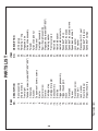
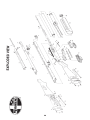
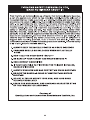
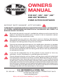
OWNERS
MANUAL
FOR 500®, 505™, 535™, 590®
AND
835®®MODELS
AND 590®
500®, 835
PUMP ACTION SHOTGUN
SHOTGUNS
IMPORTANT “SAFETY WARNINGS” - NOTE THE SYMBOL
These safety warnings are for your protection as well as the safety
of others. Disregarding information in this manual may result in
serious injury or death.
Be certain this owner’s manual is available for reference and is kept with this
firearm if transferred to another party. If manual is lost or misplaced, contact
Mossberg for a free replacement copy.
After performing any work on your firearm such as cleaning, adjustments,
disassembly or installation of any accessory, the firearm should be re-checked
for proper functioning before firing live ammunition.
Firearms are complicated mechanisms. Any modification, alteration, or improper
fitting of parts may result in a dangerous malfunction, damage to the firearm
and injury to the shooter and other persons. The firearm’s owner is responsible
for the correct reassembly and functioning of the firearm after any disassembly
or replacement of parts.
If you do not understand any of the material in this manual or have any
questions, contact Mossberg or a qualified gunsmith directly.
Do not attempt to load or use any firearm until you have read and understood
the information contained in its owner’s manual. Before handling your firearm,
you should learn how it operates and how to maintain it. This includes knowing
its basic parts, how the manual safety and other safety features operate, how to
safely open and close the action and how to safely load and unload ammunition
from the firearm. Improper use and handling is dangerous and could cause serious
injury or death to you or those around you. All users of the firearm must become
thoroughly familiar with the instructions in this manual.
O.F. MOSSBERG & SONS, INC.
P.O. BOX 497 • 7 GRASSO AVENUE, NORTH HAVEN, CONNECTICUT 06473
PHONE (800) 363-3555
www.mossberg.com
Safety and safe firearms handling is everyone’s responsibility.
As the owner of a firearm, you must undertake the full-time responsibility of
safe firearms handling for your own safety and the safety of those around you:
• Keep all firearms and ammunition out of the reach of children.
• Store your firearms and ammunition separately.
• Never store a loaded firearm.
• Never leave a loaded firearm unattended.
• Never transport a loaded firearm in a vehicle.
• Unload your firearm when you have stopped shooting and when you have to
climb a tree, fence, cross a slippery surface or have to transport it in a
vehicle.
• Do not load your firearm before you are in a place where it is safe to shoot
and keep your finger off the trigger until you are on target and have decided
to fire.
• Never shoot at water, rocks or any hard surface. Shots may glance off such
surfaces and cause injuries.
• Do not use alcohol or drugs before or while handling firearms.
• Do not touch trigger while the safety button is being engaged or disengaged.
Always point the muzzle of your firearm in a safe direction, regardless of whether
the firearm is loaded or unloaded.
Always treat every firearm as if it were loaded. Give your firearm to someone
with the action open (bolt fully rearward) and safety fully rearward in the “ON”
(SAFE) position after you verify the firearm is unloaded. Insist on the same
procedure when receiving a firearm from someone else. Learn the location of
all the safety features of your firearm and how they operate.
Wear eye and ear protection when shooting. Shooting without proper ear
protection can cause hearing damage. The use of eye protection during any
type of shooting is important to protect your eyesight.
Due to the heavy recoil of a shotgun, maintain an adequate distance between the
rear of the scope (if equipped) and your face at all times. Be certain the scope
installation does not interfere with access to, or the proper functioning of the
safety button.
We specifically disclaim any responsibility for damage or
injury whatsoever occurring in connection with, or as
a result of, the use of faulty, or non-SAAMI standard, or
“remanufactured” or hand-loaded (reloaded) ammunition.
Additionally, we disclaim any responsibility for damage or
injury which results from any modifications or changes
that are not a part of the firearm as delivered from the
factory.
Learn to clean your firearm thoroughly and make certain no oil, grease or other
materials are blocking the barrel. Obstructions of any kind can cause damage
to the firearm and may result in serious personal injury to the shooter and/or
others nearby.
Practice proper firearm maintenance and safety. Make sure all exposed metal
surfaces are coated with a thin film of oil, especially after exposure to damp
weather. (See proper section of this manual for cleaning instructions.) Do not
plug barrel or store in fabric-lined case which will absorb lubricants from the
firearms. Before using after storage, follow complete instructions stated in this
manual for refamiliarization with the firearm. A thorough inspection and function
test should be performed before going into the field. Have your firearm
periodically checked by a qualified gunsmith.
PART NO. 12173
REV. Q
A note about the warnings and information contained in this Manual:
We strongly suggest that you check with your local licensed retailer or state
police for additional information concerning firearms ownership, or hunting or
target shooting rules that may be required by local law or regulation. Since such
rules and regulations are subject to change, local authorities are in the best
position to advise you on such matters.
TABLE OF CONTENTS
Page
Operating Instructions . ....................................................................................... 2
Mechanical Safety ............................................................................................... 2
Barrel Assembly .................................................................................................. 3, 4
Magazine Capacity . ............................................................................................ 4
Loading ............................................................................................................... 5-6
Firing the Shotgun ............................................................................................... 6
Unloading the Shotgun ....................................................................................... 7
Disassembly Procedures . ................................................................................... 7-10
Cleaning and Lubrication .................................................................................... 10
Assembly Procedures ......................................................................................... 11-13
Function Testing .................................................................................................. 13
Sight Adjustment . ............................................................................................... 13
Accessory Barrels ............................................................................................... 14
Pistol Grip Installation ......................................................................................... 14
Speedfeed® Stock ............................................................................................... 15, 16
Heat Shield .......................................................................................................... 16, 17
Dual-Comb® Stock .............................................................................................. 17
Accu and Accu-Mag Choke Tubes ..................................................................... 17-20
Muzzleloader Barrels ........................................................................................... 20
Service Instructions . ........................................................................................... 21
Warranty Information............................................................................................ 22
Notes ................................................................................................................... 23-27
Parts List ............................................................................................................. 28
Exploded View . ................................................................................................... 29
The Basic Rules of Safe Firearms Handling ........................................................ 30
OPERATING INSTRUCTIONS
Read and understand this entire manual and its safety warnings before handling this firearm.
MECHANICAL SAFETY
The safety button is located on the top rear portion of the receiver (Fig. 2) and must be
manually moved to the desired position by the shooter.
To put the safety in the “ON” (SAFE) position, the safety button must be moved
fully rearward into the safety detent. The button will now cover the red dot. The red
dot is a training aid used only to show the direction of the “ON” (SAFE) position and
should not be used as an indicator that the safety is “on” or “off” (Fig. 2). Moving the
safety button forward toward the muzzle of the shotgun will put the safety in the “OFF”
(FIRE) position.
Remember, a firearm’s manual safety is a mechanical device which can never
replace safe firearm handling practices.
Never rely on any mechanical mechanism or safety device to prevent the
dangers of careless handling or pointing a firearm in an unsafe direction.
OFF:
FORWARD
AS SHOWN
ON:
FULLY REARWARD
Fig. 2
ACTION RELEASE CONTROL
The action lock lever is located on the left side of the trigger housing just rearward of the
trigger guard.
The action lock lever allows the action to be unlocked and opened for inspection of the
chamber and action or unloading without pulling the trigger. The action may be opened
by depressing the lever and pulling the forearm rearward (Fig. 3).
NOTE: During firing, the action unlocks automatically after the hammer falls and
the action can be cycled without depressing the action lock lever.
Fig. 3
2
BARREL ASSEMBLY
Barrels are not interchangeable between model numbers, gauge or capacity.
500®, 505™, 535™, 590® and 835® barrels are interchangeable only with barrels
of the same model, gauge and capacity.
CAUTION: Never close the action or pull the trigger while the barrel is removed as
damage could result to the firearm.
To facilitate shipping, some models are packaged with the barrel removed. A front swivel
stud and washer are also shipped separately on some models (see items 35 and 36 in
the exploded view). To install the barrel in the receiver, proceed as follows:
Visually and physically inspect the chamber and bore of the barrel to make
certain it is unloaded and that it is free of any obstructions, excessive oil or grease.
If you are unable to remove all obstructions, bring the firearm to a qualified
gunsmith or send it to the authorized Product Service Center. Obstructions of
any kind can cause damage to the firearm and may result in serious personal
injury to the shooter and/or others nearby.
Move the safety button fully rearward to the “ON” (SAFE) position (Fig. 2).
All Models: Depress the action lock lever, (Fig. 3) and move the forearm rearward until
the front of the bolt is in the middle of the ejection port (Fig. 7).
CAUTION: Wear eye protection.
590®/835® Models: Unscrew the magazine cap by turning it counterclockwise.
Slide the barrel takedown mount ring over the magazine tube while guiding
the barrel extension portion of the barrel into the receiver (Fig. 4).
Gently rotate the barrel back and forth while pushing the barrel into the
receiver.
Slide the barrel into the receiver and tighten the magazine cap, finger
tight only. DO NOT use pliers or a wrench to tighten magazine cap.
If your 590/835 shotgun is equipped with a magazine spring retainer,
prior to putting on the magazine cap, assemble the magazine spring
retainer over the protruding magazine spring. Push the retainer
downward inside magazine tube so that the spring retainer is flush with
the magazine tube end.
TAKEDOWN SCREW (500®, 505™, 535™)
3
CAUTION:
The magazine spring exerts pressure on the retainer. Use caution when
disassembling.
To disassemble: Pry up at various points around the small hole in the
center of the magazine spring retainer. Cup hand over retainer and
magazine so as to keep spring and retainer confined. Use caution not
to bend or distort the magazine tube end and or threads.
500®, 505™ and
535™ Models:
Slide the barrel into the receiver and tighten the takedown screw, finger
tight only. DO NOT use pliers or a wrench to tighten the takedown screw.
A little space between the magazine tube and the takedown mount is
normal.
WARNING (all models): Check to be certain that the barrel is fully seated into the
receiver by looking through the ejection port. The barrel extension must rest firmly
against the corresponding cut in the top of the receiver as shown in Figure 4.
Swivel Stud
Installation:
Place the washer over the swivel stud thread. Screw the stud into the
magazine cap and tighten, making sure the through-hole is oriented
horizontally. Use caution not to over-tighten the stud as this may strip
the threads in the magazine.
MAGAZINE CAPACITY
835® Models: Total ammunition capacity (including one in the chamber) is six (6)
2-3/4” or 3” or five (5) 3-1/2” shells.
535™ Models: Total ammunition capacity (including one in the chamber) is five (5) 2-3/4”
or 3” and four (4) 3-1/2”shells. Depending upon tolerance variations, total
capacity may be reduced by one round when using 3” shells.
500® Models: Total ammunition capacity (including one in the chamber) is six (6) 2-3/4”
shells. Depending upon ammunition tolerance variations, total capacity may
be reduced by one round when using 3” shells.
505™ Models: Total ammunition capacity (including one in the chamber) is five (5) 2-3/4”
or five (5) 2-1/2” shells. Depending upon ammunition tolerance variations,
total capacity may be reduced by one round when using 3” shells.
590® Models: Total ammunition capacity (including one in the chamber) is nine (9) 2-3/4”
or eight (8) 3” shells.
NOTE:
To comply with U.S. migratory bird laws, all five and six shot models are
shipped with a wooden dowel inserted in the magazine tube which limits
magazine capacity to two (2) shells.
835® Models:
To remove the dowel, first remove the barrel. Point the shotgun downward
and shake it back and forth lightly until the dowel falls out.
To change back to a 2-shot magazine capacity insert the dowel through the
center of the magazine spring so that it is positioned inside the coils of the
spring.
500® Bantam™
Model, Super
Bantam and
505™ Models:
This Model is supplied as a single shot. An extra long wooden dowel
blocks magazine loading. After proper firearm training the dowel can
be removed to cut to 9” to comply with appropriate laws. See below
for removal instructions.
500® and 535™ Models:
To remove the dowel, first remove the barrel. Point shotgun downward and
shake it back and forth lightly until the dowel protrudes from the
takedown screw hole in the end of the magazine tube. A rubber “O”
ring on the dowel prevents it from falling out accidentally. Grasp the
dowel and pull it completely out.
4
LOADING
Before loading, move the safety button fully rearward (Fig. 2) to the “ON” (SAFE)
position.
During loading, never allow fingers or any objects to contact the trigger. Keep the
muzzle pointed in a safe direction at all times.
Depress the action lock lever (Fig. 3) and open the action by pulling the forearm
completely rearward.
Do not load firearm until ready to use! Unload firearm when shooting has been
completed! The safety button should always be fully rearward in the “ON” (SAFE)
position whether or not the firearm is loaded.
Inspect the chamber and bore of the barrel for any obstruction, excessive oil or grease.
(The chamber is the rear portion of the barrel which contains the cartridge (Fig. 4).)
Obstructions of any kind can cause damage to the firearm and may result in
serious personal injury to the shooter and/or others nearby.
Check to be certain that the ammunition selected is the same type of cartridge as
designated on the left side of the barrel.
835® Models are designated to fire 12 gauge 2-3/4”, 3”, or 3-1/2” factory loaded ammunition.
Do not fire slugs of any type (single projectile ammunition) through the overbored 835
Accu-Mag barrel. This barrel is designated to shoot lead or steel pellet shot loads only. Use
only 835 barrels designated specifically for slug shooting.
535™ Models are designed for factory loaded 2-3/4”, 3”, and 3-1/2” shells and rifled
slugs.
590® Models handle 12 ga. 2-3/4” or 3” magnum shells. 500® and 505™ Models
are designed for 2-3/4” (2-1/2” .410 bore) and 3” magnum shells within gauge.
Fully rifled barrels deliver best accuracy with sabot style slugs. “Rifled” slugs and shotshells are
not recommended for use in rifled barrels.
If you wish to load the firearm with the maximum number of shells, or fire single shots, load the
first shell through the ejection port located on the right side of the receiver (Fig. 5). The shell can
be inserted directly into the chamber or placed on top of the elevator. Close the action by moving
the forearm completely forward. Be sure to leave the safety “ON” (fully rearward) until you are
ready to shoot.
The firearm is now loaded and will fire if the safety is moved to the “OFF” (FIRE)
position and the trigger is pulled. Keep the muzzle pointed in a safe direction at
all times.
5
LOADING MAGAZINE
Load the magazine tube by turning the shotgun so that the trigger guard is facing up and the
action is closed. Push the front end of the shell into the magazine tube until the rim of the shell
snaps past the cartridge stop (Fig. 6 & 9). Never attempt to exceed the magazine capacity.
Discharging firearms in poorly ventilated areas, cleaning firearms, or handling
ammunition may result in exposure to lead and/or substances known to cause birth
defects, reproductive harm, and/or other serious physical injury. Have adequate
ventilation at all times. Wash hands thoroughly after exposure.
FIRING
With the firearm pointed in a safe direction and held in the proper firing position, move the safety
button fully forward to its “OFF” (FIRE) position. Pulling the trigger through its full travel to the rear
will cause the firearm to fire. Ensure muzzle is pointed in a safe direction before placing finger on
trigger.
Should the shotshell fail to fire, keep the firearm pointed in a safe direction and move
the safety button fully rearward to the “ON” (SAFE) position. Wait a few moments and
then remove the misfired shell and keep separate from other ammunition. Do not
attempt to refire a misfired round.
If at any time during firing, the sound of any shell is noticeably louder or softer than the
previous shells fired, STOP! Do not load or fire additional shells until you have put
safety in the “ON” (SAFE) position and safely unloaded your firearm. Inspect the
firearm for possible damage or obstructions in the chamber or bore. (The bore is the
inside surface of the barrel.) Firing the shotgun with a bore obstruction can cause
damage to the firearm and may result in serious personal injury to the shooter and/or
others nearby.
CYCLING THE ACTION
To eject a shotshell case, pull the forearm completely rearward. The spent case or
unfired shotshell will eject out of the receiver through the ejection port.
Be sure that all observers are clear of the path of ejection. Empty cases are thrown out
with significant force and could cause injury.
To chamber a live shotshell from the magazine, push the forearm fully forward.
Remember: when the magazine tube is loaded and the action is cycled, a live shotshell
will be chambered! Always keep the safety in the “ON” (SAFE) position until you have
actually decided to fire.
6
UNLOADING
Move the safety button fully rearward to the “ON” (SAFE) position and keep the muzzle
pointed in a safe direction while unloading the firearm.
Depress the action lock lever (Fig. 3) and pull the forearm rearward, slowly, until the live shotshell
is completely withdrawn and visible in the ejection port. Remove shotshell by hand.
Continue pulling the forearm rearward to release the next shotshell onto the elevator.
Turn the shotgun so that the ejection port faces downward to allow the released shotshell to drop
out through the ejection port.
Push the forearm completely forward, closing the bolt without a shell being chambered.
Turn the shotgun over so that the trigger guard is positioned upward and the shotgun
remains pointed in a safe direction.
Insert your right thumb into the opening in the bottom of the receiver and depress the cartridge
stop on the right side to release shotshells one at a time (Fig. 9). Repeat until all shotshells are
removed from the magazine tube.
Depress the action lock lever and pull the forearm completely rearward. Visually and
physically inspect chamber, elevator and magazine tube to be certain the shotgun is
completely unloaded.
Leave the action in the open, rearward position and the safety button fully rearward in the “ON”
(SAFE) position.
DISASSEMBLY / B
Move the safety button fully rearward to the “ON” (SAFE) position and visually
and physically check the chamber, elevator, and magazine tube to be certain
the shotgun is unloaded before disassembling the firearm. Wear eye protection
during disassembly and cleaning.
Depress the action lock lever (Fig. 3) and open the action by sliding the forearm fully rearward.
Move the forearm slowly forward from the fully rearward position until the front of the bolt is in the
middle of the ejection port (Fig. 7).
CAUTION: The 590® and 835® Model magazine spring retainers and springs are under
significant spring pressure. Use caution should removal be necessary to prevent
injury to yourself or others around you.
7
590® and 835® Unscrew the magazine cap by turning it counterclockwise.
Models:
Remove the barrel from the receiver with a gentle back-and-forth rotational
movement while pulling the barrel out of the receiver assembly.
500®, 505™ and Loosen the takedown screw by turning it counterclockwise until the screw
535™ Models:
threads are completely disengaged from the end of the magazine tube
(Fig. 7).
Remove the barrel from the receiver with a gentle back-and-forth rotational
movement while pulling the barrel out of the receiver assembly.
TRIGGER HOUSING ASSEMBLY REMOVAL
Position the shotgun on a clean surface with the trigger guard upward. With a blunt object (no
greater than 3/16” [4.76 mm] diameter), push out the small diameter trigger housing retainer pin
located on the side of the receiver, approximately a 1/2” (12.7 mm) below the rear of the trigger
guard (Fig. 8).
Remove the trigger housing assembly by lifting the rear portion upward first.
The trigger housing assembly is a complex assembly and must not be disassembled.
Disassembly should only be performed at an authorized Product Service Center or by a qualified
gunsmith.
Do not pull the trigger and allow the hammer to fall when the trigger housing assembly
is removed from the receiver. To do so may result in personal injury and/or damage to
the assembly.
CAUTION: Field disassembly is now complete. The firearm should not
be disassembled any further for routine cleaning or maintenance.
Further disassembly should only be performed at an authorized Product Service
Center or by a qualified gunsmith.
CAUTION: Before performing any further disassembly, take time to study how the internal
components are arranged inside the receiver.
8
DISASSEMBLY OF INTERNAL RECEIVER COMPONENTS
CAUTION: Pay special attention to the position of the bolt, bolt slide and action slide bar
assembly during this portion of the disassembly, as the parts must be in the same
relationship during reassembly.
Remove the cartridge interrupter from the ejection port side and cartridge stop from the opposite
side. (It may be necessary to tap the sides of the receiver lightly to release these parts) (Fig. 9).
Move the forearm/action slide assembly rearward so that the bolt assembly and bolt slide are
three quarters of the way rearward. When the bottom of the bolt slide is aligned with the
clearance cuts in the sides of the receiver, lift the bolt slide upward and out of the receiver
(Fig. 10).
Remove the bolt assembly by sliding it forward and out of the receiver assembly through the
barrel opening at the front of the receiver (Fig. 11-A).
NOTE: The safety button located on the upper rear of the receiver must be fully rearward
in the “ON” (SAFE) position to remove the elevator assembly (Fig.2).
9
Pivot the front portion of the elevator upward out of the receiver (Fig. 11-B). Squeeze the two
arms which form the open end of the elevator assembly together sufficiently to disengage and
remove the elevator from the receiver (Fig. 11-C).
Remove the forearm/action slide assembly by sliding it forward and off the magazine tube.
CAUTION: Field disassembly is now complete! The shotgun should not be
disassembled further for routine cleaning or maintenance. Further disassembly should
only be performed at the factory or by a qualified gunsmith.
CLEANING AND LUBRICATION
With proper maintenance and care, your Mossberg® firearm will provide you with years of
dependable service. Your firearm should be inspected and cleaned periodically to ensure that it
remains in good condition. Clean your firearm as soon as possible after use. This is especially
important if your firearm has been exposed to moisture. For maximum performance and
continued satisfaction with your firearm, periodic cleaning and lubrication are essential.
Follow the instructions and equipment provided with a quality gun cleaning kit.
Always be sure that the safety button is fully rearward in the “ON” (SAFE) position
(Figure 1) and that the firearm is unloaded by visually and physically checking
the chamber, elevator, and magazine tube before cleaning your firearm. Wear eye
protection during cleaning.
Normal use requires only that the mechanisms be free of excessive shooting residue. Very little
lubrication other than a light oiling of internal and external surfaces to prevent rust is needed.
To ensure optimum performance, Mossberg recommends thorough cleaning of your firearm
after every 200 rounds. However, unusually dusty, dirty, or harsh weather conditions, or use of
ammunition which leaves significant powder residue may require more frequent cleaning.
If the firearm is to be stored for a long period of time, it should be thoroughly cleaned and oiled.
Do not plug the barrel or store in a fabric-lined case that will absorb lubricant from the firearm, as
this may result in corrosion to the unprotected metal surfaces.
Over-lubrication should be avoided during below freezing conditions. Many lubricants thicken in
low temperatures which could affect the operation of the firearm. Exposure to unfavorable weather
or moisture from condensation requires additional care to prevent corrosion to the firearm.
BARREL CLEANING
Scrub bore and chamber with solvent and follow with cleaning patches until barrel is clean. A
final pass with a lightly oiled patch will provide a protective coating. A stiff brass bristle brush is
useful for removing stubborn deposits.
10
Be sure not to leave cleaning patches or excessive oil or grease in the bore as they can
create dangerous obstructions. Obstructions of any kind can cause damage to the
firearm and may result in serious personal injury to the shooter and/or others nearby.
ACTION CLEANING
Clean all components of the action including the bolt, bolt slide and action slide bars (Figure 11)
to remove accumulated residue. An evaporating solvent should be used. Action parts will
remain cleaner longer if lubrication is used sparingly.
RECEIVER CLEANING
Clean the inside of receiver with a rag or soft brush, giving special attention to the tracks which
guide the bolt and bolt slide. Place a few drops of light oil in these tracks when clean. Care
should be taken when cleaning the exterior surfaces of the receiver to prevent cosmetic
damage. Never use a brush with metal bristles, as this could remove the protective coating on
the receiver.
TRIGGER HOUSING CLEANING
Brush loose residue from trigger housing with a soft bristle brush. Never use a brush with metal
bristles, as this could remove the protective coating on the trigger housing.
Never pull the trigger while the trigger housing is removed from the receiver, as
damage to the trigger housing and/or personal injury may result.
ASSEMBLY OF INTERNAL RECEIVER COMPONENTS
Place the receiver with the trigger housing opening upward on a clean surface.
Check to be certain that the safety button on the top rear of the receiver is fully rearward in the
“ON” (SAFE) position (Fig. 2). Slide the forearm assembly onto the magazine tube while guiding
the action slide bars into the corresponding cuts in the front of the receiver (Fig. 12).
Assemble the elevator by squeezing the arms together sufficiently to position them in the
receiver so that the buttons on the elevator fit into the corresponding (1/4” [6.4 mm]) diameter
holes in the receiver (Fig. 11).
Pivot the elevator so that the forward portion of the elevator is even with the outside edge of the
cavity in the receiver.
Insert the rear of the bolt assembly, with its bolt lock downwards toward the front inside top of the
receiver, into the barrel opening of the receiver. Depress the ejector (located in the side of
the receiver opposite the ejection port) to allow the bolt assembly to slide fully rearward into the
receiver.
The ejector must fit into the corresponding slot in the bolt (Fig. 11).
Push the elevator down until it rests against the bolt. Position the rear of the bolt assembly even
with the rear of the clearance cuts in the sides of the receiver (Fig. 13-B).
11
Position action bars so the notch on the bar is even with the cuts on the inside receiver walls
(Fig. 13-A).
The bolt slide should be positioned with the slotted side facing up, with notch to the rear (Fig. 13).
Assemble the bolt slide, lowering the front of the bolt slide first. The bolt slide protrusion fits into
the corresponding cut on the bottom of the bolt lock and action bar slots (Fig. 13-C).
Hold the bolt slide down and pull the forearm assembly forward. The bolt and bolt slide should
move freely in their cuts in the receiver. If parts do not slide easily – DO NOT FORCE –
disassemble and reassemble, paying attention to the relationship of the bolt, bolt slide and
action slide bars.
Position the cartridge stop and cartridge interrupter in their proper places on the inside walls of
the receiver (Fig. 9).
The hooks must face inward toward the center of the cavity away from the receiver walls.
TRIGGER HOUSING ASSEMBLY INSTALLATION
NOTE: Hammer must be in the fully-cocked position to allow the trigger housing to be
inserted in the receiver.
Hold the cartridge stop and cartridge interrupter in place firmly against the receiver walls with
one hand and grasp the trigger housing assembly with the other (Fig. 9).
Insert the lugs on each side of the front corner of the trigger housing into the slots on each side
of the receiver (Fig. 14-A), then ease the rear of the housing assembly down and into position
(Fig. 14-B). DO NOT FORCE!
NOTE: If the trigger housing does not fit into place easily, check that all internal trigger housing
pins are flush with the side of the housing and that the cartridge interrupter and cartridge
stop are positioned properly.
Align the trigger pin hole in the housing assembly with those in the receiver. Insert the trigger
housing pin and push in fully until flush with the side of the receiver (Fig. 14).
12
FUNCTION TESTING
After performing any work on your firearm such as cleaning, disassembly or
installation of any accessory, check your firearm for proper functioning before
firing any live ammunition.
a. Move the safety button fully rearward to the “ON” (SAFE) position and keep
muzzle pointed in a safe direction.
b. Open the action, visually and physically check chamber, elevator and magazine
tube to be certain the firearm is unloaded.
Depress and hold the action lock lever (Fig. 3). Open and close the action several times to check
for free movement of the action assembly.
Close the action (forearm fully forward) and leave the safety button in the “ON” (SAFE) position.
Pull the trigger rearward fully. The hammer should not fall (No Fire).
Remove your finger from the trigger. Move the safety button to the “OFF” (FIRE) position.The
hammer should not fall (No Fire).
Leave the safety button in the “OFF” (FIRE) position.
Pull the trigger rearward. The hammer should fall (Fire).
Open the action by moving the forearm fully rearward. Move the safety button fully rearward to
the “ON” (SAFE) position.
IF YOUR FIREARM DOES NOT PERFORM AS DESCRIBED IN ANY OF THE
ABOVE STEPS, CONTACT THE FACTORY AUTHORIZED PRODUCT SERVICE
CENTER IMMEDIATELY. DO NOT ATTEMPT TO USE THE FIREARM.
SIGHT ADJUSTMENTS
BEFORE MAKING ANY SIGHT ADJUSTMENTS:
a. Move the safety button fully rearward to the “ON” (SAFE) position and keep
muzzle pointed in a safe direction.
b. Open the action, visually and physically check chamber, elevator and magazine
tube to be certain the firearm is unloaded.
RIFLE SIGHT ADJUSTMENTS
Williams Style rear sight:
Elevation may be adjusted by loosening the side screw on the rear sight leaf base. This will allow
the sight leaf base to be raised or lowered by sliding the base up or down the rear sight ramp.
Tighten screw after adjustment.
Windage may be adjusted by loosening the top screw and sliding the sight leaf left or right in the
sight leaf base. Tighten screw after adjustment.
Remember: Move the rear sight in the same direction you would like the shot to move. For
example, if the point of impact is low and left of the point of aim, move the rear sight upward and
to the right.
13
GHOST RING® SIGHT ADJUSTMENTS
MOSSBERG ACCESSORY BARRELS
Accessory barrels are interchangeable only within specific model, gauge and
magazine capacity.
500® Models:HS410™ barrels are not interchangeable with standard 500® .410 bore sporting
barrels.
PISTOL GRIP INSTALLATION
BEFORE PERFORMING ANY DISASSEMBLY OR ASSEMBLY PROCEDURE:
a. Move the safety button fully rearward to the “ON” (SAFE) position and keep muzzle pointed
in a safe direction.
b. Open the action, visually and physically check chamber, elevator and magazine tube to be
certain the firearm is unloaded.
To Remove Buttstock:
1) Loosen the top screw holding the recoil pad or buttplate on stock. Note: Most models use
Phillips head screws.
2) Loosen and remove the bottom recoil pad or buttplate screw.
3) Swing the recoil pad or buttplate around the top screw which will allow access to the stock
bolt through the stock butt hole.
4) Check stock bolt head configuration. Some models use a slotted head,others use a 1/2 in.
hex head.
5) Loosen and remove stock bolt by turning it counterclockwise. The stock may now be
removed from the receiver.
14
Installation of Pistol Grip:
1) Align mounting hole in pistol grip with threaded hole in rear of the receiver.
2) Slip washers on bolt. Insert bolt through pistol grip into hole in receiver. Finger tighten bolt
to insure threads are properly engaged. If you encounter difficulty, unscrew bolt and
repeat procedure.
3) Using Allen wrench supplied, tighten bolt very snugly.
4) To install the swivel stud, screw the stud into the hole on the left hand side of the pistol
grip until tight. The stud is self tapping. Align the stud through-hole to the desired position.
Use caution not to over-tighten the stud as this may strip the threads in the pistol grip.
Fig. 16
Upon firing, recoil force will cause the firearm to move rearward and upward. Never
hold the firearm at eye level and attempt to sight down the barrel. To avoid possible
injury, grip the firearm securely with one hand on the forearm and one hand on the
pistol grip. Pistol grip models are designed to be held at waist level when firing.
SPEEDFEED® STOCK
BEFORE CLEANING OR REMOVING THE SPEEDFEED® STOCK:
a. Move the safety button fully rearward to the “ON” (SAFE) position
and keep muzzle pointed in a safe direction.
b. Open the action, visually and physically check chamber, elevator and
magazine tube to be certain the firearm is unloaded.
The stock springs and followers should be removed periodically and the tubes and
parts cleaned to remove debris. Do not lubricate these parts.
The recoil pad on the speedfeed stock is under spring pressure. Remove rounds from
storage tubes to minimize the spring pressure. Use caution when removing recoil pad
screws to prevent injury to yourself or others around you.
a) Loosen and remove the two recoil pad screws by turning them counterclockwise.
b) Remove recoil pad, springs and plastic followers. Place on a clean dry surface.
TO REASSEMBLE
1) Insert one plastic follower into each magazine tube in the stock. Be sure the hollow portion
of the follower is facing toward the rear of the stock.
2) Insert one spring in each of the two magazine tubes. The springs will fit inside the cupped
end of the followers inserted in the previous step.
3) Screw the recoil pad screws into the recoil pad until the screw points come through the
opposite side about 1/8 of an inch. Place the pad against the springs so that the end of
each spring rests against the recessed area on the pad.
15
4) Compress the springs into the tubes by pushing the pad flush against the stock. Adjust the
pad until you feel the points of the screws fit into the pre-drilled holes in the stock.
5) While maintaining pressure on the pad, tighten the recoil pad screws securely. Do not
overtighten screws.
6) Check for free movement of the followers by pushing them into the magazine tube with
your finger and allowing them to snap back into position under spring pressure.
HEAT SHIELD
BEFORE PERFORMING ANY DISASSEMBLY OR ASSEMBLY PROCEDURE:
a. Move the safety button fully rearward to the “ON” (SAFE) position and keep
muzzle pointed in a safe direction.
b. Open the action, visually and physically check chamber, elevator and magazine
tube to be certain the firearm is unloaded.
HEAT SHIELD INSTALLATION
NOTE: The heat shield can only be installed on 12 ga., plain barrel models. The heat shield
will not fit on barrels with Ghost Ring® sights.
1) Follow barrel removal procedures as described in this Owner’s Manual.
2) Carefully remove front sight by turning it counterclockwise. Take precautions to insure you
do not damage the barrel finish.
3) Slide heat shield onto barrel from the muzzle end. The large ring on heat shield must be
positioned towards the rear of barrel.
4) With the heat shield on the barrel, use a small padded “C” clamp or a vise, to close the
forward clamp of the heat shield.
5)
Position the appropriate length plastic spacer or optional bushing style spacers between
the forward clamp. Insert the two screws and start the two hex nuts on the screws using a
7/64” hex key wrench and a 5/16” open end or box wrench. DO NOT FULLY TIGHTEN
THE TWO SCREWS YET (Fig. 17).
6) Reassemble barrel to action.
When securing heat shield, the barrel must be attached to shotgun. Barrels with heat
shield secured are not interchangeable without proper refitting of heat shield to firearm
as described in the above procedure.
Make sure takedown screw or magazine cap is secure and the barrel is fully seated before
proceeding to the next step.
7) Position heat shield so that the rear (large ring) butts up against the front of the receiver.
8) Using a 7/64” Allen wrench and a 5/16” open end or box wrench, tighten the clamp screws
to securely hold the heat shield in place. DO NOT OVERTIGHTEN THE SCREWS.
9) Reinstall front sight.
16
Whenever the heat shield barrel is removed from the shotgun, repeat the above steps
5-8 to insure that the shield is not preventing the barrel from being seated fully.
500® AND 590® MODELS 6-SHOT CUT AT 1 5/16” (A)
590 MODELS WITH ACCESSORY LUG CUT AT 1 7/8” (B)
590 MODELS WITHOUT ACCESSORY LUG, USE AS IS.
DUAL - COMB® TROPHY STOCK
BEFORE PERFORMING ANY DISASSEMBLY OR ASSEMBLY PROCEDURE:
a. Move the safety button fully rearward to the “ON” (SAFE) position and keep
muzzle pointed in a safe direction.
b. Open the action, visually and physically check chamber, elevator and magazine
tube to be certain the firearm is unloaded.
To Change Removable Combs:
1) Using a 3/16 inch Allen head wrench (supplied) unscrew and remove the comb retaining
screw found at the top center of the removable comb.
2) Place the desired comb into position. Insert the comb retaining screw and snug-tighten.
Do not overtighten as this will damage the internal assembly components.
ACCU, ACCU-MAG CHOKE TUBES
BEFORE REMOVING OR INSTALLING ANY CHOKE TUBE:
a. Move the safety button fully rearward to the “ON” (SAFE) position and
keep muzzle pointed in a safe direction.
b. Open the action, visually and physically check chamber, elevator
and magazine tube to be certain the firearm is unloaded.
Do not use bent or deformed choke tubes as these may result in tube or barrel
damage upon firing which may cause serious personal injury. Inspect choke tubes
periodically to insure they are properly installed and in good condition. Pay special
attention to the threaded end of the choke tube to be certain it is not deformed or
dented.
Never fire this firearm without a choke tube properly installed. Failure to do so will
damage the precision threads on the inside of the barrel. Firing this firearm with loose
choke tubes may lead to damage to the choke tube and barrel, as well as serious
personal injury.
17
CARE & CLEANING: The precision threads on your choke tube should be kept clean and lightly
oiled at all times.
During cleaning of the barrel, be certain a choke tube is properly installed. This will avoid residue
build-up on threads.
Extra-Full choke tubes are not recommended for use with buckshot or slugs.
The “Improved Cylinder” choke tube will usually produce the best accuracy with most slugs.
ACCU-CHOKE™ TUBES
ACCU-CHOKE™ TUBES - are designed for use with LEAD or STEEL shot. Each
durable choke tube is clearly marked, as a guide, with the pattern it will
produce.
To remove choke tube: Loosen with choke wrench provided, turning it counterclockwise.
When the choke tube is loosened, remove it completely with your fingers. Place choke tube on
a clean, dry surface.
To install choke tube: Screw the tube clockwise into barrel by hand and then tighten the
tube until snug with the choke wrench. Flush fitting tubes fit completely inside the barrel when
properly installed. Do not use excessive force when installing. Tube tightness should be
checked periodically.
Tube tightness should be checked periodically.
ACCU-CHOKE™ TUBES
Extended Or
GAUGEITEM #
LEAD SHOT PATTERN*Flush Fitting
12
12
12
12
12
12
12
12
12
12
20
20
20
20
20
95235
95200
95170
95195
95180
95245
95190
95240
95268
95267
95225
95220
95215
95230
95231
Skeet
Improved Cylinder
Improved Cylinder
Modified
Modified
Improved Modified
Full
X-Full XX-Full Turkey
XX-Full Turkey (Lead Only)
Improved Cylinder
Modified
Full
X-Full Turkey (Lead Only)
X-Full Turkey
Flush
Flush
Extended, Ported
Flush
Extended, Ported
Flush
Flush
Flush
Extended, Ported
Extended
Flush
Flush
Flush
Flush
Extended, Ported
* Lead, steel, and other non-toxic shot patterns will vary substantially depending on shell
length, shot size, brand of ammunition, and the individual barrel. The shooter is urged to
conduct pattern tests before field use.
18
ACCU-MAG™ CHOKE TUBES
(835 MODELS ONLY)
ACCU-MAG choke tubes are internal, flush fitting or extended choke tubes designed for use
with LEAD or STEEL shot. Each durable tube is clearly marked, as a guide, with the lead and
the steel shot pattern it will produce.
To remove a choke tube from the muzzle of the barrel, loosen with the choke wrench provided,
turning it counterclockwise. When choke tube is loosened, remove it completely with fingers.
Put choke tube on a clean, dry surface.
To install choke tube, screw the tube clockwise into barrel by hand and then tighten the
tube until snug with choke wrench. Flush fitting tubes fit competely inside the barrel when
properly installed. Do not use excessive force when installing.
Tube tightness should be checked periodically.
ACCU-MAG™ CHOKE TUBES
Extended Or
ITEM #
LEAD SHOT PATTERN
STEEL SHOT PATTERN*Flush Fitting
95256
95252
95270
95253
95280
95254
95290
95255
95251
95258
95257
Skeet
Improved Cylinder
Improved Cylinder
Modified
Modified
Full
Full
X-Full (Steel)
XX-Full Turkey (Lead Only)
Ulti-Full Turkey
Ulti-Full Turkey
Skeet
Mod T & F
Mod T & F
Mod. #2 & BB
Mod. #2 & BB
Full #2 & BB
Full #2 & BB
X-Full (Steel)
Do Not Use
Do Not Use
Do Not Use
Flush
Flush
Ext. Port.
Flush
Ext. Port.
Flush
Ext. Port.
Flush
Flush
Ext. Port.
Ext.
* Lead, steel, and other non-toxic shot patterns will vary substantially depending on shell
length, shot size, brand of ammunition, and the individual barrel. The shooter is urged to
conduct pattern tests before field use.
SLUGS: Overbored 835® Model Accu-Mag barrels are designed for lead or
steel pellet shot loads only. We specifically disclaim any responsibility for
damage or injury resulting from firing slugs (single projectile ammunition)
through overbored barrels. Use only 835 Model barrels designed specifically
for slug shooting.
19
ACCU-MAG™ ULTI-FULL™ TURKEY TUBE
The NATIONAL WILD TURKEY FEDERATION has determined that the average distance at
which turkeys are most effectively taken, under average environmental conditions and
surroundings is 30 yards.
Subsequently, Mossberg® designed and manufactures highly specialized choke tubes for #4
or #6 lead shot to yield a high shot concentration and pellet count in a 20 inch circle at 30
yards. Shot patterns at distances greater than 30 yards will be less dense.
These special purpose “Turkey Tubes” are specifically designed for use with lead shot loads only.
Do not shoot steel shot through Extra Full turkey tubes as it may result in barrel
damage.
Test results are averages and individual shotgun performance may vary. Mossberg recommends
pattern testing with several brands of ammunition and at various distances to familiarize yourself
with your shotgun’s performance.
MUZZLELOADER CONVERSION BARREL
Do not attempt to assemble, load or use the Muzzleloading barrel until you thoroughly
read and understand the information contained in this shotgun Owner’s Manual and
the contents of the Muzzleloading Barrel Owner’s Manual.
You have a responsibility to obtain proper training on how to use and maintain
your firearm. Certified and reputable instructions are offered by the National Rifle
Association, The National Muzzleloading Rifle Association, Black Powder Association
as well as state and local organizations. Seek guidance from an instructor who is
qualified by one of these organizations.
Be certain the shotgun Owner’s Manual and the Muzzleloading Barrel Owner’s Manual
are available for reference and supplied with the shotgun and/or the Muzzleloading
Barrel if transferred to another party.
If either manual is lost or misplaced, request a free replacement copy from
Mossberg.
Consult your local Department of Natural Resources and Wildlife or guidelines to
confirm that this muzzleloading product will conform to local seasonal and legal
requirements.
20
SERVICE INSTRUCTIONS
Should your firearm, or any component of your firearm require service, kindly ship your
entire firearm (please do not send components only), via your chosen carrier, postage
paid (we do not accept C.O.D. shipments) following these instructions:
Make absolutely certain your firearm is unloaded.
Do not send ammunition with your firearm.
Remove all accessories from your firearm such as scopes, slings, swivels, mounts, etc.
Ship your firearm in a suitable container, packaging it securely to prevent parts from
shifting and/or harm during shipping.
Include a note with a clear description of the service you wish us to perform, your
complete return shipping address (no P.O. boxes please), your daytime telephone number
and your e-mail address (if available). It is advisable to place your correspondence inside
your shipping container when shipping.
SHIPPING ADDRESS
Product Service Center
Maverick Arms, Inc.
1001 Industrial Blvd.
Eagle Pass Industrial Park
Eagle Pass, TX 78853
Attn: Repair
If you have any questions, please contact us at 800-363-3555 or [email protected]
TO ORDER PARTS
To order parts from our authorized Product Service Center, you can fax, phone, mail, or
e-mail your order to us at one of the following numbers/addresses.
Fax Number:
Phone Number:
E-mail Address:
Mailing Address:
(830) 773-5893
(830) 773-9007
[email protected]
Product Service Center
Maverick Arms, Inc.
1001 Industrial Blvd.
Eagle Pass Industrial Park
Eagle Pass, TX 78853
Attention: Order Department
Please provide your name, street address, daytime phone number and e-mail (if
available). We will need Model #, Serial #, Gauge/Caliber, Finish, Part # and Part Name.
We have a $7.50 (U.S.) minimum parts order charge. We accept most major credit cards,
money orders, and bank drafts.
Service outside of the U.S.A.
For Mossberg firearm parts and service requirements outside of the United States,
customers are requested to contact the closest Mossberg stocking dealer/distributor.
21
MOSSBERG WARRANTY
MOSSBERG
®
®
®
™ ™
™ ®
®
®
, 535
,590
and
835835
MODEL
SHOTGUNS
500500
, 505
, 535
, 590
and
MODEL
SHOTGUNS
TEN
TEN (10)
(10) YEAR LIMITED WARRANTY
Limited
Limited Warranty:
Warranty: O.F.
O.F.Mossberg
Mossberg&&Sons,
Sons,Inc.,
Inc. (“Mossberg”) warrants to you, the original retail
®
®
™
®
purchaser
new Mossberg
Mossberg®
500®,
or 835®
Shotgun (the
“Mossberg
purchaser of a new
500
, 535505™,
, 590®535™,
or 835590®
Shotgun
(the “Mossberg
firearm”),
that
firearm”),
that the
Mossberg
be free
defectsorinmanufacture
material or manufacture
period
the Mossberg
firearm
will befirearm
free ofwill
defects
in of
material
for a periodfor
of aten
(10)
of
ten from
(10) years
fromofthe
date
of yourofpurchase
the new firearm
Mossberg
(the Period”)
“Warranty
years
the date
your
purchase
the new of
Mossberg
(thefirearm
“Warranty
in Pethe
riod”)
the United
StatesThis
or Canada.
This
is the only
express
warranty
on the
Mossberg
firearm.
UnitedinStates
or Canada.
is the only
express
warranty
on the
Mossberg
firearm.
MOSSBERG
MOSSBERG
MAKES WARRANTIES
NO OTHER WARRANTIES
OF OR
ANYCONDITIONS,
KIND OR CONDITIONS,
INCLUDING,
MAKES NO OTHER
OF ANY KIND
INCLUDING,
BUT NOT
BUT
NOT TO
LIMITED
TO ANY WARRANTY
IMPLIED WARRANTY
OF MERCHANTABILITY
OR FITNESS
LIMITED
ANY IMPLIED
OF MERCHANTABILITY
OR FITNESS
FOR A
FOR
A PARTICULAR
PURPOSE.
This Limited
Warranty
you specific
any may
you
PARTICULAR
PURPOSE.
This Limited
Warranty
gives gives
you specific
legal legal
rights,rights,
and you
may
rights
State
to State.
havehave
otherother
rights
that that
varyvary
fromfrom
State
to State.
Purchaser’s Remedy: During the Warranty Period, Mossberg will, at its sole option, (1) repair
the Mossberg firearm or any part thereof that, upon examination and testing by Mossberg, does
not conform to the Limited Warranty without charge to you for parts or labor, or (2) replace the
Mossberg firearm with a new or similar model. THIS REMEDY SHALL BE YOUR EXCLUSIVE
AND SOLE REMEDY FOR ANY BREACH OF WARRANTY. MOSSBERG SHALL NOT BE
RESPONSIBLE FOR ANY OTHER EXPENSES, LOSSES OR INCONVENIENCE THAT YOU
MAY SUSTAIN AS A RESULT OF THE PURCHASE, USE, MALFUNCTION OR DEFECTIVE
CONDITION OF THE MOSSBERG FIREARM. Mossberg reserves the right to inspect, examine
and/or test the Mossberg firearm to assess any claim made under the Limited Warranty.
EXCLUSIONS: THIS WARRANTY DOES NOT COVER THE COSMETIC APPEARANCE OF
THE MOSSBERG FIREARM OR ANY DAMAGE CAUSED BY:
(1)
(2)
(3)
(4)
(5)
NORMAL WEAR AND TEAR;
FAILURE TO PERFORM PROPER CARE AND MAINTENANCE;
ACCIDENTS, ABUSE OR NEGLECT;
BARREL OR BORE OBSTRUCTIONS;
FAILURE TO FOLLOW THE INSTRUCTIONS AND WARNINGS THAT ACCOMPANY
THE MOSSBERG FIREARM; OR
(6) THE USE OF DEFECTIVE, NON-SAAMI STANDARD, REMANUFACTURED,
HAND-LOADED, AND/OR RELOADED AMMUNITION.
IN ADDITION, ANY UNAUTHORIZED REPAIRS, ALTERATIONS OR MODIFICATIONS TO THE
MOSSBERG FIREARM WILL AUTOMATICALLY VOID THE LIMITED WARRANTY.
LIMITATION OF DAMAGES: EXCEPT WHERE PROHIBITED BY LAW, MOSSBERG WILL NOT
BE LIABLE FOR ANY LOSS OR DAMAGE WHATSOEVER ARISING FROM THE USE OF THIS
MOSSBERG FIREARM, WHETHER DIRECT, INDIRECT, SPECIAL, INCIDENTAL, CONSEQUENTIAL
OR PUNITIVE, REGARDLESS OF THE LEGAL THEORY ASSERTED, INCLUDING CONTRACT,
WARRANTY, NEGLIGENCE, OR STRICT LIABILITY. SOME JURISDICTIONS DO NOT ALLOW LIMITATIONS ON HOW LONG AN IMPLIED WARRANTY LASTS, OR THE EXCLUSION OF INCIDENTAL OR
CONSEQUENTIAL DAMAGES, SO THE ABOVE LIMITATIONS MAY NOT APPLY TO YOU.
Warranty Service: To obtain service under this Limited Warranty, you must follow the instructions
found in the “Service Instructions” section of the Owner’s Manual and return the Mossberg firearm
to the authorized Product Service Center. You are responsible for all shipping costs to the Product
Service Center. Mossberg will not accept COD shipments of any Mossberg firearm for service.
After repair or replacement, the Mossberg firearm or a similar model will be returned to you, return
postage paid by Mossberg. If we replace the Mossberg firearm, we will keep the firearm that you
returned to Mossberg.
Modification of Warranty: No agent, representative, distributor, or authorized dealer of Mossberg
firearms has any authority to modify the terms or conditions of the Limited Warranty in any way.
The Limited Warranty may only be modified in writing by an authorized officer of Mossberg.
THIS LIMITED WARRANTY IS EFFECTIVE JANUARY 1, 2003.
22
P/N XXXXX
NOTES
23
NOTES
24
NOTES
25
NOTES
26
NOTES
27
28
*Restricted Item
Limiting plug
Retaining ‘O’ ring
Magazine tube
Action slide assembly
Forearm
Action slide tube nut
Rifled barrel
Front sight assembly
Rear rifle sight assembly
Magazine cap (model 590®/835®)
Retaining washer
Front swivel stud
Heat shield
Heat shield spacer
Heat shield screw/nuts
Speedfeed® stock
Speedfeed® recoil pad
Speedfeed® recoil pad screws
Speedfeed stock bolt
Lock washer
Flat washer
Stock swivel Q.D. post
Speedfeed® followers
Speedfeed® springs
25.
26.
27.
28.
29.
30.
31.
32.
33.
34.
35.
36.
37.
38.
39.
40.
41.
42.
43.
44.
45.
46.
47.
48.
1.
2.
3.
4.
5.
*6.
7.
8.
9.
10.
11.
12.
*13.
*14.
*15.
16.
17.
18.
19.
20.
21.
22.
23.
24.
Barrel assembly
Mid-point bead
Front sight
Takedown screw (model 500®/505™/535™)
Choke tube
Receiver
Scope mount dummy screws
Ejector
Ejector screw
Elevator
Cartridge stop
Cartridge interrupter
Bolt assembly
Bolt slide
Trigger housing assembly
Trigger housing pin
Stock
Recoil pad
Spacer
Recoil pad screw
Stock bolt
Lock washer
Ejector follower
Magazine spring
ITEM
NO. DESCRIPTION
ITEM
NO. DESCRIPTION
PARTS LIST
29
30