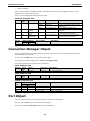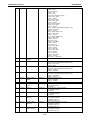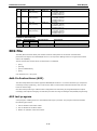
1
Industrial Protocols User’s Guide First Edition, March 2011 www.moxa.com/product © 2011 Moxa Inc. All rights reserved. Reproduction without permission is prohibited. Industrial Protocols User’s Guide The software described in this manual is furnished under a license agreement and may be used only in accordance with the terms of that agreement. Copyright Notice ©2011 Moxa Inc., All rights reserved. Trademarks The MOXA logo is a registered trademark of Moxa Inc. All other trademarks or registered marks in this manual belong to their respective manufacturers. Disclaimer Information in this document is subject to change without notice and does not represent a commitment on the part of Moxa. Moxa provides this document as is, without warranty of any kind, either expressed or implied, including, but not limited to, its particular purpose. Moxa reserves the right to make improvements and/or changes to this manual, or to the products and/or the programs described in this manual, at any time. Information provided in this manual is intended to be accurate and reliable. However, Moxa assumes no responsibility for its use, or for any infringements on the rights of third parties that may result from its use. This product might include unintentional technical or typographical errors. Changes are periodically made to the information herein to correct such errors, and these changes are incorporated into new editions of the publication. Technical Support Contact Information www.moxa.com/support Moxa Americas Toll-free: 1-888-669-2872 Tel: +1-714-528-6777 Fax: +1-714-528-6778 Moxa China (Shanghai office) Toll-free: 800-820-5036 Tel: +86-21-5258-9955 Fax: +86-21-5258-5505 Moxa Europe Tel: +49-89-3 70 03 99-0 Fax: +49-89-3 70 03 99-99 Moxa Asia-Pacific Tel: +886-2-8919-1230 Fax: +886-2-8919-1231 Table of Contents 1. MODBUS/TCP MAP ............................................................................................................................ 1-1 Introduction ....................................................................................................................................... 1-1 Data Format and Function Code ............................................................................................................ 1-1 MODBUS Data Map and Information Interpretation of Moxa Switches ........................................................ 1-1 2. ETHERNET/IP ...................................................................................................................................... 2-1 Introduction ....................................................................................................................................... 2-1 Messaging Types................................................................................................................................. 2-1 Configuring EtherNet/IP on Moxa Switches............................................................................................. 2-1 CIP Objects of EtherNet/IP ................................................................................................................... 2-2 Identity Object ................................................................................................................................... 2-2 TCP/IP Interface Object ....................................................................................................................... 2-3 Ethernet Link Object ........................................................................................................................... 2-4 Assembly Object ................................................................................................................................. 2-7 Message Router Object ........................................................................................................................ 2-7 Connection Manager Object ................................................................................................................. 2-8 Port Object ........................................................................................................................................ 2-8 Moxa Networking Object (Vendor Specific) ............................................................................................. 2-9 EDS File .......................................................................................................................................... 2-11 Add-On Instructions (AOI) .......................................................................................................... 2-11 AOI test program ...................................................................................................................... 2-11 1 1. MODBUS/TCP MAP Introduction MODBUS TCP is a protocol commonly used for the integration of a SCADA system. It is also a vendorneutral communication protocol used to monitor and control industrial automation equipment such as PLCs, sensors, and meters. In order to be fully integrated into industrial systems, Moxa’s switches support Modbus TCP/IP protocol for real-time monitoring in a SCADA system. Data Format and Function Code MODBUS TCP supports different types of data format for reading. The primary four types of them are: Data Access Type Bit access Physical Discrete Inputs Internal Bits or Physical Coils Word access Physical Input Registers (16-bit access) Physical Output Registers Function Code 2 1 Function Name 4 3 Read Input Registers Read Holding Registers Note Read Discrete Inputs Read Coils Moxa Support Moxa switches support Function Code 4 with 16-bit (2-word) data access for read-only information. MODBUS Data Map and Information Interpretation of Moxa Switches The data map addresses of Moxa switches shown in the following table start from MODBUS address 30001 for Function Code 4. For example, the address offset 0x0000 (hex) equals MODBUS address 30001, and the address offset 0x0010 (hex) equals MODBUS address 30017. Note that all the information read from Moxa switches are in hex mode. To interpret the information, refer to the ASCII table for the translation (e.g. 0x4D = ‘M’, 0x6F = ‘o’). Address Offset Data Type 0x0000 0x0001 0x0002 0x0010 1 word 1 word 1 word 20 words 0x0030 20 words Interpretation Description System Information HEX Vendor ID = 0x1393 Unit ID (Ethernet = 1) HEX Product Code = 0x0003 ASCII Vendor Name = “Moxa” Word 0 Hi byte = ‘M’ Word 0 Lo byte = ‘o’ Word 1 Hi byte = ‘x’ Word 1 Lo byte = ‘a’ Word 2 Hi byte = ‘\0’ Word 2 Lo byte = ‘\0’ ASCII Product Name = “EDS-408A” Word 0 Hi byte = ‘E’ Word 0 Lo byte = ‘D’ Word 1 Hi byte = ‘S’ Word 1 Lo byte = ‘-’ Word 2 Hi byte = ‘4’ Industrial Protocols MODBUS/TCP MAP 0x0050 0x0051 1 word 2 words 0x0053 2 words HEX 0x0055 3 words HEX 0x0058 1 word HEX 0x0059 1 word HEX 0x005A 1 word HEX 0x0082 1 word HEX Port Information 0x1000 to 1 word 0x1011 HEX 0x1100 to 0x1111 1 word HEX 0x1200 to 0x1211 1 word HEX 0x1300 to 0x1311 1 word HEX 0x1400 to 0x1413 (Port 1) 20 words ASCII Word 2 Lo byte = ‘0’ Word 3 Hi byte = ‘8’ Word 3 Lo byte = ‘A’ Word 4 Hi byte = ‘\0’ Word 4 Lo byte = ‘\0’ Product Serial Number Firmware Version Word 0 Hi byte = major (A) Word 0 Lo byte = minor (B) Word 1 Hi byte = release (C) Word 1 Lo byte = build (D) Firmware Release Date For example: Word 0 = 0 x 0609 Word 1 = 0 x 0705 Firmware was released on 2007-05-06 at 09 o’clock Ethernet MAC Address Ex: MAC = 00-01-02-03-04-05 Word 0 Hi byte = 0 x 00 Word 0 Lo byte = 0 x 01 Word 1 Hi byte = 0 x 02 Word 1 Lo byte = 0 x 03 Word 2 Hi byte = 0 x 04 Word 2 Lo byte = 0 x 05 Power 1 0x0000: Off 0x0001: On Power 2 0x0000: Off 0x0001: On Fault LED Status 0x0000: No 0x0001: Yes DO1 0x0000: Off 0x0001: On Port 1 to 8 Status 0x0000: Link down 0x0001: Link up 0x0002: Disable 0xFFFF: No port Port 1 to 8 Speed 0x0000: 10M-Half 0x0001: 10M-Full 0x0002: 100M-Half 0x0003: 100M-Full 0xFFFF: No port Port 1 to 8 Flow Ctrl 0x0000:Off 0x0001:On 0xFFFF:No port Port 1 to 8 MDI/MDIX 0x0000: MDI 0x0001: MDIX 0xFFFF: No port Port 1 to 8 Description Port Description = “100TX,RJ45.” Word 0 Hi byte = ‘1’ Word 0 Lo byte = ‘0’ Word 1 Hi byte = ‘0’ Word 1 Lo byte = ‘T’ … Word 4 Hi byte = ‘4’ Word 4 Lo byte = ‘5’ Word 5 Hi byte = ‘.’ Word 5 Lo byte = ‘\0’ 0x1414 to 0x1427 (Port 2) 1-2 Industrial Protocols MODBUS/TCP MAP Packets Information 0x2000 to 2 words 0x2023 HEX 0x2100 to 0x2123 2 words HEX 0x2200 to 0x2223 2 words HEX 0x2300 to 0x2323 2 words HEX Redundancy Information 0x3000 1 word HEX 0x3100 1 word HEX 0x3200 to 0x3211 1 word HEX 0x3300 1 word HEX 0x3301 1 word HEX 0x3302 1 word HEX 0x3303 1 word HEX 0x3304 1 word HEX Port 1 to 8 Tx Packets Ex: port 1 Tx Packet Amount = 44332211 Received MODBUS response: 0x44332211 Word 0 = 4433 Word 1 = 2211 Port 1 to 8 Rx Packets Ex: port 1 Rx Packet Amount = 44332211 Received MODBUS response: 0x44332211 Word 0 = 4433 Word 1 = 2211 port 1 to 8 Tx Error Packets Ex: port 1 Tx Error Packet Amount = 44332211 Received MODBUS response: 0x44332211 Word 0 = 4433 Word 1 = 2211 port 1 to 8 Rx Error Packets Ex: port 1 Rx Error Packet Amount = 44332211 Received MODBUS response: 0x44332211 Word 0 = 4433 Word 1 = 2211 Redundancy Protocol 0x0000: None 0x0001: RSTP 0x0002:Turbo Ring 0x0003:Turbo Ring V2 0x0004:Turbo Chain RSTP Root 0x0000: Not Root 0x0001: Root 0xFFFF: RSTP Not Enable RSTP Port 1 to 8 Status 0x0000: Port Disabled 0x0001: Not RSTP Port 0x0002: Link Down 0x0003: Blocked 0x0004: Learning 0x0005: Forwarding 0xFFFF: RSTP Not Enable TurboRing Master/Slave 0x0000: Slave 0x0001: Master 0xFFFF: Turbo Ring Not Enable TurboRing 1st Port status 0x0000: Port Disabled 0x0001: Not Redundant Port 0x0002: Link Down 0x0003: Blocked 0x0004: Learning 0x0005: Forwarding TurboRing 2nd Port status 0x0000: Port Disabled 0x0001: Not Redundant Port 0x0002: Link Down 0x0003: Blocked 0x0004: Learning 0x0005:Forwarding TurboRing Coupling 0x0000: Off 0x0001: On 0xFFFF: Turbo Ring is Not Enabled TurboRing Coupling Port Status 0x0000: Port Disabled 0x0001: Not Coupling Port 0x0002: Link Down 0x0003: Blocked 0x0005: Forwarding 0xFFFF: Turbo Ring is Not Enabled 1-3 Industrial Protocols MODBUS/TCP MAP 0x3305 1 word HEX 0x3500 1 word HEX 0x3501 1 word HEX 0x3502 1 word HEX 0x3600 1 word HEX 0x3601 1 word HEX 0x3602 1 word HEX 0x3603 1 word HEX 0x3680 1 word HEX 0x3681 1 word HEX TurboRing Coupling Control Port Status 0x0000: Port Disabled 0x0001: Not Coupling Port 0x0002: Link Down 0x0003: Blocked 0x0005: Forwarding 0x0006: Inactive 0x0007:Active 0xFFFF:Turbo Ring is Not Enabled TurboRing V2 Coupling Mode 0x0000: None 0x0001: Dual Homing 0x0002: Coupling Backup 0x0003: Coupling Primary 0xFFFF:Turbo Ring V2 is Not Enabled TurboRing V2 Coupling Port Primary Status (Used in Dual Homing, Coupling Backup, and Coupling Primary) 0x0000:Port Disabled 0x0001: Not Coupling Port 0x0002: Link Down 0x0003: Blocked 0x0004: Learning 0x0005: Forwarding 0xFFFF: Turbo Ring V2 is Not Enabled TurboRing V2 Coupling Port Backup Status (Only using in Dual Homing) 0x0000: Port Disabled 0x0001: Not Coupling Port 0x0002: Link Down 0x0003: Blocked 0x0004: Learning 0x0005: Forwarding 0xFFFF: Turbo Ring V2 Not Enable TurboRing V2 Ring 1 status 0x0000: Healthy 0x0001: Break 0xFFFF:Turbo Ring V2 Not Enable TurboRing V2 Ring 1 Master/Slave 0x0000: Slave 0x0001: Master 0xFFFF: Turbo Ring V2 Ring 1 Not Enable TurboRing V2 Ring 1 1st Port Status 0x0000: Port Disabled 0x0001: Not Redundant Port 0x0002: Link Down 0x0003: Blocked 0x0004:Learning 0x0005:Forwarding 0xFFFF:Turbo Ring V2 Ring 1 is Not Enabled TurboRing V2 Ring 1’s 2nd Port Status 0x0000: Port Disabled 0x0001: Not Redundant Port 0x0002: Link Down 0x0003: Blocked 0x0004: Learning 0x0005: Forwarding 0xFFFF: Turbo Ring V2 Ring 1 is Not Enabled TurboRing V2 Ring 2 Status 0x0000: Healthy 0x0001: Break 0xFFFF: Turbo Ring V2 Ring 2 is Not Enabled TurboRing V2 Ring 2 Master/Slave 0x0000: Slave 0x0001: Master 0xFFFF: Turbo Ring V2 Ring 2 is Not Enabled 1-4 Industrial Protocols MODBUS/TCP MAP 0x3682 1 word HEX 0x3683 1 word HEX 0x3700 1 word HEX 0x3701 1 word HEX 0x3702 1 word HEX TurboRing V2 Ring 2’s 1st Port Status 0x0000: Port Disabled 0x0001: Not Redundant 0x0002: Link Down 0x0003: Blocked 0x0004: Learning 0x0005: Forwarding 0xFFFF: Turbo Ring V2 Ring 2 is Not Enabled TurboRing V2 Ring 2’s 2nd Port Status 0x0000: Port Disabled 0x0001: Not Redundant 0x0002: Link Down 0x0003: Blocked 0x0004: Learning 0x0005: Forwarding 0xFFFF: Turbo Ring V2 Ring 2 is Not Enabled Turbo Chain Switch Roles 0x0000: Head 0x0001: Member 0x0002: Tail 0xFFFF: Turbo Chain is Not Enabled Turbo Chain 1st Port status 0x0000: Link Down 0x0001: Blocking 0x0002: Blocked 0x0003: Forwarding 0xFFFF: Turbo Ring V2 Ring 2 Not Enable Turbo Chain 2nd Port status 0x0000: Link Down 0x0001: Blocking 0x0002: Blocked 0x0003: Forwarding 0xFFFF: Turbo Ring V2 Ring 2 Not Enable 1-5 2 2. EtherNet/IP Introduction EtherNet/IP is an Industrial Ethernet Protocol defined by the ODVA association. The protocol is open to the public and vendors can implement EtherNet/IP into their industrial devices without incurring a license fee. Many vendors have adopted this protocol as the standard communication protocol between devices. For example, Rockwell Automation uses EtherNet/IP as the standard protocol for their Logix controllers over Ethernet networks. To allow complete integration with a Rockwell system, Moxa switches not only provide a full-functioning of industrial network infrastructure, but also enable the SCADA system to monitor the status of the switches as well as that of the PLCs, .making the switches part of a Rockwell system. Messaging Types EtherNet/IP supports two types of communication methods for EtherNet/IP devices: Explicit Messaging and Implicit Messaging. Explicit Messaging is unscheduled and is used for a request/response communication procedure (or client/server procedure). Explicit Messaging uses TCP/IP over Ethernet. Implicit Messaging is scheduled and is used for a producer/consumer communication with UDP over Ethernet. Implicit Messaging is also called I/O Messaging. Configuring EtherNet/IP on Moxa Switches Check the Enable checkbox to enable EtherNet/IP. With EtherNet/IP enabled, IGMP Snooping and IGMP Query functions will be enabled automatically to be properly integrated in Rockwell systems for multicast Implicit (I/O) Messaging. Industrial Protocols EtherNet/IP CIP Objects of EtherNet/IP Several communication objects are defined in CIP (Common Industrial Protocol). Moxa switches support the following objects for PLCs and SCADA systems to monitor: • Identity Object • TCP/IP Interface Object • Ethernet Link Object • Assembly Object • Message Router Object • Connection Manager Object • Port Object • Moxa Networking Object (Vendor Specific) The supported attributes and services of the above objects are introduced in the table below, including the access rules for each attribute. To understand the details of each attribute of the standard objects, refer to the official documents of CIP introduction (Vol. 1) and the EtherNet/IP Adaptation of CIP (Vol. 2). Identity Object The Class code of Identity object is 0x01 (Defined in CIP Vol1, 5-2). There is one instance of this object in our product. It stores the information of the production and the device. The following tables summarize the class attributes and the instance attributes. Class Attribute List Attr ID Name Data Type Description 1 2 Access Rule Get Get Revision Max Instance UINT (16) UINT (16) 3 Get Number of Instances UINT (16) 6 Get Maximum ID Number Class Attributes UINT (16) 7 Get Maximum ID Number Instance Attributes UINT (16) Revision of this object Maximum instance number of an object currently created in this class level of the device Number of object instances currently created in this class level of the device. The attribute ID number of the last class attribute of the class definition implemented in the device The attribute ID number of the last instance attribute of the class definition implemented in the device Instance Attribute List Attr ID 1 2 3 4 Access Rule Get Get Get Get Name (Struct.) Data Type Vendor ID Device Type Product Code Revision Major Minor 5 6 7 Get Get Get Status Serial Number Product Name 15 Get/Set Assigned Name 17 Get/Set Geographic Location Description UINT (16) UINT (16) UINT (16) (Struct.) USINT (8) USINT (8) 991, the vendor ID of Moxa. 0 x 307, “Managed Ethernet Switch”. Please refer to Product Code Table. The version of the Identity object The structure member, major The structure member, minor. WORD (16) UDINT (32) SHORT_ STRING STRINGI Not used The serial number of each device The product name in human-readable format The assigned switch name For example: “Managed Redundant Switch xxxxx”. (xxxxx is series number.) The assigned switch location The default string is “Switch Location”. STRINGI 2-2 Industrial Protocols EtherNet/IP The Identity Object Instance supports the following CIP Common services: Common Service List Service Code 0x01 0x0E 0X10 Implementation Class Instance Service Name Description Get_Attributes_All Get_Attribute_Single Set_Attribute_Single Returns the contents of all attributes of the class Used to read an object instance attribute. Used to write an object instance attribute Product Code Table Product Code 0x0001 0x0002 0x0003 Model Name n/a n/a EDS-726 Product Code 0x0012 0x0013 0x0014 0x0004 0x0005 0x0006 0x0007 0x0008 0x0009 0x000A 0x000B 0x000C 0x000D 0x000E 0x000F 0x0010 0x0011 n/a EDS-518A EDS-405A EDS-408A EDS-505A EDS-508A EDS-510A EDS-516A EDS-728 PT-7728 EDS-828 PT-7828 PT-7710 IKS-6726 or PT7728S_old 0x0015 0x0016 0x0017 0x0018 0x0019 0x001A 0x001B 0x001C 0x001D 0x001E 0x001F 0x0020 0x0021 0x0022 Model Name EDS-G509 EDS-P510 EDS-516A-MMM12 IKS6526SB EDS-608 IKS-6726-PoE EDS-611 EDS-616 EDS-619 TN-5518 TN-5516 TN-5510 TN-5508 EOM-104 PT-G7509 TN-5518-PoE TN-5516-PoE Product Code 0x0023 0x0024 0x0025 Model Name TN-5510-PoE TN-5508-PoE n/a 0x0026 0x0027 0x0028 0x0029 0x002A 0x002B 0x002C 0x002D 0x002E 0x002F 0x0030 0x0031 0x0032 0x0033 IKS-6524 n/a n/a EDS-P506A PT-7728-PTP PT-510 PT-508 IKS-G6848 IKS-G6852 IKS-G6724 IKS-G6728 IKS-G6824 IKSG6828 n/a TCP/IP Interface Object The Class code of TCP/IP Interface object is 0xf5 (Defined in CIP Vol2, 5-3). There is one instance of this object. The following tables summarize the attributes of this object. Class Attribute List Attr ID Name Data Type Description 1 2 Access Rule Get Get Revision Max Instance UINT (16) UINT (16) 3 Get Number of Instances UINT (16) 6 Get Maximum ID Number Class Attributes UINT (16) 7 Get Maximum ID Number Instance Attributes UINT (16) Revision of this object. Maximum instance number of an object currently created in this class level of the device Number of object instances currently created at this class level of the device The attribute ID number of the last class attribute of the class definition implemented in the device The attribute ID number of the last instance attribute of the class definition implemented in the device Instance Attribute List Attr ID 1 Access Rule Get Name (Struct.) Status 2-3 Data Type Description DWORD (32) Interface status 0 = The Interface Configuration attribute has not been configured. 1 = The Interface Configuration attribute contains valid configuration obtained from BOOTP, DHCP or nonvolatile storage. *2 = The Interface Configuration attribute contains valid configuration, obtained from Industrial Protocols EtherNet/IP 2 Get Configuration Capability DWORD (32) 3 Get/Set Configuration Control DWORD (32) 4 Get Physical Link Object (Struct.) hardware settings (e.g.: pushwheel, thumbwheel, etc.) Interface capability flags Bit map of capability flags: Bit 0: BOOTP Client Bit 1: DNS Client Bit 2: DHCP Client Bit 3: DHCP-DNS Update Bit 4: Configuration Settable Interface control flags Bit map of control flags: Bit 0 to 3: Startup Configuration 0 = The device shall use the interface configuration values previously stored (for example, in non-volatile memory or via hardware witches). 1 = The device shall obtain its interface configuration values via BOOTP. 2 = The device shall obtain its interface configuration values via DHCP upon start-up. 3 to15 = Reserved. *Bit 4: DNS Enable If True, the device shall resolve host names by querying a DNS server. Path to physical link object Path Size UINT (16) Size of Path Path Padded EPATH Logical segments identifying the physical link object 5 6 Get/Set Get/Set Interface Configuration (Struct.) IP Address UDINT (32) TCP/IP network interface configuration The device’s IP address Network Mask Gateway Address Name Server Name Server2 Domain Name UDINT (32) The device’s network mask UDINT (32) Default gateway address UDINT (32) UDINT (32) Primary name server Secondary name server STRING Default domain name STRING Host name Host Name The TCP/IP Object Instance supports the following CIP Common services: Common Service List Service Code 0 x 01 0 x 0E 0 x 10 Implementation Class Instance Service Name Description Get_Attributes_All Get_Attribute_Single Set_Attribute_Single Returns the contents of all attributes of the class Used to read an object instance attribute Used to modify an object instance attribute Ethernet Link Object The Class code of Ethernet Link object is 0xf6 (Defined in CIP Vol2, 5-4). For each switch port, there is an instance of this class. 2-4 Industrial Protocols EtherNet/IP The following table shows the mapping of instance number and the switch port number. Instance Number 0 1 2 3 – Mapping to Ethernet Link class 1st switch port 2nd switch port 3rd switch port – The following tables summarize the attributes of the Ethernet Link object. There are some vendor specific attributes in the table (Starting from attribute Id 100). Class Attribute List Attr ID Name Data Type Description 1 2 Access Rule Get Get Revision Max Instance UINT (16) UINT (16) 3 Get Number of Instances UINT (16) 6 Get Maximum ID Number Class Attributes UINT (16) 7 Get Maximum ID Number Instance Attributes UINT (16) 100 Get Moxa-specific Revision UINT (16) Revision of this object Maximum instance number of an object currently created in this class level of the device Number of object instances currently created in this class level of the device The attribute ID number of the last class attribute of the class definition implemented in the device The attribute ID number of the last instance attribute of the class definition implemented in the device Revision of Moxa specific attributes and services Instance attribute list Attr ID 1 Access Rule Get Name 2 3 4 5 Data Type Description Interface Speed UDINT (32) Get Get Interface Flags Physical Address Get Interface Counters DWORD (32) ARRAY of 6 USINT(8) (Struct.) Interface speed currently in use (Speed in Mbps, e.g., 0, 10, 100, 1000, etc.) Refer to the Interface Flags table. MAC layer address (The System MAC address). Counters relevant to the receipt of packets. Octets received on the interface. Get (Struct.) In Octets UDINT (32) In Ucast Packets In NUcast Packets In Discards UDINT (32) In Errors UDINT (32) *In Unknown Protos Out Octets UDINT (32) Out Ucast Packets Out NUcast Packets Out Discards UDINT (32) Out Errors UDINT (32) Alignment Errors UDINT (32) FCS Errors UDINT (32) Media Counters UDINT (32) UDINT (32) UDINT (32) UDINT (32) UDINT (32) Unicast packets received on the interface. Non-unicast packets received on the interface. Inbound packets received on the interface but are discarded. Inbound packets that contain Errors (does not include In Discards). Inbound packets with unknown protocols (not support). Octets sent on the interface. Unicast packets sent on the interface. Non-unicast packets sent on the interface. Discarded outbound packets. Outbound packets that contain errors. (Struct.) 2-5 Received frames that are not an integral number of octets in length. Received frames that do not pass the FCS check. Industrial Protocols EtherNet/IP Single Collisions UDINT (32) Multiple Collisions UDINT (32) SQE Test Errors UDINT (32) Deferred Transmissions UDINT (32) Late Collisions UDINT (32) Excessive Collisions UDINT (32) MAC Transmit Errors UDINT (32) Carrier Sense Errors UDINT (32) Frame Too Long UDINT (32) MAC Receive Errors 6 Get/Set Interface Control (Struct.) Control Bits 100 Get 101 Get 102 Get/Set 103 Get 104 Get/Set 105 Get/Set 106 Get/Set 107 Get/Set Interface Port Index Interface Port Description Broadcast Storm Protection UDINT (32) WORD (16) Forced Interface UINT (16) Speed UDINT (32) Interface Utilization Utilization Alarm Upper Threshold Utilization Alarm Lower Threshold Port Link Alarm Frames for which transmission fails due to an internal MAC sublayer transmit error. Times that the carrier sense condition was lost or never asserted when attempting to transmit a frame. Received frames that exceed the maximum permitted frame size. Frames for which reception on an interface fails due to an internal MAC sublayer receive error. Configuration for physical interface. Bit 0: Auto-Negotiate Value 0: Force Value 1: Auto-Nego Bit 1: Half/Full Duplex Value 0: half duplex Value 1: full duplex Bit 2 to 15: Reserved, all zero Speed at which the interface shall be forced to operate. Port index. Port description. USINT (8) Value 0: Disabled Broadcast Storm Protection. Value 1: Enable Broadcast Storm Protection. (not all production support) RX interface utilization in percentage RX interface utilization upper limit in percentage USINT (8) USINT (8) RX interface utilization lower limit in percentage(not support) USINT (8) Value Value Value Value Value Value Value Value USINT (8) 2-6 Frames for which first transmission attempt is delayed because the medium is busy. Number of times a collision is detected later than 512 bit times into the transmission of a packet. Frames for which transmission fails due to excessive collisions. STRING USINT (8) Port TrafficOverload Alarm Successfully transmitted frames which experienced exactly one collision. Successfully transmitted frames which experienced more than one collision. Number of times the SQE test error message is generated. 0: 1: 2: 3: 4: 0: 1: 2: Ignore On (Relay 1) On (Relay 2) Off (Relay 1) Off (Relay 2) Disable Enable(Relay 1) Enable(Relay 2) Industrial Protocols EtherNet/IP Interface Flags Bit(s) 0 Called Link Status 1 Half/Full Duplex 2 to 32 Reserved Definition 0 indicates an inactive link; 1 indicates an active link. 0 indicates half duplex; 1 indicates full duplex. Not used The Ethernet Link Object Instance supports the following CIP Common services: Common Service List Service Code 0x0E 0x10 Implementation Class Instance Service Name Description Get_Attribute_Single Set_Attribute_Single Used to read an object instance attribute Used to modify an object instance attribute Assembly Object The Moxa switch support static assembly object for CIP I/O messaging. The Class code is 0x04 (Defined in CIP Vol 1, 5-5). There are three instances of this object as the following. Instance Number Size (byte) Input 2 [TBD] Output 1 [TBD] Configuration 3 0 The Input means the data is produced by switch which includes the information and status report to the originator for monitoring. The Output means the data is generated by the originator (remote host) and is consumed by switch. Class Attribute List Attr ID 1 Access Rule Get Name Revision Data Type UINT (16) Description Revision of this object Instance Attribute List Attr ID 3 4 Access Rule Get/Set Get Name Data Size (Struct.) Data Type Array of BYTE UINT (16) Description The implicit messaging content Number of bytes in Attr. 3 Common Service List Service Code 0x0E 0x10 Implementation Class Instance Service Name Description Get_Attribute_Single Set_Attribute_Single Used to read an object instance attribute Used to modify an object instance attribute For the definition of the I/O messaging, see the following table for details. I/O Messaging Content Direction Input Output I/O data Switch Fault Status Port Exist Port Link Status Port Enable Size UDINT (32) ULINT (64) ULINT (64) ULINT (64) Value & Description Please refer to Moxa Networking Please refer to Moxa Networking Please refer to Moxa Networking Please refer to Moxa Networking Object Object Object Object Attr Attr Attr Attr ID ID ID ID 2. 4. 6. 5. Message Router Object The object within a node that distributes messaging requests to the appropriate application objects. The supported messaging connections are as the following: • Explicit Messaging • Unconnected Messaging 2-7 Industrial Protocols • EtherNet/IP Implicit messaging When using the UCMM to establish an explicit messaging connection, the target application object is the Message Router object (Class Code 2). There is no class attribute for Message Router object. Instance Attribute List Attr ID 1 Access Rule Get Name (Struct.) Data Type Description Number (Struct.) UINT (16) A list of supported objects Number of supported classes in the classes array List of supported class codes Maximum number of connections supported Number of connections currently used by system components A list of the connection IDs of the currently active connections Object_list Classes 2 Get 3 Get 4 Get Array of UINT (16) UINT (16) Number Available Number Active Active Connections UINT (16) Array of UINT (16) Common Service List Service Code Implementation Class 0x0E Instance Service Name Description Get_Attribute_Single Used to read an object instance attribute Connection Manager Object The Connection Manager Class allocates and manages the internal resources associated with both I/O and Explicit Messaging connections. The class code is 0x06. There is one instance of this object. The supported connection trigger type is cyclic and change of state. The instance attribute list is introduced as the following. Class Attribute List Attr ID 1 Access Rule Get Name Data Type Description Revision UINT (16) Revision of this object Name Data Type Description Open Requests UINT(16) Number of Forward Open service requests received Class Attribute List Attr ID 1 Access Rule Get/Set Common Service List Service Code 0x0e 0x10 Implementation Class Instance 0x4E 0x54 Service Name Description Get_Attribute_Single Set_Attribute_Single Returns the contents of the specified attribute Used to modify an object instance attribute Forward_Close Forward_Open Closes a connection Opens a connection Port Object The port object represents the underlying interface of CIP which is EtherNet/IP. The class code is 0xf4. There is one instance of this object. The instance attribute “Port Type” identifies the CIP adaptation. 2-8 Industrial Protocols EtherNet/IP Class Attribute List Attr ID 1 2 Access Rule Get Get Name 3 Get 8 Get 9 Get (Struct.) Data Type Description Revision Max Instance UINT (16) UINT (16) Number of Instances Entry Port UINT (16) Revision of this object Maximum instance number of an object currently created in this class level of the device Number of object instances currently created at this class level of the device. The attribute ID number of the last class attribute of the class definition implemented in the device Port Instance Info (Array of Struct.) UINT (16) UINT (16) UINT (16) Port Type Port Number Enumerates the type of port CIP port number associated with this port Instance Attribute List Attr ID 1 Access Rule Get Name 2 3 Get Get Port Number Link Object (Struct.) Port Type Get Port Name 5 Get Port Type Name 6 Get/Set Port Description 7 Get Node Address 9 Get Port Key Description UINT (16) Enumerates the type of port. 4 = EtherNet/IP. CIP port number associated with this port. UINT (16) (Struct.) Path Length UINT (16) Number of 16 bit words in the following path. Padded Logical path segments that identify the EPATH object for this port. SHORT_STR String which names the physical network ING port. The maximum number of characters in the string is 64. SHORT_STR String which names the port type. The ING maximum number of characters in the string is 64. SHORT_STR String which describes the port. The ING maximum number of characters in the string is 64. Padded Node number of this device on port. The EPATH range within this data type is restricted to a Port Segment. Packed Electronic key of network/chassis this port is EPATH attached to. This attribute shall be limited to format 4 of the Logical Electronic Key segment. Link Path 4 Data Type Common Service List Service Code 0x0E 0x10 Implementation Class Instance Service Name Description Get_Attribute_Single Set_Attribute_Single Used to read an object instance attribute Used to modify an object instance attribute Moxa Networking Object (Vendor Specific) The Moxa Networking object includes system information and status. It can also be used to do the device diagnostic & configuration through explicit messaging. The class code is 0x404. Class Attribute List Attr ID Access Rule 1 Get Name Revision Data Type UINT (16) Description Revision of this object Instance Attribute List Attr ID 1 2 Access Rule Get Get Name Data Type Description Firmware Version System Fault Status UDINT (32) UDINT (32) Switch firmware version Switch fault status Bit 0: Reserved 2-9 Industrial Protocols 3 Get 4 EtherNet/IP Get Switch Port Number Port Exist USINT (8) ULINT (64) 5 Get/Set Port Enable ULINT (64) 6 Get Port Link Status ULINT (64) 7 Get/Set IGMP Snooping Enable USINT (8) 8 9 Get/Set Get/Set Query Interval IGMP Enhanced Mode UDINT (32) USINT (8) 14 Get/Set Relay 1 USINT (8) 15 Get/Set Relay 2 USINT (8) 16 Get/Set Power 1 Relay Warning USINT (8) 17 Get/Set Power 2 Relay Warning USINT (8) 18 Get/Set DI 1 (0ff) Relay Warning USINT (8) 2-10 Value 0: Ok Value 1: Fail Bit 1: Reserved Value 0: Ok Value 1: Fail Bit 2: Port utilization alarm Value 0: No alarm Value 1: alarm Bit 3: Port link up Value 0: No alarm Value 1: Alarm Bit 4: Port link down Value 0: No alarm Value 1: Alarm Bit 5: Turbo ring break(Ring Master only) Value 0: No alarm Value 1: Alarm Bit 6: Power Input 1 fail Value 0: No alarm Value 1: Alarm Bit 7: Power Input 2 fail Value 0: No alarm Value 1: Alarm Bit 8:DI 1(off) Value 0: No alarm Value 1: Alarm Bit 9: DI 1(on) Value 0: No alarm Value 1: Alarm Bit 10: DI 2(off) Value 0: No alarm Value 1: Alarm Bit 11: DI 2(on) Value 0: No alarm Value 1: Alarm Bit 12 to 31: Reserved Switch max port number switch per port exist Bit mask, the LSB indicates the first port. Value 0: Not exist Value 1: Exist Switch per port enable Bit mask, the LSB indicates the first port. Value 0: Enable Value 1: Disable Switch per port link status Bit mask, the LSB indicates the first port. Value 0: Link down Value 1: Link up IGMP snooping enable: Value 0: Disable Value 1: Enable Query interval range from 20 to 600 secs IGMP enhanced mode 0: Enable(default) 1: Disable Override relay warning setting 0: Disable(default) 1: Enable Override relay warning setting 0: Disable (default) 1: Enable Power input 1 failure (on->off) 0: Disable (default) 1: Enable (relay 1) 2: Enable (relay 2) Power input 2 failure (on->off) 0: Disable (default) 1: Enable (relay 1) 2: Enable (relay 2) DI 1 (0ff) 0: Disable (default) 1: Enable (relay 1) Industrial Protocols EtherNet/IP 19 Get/Set DI 1 (on) Relay Warning USINT (8) 20 Get/Set DI 2 (0ff) Relay Warning USINT (8) 21 Get/Set DI 2 (on) Relay Warning USINT (8) 22 Get/Set Turbo Ring Break Relay Warning USINT (8) 23 Get CPU Usage USINT (8) 2: Enable (relay 2) DI 1 (0n) 0: Disable (default) 1: Enable (relay 1) 2: Enable (relay 2) DI 2 (0ff) 0: Disable (default) 1: Enable (relay 1) 2: Enable (relay 2) DI 2 (0n) 0: Disable (default) 1: Enable (relay 1) 2: Enable (relay 2) Turbo ring break (Ring Master only) 0: Disable (default) 1: Enable (relay 1) 2: Enable (relay 2) Percent of usage (0 to100) Common Service List Service Code 0x0E 0x10 Implementation Class Instance Service Name Description Get_Attribute_Single Set_Attribute_Single Used to read an object instance attribute Used to modify an object instance attribute EDS File The EDS (Electronic Data Sheet) file contains electronic descriptions of all relevant communication parameters and objects of an EtherNet/IP device. It is required for RSLogix 5000 to recognize Moxa switch and its CIP capability. The list includes the sections which are described in our EDS file. • [File] • [Device] • [Device Classification] • [Port] Icon should be 32 * 32 in pixel. Add-On Instructions (AOI) The AOI encapsulates Moxa switch supported EtherNet/IP functions in a common interface logic component. In RSLogix 5000 programming, users could use the AOI to communicate with Moxa switches and need not know the internal logic. Our AOI would provide logic of Moxa switch configuration and monitoring by using EtherNet/IP in explicit messaging and implicit messaging. The AOI also provides some tags for RSLogix 5000/SCADA programming. AOI test program A test program of RSLogix 5000 to demonstrate AOI usage is provided. This program would demonstrate the following procedures. 1. Get an attribute of the Moxa switch. 2. Set an attribute of the Moxa switch. 3. Monitor an I/O data of the Moxa switch. 2-11