1
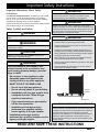
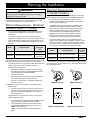
Installation Instructions
Discover y ® Range
Models: DYRP36DS, DYRP36D-C-S, DYRP48DS, DYRP48D-C-S
THIS APPLIANCE HAS BEEN TESTED IN ACCORDANCE WITH THE LATEST
EDITIONS OF ANSI Z21.1, UL858 AND UL60730-1, STANDARDS FOR HOUSEHOLD
APPLIANCES.
Part No. 108106 Rev. B
Table of Contents
Customer Service Information.....................................................II
Important Safety Instructions...................................................... 1
General Safety Precautions......................................................... 2
Planning the Installation............................................................... 3
Electrical Requirements...............................................................3
Product Dimensions.....................................................................4
Gas Supply Requirements........................................................... 4
Cabinet Layout.............................................................................6
Installation Instructions................................................................7
Preparing for Installation.............................................................. 7
Electrical Connection.................................................................10
Gas Connection.........................................................................15
Final Installation.........................................................................16
Installing the Burner Knobs....................................................... 17
Cooktop Assembly.....................................................................18
Verifying Proper Operation........................................................ 19
Installation Checklist..................................................................19
IMPORTANT:
•
Installer: In the interest of safety and to minimize problems, read these installation instructions completely and carefully before you
begin the installation process. Leave these installation instructions with the customer.
•
Customer: Keep these installation instructions for future reference and the local building inspector’s use.
Customer Service Information
If you have questions or problems with installation, contact your
Dacor dealer or the Dacor Customer Service Team. For repairs
to Dacor appliances under warranty call the Dacor Distinctive
Service line. Whenever you call, have the model and serial
number of the appliance ready. The serial number and rating
labels are inside the grate, inside the door.
Dacor Customer Service Team
Phone: (800) 793-0093 ex. 2813 (U.S.A. and Canada)
Monday — Friday 6:00 a.m. to 5:00 p.m. Pacific Time
Web site: www.dacor.com
Dacor Distinctive Service (for repairs under warranty only)
Phone: (800) 793-0093 ex. 2822 (U.S.A. and Canada)
Monday — Friday 6:00 a.m. to 5:00 p.m. Pacific Time
Model Identification
DYRP36D-C-S/NG/H
SIZE (width in inches)
CORD OPTION
-C- = Appliance cord installed*
No Character = Power cord not included
GAS TYPE
NG = Natural Gas
LP = Liquid Petroleum (Propane)
Model and serial
number label located
inside grill
ALTITUDE
H = Equipped for high altitude operation,
4000 ft. (1219 m) and up
No Character = Equipped for low altitude operation
* Mandatory configuration for freestanding units
installed in Canada.
Model and Serial Number Location
All specifications subject to change without notice.
No liability is assumed by Dacor® for changes to specifications.
© 2014 Dacor, all rights reserved.
Important Safety Instructions
Important Information About Safety
Instructions
The Important Safety Instructions and warnings in this manual
are not meant to cover all possible problems and conditions
that can occur. Use common sense and caution when installing,
maintaining or operating this or any other appliance.
Always contact the Dacor Customer Service Team about problems
and conditions that you do not understand.
Safety Symbols and Labels
DANGER
WARNING
WARNING – NEVER use this appliance as a space heater
to heat or warm the room. Doing so may result in carbon
monoxide poisoning and overheating of the appliance.
WARNING
NEVER cover any slots, holes or passages on the inside or
outside of the range or cover an entire rack with materials such
as aluminum foil. Doing so blocks air flow through the oven and
may cause carbon monoxide poisoning. Aluminum foil linings
may also trap heat, causing a fire hazard.
Immediate hazards that WILL result in severe personal injury or
death.
WARNING
Hazards or unsafe practices that COULD result in severe
personal injury or death.
CAUTION
Hazards or unsafe practices that COULD result in minor
personal injury or property damage.
WARNING
If the information in this manual is not
followed exactly, a fire or explosion may
result causing property damage, personal
injury or death.
-- Do not store or use gasoline or other
flammable vapors and liquids in the
vicinity of this or any other appliance.
WARNING
Tip-over hazard:
•
A child or adult can tip the range and be killed.
•
Attach the anti-tip bracket to the floor as directed in these
installation instructions.
•
Engage the anti-tip bracket by sliding the anti-tip foot on
the range into it according to these installation instructions.
Using a flashlight, be sure that the anti-tip bracket engages
the range’s anti-tip foot as shown below.
•
After moving the range, be sure to re-engage the anti-tip
foot into the anti-tip bracket as shown below.
•
See the anti-tip bracket installation instructions in this guide
for further details.
•
Failure to follow these instructions can result in death or
serious burns to children or adults.
-- WHAT TO DO IF YOU SMELL GAS
• Do not try to light any appliance.
• Do not use any phone in your building.
• Immediately call your gas supplier from
a neighbor’s phone. Follow the gas
supplier’s instructions.
• If you cannot reach your gas supplier,
call the fire department.
• Installation and service must be
performed by a qualified installer,
service agency or the gas supplier.
-- Installation and service must be
performed by a qualified installer, service
agency or the gas supplier.
Anti-tip
bracket
Anti-tip foot
CALIFORNIA PROPOSITION 65 WARNING
The burning of gas cooking fuel generates some by-products
that are on the list of substances which are known by the State
of California to cause cancer or reproductive harm. California
law requires businesses to warn customers of potential
exposure to such substances. To minimize exposure to these
substances, always operate this unit according to the use
and care manual, ensuring you provide good ventilation when
cooking with gas.
READ AND SAVE THESE INSTRUCTIONS
1
Important Safety Instructions
WARNING
•
Read the accompanying use and care manual before
operating this appliance.
•
Clean the cooktop thoroughly before operating it for the first
time.
•
Keep packaging materials away from children. Plastic
sheets and bags can cause suffocation.
•
•
If you receive a damaged product, immediately contact
your dealer or builder. Do not install or use a damaged
appliance.
Keep flammable items, such as paper, cardboard, plastic
and cloth away from the burners and other hot surfaces.
Do not place such items in the oven(s). Do not allow pot
holders to touch hot surfaces or gas burners.
•
Do not wear loose or hanging apparel while using the
range. Do not allow clothing to come into contact with the
interior of the oven(s) or the cooktop and surrounding areas
during and immediately after use.
•
To avoid a fire hazard, do not hang flammable or heat
sensitive objects over the range. If the range is near a
window, do not use long curtains as window treatment.
The curtains could blow over the cooktop and create a fire
hazard.
•
Do not use the oven(s) for storage.
•
Do not touch the outside surfaces of the range during the
self-clean cycle. They will be hot. Venting from the oven
may cause the cooktop and backguard to become hot.
•
Make sure that all the cooktop parts are dry before lighting
a burner.
•
Turn the knobs to the “OFF” position prior to removing them
from the valve stems.
•
The cooktop should never be operated without the knobs
and trim rings in place.
•
For your safety, do not use the oven to cook without the
convection filter installed. When the filter is not installed, the
spinning fan blades at the back of the oven are exposed.
•
Non-stick coatings, when heated, can be harmful to birds.
Remove birds to a separate, well-ventilated room during
cooking.
•
To prevent damage, remove the meat probe from the
oven(s) when it is not being used.
•
2
WARNING
This range must be properly installed and grounded by a
qualified installer according to these installation instructions
prior to use. The installer should show the customer the
location of the gas shut off valve and the fuse or junction
box so that they know where and how to turn off the gas
supply and power to the range.
•
This appliance is not designed for installation in a mobile
home or recreational vehicle.
•
Do not use this appliance in combination with a surface
(countertop) ventilation system, air curtain or other type of
range hood that directs airflow in a downward direction.
•
Do not install, repair or replace any part of the range unless
specifically recommended in the literature accompanying
it. A qualified service technician should perform all other
service.
•
Do not connect this range to the gas supply without the
supplied gas pressure regulator installed.
•
Before performing any type of service or installation, make
sure the gas supply and power to the range are turned off.
•
NEVER block or cover any slots, holes or passages
anywhere inside the oven or on the outside of the range or
cover an oven rack with materials such as aluminum foil.
Doing so blocks airflow through the oven and cooktop and
may cause carbon monoxide poisoning or fire. See the
Getting to Know Your Range section of the use and care
manual for the location of the various air holes (slots).
•
Only use the range for cooking tasks expected of a home
appliance as outlined in the literature accompanying it. This
range is not intended for commercial use.
•
•
DO NOT TOUCH THE SURFACES OF THE OVEN[S] OR
COOKTOP DURING OR IMMEDIATELY AFTER USE.
Do not line the oven(s) with aluminum foil or other
materials. These items can melt or burn up during selfcleaning and cause permanent damage to the appliance.
•
•
To avoid the possibility of fire, never leave this appliance
unattended when the cooktop is in use.
•
Do not climb on any part of the appliance.
Do not leave metal objects, such as aluminum foil, the meat
probe, cookie sheets, etc. on the bottom of the oven(s).
Objects left on the bottom of the oven could damage the
bake element. In addition, the objects themselves could be
damaged.
•
Do not leave children or pets alone or unattended in the
area around the range. Do not allow children to play with
the controls, pull on the handle(s), or touch other parts of
the range.
•
•
Do not store items of interest to children on top of or
above the range. Children could be burned or injured while
climbing on the appliance.
On some ovens, the bake and broil elements are behind
glass panels on the floor and ceiling of the oven chamber.
Do not cover these glass panels with cookie sheets,
aluminum foil, pots, pans, etc. Covering them could cause
the heating elements to over-heat, damaging the oven.
•
Do not attempt to use this appliance in the event of a power
failure.
Planning the Installation
WARNING
IMPORTANT: Observe all governing codes and ordinances
during planning and installation. Contact your local building
department for further information.
The appliance installation must be electrically grounded in
accordance with local codes or, in the absence of local codes,
with the National Electrical Code, ANSI/ NFPA 70:
Electrical Requirements - All Model
Numbers Except -C Models)
•
It is the owner’s responsibility to ensure that the electrical
connection of this appliance is performed by a licensed
electrician.
•
The correct voltage, frequency and amperage must be
supplied to the appliance from a separate, grounded, circuit
that is protected by a properly sized circuit breaker or time
delay fuse. If a fuse is utilized, fuse both sides of the line (L1
and L2).
Model
Circuit Required
Total
Connected
Load
DYRP36DS
240 Vac*, 60 Hz, 30 Amp.
5.75 kW
(24.0 Amp.)
DYRP48DS
240 Vac*, 60 Hz, 50 Amp.
10.1 kW
(41.9 Amp.)
* 4-wire, two 120 Vac hot (L1 and L2), one neutral, one ground
The ratings above are for reference only. Refer to the range data
label for exact specifications (see inside cover for location).
• The wiring needs to be long enough to allow the range to be
pulled out for service, while remaining connected.
• The wiring to the range must:
◊ Meet NEMA standards and have a minimum rating of
250 Volts @ 30 Amps for model DYRP36DS and 250
Volts @ 50 amps for model DYRP48DS
◊ Include a strain relief
◊ Be terminated by tinned leads, closed loop terminals or
open ended spade lugs with upturned ends
◊ Connect to a junction box or receptacle installed by a
licensed electrician
The appliance may be connected one of the following ways:
•
Using conduit:
◊ A 4-wire conduit connected to a 4-wire junction box, or
◊ A 3-wire conduit (where local code permits, not for use
with new branch circuit installations) connected to a
3-wire junction box.
Suggested wiring color code: black, white, red and green.
•
Using an appliance cord:
◊
◊
◊
A 4-wire appliance cord equipped with a NEMA 14-50P
plug connected to a NEMA 14-50R receptacle, or
A 3-wire appliance cord (where local code permits)
equipped with a NEMA 10-50P plug connected to a
NEMA 10-50R receptacle
Appliance cord plug must be UL listed type SRD or
SRDT.
Electrical Requirements
-C Model Numbers
Range models DYRP36D-C-S and DYRP48D-C-S come with a
factory installed 4-wire appliance cord with NEMA 14-50P plug.
•
For freestanding ranges installed in Canada, a factory
installed 4-wire appliance cord with NEMA 14-50P plug is
required, without modification.
•
The NEMA 14-50P plug is designed to plug directly into
a NEMA 14-50R electrical receptacle. It is the owner’s
responsibility to ensure that the required 4-wire electrical
outlet compatible with the power cord is installed by a
licensed electrician as specified below prior to range
installation. The electrical outlet installation, including
minimum supply wire size and grounding, must be in
accordance with all governing codes and ordinances.
•
The correct voltage, frequency and amperage must be
supplied to the appliance from a separate, grounded, circuit
that is protected by a properly sized circuit breaker or time
delay fuse. If a fuse is utilized, fuse both sides of the line (L1
and L2). Refer to the ratings on the range rating label.
Model
Circuit Required
Total
Connected
Load
DYRP36D-C-S
240 Vac*, 60 Hz, 30 Amp.
5.75 kW
(24.0 Amp.)
DYRP48D-C-S
240 Vac*, 60 Hz, 50 Amp.
10.1 kW
(41.9 Amp.)
* Two 120 Vac hot (L1 and L2), one neutral (N1) and one ground.
The ratings above are for reference only - refer to the range rating
label (see inside cover).
NEMA 14-50P Plug
NEMA 14-50R Receptacle
NEMA 10-50P Plug
NEMA 10-50R Receptacle
3
Planning the Installation
Gas Supply Requirements
•
GAS SUPPLY PRESSURE REQUIREMENTS*
(All units)
The installation of this appliance must conform with local
codes or, in the absence of local codes, with the National
Fuel Gas Code, ANSI Z223.1/NFPA 54.
•
Be certain that the appliance being installed is correct for
the gas service provided (natural gas or LP gas). Also, if
operating the range at an altitude above 4000 ft. (1219 m)
make sure it is equipped for high altitude operation. Refer
to the range rating label and the table on the inside cover to
determine the correct model.
•
See the table to the right for gas supply pressure
requirements.
•
The regulator inlet accommodates a 3/4” gas line. The range
ships with a 1/2” to 3/4” adapter connected to the regulator.
Gas
Inlet
Gas Type
Minimum
Manifold Pressure
Minimum Gas
Supply Pressure**
Natural Gas
5” Water Column
6” Water Column
Liquid Propane (LP)
10” Water Column
11” Water Column
* The gas supply pressure for testing the regulator setting shall
be at least 1 inch water column (249 Pa) above the specified
manifold pressure.
** Maximum gas supply pressure for all models: 1/2 psi.
The ratings above are for reference only. Refer to the range rating
label for exact specifications (see page II for location).
Shown with electrical
access cover removed
Back of range
B
D
A
C
E - Electrical wiring
access hole in bottom
GAS - ELECTRICAL ACCESS DIMENSIONS
1
2
Model
A
B1
C
D1
E2
DYRP36D[-C-]S
6 3/4”
(17.1 cm)
27”
(68.6 cm)
12”
(30.5 cm)
6 3/4”
(17.1 cm)
7/8” dia.
(2.2 cm)
DYRP48D[-C-]S
4 1/4”
(10.8 cm)
27”
(68.6 cm)
9”
(22.9 cm)
6 3/4”
(17.1 cm)
7/8” dia.
(2.2 cm)
Measurement with appliance legs adjusted to lowest height.
The hole size for the electrical wiring may be increased to 1 1/8” (2.9 cm) by
removing the conduit bracket in the bottom of the range electrical box. Model
numbers ending with -C come from the factory pre-wired with an appliance cord and
no adapter (E = 1 1/8”).
4
Planning the Installation
Product Dimensions
Product tolerances: ±1/16” (±1.6 mm)
Front of open door
Front of handle
Front edge of bull nose
Front panel
Rear of front panel/oven door
48” (121.9 cm)
28 1/2” (72.4 cm)
26 7/8” (68.3 cm)
26” (66.0 cm)
24” (61.0 cm)
1 1/4”
(3.2 cm)
X*
* The optional backguard is
available in two heights; 3
and 9 inches high.
1 1/16” (2.7 cm) to cooking
surface (top of grates) from
top of trim
36 3/16”
(91.9 cm)
to
37 1/2”
(95.3 cm)
Finished side
panel
Width: DYRP36D[-C-]S - 35 7/8” (91.1 cm)
DYRP48D[-C-]S - 47 7/8” (121.6 cm)
24” (61.0 cm)
29 7/8” (75.9 cm)***
Back of
control
panel
Cabinet face
Countertop*
Cabinet face**
Countertop height:
36 3/16" (91.9 cm) min.
37 1/2” (95.3 cm) max.
DYRP36DS or
DYRP48DS Range
3/8” min. (1.0 cm)
flat countertop
overhang required
behind cutout
Stiffener
3/8” min. (1.0 cm)
space behind
doendraft vent
chassis to clear
stiffener
ERV36-ER or
ERV48-ER
downdraft vent
View of Range Installed
(Side View)
* IMPORTANT: See “CUTOUT WITH OPTIONAL ERV DOWNDRAFT VENT”
forView
countertop
cutout dimensions.
of Range
Installed with Downdraft Vent
** IMPORTANT: Cabinet face must not stick(Side
out further
than
View)
back of control panel.
*** Includes 3/16” (5 mm) space between downdraft vent top cap and range.
5
Planning the Installation
Cabinet Layout
Gas and Electrical Service
•
All maximum and minimum dimensions and clearances
shown in the diagrams below must be maintained for safe
operation.
•
Check the location where the range is to be installed. It
should be placed away from drafts that may be caused by
doors, windows and heating and air conditioning outlets.
•
To reduce the risk of fire or personal injury from reaching over
a hot appliance, avoid cabinet installations directly above the
range. If cabinet storage is to be provided, the risk can be
reduced by installing a range hood that projects horizontally a
minimum of 5 inches beyond the bottom of the cabinets.
•
The range may be installed flush to the rear wall. Dacor
strongly recommends installing a non-combustible material
on the rear wall above the range and up to the vent hood or
installation of a backguard. It is not necessary to install noncombustible materials behind the range below the countertop
height. Any openings in the wall behind the appliance or in
the floor underneath it must be sealed.
CUTOUT DIMENSIONS
Range Model
F
G
H
DYRP36D[-C-]S
42” (106.7 cm)*
36” (91.4 cm)**
36”
(91.4 cm)**
33 1/2”
(84.8 cm)
DYRP48D[-C-]S
54” (137.2 cm)*
48”
48” (121.9 cm)** (121.9 cm)**
43 1/2”
(110.2 cm)
•
The shaded area shown below denotes the location of the
gas inlet and the electrical junction box/receptacle. This is
the recommended location. For replacement purposes, the
location of the existing utilities may be utilized provided they
do not interfere with the sides or rear of the range. Check
local building codes for permissible gas valve locations.
•
An external manual shut-off valve must be installed between
the gas inlet and the range for the purpose of turning on or
shutting off gas to the appliance.
The installation must allow for the following:
•
Access to the gas shut-off valve when the unit is installed.
•
Access to the remote circuit breaker panel/fuse box, when the
range is in place.
•
The gas supply piping and shut-off valve, and the electrical
junction box/receptacle must be located so they do not
interfere with the range when it is installed.
•
The junction box and gas shut off valve must be located
so that the range can be pulled out for service while the
appliance remains connected.
Backsplash
3” (7.6 cm)
* Recommended ** Minimum
non-combustible
rear wall recommended
Standard Cutout with
Range Hood
3/8" (1.0 cm)
Min. flat countertop
overhang
H
F
10" (25.4 cm) min.
13” (33.0 cm)
max.5
Note 2
to combustible side
walls above the range
(both sides)
Non-combustible
surface along back wall
recommended
G
15” (38.1 cm)
min.4, 5
30” (76.2 cm)
min.1
10” (25.4 cm) min.
to combustible side
walls above the range
(both sides)
G
Grate
level
Note 2
37 1/2”
(95.3 cm)
max.
6
Cutout with Optional Downdraft Vent
(Top View)
APPROVED DOWNDRAFT MODEL NUMBERS
Suggested
location of
utilities 3
1
Vertical from range grate level to combustible overhead
surface; if installing an overhead vent hood, also check
hood specifications for minimum required clearances.
2
Cabinet/countertop depth is at discretion of customer but
cabinet face MUST NOT protrude further than rear of front
panel, see product dimensions.
3
Consult local code for exact location requirements.
4
Vertical from grate level to combustible surface.
5
This specification does not apply for cabinets more
than a horizontal distance of 10” (25.4 cm) from the
edge of the range.
Range Model
Downdraft Vent Model
DYRP36D[-C-]S
ERV36-ER
DYRP48D[-C-]S
ERV48-ER
IMPORTANT: See the downdraft installation instructions
for duct and electrical installation requirements. Use only
the Dacor downdraft vent models specified above.
Cutout tolerances: +1/16” (+1.6 mm), -0
unless otherwise stated
Installation Instructions
Preparing for Installation
WARNING
•
•
If the gas or electric service provided does not meet the
product specifications, do not proceed with the installation.
Call the dealer, the gas supplier or a licensed electrician.
Before installing the range, you must locate and secure the
anti-tip bracket to the floor.
IMPORTANT: Within the Commonwealth of Massachusetts, this
appliance must be installed by a licensed plumber or gas fitter.
Unpack the parts box and verify that all required components
have been provided. If any item is missing or damaged, please
contact your dealer immediately. Do not install a damaged or
incomplete appliance.
Parts List
- 8 Standard burner caps
(4 brass, 4 porcelain)*
- 4 Standard burner rings
- 4 SimmerSear burner caps
(2 brass, 2 porcelain)*
Locate the anti-tip bracket included in the parts box.
There are two ways to mount the anti-tip bracket:
•
Floor mounting (preferred method)
•
Wall mounting (alternate method). Use this method if floor
mounting is not suitable. If the front panel of range is further
than 26 1/2” (67.3 cm) from the back wall or if the flooring is
too thick (see Installing the Anti-Tip Bracket on the Wall),
the wall mounting method may not be used and the floor
mounting method must be suitable.
Installing the Anti-Tip Bracket on the Floor
Unpacking the Range
- 3 Grates
Install the Anti-Tip Bracket and Foot
- 6 Knobs (4 Standard,
2 MAX GRIDDLE)
WARNING
To perform its intended function, the anti-tip bracket must be
attached as instructed to the concrete slab or wood sub-floor
below any floor coverings (including cement board) on top. Do
not attach the anti-tip bracket directly to floor coverings such as
ceramic/asphalt tile or linoleum.
- Anti-tip bracket with screws
and anchors
- Meat probe
Anti-tip
bracket
- Griddle
- 2 SimmerSear burner rings
- Wok ring
- 2 SimmerSear burner heads
- Stainless steel cleaner
- 2 GlideRack™ oven racks
- Literature kit
- 1 Standard rack
- Broiler pan/grill
Floor
covering
- 2 GlideRack™ 18” wide oven
racks (DYRP48D only)
- 1 18” wide standard oven rack
(DYRP48DS only)
*The range is supplied with two different types of burner caps
(brass and porcelain) to suit the customer’s preference.
Installing a Downdraft Vent (Optional)
Install the downdraft vent before installing the range. See the
installation instructions included with the downdraft vent.
IMPORTANT: The downdraft vent attaches to the narrow back
portion of the cutout. It is self-supporting in the cutout and does
not actually attach to the range itself.
Installing a Backguard (Optional)
Sub-floor
Screws attached to
sub-floor below floor
covering
Concrete anchors shown, do
not use for wood sub-floor
Four (4) plastic anchors are provided along with three sizes (4
each) of #8 or #12 Phillips head screws for attaching the antitip bracket to the floor. Use both the anchors and four (4) of the
screws when attaching the bracket to a concrete sub-floor. Do not
use the provided anchors when attaching to a wood sub-floor.
continued...
Install the backguard before making the range gas and electrical
connections. Install it according the installation instructions
included with the backguard kit.
Approved backguard kits:
Model
Description
APB36D3
3 inch high backguard for range model DYRP36DS
APB36D9
9 inch high backguard for range model DYRP36DS
APB48D3
3 inch high backguard for range model DYRP48DS
APB48D9
9 inch high backguard for range model DYRP48DS
7
Installation Instructions
Installing the Anti-Tip Bracket on the Floor
(cont.)
#8 x 1”
#8 x 1 1/4” or
#12 x 1 3/4
screw,
4 places
(see text)
1. Determine the location of the range center line and front
panel for the range’s final position based on the Product
Dimensions on page 5 and the actual cabinet/cutout
dimensions used for the installation.
2. Determine the required position of the anti-tip bracket, based
on the diagram below. Mark the four (4) mounting hole
locations on the floor with a pencil.
TOP VIEW
Anchor, 4 places:
use for concrete
floor only
3. Determine the screw size required. The minimum full thread
depth (portion of screw threaded into wood/slab) for wood is
3/8” (1 cm) and 5/8” (1.6 cm) for concrete. See SCREW SIZE
TABLE to select the correct screw size.
Attaching the bracket to a concrete floor:
•
Drill four (4) 3/8” diameter countersink holes through any
existing floor covering down to the concrete slab below.
•
Drill the 4 holes for the anchors 1 1/4” (3.2 cm) deep into the
concrete slab using a 3/16” masonry bit. This hole length is
longer than the anchor, but is required for proper installation.
Clear the holes of dust and any other material. Tap each
anchor into the hole until the anchor top is flush with the top
of the concrete slab. Position the anti-tip bracket holes over
the anchor holes. Insert the screws through the 4 holes in
the base of the bracket and thread them into the anchors. Be
sure the screw threads fully engage the anchor body. Tighten
the screws into place.
Range
center line
B
Range
front panel
CL
Attaching the bracket to a wood floor:
•
•
If there is ceramic, asphalt or other hard floor covering over
the wood below, drill (4) countersink holes to allow access to
the wood below for drilling pilot holes.
Drill four (4) pilot holes into the wood floor using a drill bit
(1/16” dia. for #8 screws, 1/8” dia. for #12 screws). Position
the anti-tip bracket holes over the holes in the floor. Insert the
screws into the wood and tighten into place.
A
ANTI-TIP BRACKET PLACEMENT
Dimension
DYRP36D[-C-]S
DYRP48D[-C-]S
A
13” (33.0 cm)
3 1/2” (8.9 cm)
B
22 1/2” (57.2 cm)
22 1/2” (57.2 cm)
SCREW SIZE TABLE
Sub-Floor Type/Floor
Covering Thickness
Screw Size
Concrete or wood subfloor, no floor covering over
top
#8 x 1 *
Concrete or wood subfloor, floor covering up to
1/4” thick
#8 x 1 *
Concrete or wood subfloor, floor covering over
1/4” and up to 1/2” thick
#8 x 1 1/4 *
Wood sub-floor, floor
covering over 1/2” and up
to 1 3/16” thick
#12 x 1 3/4 *
Concrete under floor
covering over 1/2” thick
Must be purchased separately **
Wood sub-floor, floor
covering over 1 3/16” thick
Must be purchased separately **
* Included with range
** Determine required depth based on information in step 3 and
purchase from local hardware store.
8
Installation Instructions
Installing the Anti-Tip Bracket on the Wall
1. Determine the suitability of wall mounting the anti-tip bracket.
To use the wall mount option, the range front panel must not
be more than 26 1/2” (67.3 cm) from the wall and the bracket
screws must be able to thread into the base plate inside the
wall behind. The notches on the sides of the bracket indicated
the minimum required height of the base plate inside the wall
and that any floor covering is not too thick for proper screw
thread engagement.
2. To install the bracket, place it against the wall in the mounting
location. Using a drill with 1/8” diameter drill bit, drill four (4)
1 5/8” deep pilot holes perpendicular to the screw seating
surfaces shown below. Attach the bracket to the wall as
shown with the four (4) included #12 x 1 3/4 screws.
This hole lines up with
bracket center line
#12 x 1 3/4”
screw, 4 places
Drywall
Anti-tip
bracket
Notch
Wall
Back wall
Base
plate
Range
center line
To determine if the base plate is high enough:
◊
◊
◊
Determine the location of the range center line and front
panel when the range is in its final position based on the
product dimensions on page 5 and the actual cabinet/
cutout dimensions used for the installation.
Determine and mark the required position of the anti-tip
bracket, based on the diagram above. Push the bracket
up against the wall in the mounting location.
Using a pencil, make a dot next to the notches on both
sides of the bracket. Determine if the base plate is as
high at the notches by drilling test holes into the wall at
both dots with a 1/16” drill bit. Drill just deep enough to
see if the bit contacts the base plate. If the bit contacts
the base plate the location will support wall installation of
the anti-tip bracket. If you do not contact the base plate,
the wall mounting method may not be used and the floor
mounting method must be suitable, or the wall must be
modified so that the base plate is above the notches.
CL
Bracket
center line
CL
C
Range front
panel
Top View - Location of Wall Mounted Anti-Tip
Bracket
ANTI-TIP BRACKET PLACEMENT
Dimension
DYRP36D[-C-]S
DYRP48D[-C-]S
C
14 1/8” (35.9 cm)
3 1/2” (8.9 cm)
9
Installation Instructions
Removing the Oven Door
Electrical Connection
WARNING
•
Do not attempt to disengage the hinge catches with the
door(s) removed from the range. The hinge springs could
release causing personal injury.
WARNING
•
Wire the range only in compliance with local ordinances.
•
Improper connection of the electrical wiring can cause an
electric shock hazard and damage the appliance. Dacor
is not responsible for damages resulting from improper
installation.
•
Connect the ground terminal (or lead) on the appliance to a
grounded, metallic, permanent wiring system or grounding
conductor.
1. Open the door to its fully opened position.
•
2. Use a pair of needle nose pliers and a flat blade screwdriver
to rotate the catch over the retaining arm on each hinge.
Do not use an extension cord with this appliance. Such use
may result in fire, electric shock or other personal injury.
•
Do not install a fuse in the neutral or ground circuit. A fuse
in the neutral or ground circuit may result in an electric
shock hazard.
•
Do not lift or carry the oven door(s) by the handle.
NOTE: When installing a backguard, always install it before sliding
the range into place. See page 7.
To make the range easier to move, remove the door(s) to reduce
weight.
NOTE: Ranges with a -C in the model number come from the
factory pre-wired. If installing a pre-wired range, skip to the Gas
Supply Connection section on page 15.
Catch
IMPORTANT:
•
Do not disconnect any of the wires inside the range electrical
access cover unless instructed to do so.
•
Make sure that the conduit or appliance cord is long enough
to allow the range to be pulled out for service without
disconnecting it from power.
Retaining arm
3. Lift the oven door to about a 15° angle from the vertical
position.
4. Hold the door with both hands just below the handle and pull
it away from the oven while continuing to lift.
Put slack in electrical
wiring and gas line
•
For safety, replace the electrical access cover after
connecting the wiring.
Electrical access cover
Back of range
Door Gripping Points
10
Installation Instructions
Refer to the range rating label (see page II) for power
requirements.
There are four possible ways to wire the range:
•
4 wire conduit
•
3 wire conduit (where local codes permit)
•
4 wire appliance cord (where local codes permit)
•
3 wire appliance cord (where local codes permit)
The sections below and on the following pages give directions for
connecting each type of wiring harness.
WARNING
Do not connect the green appliance wire to the neutral (white)
supply wire unless local building codes permit.
Connecting Conduit to the Range
NOTE: For connection of an appliance cord, see page 14.
1. Remove the range electrical access cover from the back of
the range.
L1 terminal
Neutral terminal
L2 terminal
Jumper removed
Grounding screw
Red wire
Green wire
White wire
Black wire
Conduit strain
relief nut
2. If using a 4 wire
connection, loosen the
grounding screw and
remove the neutral to
ground jumper link.
3. Remove the nut from the
conduit strain relief (not
included).
4. Slide the wires and the
end of the strain relief into
the hole on the bottom of
the range electrical box.
5. Before connecting the wires, slide the strain relief nut over
the wires and thread it onto the conduit strain relief inside the
box. Tighten into place.
Connecting 4 Wire Conduit to Range
L1 terminal
Neutral terminal
Jumper link
6. Connect the white wire to the neutral terminal in the box.
7. Connect the black wire to the L1 power supply terminal.
L2 terminal
8. Connect the red wire to the L2 power supply terminal.
9. If using a 4 wire connection, connect the green wire to the
grounding screw inside the box.
10. Replace the range electrical access cover.
Black wire
White wire
Red wire
Bare wire
connections
Conduit strain
relief nut
Loop and
spade terminal
connections
Wire Connection Detail
Connecting 3 Wire Conduit to Range Where Local Code Permits
11
Installation Instructions
Electrical Connection (cont.)
Connecting the Conduit to the House
Electrical Junction Box
WARNING
Do not connect the green appliance wire to the neutral (white)
supply wire unless local building codes permit.
NOTES:
◊
The power supply must be properly polarized. Reverse
polarity will result in continuous sparking of the burner
ignitors, even after flame ignition.
◊ If there is any doubt as to whether the power supply is
properly polarized or grounded, have it checked by a
licensed electrician.
1. With the range positioned directly in front of the cabinet
cutout, feed the appliance wires into the junction box.
Depending upon local codes, utilize one of the three (3)
methods shown to connect the appliance to the junction box.
2. After connecting the conduit to the range (see page 11)
connect the white wire from the appliance to the neutral
(white) supply wire in the junction box.
3. Connect the black wire from the appliance to the black (L1)
power supply wire in the junction box.
4. Connect the red wire from the appliance to the red (L2) power
supply wire in the junction box.
5. If using a 4 wire connection, connect the green wire to a
grounded supply wire in the junction box or to a grounded
cold water pipe. If connecting to a grounded cold water pipe:
◊
Use a separate copper grounding wire (No. 10 minimum)
to connect to the cold water pipe by means of a clamp
and an external grounding connector screw.
◊ If there are any materials that isolate the cold water pipe
from ground, jumper it with a No. 4 copper wire, clamped
on both ends.
6. Replace the cover on the junction box.
Connection to
power supply
Junction box
RED
RED
GREEN
GREEN
WHITE
WHITE
Wire nut
4 places
BLACK
BLACK
Connection to appliance
(Page 11)
4 Wire Conduit Connection to Junction Box
Connection to
power supply
Junction box
Wire nut
3 places
Connection to appliance
(Page 11)
3 Wire Conduit Connection to Junction Box
12
Installation Instructions
Separate No. 10 (minimum)
copper grounding wire
Connection to
power supply
Junction box
Fasten clamp tightly
on pipe
Wire nut
4 places
Connection to appliance
(Page 11)
4 Wire Conduit Connection to Junction Box
with External Ground
No. 4
copper wire
Meter
Metal
water pipe
Clamps
Bare
metal
Insulated Pipe Jumper
13
Installation Instructions
Electrical Connection (cont.)
5. Slide the end of the appliance cord into the strain relief from
the bottom of the box.
Connecting an Appliance Cord to the
Range - Where Local Code Permits
6. Connect the white (neutral) wire to the neutral terminal in the
box.
WARNING
Do not connect the green appliance wire to the neutral (white)
supply wire unless local building codes permit.
7. Connect the L1 wire to the L1 power supply terminal in the
box.
8. Connect the L2 wire to the L2 power supply terminal in the
box.
1. Remove the range electrical access cover from the back of
the range.
9. If using a 4 wire connection, connect the ground wire to
the grounding screw inside the box using a loop or spade
terminal.
2. If using a 4 wire connection, loosen the grounding screw and
remove the neutral to ground jumper link.
10. Tighten the strain relief so that the appliance cord is held
snuggly in place.
3. Remove the conduit bracket from the bottom of the range
electrical box.
11. Replace the range electrical access cover.
L1 terminal
Neutral terminal
L2 terminal
Jumper removed
Ground screw
L2 wire
Remove jumper on
4 wire installations
Green wire
White wire
L1 wire
Remove conduit
bracket before strain
relief installation
Strain relief
4 Wire Appliance
Cord Connection
4. Disassemble and remove the strain relief from the appliance
cord (not included). Insert the tabs on the two parts of
the strain relief into the hole on the bottom of the box and
reassemble it so that the tabs are below the box and the
strain relief itself is inside the box.
L2
Strain relief
Neutral
Ground
L1
Bottom of range
electrical box
14
Reassemble with tabs
below and clamp above
14-50P Plug
Installation Instructions
Gas Connection
WARNING
Bare wire
connections
Loop and
spade terminal
connections
L1 terminal
•
Make sure the gas supply valve is off and that the power to
the range is turned off at the circuit breaker or fuse box prior
to connecting the gas line.
•
Do not apply excessive pressure when tightening gas
connections and fittings.
•
Do not use Teflon tape or plumber’s putty on gas flex line
connections.
•
For LP installations, the LP gas tank must have its own
high pressure regulator. This is in addition to the pressure
regulator provided with the range.
•
The maximum gas supply pressure to the regulator must
never exceed 1/2 pound per square inch (psi) or 3.5 kPa.
•
The range and shut-off valve must be disconnected from the
gas supply piping during any pressure testing exceeding 1/2
psi (3.5 kPa).
•
The range must be isolated from the gas supply piping by
closing the shut-off valve during any pressure testing at or
below 1/2 psi (3.5 kPa).
•
Check all gas lines for leaks as instructed to avoid a fire or
explosion hazard. Do not use a flame to check for leaks.
Neutral terminal
L2 terminal
Jumper link
NOTE: The gas pressure regulator is pre-set at the factory for the
type of gas intended for use with the appliance. To verify that the
appliance is compatible with the type of gas available, check the
range rating label (see page II for location). Ranges intended
for use with LP gas will have “LP” as a part of the model number.
Consult your dealer if the range is not compatible with the type of
gas supplied.
L1 wire
White wire
L2 wire
Before sliding the range into the cabinet:
Strain relief
1. Make sure the gas supply valve is in the off position and that
power to the range is off.
2. Connect a flexible gas supply line to the gas shut-off valve
previously installed on the stub out. The gas line needs to be
long enough to allow the range to be pulled out for service.
3 Wire Appliance Cord
Connection Where Local Code Permits
3. Slide the gas line up through the access holes in the chassis
and up to the regulator. Move the wires around inside the
access holes to prevent them from catching on the gas line
as you push it up.
4. Connect the gas line to the regulator.
L1
Neutral
5. Turn all cooktop
control valves to the
“OFF” position. Turn
on the gas supply.
6. Check all lines and
connections for leaks
using a soap and
water solution.
L2
10-50P Plug
7. After verifying that
there are no gas
leaks, turn off the
gas supply valve
connected to the
range to the “OFF”
position.
Back of range
Regulator
connection
Access holes
Gas line
15
Installation Instructions
Final Installation
Re-installing the Oven Door(s)
1. Peel the protective coating off of the range, including the
door.
2. Measure from the floor to the countertop. Adjust the leveling
legs as required to position the trim around the cooktop even
with or above the countertop.
3. Locate the anti-tip foot on the back of the range and lower
(turn) it until it is 1/16” (2 mm) off the floor.
Rear leg
Back of range
1 1/4” *
WARNING
To avoid personal injury or damage to the door from it falling off
its hinges:
•
Make sure that the notch on the bottom of each hinge rests
on top of the lower lip of each hinge receptacle before
attempting to open the oven door.
•
Rotate the hinge locks toward the front of the range
immediately after installation of the door.
1. Grasp the oven door on opposite sides and hold it at a 15°
angle from the front of the oven. Slide the hinges into the
hinge openings, resting the bottom of the hinge arms on the
hinge receptacles. Continue to hold the door at a 15° angle
with one hand while pushing in on each of the bottom corners
of the door. Push until the notch on the bottom of each hinge
slips over the lower lip of each hinge receptacle.
2. Lower the door to the fully opened position.
up
* Distance to floor:
4 1/16” to 5 5/16”
Anti-Tip Foot
(location varies)
down
4. Carefully slide the range into position into the cutout. The
anti-tip foot should engage the anti-tip bracket. Using a
flashlight look underneath the range and verify that the
bracket covers the anti-tip foot.
3. Rotate the two hinge locks toward the oven.
4. Slowly and carefully open and close the door completely to
ensure that it is properly installed.
5. Remove any packaging from inside the oven(s).
Anti-tip
bracket
Anti-tip foot
5. Use a level to make sure that the range does not tilt front to
back or side to side. Re-adjust the legs to level and change
the height if necessary.
Notch on bottom
of hinge
Door Installation
16
Lower lip of
hinge receptacle
Installation Instructions
Installing the Burner Knobs
1. Put the knobs with the words “MAX GRIDDLE” on them A
onto the inner (center burner) valve shafts.
WARNING
Installing the range knobs in the wrong position may result
in damage to the griddle included with the range. The knobs
for the center burners are marked with the maximum griddle
settings.
Icons on Center Burner Knobs A
NOTE: When installing the knobs, align the “D” shaped opening
on the back of the knob with the end of the valve shaft. Carefully
push the knob on until it stops.
2. Put the remaining knobs B on the outer valve shafts.
There are two (2) different types of knobs supplied with the
range. The knobs for the center burners have the words “MAX
GRIDDLE” on them.
Icons on Outer Burner Knobs B
B
B
A
A
B
B
17
Installation Instructions
Cooktop Assembly
WARNING
Never attempt to operate the range’s cooktop with any of the
burner rings, burner caps or grates removed.
•
Remove the burner rings, burner caps and grates from their
shipping packages.
•
Install the burners as shown. Either type (color) of the
supplied burner caps may be used. When installing the
burner components, twist each piece back and forth slightly
until it drops completely into place. The burners will not
operate properly unless all of the burner pieces are properly
seated.
•
Gently set the grates on top of the spill tray. Put the legs of
each grate inside the corresponding dimples.
Spill tray
SimmerSear
burner
Standard
burner
Ridge on
bottom of
burner cap
STEP 3: Install burner
cap. Ridge on cap must
surround top of ring.
Ridge on
bottom of
burner cap
STEP 2: Install
burner ring. Line up
ring tabs with head
slots.
Burner ring
STEP 3: Install burner
caps. Ridge on cap must
surround top of ring.
Burner head
STEP 2: Turn ring until it
drops into place.
STEP 1: Install
burner head. Put
locating tab in
keyed hole.
STEP 1: Put burner
ring on top of head.
Burner
ring
Burner base
Burner
head
Keyed
hole
SimmerSear Burner Installation
18
Standard Burner Installation
Installation Instructions
Verifying Proper Operation
Removing the Range for Service
Before operating the range, read the accompanying use and
care manual completely. It contains Important safety, service and
warranty information.
1. Turn the gas supply valve to the off position.
1. Before beginning the test procedure, ensure that all cooktop
control valves are in the OFF position, and all burner rings,
burner caps, and grates are properly positioned on the
cooktop frame.
3. Pull the range out from the wall
2. Turn on the gas supply at the shut-off valve. Check for gas
leaks.
3. Turn on power to the range at the circuit breaker or fuse box.
4. Follow the prompts on the oven’s display to set up the user
preferences and wireless network settings.
5. Touch the MENU key on the display.
6. Touch the BAKE key on the display. The default bake
temperature should appear on the display .
7. Touch Start. After 3 minutes, open the door to make sure the
air inside the oven has begun to heat.
8. The display should show BAKE, and the preheating
temperature.
9. Touch CANCEL-SECURE or CANCEL RIGHT on model
DYRP48D to stop the oven heating process.
10. Test one of the burners by pushing the knob in and turning it
counterclockwise to the HIGH position. It may take up to four
seconds for ignition to occur, at which time the ignitor will stop
sparking. If ignition does not occur
within four seconds, turn off the
knob, wait for at least five minutes
to allow any gas to dissipate,
then repeat the ignition test. After
ignition, rotate the control knob
counterclockwise from HIGH to
LOW to adjust the flame height
progressively. When the range is
installed properly, the flame will be
Normal Flame
steady and quiet. It will also have
a sharp, blue inner cone that will
vary in length proportional to the burner size. Dacor’s Smart
Flame™ feature reduces the flame under the grate fingers to
increase grate life. If the range is equipped for use
with LP gas, the ends of the flame may be yellow
at the tips, which is normal.
11. Turn the control knob to the OFF position.
OFF Icon
2. Turn off power to the range at the circuit breaker panel or
fuse box.
Reinstalling the Range After
Service
1. Push the range into operating position, making sure the antitip bracket is engaged (see page 16).
2. Turn on power to the range at the circuit breaker panel or
fuse box.
3. Turn the gas supply valve to the on position.
Installation Checklist
WARNING
•
To ensure a safe and proper installation, the following
checklist should be completed by the installer to ensure
that no part of the installation has been overlooked.
•
Proper installation is the responsibility of the homeowner.
The importance of proper installation of your Dacor range
cannot be overemphasized.
□□
Has the plastic coating been peeled off the outside of the
range? Have all packaging materials been removed from
inside the oven?
□□
Are all leveling legs extended down to make contact with the
floor? Is the unit level? See page 16.
□□
Is the range secured in place with the provided anti-tip
bracket and foot according to these instructions? See pages
7 and 16.
□□
Is the range wired and grounded according to these
instructions and in accordance with all applicable electrical
codes? Has the electrical access cover been replaced? See
pages 4 and 10 to 15.
□□
Has the gas supply inlet pressure been measured to ensure
that it does not exceed the maximums stated in these
instructions. See page 4.
□□
Is the range connected to the gas supply according to these
instructions and in accordance with all applicable codes?
Did the installer check the gas supply for leaks? Has the gas
regulator cover been re-installed? See page 15.
□□
Is the oven door properly installed according to these
instructions? See page 16.
□□
Have the burner knobs been installed in the proper locations?
See page 17.
□□
Are the burners and grates properly installed according to
these instructions? See page 18.
□□
Has proper operation been verified? Has the warranty
been activated on-line or the warranty card been filled out
completely and mailed?
12. Repeat the ignition test for all remaining burners.
If the range does not operate properly, follow these
troubleshooting steps:
1. Verify that power and gas are supplied to the range.
2. Check the electrical connections and gas supply to ensure
that the installation has been completed correctly.
3. Repeat the above bake test or burner ignition test.
4. If the appliance still does not work, contact Dacor Distinctive
Service at (800) 793-0093 ex. 2822. Do not attempt to repair
the appliance yourself. Have the model and serial numbers
available when you call. See page II for location.
Dacor is not responsible for the cost of correcting problems
caused by a faulty installation.
19
Dacor ● 14425 Clark Avenue, City of Industry, CA 91745 ● Phone: (800) 793-0093 ● Fax: (626) 403-3130 ● www.dacor.com