1
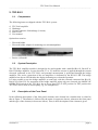
OPERATING INSTRUCTIONS AND SYSTEM DESCRIPTION FOR THE TEC-B-01 VOLTAGE CLAMP UNIT FOR BRIDGE AMPLIFIERS scaled for use in leech neuron experiments VERSION 1.0 npi 2011 npi electronic GmbH, Hauptstrasse 96, D-71732 Tamm, Germany Phone +49 (0)7141-9730230; Fax: +49 (0)7141-9730240 [email protected]; http://www.npielectronic.com TEC-B-01 User Manual ____________________________________________________________________________________________________________________________ Table of Contents 1. Safety Regulations...............................................................................................................3 2. TEC-B-01 ............................................................................................................................4 2.1. Components .................................................................................................................4 2.2. System Description ......................................................................................................4 2.3. Description of the Front Panel .....................................................................................4 Current Headstage Bias Current Adjustment for TEC-B-01 .......................................7 Tuning procedure: ........................................................................................................7 2.4. Description of the Rear Panel ......................................................................................9 3. Operation.............................................................................................................................9 3.1. Stand Alone Operation.................................................................................................9 3.2. Operation with Bridge Amplifier.................................................................................9 4. Simple cell model................................................................................................................10 4.1. Operation......................................................................................................................10 5. Technical Data.....................................................................................................................10 __________________________________________________________________________________ version 1.0 page 2 TEC-B-01 User Manual ____________________________________________________________________________________________________________________________ 1. Safety Regulations VERY IMPORTANT: Instruments and components supplied by npi electronic are NOT intended for clinical use or medical purposes (e.g. for diagnosis or treatment of humans), or for any other life-supporting system. npi electronic disclaims any warranties for such purpose. Equipment supplied by npi electronic must be operated only by selected, trained and adequately instructed personnel. For details please consult the GENERAL TERMS OF DELIVERY AND CONDITIONS OF BUSINESS of npi electronic, D-71732 Tamm, Germany. 1) GENERAL: This system is designed for use in scientific laboratories and must be operated only by trained staff. General safety regulations for operating electrical devices should be followed. 2) AC MAINS CONNECTION: While working with npi systems, always adhere to the appropriate safety measures for handling electronic devices. Before using any device please read manuals and instructions carefully. The device is to be operated only at 115/230 Volt 60/50 Hz AC. Please check for appropriate line voltage before connecting any system to mains. Always use a three-wire line cord and a mains power-plug with a protection contact connected to ground (protective earth). Before opening the cabinet, unplug the instrument. Unplug the instrument when replacing the fuse or changing line voltage. Replace fuse only with an appropriate specified type. 3) STATIC ELECTRICITY: Electronic equipment is sensitive to static discharges. Some devices such as sensor inputs are equipped with very sensitive FET amplifiers, which can be damaged by electrostatic charge and must therefore be handled with care. Electrostatic discharge can be avoided by touching a grounded metal surface when changing or adjusting sensors. Always turn power off when adding or removing modules, connecting or disconnecting sensors, headstages or other components from the instrument or 19” cabinet. 4) TEMPERATURE DRIFT / WARM-UP TIME: All analog electronic systems are sensitive to temperature changes. Therefore, all electronic instruments containing analog circuits should be used only in a warmed-up condition (i.e. after internal temperature has reached steady-state values). In most cases a warm-up period of 20-30 minutes is sufficient. 5) HANDLING: Please protect the device from moisture, heat, radiation and corrosive chemicals. __________________________________________________________________________________ version 1.0 page 3 TEC-B-01 User Manual ____________________________________________________________________________________________________________________________ 2. TEC-B-01 2.1. Components The following items are shipped with the TEC-B-01 system: TEC-B-01 amplifier Headstage Ground connector for headstage (2.6 mm) Power cord User manual Optional accessories: Electrode holder Electrode holder adapter for mounting to a micromanipulator Passive cell model 2.2. System Description The TEC-B-01 amplifier module is designed to be used together with a modified BA-1S, BA-01X or BA-03X bridge amplifier. In two-electrode CC or VC mode the current is applied through the current electrode connected to the TEC-B-01 and potential measurement is performed through the bridge amplifier. The active connection of the two amplifiers is indicated by the DUAL LED. The bridge amplifier has also an LED besides the display indicating two-electrode operation. It is also possible to use the bridge amplifier as usual only with the electrode connected the BA-1S, BA-01X or BA-03X. For operation of the bridge amplifier using only one electrode, the MODE OF OPERATION switch of the TEC-B-01 has to be set into EXT or OFF position. In EXT position the TEC-B-01 can be used as current pump, e.g. for iontophoresis. 2.3. Description of the Front Panel In the following description of the front panel elements each element has a number that is related to that in Figure 1. The number is followed by the name (in uppercase letters) written on the front panel and the type of the element (in lowercase letters). Then, a short description of the element is given. __________________________________________________________________________________ version 1.0 page 4 TEC-B-01 User Manual ____________________________________________________________________________________________________________________________ Figure 1: front panel view of the TEC-B-01 __________________________________________________________________________________ version 1.0 page 5 TEC-B-01 User Manual ____________________________________________________________________________________________________________________________ (1) MODE OF OPERATION switch Switch to select the MODE OF OPERATION: VC: OFF: CC: Voltage Clamp In this position the current injection of the amplifier is switched OFF, e.g. for operating the bridge amplifier as stand-alone device Current Clamp with current injection through the current headstage Note: In CC operation the current stimulus input of the bridge amplifier is used! EXT.: POWER OFF: EXTernal control. For operating the TEC-B-01 amplifier as a constant current source, e.g. for iontophoresis, or for operating the bridge amplifier as stand-alone device Power is turned OFF (2) GAIN VC potentiometer 10-turn potentiometer to set amplification factor (GAIN) of the VC error signal. To keep the VC error as small as possible it is necessary to use high GAIN settings, but the system becomes unstable and begins to oscillate if the GAIN is set too high. (3) Rs COMP. potentiometer 10-turn potentiometer to set the amount of series resistance compensation. Series resistance compensation improves the performance of the clamp system, especially if fast voltage-activated currents are recorded. Important: Series resistance compensation is done by positive feedback in the control circuit, which can lead very quickly to stability problems. Therefore, tuning of the series resistance compensation has to be carried out with great care! (4) CURRENT FILTER (Hz) switch 6-position switch to set the corner frequency of the CURRENT FILTER (100, 300, 500, 1k, 3k or 5k Hz) available at #17. (5) CUR. OUTP. SENS. (V/µA) switch Switch to set the amplification of the current signal at #17 (1 V / µA, 10 V / µA, 100 V / µA). (6) HOLDING POTENTIAL potentiometer 10-turn potentiometer for setting the HOLDING POTENTIAL in VC mode (7) + /0 /- switch Switch for setting the polarity of the HOLDING POTENTIAL in VC mode. In 0 position the HOLDING POTENTIAL is disabled, i.e. set to 0 mV. (8) DUAL LED LED indicating operation with the a bridge amplifier in CC or VC mode. __________________________________________________________________________________ version 1.0 page 6 TEC-B-01 User Manual ____________________________________________________________________________________________________________________________ (9) Display LED display for the CURRENT passed through the CURRENT electrode in µA (XX.XX µA, switch #10 in ICEL position) or the potential at the current electrode in mV (XXXX mV, switch #10 in VCEL position) or the resistance of the current electrode (XX.X M, switch #10 in RCEL position). (10) VCEL / ICEL / RCEL / switch 3-position switch for selection of the display mode: VCEL: potential of the current electrode is displayed ICEL: current value is displayed RCEL: resistance of the current electrode is displayed (11) OFFSET potentiometer 10-turn potentiometer to cancel potential OFFSETs at the current electrode. (12) BIAS CEL trim pot. Trim pot for adjusting the current headstage BIAS current. Current Headstage Bias Current Adjustment for TEC-B-01 Caution: It is important that this tuning procedure is performed ONLY after a warm-up period of at least 30 minutes! The tuning procedure should be performed regularly (at least once a month) with great care since the bias current changes over time and it determines the accuracy of the TEC-BA system. The TEC-B-01 is equipped with a current source that is connected to the current injecting electrode and performs the current injection. This current source has a high-impedance floating output. Therefore, the zero point (the zero of the BIAS current) of the current source must be defined, i.e. without an input signal there should not be an output current. The tuning procedure is done using the BIAS CEL trim pot and one resistance of a few k and one of a few M. It is based on Ohm's Law (U = R * I). If the headstage generates an output current, this current will cause a voltage deflection at a test resistor. If this test resistor has a low resistance of only a few k, this voltage deflection originates only from a possible offset of the electrode, that can be cancelled using the OFFSET CEL (#11, Figure 1) potentiometer. Replacing the low resistance resistor by one of a much higher resistance may lead to another voltage reading at the digital display. This voltage deflection then originates only from the BIAS output current and is proportional to this output current according to Ohm’s law. Using the BIAS CEL trim pot. the monitored voltage can be set to 0. This cancels the BIAS current. Tuning procedure: The tuning procedure is performed using high-value resistors. It cannot be performed with an electrode, since there are always unknown potentials involved (tip potential, junction potentials etc.). Warning: High voltage! Always turn power off when working directly on the current headstage output. __________________________________________________________________________________ version 1.0 page 7 TEC-B-01 User Manual ____________________________________________________________________________________________________________________________ Set the MODE OF OPERATION switch to OFF. Important: The tuning procedure must not be done in VC mode!! Connect the electrode connector of the TEC-B-01 headstage to ground. If parasitic oscillations occur use a 10 k resistor for grounding. Switch the digital display (#9) to VCEL (potential output of the current electrode) using switch #10. Set the reading of the display to 0 using the OFFSET potentiometer (#11). After tuning the current electrode potential OFFSET simulate an electrode by replacing the 10 k resistor with a much larger resistor (e.g. 1 M). The digital display (and the CURRENT ELECTRODE potential connector (CEL x10mV) (#18)) now shows a voltage deflection that is related to the BIAS current of the headstage according to Ohm's Law. Cancel this voltage by tuning the BIAS CEL trim pot (#12). The current is 0 if the voltage deflection is 0. Note: Due to the characteristics of the high voltage OPs the VCEL display may fluctuate around the baseline of 0 mV by some mV. With a 1 M resistor (as used in the cell model) 1 mV corresponds to 1 nA. Keeping in mind that the display accuracy of the current is 10 nA in the last digit this is insignificant. Important: The bridge amplifier it has a BIAS current as well and must be adjusted as described in the bridge amplifier user manual. (13) CAP.COMP. potentiometer Control for the capacity compensation of the CURRENT electrode or the signal connected to the EXT IN connector #16 (potentiometer with OFF position, clockwise). (14) Current HEADSTAGE connector Connector for the current headstage. (15) COMMAND IN ÷10 mV connector BNC connector for an external COMMAND voltage in VC mode (sensitivity: ÷10 mV). The signal form remains unchanged. (16) EXT IN 1 µA/V connector BNC connector for connecting an external voltage signal. This can be used to operate the TEC-B-01 module as a constant current source, e.g. for iontophoresis. Scaling is 1 µA / V, i.e. 100 mV connected at EXT IN leads to a current of 100 nA at the current electrode. (17) CURRENT OUT connector BNC connector providing the current signal. The scaling is set by switch #5. The filter is set by switch #4. (18) CEL x10 mV connector BNC connector providing the potential of the current electrode. __________________________________________________________________________________ version 1.0 page 8 TEC-B-01 User Manual ____________________________________________________________________________________________________________________________ (19) ms INTEGRATION potentiometer The integrator improves control performance for slower signals. Position OFF disables the integrator. Setting a time constant by turning the potentiometer clockwise converts the controller into a PI (proportional-integral) system. Time constant range is 10…0.1 ms. 2.4. Description of the Rear Panel A cable is firmly connected for linking the TEC-B-01 amplifier to the bridge amplifier connector TO TEC-B-01 at the rear panel of the bridge amplifier. CHASSIS This connector is linked to mains ground (green / yellow wire, protective earth). GROUND This connector is linked to the internal system ground which has no connection to the 19" cabinet (CHASSIS) and the mains ground to avoid ground loops. 3. Operation The TEC-B-01 can be operated as a stand-alone device or in conjunction with a modified bridge amplifier. 3.1. Stand Alone Operation The TEC-B-01 can be used as a current pump, e.g. for iontophoresis. The MODE OF OPERATION switch (#1, Figure 1). A voltage signal is connected to the EXT IN BNC connector (#16, Figure 1). This voltage signal is converted into a current signal with a scaling of 1 µA / V. The (mostly rectangular) shape of the input signal can be influenced by the capacity compensation. 3.2. Operation with Bridge Amplifier Together with a modified bridge amplifier the TEC-B-01 can be used for two electrode voltage clamp (TEVC) or two electrode current clamp (TECC) experiments. The scaling is adapted for current ranges normally used in experiments in leech neurons. For two electrode operation the TEC-B-01 and bridge amplifier are connected with a cable at the rear panel. The operation mode switch (#1, Figure 1) is set to CC (for current clamp) or VC (for voltage clamp). The current electrode is connected to the TEC-B-01 headstage and the potential electrode to the headstage of the bridge amplifier. Since in leech neurons usually the x10 voltage range the bridge amplifier is automatically set into the x10 mode if functionally connected to the TEC-B-01. In two electrode operation current injection is done with the current electrode (connected to the TECB-01) and potential measurement with the potential electrode. This applies to both, CC and VC modes. Two electrode operation is indicated by the DUAL LED at the TEC-01-B as well as by the DUAL LED at the bridge amplifier. __________________________________________________________________________________ version 1.0 page 9 TEC-B-01 User Manual ____________________________________________________________________________________________________________________________ 4. Simple cell model A very simple cell model is also provided. It consists of passive elements which simulate electrode resistances, series resistance and capacity and resistance of the cell membrane. Figure 2: simple cell model of the TEC-B-01-BA system Electrode resistances: 15 M for each electrode RS switch: ON / OFF switch for setting a series resistance of 20 k C: cell either with 100 k or 1 M membrane resistance, membrane capacity is always 3.9 nF 4.1. Operation Connect the white cable to the core of the BNC connector of the TEC-B-01 amplifier Connect the grey cable to the core of the BNC connector of the BA amplifier Connect the black ground cable to GND of one of the headstages Select the desired membrane resistance Select whether to mimic a series resistance or not. 5. Technical Data Modes of Operation CC: VC: OFF: EXT: MODE selection: Current Clamp mode Voltage Clamp mode Current- and Voltage Clamp disabled, BA amplifier operational External mode by rotary switch __________________________________________________________________________________ version 1.0 page 10 TEC-B-01 User Manual ____________________________________________________________________________________________________________________________ Headstages Potential headstage Bridge amplifier headstage is used for potential measurement Current headstage Operating voltage: Input resistance: Electrode connector: Ground: Size: Holding bar: ±45 V >1012 BNC, shield is grounded 2.4 mm connector or headstage enclosure 23 x 70 x 26 mm, enclosure grounded diameter 8 mm, length 10 cm Current range: 450 nA / 100 M or 4.5 µA / 10 M Current electrode parameter controls: Offset compensation: ten-turn control, ±1200 mV Electrode Resistance Test: obtained by application of square current pulses ±10 nA, display XX.X M, selected by switch Current Outputs: Filtered output: sensitivity: set by current range switch, with low-pass Bessel filter, output impedance 50 Current range switch: 1 µA / V, 10 µA / V or 100 µA / V DISPLAY: XX.XX µA Current Output Filters: One-pole low-pass Bessel filter 6 corner frequencies: 100, 300, 500, 1k, 3k or 5k Hz. Current Clamp (current stimulus input from bridge amplifier): Inputs: Input impedance: HOLD: 100 nA / V >100 k X.XX µA, ten-turn digital control with -/0/+ switch, maximum 1000 nA. Voltage Clamp: Input sensitivity: Input impedance HOLD: 10 mV >100 k XXX mV, ten-turn digital control with +/0/- switch, maximum 1000 mV __________________________________________________________________________________ version 1.0 page 11