1
EPD®.Connect
User Guide
Optegra® Release 7
DOC40159-013
Parametric Technology Corporation
Copyright © 2002 Parametric Technology Corporation. All Rights Reserved.
User and training documentation from Parametric Technology Corporation (PTC) is subject to the copyright laws
of the United States and other countries and is provided under a license agreement that restricts copying,
disclosure, and use of such documentation. PTC hereby grants to the licensed user the right to make copies in
printed form of this documentation if provided on software media, but only for internal/personal use and in
accordance with the license agreement under which the applicable software is licensed. Any copy made shall
include the PTC copyright notice and any other proprietary notice provided by PTC. This documentation may not
be disclosed, transferred, modified, or reduced to any form, including electronic media, or transmitted or made
publicly available by any means without the prior written consent of PTC and no authorization is granted to make
copies for such purposes.
Information described herein is furnished for general information only, is subject to change without notice, and
should not be construed as a warranty or commitment by PTC. PTC assumes no responsibility or liability for any
errors or inaccuracies that may appear in this document.
The software described in this document is provided under written license agreement, contains valuable trade
secrets and proprietary information, and is protected by the copyright laws of the United States and other
countries. It may not be copied or distributed in any form or medium, disclosed to third parties, or used in any
manner not provided for in the software licenses agreement except with written prior approval from PTC.
UNAUTHORIZED USE OF SOFTWARE OR ITS DOCUMENTATION CAN RESULT IN CIVIL DAMAGES AND
CRIMINAL PROSECUTION.
Registered Trademarks of Parametric Technology Corporation or a Subsidiary
Advanced Surface Design, CADDS, Computervision, Computervision Services, Electronic Product Definition,
EPD, EPD.Connect, Expert Machinist, Flexible Engineering, HARNESSDESIGN, Info*Engine, InPart, Optegra,
Parametric Technology, Parametric Technology Corporation, PHOTORENDER, Pro/DESKTOP, Pro/E,
Pro/ENGINEER, Pro/HELP, Pro/INTRALINK, Pro/MECHANICA, Pro/TOOLKIT, PTC, PT/Products,
Shaping Innovation, and Windchill.
Trademarks of Parametric Technology Corporation or a Subsidiary
3DPAINT, Associative Topology Bus, Behavioral Modeling, CDRS, CounterPart, Create Collaborate Control, CV,
CVact, CVaec, CVdesign, CV-DORS, CVMAC, CVNC, CVToolmaker, DataDoctor, DesignSuite, DIMENSION III,
DIVISION, DVS, DVSAFEWORK, EDE, e/ENGINEER, Electrical Design Entry, EMX, eNC Explorer,
Expert MoldBase, Expert Toolmaker, GRANITE, ISSM, KDiP, Knowledge Discipline in Practice,
Knowledge System Driver, ModelCHECK, MoldShop, NC Builder, PartSpeak, Pro/ANIMATE, Pro/ASSEMBLY,
Pro/CABLING, Pro/CASTING, Pro/CDT, Pro/CMM, Pro/COLLABORATE, Pro/COMPOSITE, Pro/CONCEPT,
Pro/CONVERT, Pro/DATA for PDGS, Pro/DESIGNER, Pro/DETAIL, Pro/DIAGRAM, Pro/DIEFACE, Pro/DRAW,
Pro/ECAD, Pro/ENGINE, Pro/FEATURE, Pro/FEM-POST, Pro/FICIENCY, Pro/FLY-THROUGH, Pro/HARNESS,
Pro/INTERFACE, Pro/LANGUAGE, Pro/LEGACY, Pro/LIBRARYACCESS, Pro/MESH, Pro/Model.View,
Pro/MOLDESIGN, Pro/NC-ADVANCED, Pro/NC-CHECK, Pro/NC-MILL, Pro/NCPOST, Pro/NC-SHEETMETAL,
Pro/NC-TURN, Pro/NC-WEDM, Pro/NC-Wire EDM, Pro/NETWORK ANIMATOR, Pro/NOTEBOOK, Pro/PDM,
Pro/PHOTORENDER, Pro/PIPING, Pro/PLASTIC ADVISOR, Pro/PLOT, Pro/POWER DESIGN, Pro/PROCESS,
Pro/REPORT, Pro/REVIEW, Pro/SCAN-TOOLS, Pro/SHEETMETAL, Pro/SURFACE, Pro/VERIFY, Pro/Web.Link,
Pro/Web.Publish, Pro/WELDING, Product Development Means Business, Product First, Products First,
ProductView, PTC Precision, Shrinkwrap, The Product Development Company, The Way to Product First,
Wildfire, Windchill DynamicDesignLink, Windchill PartsLink, Windchill PDMLink, Windchill ProjectLink, and
Windchill SupplyLink.
Third-Party Trademarks
Adobe is a registered trademark of Adobe Systems. Advanced ClusterProven, ClusterProven, and the
ClusterProven design are trademarks or registered trademarks of International Business Machines Corporation in
the United States and other countries and are used under license. IBM Corporation does not warrant and is not
responsible for the operation of this software product. AIX is a registered trademark of IBM Corporation. Allegro,
Cadence, and Concept are registered trademarks of Cadence Design Systems, Inc. AutoCAD is a registered
trademark of Autodesk, Inc. Baan is a registered trademark of Baan Company. CADAM and CATIA are registered
trademarks of Dassault Systemes. COACH is a trademark of CADTRAIN, Inc. DOORS is a registered trademark
of Telelogic AB. FLEXlm is a registered trademark of GLOBEtrotter Software, Inc. Geomagic is a registered
trademark of Raindrop Geomagic, Inc. EVERSYNC, GROOVE, GROOVEFEST, GROOVE.NET,
GROOVE NETWORKS, iGROOVE, PEERWARE, and the interlocking circles logo are trademarks of Groove
Networks, Inc. Helix is a trademark of Microcadam, Inc. HOOPS is a trademark of Tech Soft America, Inc. HP-UX
is a registered trademark and Tru64 is a trademark of the Hewlett-Packard Company. I-DEAS, Metaphase,
Parasolid, SHERPA, Solid Edge, and Unigraphics are trademarks or registered trademarks of Electronic Data
Systems Corporation (EDS). InstallShield is a registered trademark and service mark of InstallShield Software
Corporation in the United States and/or other countries. Intel is a registered trademark of Intel Corporation. IRIX is
a registered trademark of Silicon Graphics, Inc. MatrixOne is a trademark of MatrixOne, Inc. Mentor Graphics and
Board Station are registered trademarks and 3D Design, AMPLE, and Design Manager are trademarks of
Mentor Graphics Corporation. Netscape and the Netscape N and Ship’s Wheel logos are registered trademarks of
Netscape Communications Corporation in the U.S. and other countries. Oracle is a registered trademark of
Oracle Corporation. OrbixWeb is a registered trademark of IONA Technologies PLC. PDGS is a registered
trademark of Ford Motor Company. RAND is a trademark of RAND Worldwide. Rational Rose is a registered
trademark of Rational Software Corporation. RetrievalWare is a registered trademark of Convera Corporation.
RosettaNet is a trademark and Partner Interface Process and PIP are registered trademarks of "RosettaNet," a
non-profit organization. SAP and R/3 are registered trademarks of SAP AG Germany. SolidWorks is a registered
trademark of SolidWorks Corporation. All SPARC trademarks are used under license and are trademarks or
registered trademarks of SPARC International, Inc. in the United States and in other countries. Products bearing
SPARC trademarks are based upon an architecture developed by Sun Microsystems, Inc. STHENO is a
trademark of CAD Schroer GmbH. Sun, Sun Microsystems, the Sun logo, Solaris, UltraSPARC, Java and all Java
based marks, and "The Network is the Computer" are trademarks or registered trademarks of Sun Microsystems,
Inc. in the United States and in other countries. VisTools is a trademark of Visual Kinematics, Inc. (VKI).
VisualCafé is a trademark of WebGain, Inc. WebEx is a trademark of WebEx Communications, Inc. Microsoft,
Windows, Windows NT, Visual Basic, and the Visual Basic logo are registered trademarks of Microsoft
Corporation in the United States and/or other countries.
Licensed Third-Party Technology Information
Certain PTC software products contain licensed third-party technology: Rational Rose 2000E is copyrighted
software of Rational Software Corporation. RetrievalWare is copyrighted software of Convera Corporation.
VisualCafé is copyrighted software of WebGain, Inc. VisTools library is copyrighted software of
Visual Kinematics, Inc. (VKI) containing confidential trade secret information belonging to VKI. HOOPS graphics
system is a proprietary software product of, and is copyrighted by, Tech Soft America, Inc. G-POST is copyrighted
software and a registered trademark of Intercim. VERICUT is copyrighted software and a registered trademark of
CGTech. Pro/PLASTIC ADVISOR is powered by Moldflow technology. Moldflow is a registered trademark of
Moldflow Corporation. The JPEG image output in the Pro/Web.Publish module is based in part on the work of the
independent JPEG Group. DFORMD.DLL is copyrighted software from Compaq Computer Corporation and may
not be distributed. METIS, developed by George Karypis and Vipin Kumar at the University of Minnesota, can be
researched at http://www.cs.umn.edu/~karypis/metis. METIS is © 1997 Regents of the University of Minnesota.
LightWork Libraries are copyrighted by LightWork Design 1990-2001. Visual Basic for Applications and
Internet Explorer is copyrighted software of Microsoft Corporation. Adobe Acrobat Reader is copyrighted software
of Adobe Systems. Parasolid © Electronic Data Systems (EDS). Windchill Info*Engine Server contains IBM XML
Parser for Java Edition and the IBM Lotus XSL Edition. Pop-up calendar components Copyright © 1998 Netscape
Communications Corporation. All Rights Reserved. TECHNOMATIX is copyrighted software and contains
proprietary information of Technomatix Technologies Ltd. Apache Server, Tomcat, Xalan, and Xerces are
technologies developed by, and are copyrighted software of, the Apache Software Foundation
(http://www.apache.org/) – their use is subject to the terms and limitations at: http://www.apache.org/LICENSE.txt.
UnZip (© 1990-2001 Info-ZIP, All Rights Reserved) is provided "AS IS" and WITHOUT WARRANTY OF ANY
KIND. For the complete Info-ZIP license see ftp://ftp.info-zip.org/pub/infozip/license.html. Gecko and Mozilla
components are subject to the Mozilla Public License Version 1.1 at http://www.mozilla.org/MPL/. Software
distributed under the MPL is distributed on an "AS IS" basis, WITHOUT WARRANTY OF ANY KIND, either
express or implied. See the MPL for the specific language governing rights and limitations.
Technology "Powered by Groove" is provided by Groove Networks, Inc. Technology "Powered by WebEx" is
provided by WebEx Communications, Inc. Acrobat Reader is Copyright © 1998 Adobe Systems Inc.
Oracle 8i run-time, Copyright © 2000 Oracle Corporation. The JavaTM Telnet Applet (StatusPeer.java,
TelnetIO.java, TelnetWrapper.java, TimedOutException.java), Copyright © 1996, 97 Mattias L. Jugel,
Marcus Meißner, is redistributed under the GNU General Public License. This license is from the original copyright
holder and the Applet is provided WITHOUT WARRANTY OF ANY KIND. You may obtain a copy of the source
code for the Applet at http://www.mud.de/se/jta (for a charge of no more than the cost of physically performing the
source distribution), by sending an e-mail to [email protected] or [email protected]—you are allowed to choose either
distribution method. The source code is likewise provided under the GNU General Public License.
GTK+The GIMP Toolkit are licensed under the GNU LPGL. You may obtain a copy of the source code at
http://www.gtk.org/, which is likewise provided under the GNU LPGL.
UNITED STATES GOVERNMENT RESTRICTED RIGHTS LEGEND
This document and the software described herein are Commercial Computer Documentation and Software,
pursuant to FAR 12.212(a)-(b) (OCT’95) or DFARS 227.7202-1(a) and 227.7202-3(a) (JUN’95), is provided to the
US Government under a limited commercial license only. For procurements predating the above clauses, use,
duplication, or disclosure by the Government is subject to the restrictions set forth in subparagraph (c)(1)(ii) of the
Rights in Technical Data and Computer Software Clause at DFARS 252.227-7013 (OCT’88) or Commercial
Computer Software-Restricted Rights at FAR 52.227-19(c)(1)-(2) (JUN’87), as applicable.
110102
Parametric Technology Corporation, 140 Kendrick Street, Needham, MA 02494 USA
Table of Contents
Preface
Related Documents ________________________________________ xxi
Book Conventions __________________________________________ xxii
Online User Documentation ________________________________ xxiii
Printing Documentation ___________________________________ xxiii
Resources and Services ____________________________________ xxiv
Documentation Comments ________________________________ xxiv
EPD.Connect Overview
About EPD.Connect _____________________________________________ 1-2
An EPD.Connect Scenario _______________________________________ 1-3
Advantages of EPD.Connect__________________________________ 1-7
EPD.Connect Components ______________________________________ 1-8
Basic Components ___________________________________________ 1-8
Information Browser________________________________________ 1-8
Product Structure Window ________________________________ 1-10
Data Browser _____________________________________________ 1-12
3-Dimensional Viewer _____________________________________ 1-12
Optional Components _______________________________________
Database ________________________________________________
Dynamic Application Interfaces ___________________________
EPD.Visualizer ____________________________________________
MockUp _________________________________________________
Web Browser _____________________________________________
EPD.Connect User Guide
1-13
1-14
1-14
1-15
1-15
1-16
Contents-v
EPD.Connect Support for Topology Bus __________________________ 1-17
Limitations and Restrictions __________________________________ 1-18
Accessing and Exiting EPD.Connect _____________________________ 1-19
Exiting EPD.Connect _________________________________________ 1-19
Displaying EPD.Connect on Sun Solaris from HP-UX _______________ 1-20
Customizing EPD.Connect ______________________________________ 1-21
Customizing with Perl _____________________________________ 1-21
Symmetry in EPD.Connect ______________________________________ 1-22
Symmetry ________________________________________________ 1-22
Mirroring _________________________________________________ 1-22
Components Modified During Mirroring _______________________ 1-23
Features ____________________________________________________ 1-24
Limitations and Restrictions __________________________________ 1-25
SYMMETRY-FLAG Attribute ___________________________________ 1-25
Navigator License Considerations in EPD.Connect _______________ 1-27
Restrictions__________________________________________________ 1-27
Where to Look for Information __________________________________ 1-28
Using the Product Structure Window
Product Structure Window ________________________________________ 2-2
Using the Product Structure Window_______________________________ 2-3
Product Structure Window Toolbar _____________________________ 2-4
EPD.Connect Toolbar for the Product Structure Window _________ 2-5
Mouse Behavior _______________________________________________ 2-6
Creating a New Product Structure Tree ____________________________ 2-8
Opening a Product Structure Tree _________________________________ 2-9
Opening a Product Structure Tree from a Local Disk ____________ 2-9
Displaying Subtree Components _____________________________ 2-10
Retrieving Associated Attributes ______________________________ 2-10
Opening a Product Structure with TIM Components ___________ 2-11
Working with Four Product Structure Windows ____________________ 2-12
Contents-vi
EPD.Connect User Guide
Displaying Multiple Product Structure Configurations
in EPD.Visualizer or 3D Viewer ________________________________ 2-12
Identifying the Product Structure Window from Which a
Component is Loaded _______________________________________ 2-13
Comparing Tree Components Across Product Structure
Windows ____________________________________________________ 2-13
Highlighting Components by Zone Across Product Structure
Windows ____________________________________________________ 2-14
Performing Clash Detection Across Product Structure
Windows ____________________________________________________ 2-14
Identifying a Product Structure Window by the Name _________ 2-15
Closing and Expanding Reference Components ________________ 2-16
Expanding One or More Reference Components _____________ 2-16
Refreshing Expanded Reference Components ________________ 2-16
Closing One or More Reference Components _________________ 2-17
Expanding and Closing Hidden Reference Components_______ 2-17
Hiding Selected or Highlighted Components _____________________ 2-18
Example _________________________________________________ 2-18
Editing Component Attributes ___________________________________ 2-19
Defining Assembly Attributes and Values Externally ____________ 2-21
Using Local Memory for Tree Manipulation _______________________ 2-23
Compress Mode__________________________________________ 2-24
Comparing Two Trees___________________________________________ 2-25
Obtaining a Comparison Report __________________________ 2-28
Saving a Report __________________________________________ 2-29
Printing a Report__________________________________________ 2-29
Comparing TIM Components_________________________________ 2-29
Saving and Closing a Product Structure Tree _____________________ 2-30
Saving a Product Structure Tree Locally ______________________ 2-30
Saving a Product Structure Tree as a New Tree ________________ 2-30
Saving a Subset of the Tree __________________________________ 2-31
Saving the TIM Components of a Product Structure Tree _______ 2-31
Closing a Product Structure Tree _____________________________ 2-32
Status and Report Windows ____________________________________ 2-33
EPD.Connect User Guide
Contents-vii
Session Summary ____________________________________________ 2-33
General Tab _____________________________________________ 2-34
Structure Tab _____________________________________________ 2-34
Component Status __________________________________________ 2-35
Component Comparison Status _____________________________ 2-36
ADRAW Items _______________________________________________ 2-37
Indicator Key _______________________________________________ 2-37
Clip Board __________________________________________________ 2-38
Audit Log ___________________________________________________ 2-38
Working with Multiple CVPATHS _________________________________ 2-39
Setting the CVPATH Variable _________________________________ 2-40
Selecting a CVPATH _________________________________________ 2-41
Editing a CVPATH ___________________________________________ 2-42
Printing and Displaying Reports _________________________________ 2-44
Printing Product Structures ______________________________________ 2-47
Plotting a Tree Structure ________________________________________ 2-49
Creating a Binary CGM File __________________________________ 2-49
Plotting a Tree_______________________________________________ 2-50
Plotting from the File ______________________________________ 2-51
Plotting from the Product Structure Tree ___________________ 2-52
Setting Variables for Plotting _________________________________ 2-53
Launching Applications from Product Structure Components _____ 2-55
Launching Applications______________________________________ 2-55
Defining Component/Application Associations _______________
Defining an Application Environment ______________________
Associating Components with Applications ________________
Editing the launch.ini file __________________________________
Editing the cvepd.ini File _________________________________
2-55
2-56
2-57
2-57
2-58
Creating and Editing a Product Structure Tree
The Edit Menu____________________________________________________ 3-2
Options for Editing Components _______________________________ 3-2
Editing the Properties of a TIM Component _____________________ 3-3
Contents-viii
EPD.Connect User Guide
Limitations and Restrictions _________________________________ 3-3
Adding Components ___________________________________________ 3-4
Creating New Components ___________________________________ 3-4
Adding a Component with Mirror Flag ______________________ 3-7
Example __________________________________________________ 3-7
Adding a Component on a Compressed Node ________________ 3-7
Adding TIM Components _____________________________________ 3-8
Editing the Tree Structure ________________________________________ 3-9
Cutting and Pasting the Components _________________________ 3-9
Copying Components _______________________________________ 3-10
Copying and Pasting from the Data Browser __________________ 3-11
Undoing and Restoring Previous Editing _______________________ 3-12
Swapping Component Positions _____________________________ 3-12
Reordering Components_____________________________________ 3-13
Positioning Components __________________________________ 3-13
Sorting Components ______________________________________ 3-14
Setting Global Attributes ________________________________________ 3-16
Copying Instance Attributes _________________________________ 3-17
Setting Revision Levels __________________________________________ 3-18
Setting Revision Levels of a Component ___________________ 3-18
Changing the Revision Levels of a Component_____________ 3-18
Customizing the Product Structure Tree Window
Selecting and Displaying Components ___________________________ 4-2
Setting the Component Selection __________________________ 4-2
Setting Component Text Display ____________________________ 4-3
Setting the Component Text Font ___________________________ 4-5
Setting the Component Display Rules_____________________________ 4-6
Creating Access Indicator Rules ______________________________
Changing a Rule __________________________________________
Deleting a Rule ____________________________________________
Selecting Components by the Access Indicator _____________
4-6
4-9
4-9
4-9
Creating Highlighting Rules _________________________________ 4-10
Highlighting by Value _____________________________________ 4-11
EPD.Connect User Guide
Contents-ix
Highlighting by Attribute __________________________________ 4-12
Creating Display Rules _______________________________________ 4-14
Example _________________________________________________ 4-16
Creating a Display Rules Template ___________________________ 4-16
Retrieving a Template _______________________________________ 4-18
Defining the Display State for TIM Components __________________ 4-19
Saving Display States ___________________________________________ 4-20
Restoring Display States_________________________________________ 4-21
Compressing a Display Structure ________________________________ 4-22
Uncompressed Node ________________________________________ 4-22
Compressed Node __________________________________________ 4-23
Example: Screws in an Assembly __________________________ 4-24
Advantages ________________________________________________ 4-24
Limitations __________________________________________________ 4-24
Global Renumbering of Nodes __________________________________ 4-25
Renumbering Nodes of All Classes____________________________ 4-25
Renumbering Nodes of a Specific Class ______________________ 4-25
Browsing for Components ______________________________________ 4-26
Creating and Clearing Display Conditions _______________________ 4-29
View Menu _________________________________________________ 4-29
Clear Menu ________________________________________________ 4-31
Using the 3D Viewer
About 3D Viewer _________________________________________________ 5-2
Mouse Behavior _______________________________________________ 5-2
3D Viewer Operations _________________________________________ 5-2
Setting the Viewer Session ________________________________________ 5-4
Creating a New Session________________________________________ 5-4
Opening a Graphics File from the 3D Viewer ____________________ 5-4
Opening a Graphics File from the Product Structure Window ____ 5-5
Setting the View _________________________________________________ 5-6
Contents-x
EPD.Connect User Guide
Resetting the Primary View ____________________________________ 5-6
Setting a New Primary View ___________________________________ 5-6
Viewing All Components ______________________________________ 5-6
Zooming _____________________________________________________ 5-6
Setting the Camera _____________________________________________ 5-7
Setting the Camera Position___________________________________ 5-7
Setting the Camera Target ____________________________________ 5-7
Setting the Camera Position and Target _______________________ 5-7
Measuring Distance _____________________________________________ 5-8
Measuring Distance from Camera to Point _____________________ 5-8
Measuring Distance Between Two Points _______________________ 5-8
Rendering _____________________________________________________ 5-10
Rendering Methods _________________________________________ 5-10
Back Facing Polygons _______________________________________ 5-11
Display Buffering ____________________________________________ 5-11
Moving the Camera ____________________________________________ 5-12
Moving the Camera in an Angular Direction __________________ 5-12
Moving the Camera in a Linear Direction _____________________ 5-13
Setting the Working Units________________________________________ 5-15
Selecting and Scrolling _________________________________________ 5-17
Running Custom Reports _____________________________________ 5-17
Selecting Application Objects __________________________________ 5-18
Display Menu __________________________________________________ 5-19
Loading Tree Components into the 3D Viewer (Load) _________ 5-20
Deleting Components from the 3D Viewer (Delete)____________ 5-20
Converting CADDS Parts to Graphic Files (Convert) ___________ 5-20
Showing Components (Show) ________________________________ 5-21
Hiding Components (Hide) ___________________________________ 5-21
Selecting Components (Select) ______________________________ 5-21
Incrementally Selecting Components in the 3D Viewer _____ 5-22
Selecting Components in the 3D Viewer ___________________ 5-22
Deselecting Components (Deselect) _________________________ 5-23
EPD.Connect User Guide
Contents-xi
Incrementally Deselecting Components in the 3D Viewer ___ 5-23
Highlighting Components (Highlight) _________________________
Highlighting the Selected Components ____________________
Highlighting the Components Incrementally _______________
Highlighting Only Selected Components ___________________
Highlighting Only Highlighted Components ________________
5-24
5-24
5-24
5-24
5-25
Applying Transparency (Transparency) _______________________ 5-25
Resetting Colors (Color) _____________________________________ 5-25
Displaying Polygons (Options) ________________________________ 5-26
Using the Display Options — Examples ________________________
Displaying Selected Components _________________________
Displaying Highlighted Components _______________________
Hiding Only Selected Components ________________________
5-26
5-26
5-27
5-27
Exiting the 3D Viewer ___________________________________________ 5-28
Clash Detection and Zoning
Detecting Clashes _______________________________________________ 6-2
Clash Detection in the Foreground Mode _______________________ 6-3
Clash Detection in Background Mode __________________________ 6-5
Viewing Clash Detection Results _______________________________ 6-5
Hard Clash Detection_______________________________________ 6-6
Soft Clash Detection________________________________________ 6-6
Reporting Clash Detection Results ______________________________ 6-6
Zoning ___________________________________________________________ 6-7
Activating Zones ______________________________________________ 6-7
Zoning in Background Mode ___________________________________ 6-9
Working with Vault Data
The Data Browser Window ________________________________________ 7-2
Accessing the Vault ___________________________________________ 7-3
Using the Database Menu Options ________________________________ 7-4
Vault Signon and Signoff Procedures ___________________________ 7-5
Viewing Application Directories _______________________________ 7-6
Contents-xii
EPD.Connect User Guide
Setting Vault Access Defaults _________________________________ 7-7
Invoking Database Transfer Actions ___________________________ 7-8
Transferring Data and Starting Applications _________________ 7-8
Deferred Vault Transactions ________________________________ 7-9
Searching for a Component _________________________________ 7-10
Sending and Responding to Messages________________________ 7-11
Sending Messages to Other Users _________________________ 7-12
Reading Messages _______________________________________ 7-13
Changing the Vault User Password ___________________________ 7-14
Refreshing the DOD _________________________________________ 7-14
Refreshing the DOD Manually _____________________________ 7-14
Refreshing the DOD Automatically ________________________ 7-15
Using the Vault Menu Options ___________________________________ 7-16
Signing Out Vault Items ______________________________________ 7-17
Copying Vault Items to the Local Directory ___________________ 7-17
Updating Vault Items ________________________________________ 7-17
Replacing Vault Items _______________________________________ 7-17
Unlocking Vault Items ________________________________________ 7-18
Storing Items in Vault ________________________________________ 7-18
Storing a Single Item ______________________________________ 7-18
Storing Multiple Items _____________________________________ 7-19
Copying Vault Items _________________________________________ 7-21
Changing the Attributes of a Vault Item ______________________ 7-23
Editing Vault Attributes_______________________________________ 7-24
Changing the Status or Revision of a Vault Item _______________ 7-25
Reviewing Vault Items _______________________________________
Requesting Reviews ______________________________________
Requesting a Review of a Single Vault Item ________________
Requesting a Review of Multiple Vault Items _______________
7-26
7-26
7-27
7-28
Responding to Reviews ______________________________________ 7-30
Responding to a Review of a Single Vault Item _____________ 7-30
Responding to a Review of Multiple Vault Items ____________ 7-32
Working with Distributed Vaults _______________________________ 7-34
Registering Objects _______________________________________ 7-34
Unregistering Objects _____________________________________ 7-35
EPD.Connect User Guide
Contents-xiii
Registering And Unregistering ADRAWs Associated with
CAMU Files __________________________________________________ 7-36
Subscribing Objects _________________________________________ 7-37
Unsubscribing Objects ____________________________________ 7-40
Distributing Objects _______________________________________ 7-40
Listing Information about a Vault Item ________________________ 7-41
Obtaining Information from the Vault ___________________________ 7-43
Querying Vault Data _____________________________________
Customizing Query Results ________________________________
Saving the Query Results __________________________________
Opening a Tree Structure from the Vault __________________
7-43
7-46
7-48
7-48
Working with Vault Data Using the Information Browser ___________ 7-50
Using CAMU in EPD.Connect
Overview ________________________________________________________ 8-2
CADDS 5i and Optegra Interoperabilty in Non-English Locales ______ 8-3
EPD.Connect Interface for CADDS ________________________________ 8-4
epdconn.ini ___________________________________________________ 8-4
caddsrb.ini____________________________________________________ 8-8
EPD Interface for CADDS Support _______________________________ 8-10
General Process Flow ________________________________________ 8-12
Tree Structure and CAMU _________________________________ 8-12
Tree Structure Only _______________________________________ 8-12
Opening an Existing Assembly __________________________________ 8-15
Opening an Assembly Using the Data Browser Menu _______ 8-16
Opening an Assembly Using the Information Browser _______ 8-17
Opening a TIM Assembly_____________________________________ 8-17
Opening a New Assembly ______________________________________ 8-18
Opening Another Assembly from CAMU ______________________ 8-18
Opening an Assembly Using the Product Structure Menu ___ 8-19
Activating an Assembly From the CADDS LDM _____________ 8-19
Working on an Assembly________________________________________ 8-20
Using Attributes _____________________________________________ 8-20
Contents-xiv
EPD.Connect User Guide
Symmetry ___________________________________________________ 8-20
Using the Associative Topology Bus ______________________________ 8-22
Importing Pro/ENGINEER Parts and Assemblies ________________ 8-22
Exporting CADDS 5 Parts and Assemblies______________________ 8-22
Verifying TIM Parts and Assemblies____________________________ 8-23
Updating TIM Parts and Assemblies ___________________________ 8-23
Setting Variables for TIM Parts and Assemblies _________________ 8-24
Exiting CAMU and EPD.Connect_________________________________ 8-25
Using the Information Browser Assembly Tab _____________________ 8-26
Information Browser Options _________________________________ 8-26
Query Fields ______________________________________________ 8-26
File Menu ___________________________________________________
Filing an Assembly ________________________________________
Filing an Assembly with Options ___________________________
Quitting Suspended Parts _________________________________
Quitting and Exiting the Active Assembly___________________
Entering the CADDS Local Data Manager__________________
Closing the Current EPD.Connect Session __________________
8-27
8-28
8-28
8-28
8-28
8-28
8-28
Edit Menu ___________________________________________________ 8-29
CAMU Application Toolbar___________________________________ 8-30
Copying and Pasting from the Data Browser __________________ 8-33
Limitations _______________________________________________ 8-34
Performing Vault Operations on CADDS _________________________ 8-35
Overview ________________________________________________ 8-35
Features _________________________________________________ 8-35
EPD Interface to CADDS ________________________________________ 8-37
Store, Update, and Replace Commands __________________
GET Command ___________________________________________
READ Command _________________________________________
GET and READ Dependent Objects ________________________
8-37
8-38
8-38
8-39
Working with EPD.Connect______________________________________ 8-41
Working with the Product Structure Window___________________ 8-41
Working with the Data Browser _______________________________ 8-41
Creating Preprocessing and Postprocessing Routines __________ 8-42
EPD.Connect User Guide
Contents-xv
Vault Operations on CAMU Objects __________________________ 8-43
Migrating PS Files from EPD.Connect and CADDS 5 Revision 8.x
or Earlier _______________________________________________________ 8-44
Working with Dual Display
About Dual Display _______________________________________________ 9-2
Using Dual Display ________________________________________________ 9-3
Viewing EPD.Connect On One Display and EPD.Visualizer
On the Other_______________________________________________ 9-3
Viewing CADDS 5i On One Display and EPD.Connect
On the Other_______________________________________________ 9-3
Using the EPD.Connect Interface for DIVISION MockUp
Overview ______________________________________________________ 10-2
Features ____________________________________________________ 10-2
Setting the User Environment ____________________________________ 10-4
Identifying the Load Method ______________________________
Editing the GO Script _____________________________________
Setting the DIVISIONPATH Environment Variable ____________
Editing the dvise_epd_rc Script ____________________________
Customizing the EPD.Connect Tools Menu _________________
Other Integration Files ____________________________________
10-4
10-4
10-5
10-6
10-7
10-7
Environment Variables __________________________________________ 10-9
EPD.Connect Files _____________________________________________ 10-11
DIVISION MockUp Triggers _____________________________________ 10-12
System Requirements __________________________________________ 10-13
Communication between EPD.Connect and DIVISION
MockUp ______________________________________________________ 10-14
DIVISION MockUp/EPD.Connect Integration Files ________________ 10-17
Contents-xvi
EPD.Connect User Guide
Using the EPD Interface for MEDUSA
Overview ______________________________________________________ 11-2
File-Naming Conventions ____________________________________ 11-2
Features ____________________________________________________ 11-3
Limitations __________________________________________________ 11-3
Setting up MEDUSA Support on the Vault ________________________ 11-4
Creating Preprocessing and Postprocessing Routines _____________ 11-5
Sequence of Actions for MEDUSA Objects _______________________ 11-6
Working in EPD.Connect ________________________________________ 11-8
Using the EPD Interface for Pro/ENGINEER
Overview ______________________________________________________ 12-2
Features_______________________________________________________ 12-3
Limitations _____________________________________________________ 12-4
EPD Interface for Pro/ENGINEER Support _________________________ 12-5
Understanding the EPD Interface for
Pro/ENGINEER __________________________________________________ 12-6
Supported Objects and Optegra Commands _________________ 12-6
The store, update, and replace Commands __________________ 12-7
The get and read Commands________________________________ 12-7
Preprocessing and Postprocessing ______________________________ 12-8
Working in EPD.Connect ________________________________________ 12-9
Working with the Information Browser _________________________ 12-9
Working with the Data Browser _______________________________ 12-9
Using the EPD Interface for CATIA
Overview ______________________________________________________ 13-2
Features _______________________________________________________ 13-3
Limitations _____________________________________________________ 13-4
EPD.Connect User Guide
Contents-xvii
Working with CATIA Data in the Vault ___________________________ 13-5
Setting Up CATIA Support on Vault ________________________ 13-5
Querying Vault for CATIA Data ____________________________ 13-6
Working in EPD.Connect ________________________________________ 13-7
Working with the Information Browser _________________________ 13-7
Working with the Data Browser _______________________________ 13-7
Working with 3D Viewer and EPD.Visualizer____________________ 13-8
Working with CATIA Assemblies or Models __________________ 13-8
Using the EPD Interface for STEP AP203
Overview ______________________________________________________ 14-2
Features _______________________________________________________ 14-3
Displaying STEP Folders and Files______________________________ 14-4
Opening Product Structures That Originate as STEP Files _______ 14-4
Viewing a STEP File’s Geometry ______________________________ 14-6
Working with STEP Product Structures _________________________ 14-6
Creating STEP Output___________________________________________ 14-7
Converting STEP Files to and from CADDS _____________________ 14-8
Converting STEP Files to CADDS Files _______________________ 14-8
Converting CADDS Files to STEP Files ______________________ 14-10
Converting STEP Files to CAMU Assemblies ___________________ 14-11
Performing EPD.Connect Actions on STEP Files _______________ 14-11
Reviewing STEP File Attributes and Component Status _____ 14-12
Generating Reports _____________________________________ 14-12
Working with STEP Data in the Vault _________________________ 14-12
Limitations ____________________________________________________ 14-13
Working with AEC Application Objects in EPD.Connect
Overview ______________________________________________________ 15-2
Features _______________________________________________________ 15-3
Limitations _____________________________________________________ 15-4
Contents-xviii
EPD.Connect User Guide
Working with Application Objects in the Product Structure
Window _______________________________________________________ 15-5
Working with 3D Viewer_________________________________________ 15-7
Working with EPD.Visualizer _____________________________________ 15-8
Detecting Clashes ________________________________________ 15-9
Setting up AEC Support for EPD.Connect _______________________ 15-10
Correlating AEC Objects with Visualization Applications _________ 15-11
Generating Reference Nodes for Application Objects ___________ 15-12
Working with ASM Objects _______________________________ 15-12
Working with AEC Cable Objects _________________________ 15-12
Generating Reports for Reference Nodes ____________________ 15-12
Using aec2ps on a CADDS Model ______________________________ 15-13
aec2ps.ini__________________________________________________ 15-13
Interacting with CAMU from EPD.Connect
- An Alternate Approach
Overview _______________________________________________________ A-2
Features ________________________________________________________ A-3
Generating and Activating a Single DB ___________________________ A-4
Reading Orientations from CAMU ________________________________ A-7
Limitations and Restrictions ______________________________________ A-9
Options for System Administrators
Creating Environments for Applications ___________________________ B-2
Defining Applications ____________________________________________ B-5
Setting Application Project Relationships _________________________ B-8
Switching the DOD ______________________________________________ B-9
Making the Switch ___________________________________________ B-10
Setting Interface Preferences for Users ___________________________ B-11
EPD.Connect User Guide
Contents-xix
Process Flow of EPD Interface Commands
Introduction ____________________________________________________ C-2
Processing Phases _______________________________________________ C-3
Phase I — Initial Processing _________________________________ C-3
Phase II — Execution_______________________________________ C-3
Phase III — Cleanup _______________________________________ C-3
Locating Objects for Vault Commands ___________________________ C-5
STORE_____________________________________________________ C-5
GET _______________________________________________________ C-5
READ _____________________________________________________ C-6
Contents-xx
EPD.Connect User Guide
Preface
EPD.Connect User Guide provides the EPD.Connect users with a detailed
overview of the capabilties of EPD.Connect and the specific procedures required in
order to accomplish the following tasks:
• Create, edit, and view product structure trees and their component attributes
• Display the three-dimensional geometry of any component
• Access company, supplier, or personel information that is pertinent to job
responsibilities
Optional EPD.Connect add-ons provide the following additional capabilities:
• Monitor the progress of work processes being followed by members of the
product development team
• Work with the design application being used to develop a product
• Perform configuration management tasks
• Display product parts and assemblies
Related Documents
The following documents may be helpful as you use EPD.Connect User Guide:
• AccessWare User Guide
• Concurrent Assembly Mock- Up User Guide and Menu Reference
• Information Browser User Guide
• Installing EPD.Connect, EPD Roles, and EPD.Visualizer
• Vault End User Guide
EDP.Connect User Guide
xxi
Preface
Book Conventions
The following table illustrates and explains conventions used in writing about
Optegra applications.
Convention
Example
Explanation
EPD_HOME
cd $EPD_HOME/install
Represents the default path where the current
version of the product is installed.
(UNIX)
cd %EPD_HOME%\install
(Windows)
Menu selections
Vault > Check Out > Lock
Indicates a command that you can choose from
a menu.
Command buttons and
options
Mandatory check box, Add button,
Description text box
Names selectable items from dialog boxes:
options, buttons, toggles, text boxes, and
switches.
User input and code
Wheel_Assy_details
Enter the text in a text box or on a command
line.
-xvf /dev/rst0
Enter command> plot_config
Where system output and user input are mixed,
user input is in bold.
System output
CT_struct.aename
Parameter and variable
names
tar -cvf /dev/rst0 filename Supply an appropriate substitute for each
Commands and keywords
The ciaddobj command creates an
instance of a binder.
Shows command syntax.
Text string
"SRFGROUPA" or ’SRFGROUPA’
Shows text strings. Enclose text strings with
single or double quotation marks.
Integer
n
Supply an integer for n.
Real number
x
Supply a real number for x.
#
# mkdir /cdrom
Indicates the root (superuser) prompt on
command lines.
%
% rlogin remote_system_name -l Indicates the C shell prompt on command
lines.
root
$
$ rlogin remote_system_name -l
Indicates system responses.
parameter or variable; for example, replace
filename with an actual file name.
root
Indicates the Bourne shell prompt on command
lines.
>
> copy filename
Indicates the MS-DOS prompt on command
lines.
Keystrokes
Return or Control-g
Indicates the keys to press on a keyboard.
xxii
EDP.Connect User Guide
Preface
Online User Documentation
Online documentation for each Optegra book is provided in HTML if the
documentation CD-ROM is installed. You can view the online documentation from
an HTML browser or from the HELP command.
You can also view the online documentation directly from the CD-ROM without
installing it.
From an HTML Browser:
1.
Navigate to the directory where the documents are installed. For example,
$EPD_HOME/data/html/htmldoc/ (UNIX)
%EPD_HOME%\data\html\htmldoc\ (Windows NT)
2.
Click mainmenu.html. A list of available Optegra documentation appears.
3.
Click the book title you want to view.
From the HELP Command:
To view the online documentation for your specific application, click HELP.
(Consult the documentation specific to your application for more information.)
From the Documentation CD-ROM:
1.
Mount the documentation CD-ROM.
2.
Point your browser to:
CDROM_mount_point/htmldoc/mainmenu.html (UNIX)
CDROM_Drive:\htmldoc\mainmenu.html (Windows
NT)
Printing Documentation
A PDF (Portable Document Format) file is included on the CD-ROM for each
online book. See the first page of each online book for the document number
referenced in the PDF file name. Check with your system administrator if you need
more information.
You must have Acrobat Reader installed to view and print PDF files.
The default documentation directories are:
• $EPD_HOME/data/html/pdf/doc_number.pdf (UNIX)
• %EPD_HOME%\data\html\pdf\doc_number.pdf (Windows NT)
EDP.Connect User Guide
xxiii
Preface
Resources and Services
For resources and services to help you with PTC (Parametric Technology
Corporation) software products, see the PTC Customer Service Guide. It includes
instructions for using the World Wide Web or fax transmissions for customer
support.
Documentation Comments
PTC welcomes your suggestions and comments. You can send feedback
electronically to [email protected].
xxiv
EDP.Connect User Guide
Chapter 1
EPD.Connect Overview
This chapter introduces EPD.Connect and provides an overview of its components.
• About EPD.Connect
• An EPD.Connect Scenario
• EPD.Connect Components
• EPD.Connect Support for Topology Bus
• Accessing and Exiting EPD.Connect
• Displaying EPD.Connect on Sun Solaris from HP-UX
• Customizing EPD.Connect
• Symmetry in EPD.Connect
• Navigator License Considerations in EPD.Connect
• Where to Look for Information
EPD.Connect User Guide
1-1
EPD.Connect Overview
About EPD.Connect
About EPD.Connect
EPD.Connect links multiple Electronic Product Definition (EPD) applications in a
common desktop environment. It provides simultaneous access to the software
tools that are included in an EPD process. It also provides an interconnected EPD
work environment.
With EPD.Connect you can:
• Create or open a hierarchical representation (product structure tree) of all the
parts that compose a product.
This information is presented in the Product Structure window. Individual parts
are displayed in a logical tree structure that shows their relationship to the
overall product structure.
• Create or review information such as attributes associated with each part listed
in the product structure tree.
• Display the three-dimensional geometry of any part in a Viewer.
• Access company, supplier, or personal information that is pertinent to your job
responsibilities.
You can open product data stored in a database, word processing files stored on
project disks, and other files stored on a local disk inside the tool that is used to
manipulate that data. You can also access internet and intranet sites from
EPD.Connect.
• Access information through the Information Browser. Query the information
and display it in the Data Browser.
• Track the work processes followed by members of the product development
team. Members of a team can view the project schedules and commitments.
People working on interdependent projects can see how their work relates to
that of others.
• Open and work with the design application used for product development. A
design engineer can access Pro/ENGINEER, CADDS, CAMU, CATIA, or
MEDUSA parts from within EPD.Connect.
• Use EPD.Visualizer to display product parts and assemblies.
1-2
EPD.Connect User Guide
EPD.Connect Overview
An EPD.Connect Scenario
An EPD.Connect Scenario
This section describes a hypothetical EPD scenario. It assumes that the
EPD.Connect desktop includes Vault and CADDS, both of which are optional
components.
In the sample scenario, a design engineer who works for a large automobile
manufacturer is responsible for designing the dashboard for a new automobile.
EPD.Connect User Guide
1-3
EPD.Connect Overview
An EPD.Connect Scenario
Before beginning the actual design of the assembly, the designer must become
familiar with the other automobile assemblies that are located near the dashboard.
The designer must be aware of the schedule and work processes being followed by
the design teams that are working on related assemblies. A designer would
perform the following tasks using EPD.Connect to begin work on the dashboard
design tasks:
1.
The designer must first become familiar with the product design processes
directly related to the dashboard work. With this knowledge, the work can be
coordinated with that of the associated teams.
The designer uses the Information Browser to learn about these processes. The
Information Browser is the common interface to access all data sources for the
project.
2.
1-4
The designer wants to see the number of completed parts in the assembly and
the current status of all parts directly related to the dashboard. The work in
progress on the windshield and steering mechanism parts are of particular
concern. To view the product structure tree, the designer:
a.
Chooses the Structure tab in the Information Browser, which contains a link
to the Vault where the assembly structure is stored.
b.
Signs on to the Vault by choosing Database > Signon from the menu bar.
c.
Displays all Vault product structure files in the Data Browser by choosing
Vault > List all Product Structures in the Information Browser. The Data
Browser is explained later in this chapter.
d.
Opens the windshield assembly file in the Product Structure window, by
selecting the required file, pressing the right mouse button, and clicking
Open.
EPD.Connect User Guide
EPD.Connect Overview
An EPD.Connect Scenario
The Product Structure window displays the selected product structure, as
shown in the following figure.
3.
The designer wants to see how many parts in the assembly have been completed
and the current status of all parts related to the dashboard, such as the
windshield. He can query the properties assigned to the windshield component
by:
a.
Choosing Window > Component Status from the menu bar.
The Component Status window opens.
b.
EPD.Connect User Guide
Selecting the part for the windshield in the product structure tree.
1-5
EPD.Connect Overview
An EPD.Connect Scenario
Its attributes are displayed in the Component Status window, as shown in
the following figure.
4.
The designer wants to look at the graphical image of the windshield in its
current form. To display the windshield assembly in the Viewer:
Choose the Subassembly Selection icon in the toolbar.
a.
Select the required component in the Product Structure window.
b.
Open the 3DViewer by choosing Tools > 3D Viewer.
c.
Choose Display > Load > Selected.
The tessellated model of the assembly is displayed in the viewer.
5.
The composite view of the windshield and steering column shows the
components that the designer can query individually by selecting them in the
Product Structure window. The selected components are highlighted in the
viewer.
This allows the designer to start detailed work on the dashboard.
1-6
EPD.Connect User Guide
EPD.Connect Overview
An EPD.Connect Scenario
6.
7.
8.
9.
A component is often modified during the dashboard design process. To change
the design, the designer needs write access to the geometry of this component.
To have write access:
a.
Select the component’s node from the product structure tree in the Product
Structure window.
b.
Choose Database > Vault > Signout from the menu bar.
The designer needs Read access to refer to the geometry of adjacent
components. To have read access:
a.
Select the part in the Product Structure window.
b.
Choose Database > Vault > Read Specific Rev from the menu bar.
The designer views the components with their dimensions and constraints in the
CAD product used for part design, in this case CADDS. To launch CADDS and
open the part:
a.
Choose Tools > CADDS/CAMU.
b.
Choose the Assembly tab in the Information Browser.
c.
Choose File > Activate Assembly.
d.
Identify the name of the assembly.
e.
Select the component node from the product structure tree.
f.
Choose Open Model in the dialog box.
The designer begins work on the dashboard.
Advantages of EPD.Connect
The advantages of an EPD.Connect environment are:
• It optimizes collaboration and communication among members of a team. Thus,
pertinent information is routed and accessible to all persons involved in a
project, regardless of their location or role.
• It can be configured to user preferences and delivers familiar, context-sensitive
views of information and applications to all users involved in the process.
• It improves user understanding of complex products and processes, making all
aspects of a project accessible to all users.
• It improves information accessibility and allows all users to get information, no
matter where it is located.
• It protects existing technology investments and adds value to existing
environments and applications.
• It provides process assistants and integrates product and process views.
EPD.Connect User Guide
1-7
EPD.Connect Overview
EPD.Connect Components
EPD.Connect Components
EPD.Connect includes basic components as well as optional add-on components.
Basic Components
The base EPD.Connect system contains the following components.
• Information Browser — You can gain access to business and engineering
information.
• Product Structure Window — You can create, edit, browse, and interrogate
product and assembly structures.
• Data Browser — You can search and list information about data stored locally
and in the Vault. You can also gain access to and update this information.
• Viewer — You can visualize the tessellated files that you create with
3-Dimensional CAD systems. You can select from the 3D Viewer, Visualizer,
or MockUp.
Please note: Visualizer and MockUp are optional components. MockUp
integration supports the MockUp installation.
Information Browser
Information Browser is a tool that lets you:
• Visualize the information in a hierarchical form irrespective of the source of
information.
It breaks all the complex structures into hierarchies and sub-hierarchies.
• Browse information in a comprehensive form irrespective of the type of
information.
• Organize and manage data residing on your system.
1-8
EPD.Connect User Guide
EPD.Connect Overview
EPD.Connect Components
The following figure shows a typical Information Browser view.
The Information Browser does the following:
• Supports common window functions like Cut, Copy, Paste, Delete, and
Rename.
Please note: The Cut, Copy, Delete, and Rename functions are not supported
for the Vault.
• The behavior of the commands and menus depends on the Service Provider of
the data source. The Information Browser just supports the skeleton and extends
it to provide a concrete definition according to the requirements of the business.
• The Registry is the core that provides necessary information to simulate this
behavior. The EPD.Connect Registry API is detailed in the next section. See the
Information Browser User Guide for details.
Choose the EPD.Connect environment to be activated through the Information
Browser. The environment can work in one of the following modes:
• Product Structure
• Assembly
EPD.Connect User Guide
1-9
EPD.Connect Overview
EPD.Connect Components
Environment availability is contingent upon the options installed. The browser can
be customized in response to each user’s needs.
For more information about using the Information Browser, see the Information
Browser User Guide.
Product Structure Window
The Product Structure window is a graphical tool that allows you to create, edit,
browse, and query any product structure or assembly.
It provides access to the many components that comprise complex product
assemblies.
A product structure is displayed in the Product Structure window as a hierarchical
tree showing logical relationships among product components.
The following figure shows a typical Product Structure window.
1-10
EPD.Connect User Guide
EPD.Connect Overview
EPD.Connect Components
The window displays a product structure as a hierarchical tree showing the logical
relationships among components and their subassemblies. Each component has
identifying attributes that can be edited. Attributes optionally associate a
component with an application and assign it a geometric orientation.
You can query assembly and component attributes associated with the displayed
product structure.
The common functions supported by the Product Structure window are:
• Browse structure — Use the tree structure to examine the relationships of
components in large structures. Traverse large structures using the Structure
Overview window.
• Edit structure — Use the clipboard to rearrange components by cutting and
pasting them.
• Reuse design — Reuse designs by referencing them as subassemblies of a
product structure.
• Create and edit user-definable and standard attributes — Attach nongraphical
information, such as material, supplier, and cost onto any component or
component instance. Store attributes into other EPD.Connect applications for
enterprise-wide access.
• View information — Use colors on the component tree to represent results of
attribute queries.
• Generate reports — Define new reports or customize existing reports to obtain
information in a format of your choice.
• Locate component location — Query the database to learn about all assemblies
in which a component is used. This allows you to check how extensively a
component is used in an assembly before committing to a design change.
• Compare configuration versions — Focus on specific areas of interest by
graphically highlighting the differences between versions or revisions of a
product structure.
• Integrate product structure with other add-on applications — Mix and match
applications across different components within the same assembly. Use
multiple application files within a single product structure. You can do the
following when the corresponding optional applications are installed in your
EPD.Connect environment:
•
Create and modify part geometry using CADDS, CAMU, Pro/ENGINEER,
MEDUSA, CATIA, or AutoCAD.
•
Store, retrieve, and replace assembly files using the interface to Vault.
EPD.Connect User Guide
1-11
EPD.Connect Overview
EPD.Connect Components
Data Browser
The Data Browser allows you to transfer data between the local disk and the Vault.
You can search and list information in the Data Browser without opening a
configuration tree in the Product Structure window.
You can open the Data Browser window along with the Product Structure window
and work interactively with the files and the tree structure.
3-Dimensional Viewer
The 3-Dimensional Viewer allows you to:
• Visualize the tessellated files that you create with 3-Dimensional CAD systems.
• Perform tasks upon the graphical depiction of the product represented in the
hierarchical view of the product.
Use the viewer to display the product represented in the hierarchical Product
Structure window.
1-12
EPD.Connect User Guide
EPD.Connect Overview
EPD.Connect Components
The following figure shows the 3-Dimensional Viewer.
For more information about using the 3-Dimensional Viewer, refer to Chapter 5,
“Using the 3D Viewer.”
Optional Components
There are some optional add-on components. You can use them to complete your
EPD.Connect environment.
• Database
• Dynamic Application Interfaces
• Visualizer Applications
EPD.Connect User Guide
1-13
EPD.Connect Overview
EPD.Connect Components
• Web Browser
Database
EPD.Connect can interface with Optegra Vault, which provides features for
classifying, sorting, and cataloging data files and simplifies system administration,
setup, and archive management.
Dynamic Application Interfaces
EPD.Connect provides interfaces to product life-cycle applications. Files created
in these applications can be stored in and retrieved from the Vault.
The applications supported by EPD.Connect are:
• CADDS /CAMU
• Pro/ENGINEER
• CATIA
• MEDUSA
• STEP
• AutoCAD
1-14
EPD.Connect User Guide
EPD.Connect Overview
EPD.Connect Components
EPD.Visualizer
EPD.Visualizer is advanced visualization software that lets you create CAD
models from graphical information generated by a variety of CAD systems.
Using EPD.Visualizer you can:
• Enter the CAD models visually and traverse paths through them.
• Record animated movies as you move through the models and play them back
later.
• Simulate virtual walk-throughs of 3D scenes such as power or process plants,
offshore platforms and ships, manufacturing and office facilities, and civil sites.
These 3D scenes can be accented with lights and specific material surfaces
(such as chrome) to create shadows and reflection for greater realism.
• Access the Database Management System (DBMS) for live engineering data
through the SQL interface.
• Analyze complex models through sectioning, interference checking, and path
traversal.
MockUp
MockUp is a graphical visualization software that lets you analyze and simulate a
variety of 3D CAD models. MockUp provides the following features:
• Management of large assemblies.
• Heterogeneous CAD support.
• Effective Visualization and interaction mechanisms.
• Effective communication tools.
• Multi-user collaboration.
EPD.Connect User Guide
1-15
EPD.Connect Overview
EPD.Connect Components
Web Browser
EPD.Connect allows you to open a Web browser while working in the
EPD.Connect desktop. You can specify browser information in the following
fields in the epdconn.ini file:
Variable
Description
EPD_HTMLBROW_DIR=
The directory that contains the browser
executable. For
example:/usr/local/bin
EPD_HTMLBROW_NAME=
The name of the browser. For example:
netscape
EPD_HTMLBROW_CMDFMT=
The required command to remotely
communicate with the browser. The
command should necessarily include the
absolute path name. For example:
/usr/local/bin/netscape3.0
.1/netscape -noraise
-remote ‘openURL(%s)’
You can directly access URLs relevant to your work by adding them to your
Information Browser. When you click on the node in the Information Browser, the
corresponding web site is displayed in your Web browser.
Choose Tools > Web Browser from the menu bar to display the Web browser.
1-16
EPD.Connect User Guide
EPD.Connect Overview
EPD.Connect Support for Topology Bus
EPD.Connect Support for Topology Bus
Associative Topology Bus provides the facility to share geometry, topology, and
assembly structures among different CAD environments. The topology bus
operation in EPD.Connect allows you to insert a Pro/ENGINEER object as a
Translated Image Model (TIM) in the EPD.Connect environment.
TIM objects are created by converting the Pro/ENGINEER objects to CADDS
parts or assemblies. You can access TIM parts and assemblies both in Structure
mode as well as the Assembly mode of EPD.Connect.
The Associative Topology Bus in the Assembly mode provides you a
heterogeneous environment where both CADDS and Pro/E parts and assemblies
can be used together. For more information, refer to Chapter 8, “Using CAMU in
EPD.Connect.”
The file-naming conventions that govern TIM objects are the same as those for
CADDS objects.
The following table lists and describes attributes that capture TIM data from the
Translated Image Model assembly:
Attribute
Description
TIM-FLAG
Differentiates between the TIM objects and
the CADDS objects.
TIM-SOURCE
Stores the details of the path and the
revision of the parent Pro/ENGINEER
assembly.
The nodes of TIM objects appear in a different color. The color is determined by
the variable CA_TIM_NODE_COLOR, which is set in the epdconn.inifile. Also,
the TIM assemblies are marked with the letter ‘T’.
Please note: The attribute TIM-SOURCE represents assembly nodes such as
the root assembly or the reference assembly. It is used only to restore the TIM data
when the PS file is converted to the TIM assembly.
EPD.Connect User Guide
1-17
EPD.Connect Overview
EPD.Connect Support for Topology Bus
Limitations and Restrictions
The following are the limitations and restrictions.
• EPD.Connect recognizes all of the place holder nodes as CADDS objects or
CAMU assemblies.
• When you replace a CADDS part or a CAMU assembly with a TIM part or an
assembly or vice-versa using any OS commands or in CADDS/CAMU, the
state is not updated dynamically.
1-18
EPD.Connect User Guide
EPD.Connect Overview
Accessing and Exiting EPD.Connect
Accessing and Exiting EPD.Connect
EPD.Connect runs on Windows-based PCs or UNIX workstations.
To access EPD.Connect from a Windows environment, choose:
Start > Programs > Optegra® Applications > EPD.Connect> EPD.Connect
<release>-English
To access EPD.Connect from a UNIX workstation, type the following command in
a window:
$EPD_HOME/scripts/Connect
If you have more than one instance of EPD.Connect running from the same
installation, set the EPD_TEMP variable to a unique directory for each instance. The
default value for the EPD_TEMP environment variable is $EPD_HOME/tmp.
Please note: You must have read, write, and execute permissions for the
directory set as the value for the EPD_TEMP variable.
Exiting EPD.Connect
To exit EPD.Connect, choose File > Exit or click the Exit icon.
The system prompts you for confirmation. A warning message is displayed if you
have not saved the changes before attempting to exit EPD.Connect.
EPD.Connect User Guide
1-19
EPD.Connect Overview
Displaying EPD.Connect on Sun Solaris from HP-UX
Displaying EPD.Connect on Sun Solaris from
HP-UX
To launch EPD.Connect on HP-UX and display it on Sun Solaris, perform the
following steps:
1.
Set the LANG variable as follows:
setenv LANG C.iso88591
2.
Set the DISPLAY environment variable to the display of the Sun Solaris
machine.
3.
Start EPD.Connect on the HP-UX operating system.
This procedure is applicable for all Optegra products that use AccessWare, Motif,
or X to create the graphical user interface.
1-20
EPD.Connect User Guide
EPD.Connect Overview
Customizing EPD.Connect
Customizing EPD.Connect
You can customize an EPD.Connect CMOM client using supplied Perl modules
and extensions. The term CMOM stands for Common Message-Oriented
Middleware. CMOM is the mechanism by which the desktop user interface (GUI)
and the agent applications (no GUI) communicate. It is the central communication
handler for EPD.Connect and all its constituent applications.
When you start EPD.Connect, a CMOM server process is begun. This process
handles communication between EPD.Connect components.
All EPD.Connect customization is based on using the CMOM message passing
mechanism.
Customizing with Perl
You must have a working knowledge of Perl in order to customize EPD.Connect.
All the functionality you need to create a simple CMOM client is available using
the Perl language. Supplied Perl modules and extensions provide this capability.
EPD.Connect User Guide
1-21
EPD.Connect Overview
Symmetry in EPD.Connect
Symmetry in EPD.Connect
This section describes the concepts of symmetry and mirroring.
Symmetry
Symmetry allows you to mirror components without creating new left-handed
parts. This is done by storing information about the mirroring transformation
within the product structure. This is similar to the way rotation and translation
information (orientation information) is stored.
Symmetry is done in the component space and positioning in the global or the
local space, according to the current behavior of EPD.Connect. The difference
between global and local symmetry is that the component is either X or Y
mirrored.
A product structure consists of components positioned and oriented in the 3D
space, independent of each other. A component can be duplicated several times at
different positions using translations and rotations. Each position is represented
by:
• an instance of that component
• an instance node in the assembly tree.
An instance can be translated or rotated in the same way.
Please note: Symmetry options in EPD.Connect are enabled only when the
CA_USE_SYMMETRY variable is set to 1 in the epdconn.ini file.
Mirroring
Mirroring allows you to apply a symmetry to an existing instance before orienting
and positioning it. Mirroring in EPD.Connect is not the capability to duplicate and
transform a group of instances by using a symmetry plane.
Mirroring is a symmetry against a plane (XZ or YZ plane). Mirroring in
EPD.Connect can be defined or managed from the CAMU database in two ways:
• From EPD.Connect
• From external applications (by using the OpenNavigator command
language)
1-22
EPD.Connect User Guide
EPD.Connect Overview
Symmetry in EPD.Connect
The geometry of the mirrored component is dependent on the original component,
because they correspond to the same part and are instances of the same component
class.
When an instance is mirrored within CAMU, it will have to be understood as is
within EPD.Connect when:
• Interrogating or building the product structure
• Loading the assembly into a viewer
• Converting the product structure from/to CAMU or Vault
• Storing the product structure from/to CAMU or Vault
The default plane of mirroring is set to X/Y using environment variable
CA_DEFAULT_MIRROR_PLANE.
Components Modified During Mirroring
The following components are modified during mirroring:
• Add Component: Adds an oriented component into the structure.
• Edit Properties: Modifies the system attributes values associated to a component
and its children, if any.
• Component Status: Displays the attributes of a component.
• Interface with Visualizer and 3D viewer: Loads components into Visualizer or
3D viewer and gets correct display of the oriented components.
• TRANSPVS: Transforms Visualizer graphic file by specified orientation data
(translation, rotation, symmetry).
• CADDS2PVS: Converts _td file into Visualizer graphic files. CADDS2PVS
uses the CAMU database, not the _ps file.
• Visualizer and 3D viewer: Displays components according to their orientation.
Visualizer may be used to move them and interface with Life Cycle
Application.
• Interface with CAMU: Exchange between CAMU database and Product
Structure.
• OpenNavigator command language: Used to interact with EPD.Connect and to
create or modify a product structure.
EPD.Connect User Guide
1-23
EPD.Connect Overview
Symmetry in EPD.Connect
• Clash Detection: Clash detection between components based on computed
tessellation data.
• Zoning: Detection of components belonging to a predefined geographic zone,
based on clash detection.
• Store, Get, Read from/to Vault: File manipulations between EPD.Connect and
Vault.
Features
The features of symmetry are:
• The information of the symmetry is shared by local and global positioning.
• Symmetry is performed before rotation and translation.
This is to be consistent with independent mirroring as developed in
CADDS/CAMU where rotation and translation is applied on a symmetrical
component.
• The geometrical transformations are applied in the following order:
a.
Current syntax:
Rotation around X
Rotation around Y
Rotation around Z
Translation to X_coord, Y_coord, Z_coord.
b.
New syntax:
Symmetry against plane of symmetry (X or Y mirroring)
Rotation around X
Rotation around Y
Rotation around Z
Translation to X_coord, Y_coord, Z_coord.
• Current syntax is equivalent to new syntax when Sym_flag is 0 or 9.
When reading a product structure, components without any
SYMMETRY-FLAG defined will receive a Sym_flag equal to 0. This value
allows you to apply a symmetry to the component if CA_USE_SYMMETRY
authorizes it.
• A component having a Sym_flag equal to 9 is not mirrored when mirroring its
parent. Only the position of the component is mirrored.
1-24
EPD.Connect User Guide
EPD.Connect Overview
Symmetry in EPD.Connect
Limitations and Restrictions
The following are the limitations and restrictions.
• Child Reference Assemblies are not supported while mirroring a subassembly
instance.
• TRANSPVS applies the symmetry to the vertices of a GPATH but does not
transform the three angles defining referential orientations.
• TRANSPVS changes the orientation of the facets if a symmetry is activated.
• Visualizer is used with the Back Facing Polygons option set to Display
instead of Remove (in the Render Controls dialog box).
• The PS to DB converter generates error messages when converting a PS
structure with symmetrical components into a DB file in a revision unable to
support symmetry.
SYMMETRY-FLAG Attribute
The attribute SYMMETRY-FLAG indicates if a symmetry is applied or can be
applied to a component.
SYMMETRY-FLAG Sym_flag
Sym_flag indicates the preferred symmetry plane and if the symmetry is active or
not.
Symmetry Flag Value
Mirror Plane
0
Symmetry plane not chosen.
1
X
2
Y
-1
YZ
-2
XZ
9
The mirrored component does not exist.
EPD.Connect User Guide
1-25
EPD.Connect Overview
Symmetry in EPD.Connect
There is no way to indicate that a component should be mirrored. Local and global
positions of a component are described by using the following attributes:
• ORIENTATION X_coord Y_coord Z_coord X_rot Y_rot Z_rot
where the 6 arguments are real values defining the position of the origin of the
component (in centimeters) and the rotations around X, Y, and Z axis (in
radians) against reference frame of parent node.
• GLOBAL-ORIENT X_coord Y_coord Z_coord X_rot Y_rot Z_rot
where the arguments are real values defining the position of the origin of the
component (in centimeters) and the rotations around X, Y, and Z axis (in
radians) against reference frame of root node.
1-26
EPD.Connect User Guide
EPD.Connect Overview
Navigator License Considerations in EPD.Connect
Navigator License Considerations in
EPD.Connect
You cannot use the OptegraNavigator license to access EPD.Connect
functionality not available in Navigator.
Restrictions
With the OptegraNavigator license, you cannot access the 3D Viewer, Clash
Detection, and the Zoning options from the Tools menu in EPD.Connect.
To access the above mentioned Tools options, you must upgrade to EPD.Connect.
On upgrading, a new license file is provided along with the EPD.Connect license
file.
Please note: The upgrade from Navigator to EPD.Connect is not free of cost.
EPD.Connect User Guide
1-27
EPD.Connect Overview
Where to Look for Information
Where to Look for Information
The following table lists the tasks associated with EPD.Connect and the chapters
or appendix of this book where you can find information about them.
1-28
To learn more about...
Read this chapter
Managing basic product structure functionality,
such as opening and working with a product
structure tree.
Chapter 2, “Using the Product Structure
Window.”
Adding, changing, cutting, copying, and pasting
components in a product structure tree.
Chapter 3, “Creating and Editing a Product
Structure Tree.”
Controlling the display of product structure tree
components.
Chapter 4, “Customizing the Product Structure
Tree Window.”
Displaying and manipulating parts in the 3D
Viewer.
Chapter 5, “Using the 3D Viewer.”
Performing clash detection and zoning on
displayed parts.
Chapter 6, “Clash Detection and Zoning.”
Signing on to Vault, setting database defaults,
and querying Vault data in the Data Browser
window.
Chapter 7, “Working with Vault Data.”
Working with assembly design products in
EPD.Connect.
Chapter 8, “Using CAMU in EPD.Connect.”
Working with dVise in EPD.Connect.
Chapter 10, “Using the EPD.Connect Interface
for DIVISION MockUp.”
Working with MEDUSA products in
EPD.Connect.
Chapter 11, “Using the EPD Interface for
MEDUSA.”
Working with Pro/ENGINEER in EPD.Connect.
Chapter 12, “Using the EPD Interface for
Pro/ENGINEER.”
Working with CATIA products in EPD.Connect.
Chapter 13, “Using the EPD Interface for
CATIA.”
Working with the STEP interface in
EPD.Connect.
Chapter 14, “Using the EPD Interface for STEP
AP203.”
Working with AEC applications in EPD.Connect
Chapter 15, “Working with AEC Application
Objects in EPD.Connect.”
Using the Single tree feature in EPD.Connect
Appendix A, “Interacting with CAMU from
EPD.Connect - An Alternate Approach.”
Administering Vault application definitions.
Appendix B, “Options for System
Administrators”
Process Flow for the EPD Interface Commands
Appendix C, “Process Flow of EPD Interface
Commands”
EPD.Connect User Guide
Chapter 2
Using the Product Structure
Window
This chapter describes the Product Structure window and explains how to use it.
• Product Structure Window
• Using the Product Structure Window
• Creating a New Product Structure Tree
• Opening a Product Structure Tree
• Working with Four Product Structure Windows
• Hiding Selected or Highlighted Components
• Editing Component Attributes
• Using Local Memory for Tree Manipulation
• Comparing Two Trees
• Saving and Closing a Product Structure Tree
• Status and Report Windows
• Working with Multiple CVPATHS
• Printing and Displaying Reports
• Printing Product Structures
• Plotting a Tree Structure
• Launching Applications from Product Structure Components
EPD.Connect User Guide
2-1
Using the Product Structure Window
Product Structure Window
Product Structure Window
The Product Structure window is a graphical tool that engineers and project
managers can use to create, edit, browse, and interrogate product and assembly
structures. The Product Structure window provides access to the many
components that comprise complex product assemblies.
The window displays a product structure as a hierarchical tree showing the logical
relationships among components and their subassemblies.
Use the commands available in the Product Structure window to query assembly
and component attributes associated with the displayed product structure. You can
highlight query results on the tree or list them in reports that detail requested
attribute information.
2-2
EPD.Connect User Guide
Using the Product Structure Window
Using the Product Structure Window
Using the Product Structure Window
Open the Product Structure window using one of the following methods:
• Choose Window > Structure Window from the EPD.Connect menu bar.
• Click the Product Structure window icon.
• Choose File > New or File > Open.
• Select an item in the Data Browser window, press the right mouse button, and
choose Open from the pop-up menu.
The Product Structure window appears as shown below. You can drag the tree in
the window while pressing the left mouse button.
Please note: You can open a maximum of four Product Structure windows at
a time, using the options that are explained above.
EPD.Connect User Guide
2-3
Using the Product Structure Window
Using the Product Structure Window
Product Structure Window Toolbar
The toolbar located at the bottom of the window contains buttons. It allows you to
open dialog boxes and command windows while working with a product structure
tree. The buttons and their respective functions are as follows:
Displays the Structure Overview window. It provides a visual overview of the
entire hierarchical structure of the product.
You can also display this window by choosing Window > Structure Overview.
Opens the Vault Data Browser. It is a comprehensive facility for searching and
listing information about data stored either locally or in the Vault.
Displays the component status about a selected component or set of components
displayed sequentially in browse mode. For more information on displaying one
component or a set of components, refer to “Component Status” on page 2-35.
Displays the Memory dialog box, which allows you to save displayed trees locally
in temporary memory and perform various actions such as compare operations.
For more information refer to “Using Local Memory for Tree Manipulation” on
page 2-23.
Displays the Configuration Compare Rules dialog box. It allows you to compare
one tree with another according to a set of comparison rules. For more
information refer to “Comparing Two Trees” on page 2-25.
Prints the tree structure on a PostScript printer. For more information refer to
“Printing Product Structures” on page 2-47.
Opens the Item Properties dialog box. You can also display this dialog box by
choosing File > Properties. It includes the following tabs:
General — Edits component attributes. For more information, refer to “Editing
Component Attributes” on page 2-19.
Assembly — Modifies attributes of the components or nodes of the Product
Structure loaded in EPD.Connect.
Displays the Session Properties window. For more information, refer to “Session
Summary” on page 2-33.
2-4
EPD.Connect User Guide
Using the Product Structure Window
Using the Product Structure Window
Please note: If more than one Product Structure window is open, a window is
activated when you click an icon on the toolbar. The associated action is
immediately executed.
EPD.Connect Toolbar for the Product Structure
Window
The EPD.Connect menu bar includes a toolbar whose icons change according to
the folder chosen in the Information Browser. The toolbar icons and their
respective functions are as follows:
Exits the EPD.Connect application.
Creates a new product structure tree.
Opens an old product structure tree.
Closes the current product structure tree.
Saves the current product structure tree.
Cuts selected components to the clipboard.
Copies selected components to the clipboard.
Pastes selected components from the clipboard.
Undoes the cut/paste operation.
Redoes the cut/paste operation.
Reorders components by positioning.
Reorders components by sorting.
Swaps selected components.
Sets the selection mode to one component at a time.
Sets the selection mode to more than one component at a
time.
EPD.Connect User Guide
2-5
Using the Product Structure Window
Using the Product Structure Window
Sets the selection mode to multiple subcomponents.
Displays the tree structure using the angled style.
Displays the tree structure using the fan style.
Displays the tree structure using the file manager style.
Highlights selected components.
Highlights components not selected.
Clears highlighted components.
Displays the respective Product Structure window.
Displays the clipboard.
Displays an overview of the tree display.
Displays the Data Browser window.
Loads the selected components.
Deletes the selected components.
Mouse Behavior
In EPD.Connect, you can use both the right and left mouse buttons.
If the Product Structure tree nodes are not selected, a menu with the following
options is displayed when you click the right mouse button.
Command
Action
Open New Configuration
Create a new product structure tree
Open Old Configuration
Open an existing product structure tree
Exit
Exit EPD.Connect
Choose an option to perform the corresponding action.
2-6
EPD.Connect User Guide
Using the Product Structure Window
Using the Product Structure Window
If a Product Structure tree node is selected, a menu with the following options is
displayed when you click the right mouse button.
Command
Action
Parts_list
Display a report containing the component name, its Vault file
name, part number, and description.
Indented_parts_list
Display a report containing the component name, its part
number, and description. Child components are indented
under their parent components.
Assembly_weight
Display and the actual and planned total assembly weight of
the part.
Status_to_plan
Display the name, status, and planned activities for a part.
Bom
Display bill of materials information, including part numbers,
quantities, and descriptions.
Launch to modify
Launch the application in which the component was created
and modify the component file contents. This option is
available only if an application is associated with the
component. For more information, refer to “Launching
Applications from Product Structure Components” on
page 2-55.
Launch to view
Launch the application in which the component was created
and view the component’s contents. This option is available
only if an application is associated with the component.
Explore Object
Explore the model and display the hierarchy and the attributes
of the CADDS application objects.
Close Object
Remove the explored model from the product structure
window.
Using the left mouse buttons, you can:
• Click components in the product structure window to select them.
• Press the left mouse button and drag the tree to move the tree in the window.
EPD.Connect User Guide
2-7
Using the Product Structure Window
Creating a New Product Structure Tree
Creating a New Product Structure Tree
Create a new product structure tree by creating its root node as follows:
1.
Choose File > New. The Open New Configuration dialog box opens.
2.
Enter a name in the Name field.
3.
Enter the type of configuration in the Application field or select one from the
drop-down list. Standard applications are:
Options Description
CAMU
Retrieves a configuration stored in a CAMU database format.
PS
Retrieves a configuration stored as a product structure (a formatted ASCII text file
describing the tree structure).
4.
Click Open. The first (root) node of the tree is displayed and it is labelled with
the name you have entered in the name field.
For more information about adding subsequent nodes to a tree hierarchy and
editing or modifying existing trees, refer to Chapter 3, “Creating and Editing a
Product Structure Tree.”
Please note: You can create a maximum of four product structure
configurations at a time using the File > New option. You cannot create a new
assembly until one of the four opened product structures is closed.
2-8
EPD.Connect User Guide
Using the Product Structure Window
Opening a Product Structure Tree
Opening a Product Structure Tree
You can display product structure files that are stored on your local disk; you can
display product structure files stored in the Vault, if your EPD.Connect
environment includes Vault access.
This section describes how to access local product structures. To view local data,
you need only read access. To display a product structure stored in the Vault, refer
to Chapter 7, “Working with Vault Data.”
Opening a Product Structure Tree from a Local Disk
To open a product structure tree from a local disk:
1.
Choose File > Open to open the Open Configuration dialog box.
2.
Enter an existing configuration name in the Name field.
To find out the name of existing configurations:
a.
Enter an asterisk (*) in the Query Pattern field. Click the Query button.
The Available Configurations dialog box opens.
b.
Click the name of the configuration you want to open. The information is
read into the Open Configuration dialog box.
3.
Specify the Revision level. If you do not specify a revision number, the latest
revision is retrieved.
4.
Specify the application type in the Application field, or select one from the
drop-down list.
5.
Choose the Local Disk option in the Location field.
6.
Choose one of the following Directory options:
Options
Description
Create
Read the part from the create directory.
Read
Read the part from the read directory.
Other
Specifies the full path name for a user directory.
CVPATH Read the part from the CVPATH.
Please note:
• You can specify the CVPATH option along with the Create, Read, or the Other
directory options. In such cases if the file does not exist in the create, read, or
the user directories, the first occurrence of the file in the CVPATH is opened.
EPD.Connect User Guide
2-9
Using the Product Structure Window
Opening a Product Structure Tree
• In case of reference nodes you can specify the directory for opening the file by
setting a value to the CA_SEARCH_REF_DIR variable in the epdconn.ini file.
If you specify a value 1 to the CA_SEARCH_REF_DIR variable, the system
searches for the reference node in the directory from which the root tree node is
opened and opens it from there in case it exists. If the node does not exist in that
directory then the system opens the first occurrence of the file from the CVPATH
directory. If the value of the CA_SEARCH_REF_DIR variable is set to 0 the
reference node is opened from the CVPATH.
7.
Click OK. The product structure tree is displayed and the Open Configuration
dialog box closes. To keep the Open Configuration dialog box open, click
Apply.
Please note: You can open a maximum of four Product Structure windows
using the Open Configuration dialog box. By default, a new Product Structure
window opens when you load a product structure tree.
Displaying Subtree Components
In the Open Configuration dialog box, the Expand References buttons allow you
to specify the number of levels of reference nodes to display in the tree.
Reducing the number of levels saves retrieval and display time. The options
follow:
Options
Description
All
Opens the tree with all reference components fully expanded.
Level
Opens the tree with reference components expanded to the number of levels you
specify. The default level is 1.
Retrieving Associated Attributes
The Query Attribute Data command specifies whether to retrieve associated
attributes on each node when you open a tree. When clicked, all attributes
associated with nodes on the tree are retrieved.
The Query Attribute Data options are as follows:
Options
Description
Local
Retrieves attribute data from the local disk. These are attributes provided through
the file system, such as file date and time.
Database Retrieves attribute data from the database.
2-10
EPD.Connect User Guide
Using the Product Structure Window
Opening a Product Structure Tree
To retrieve a tree without attributes, clear both the Local and Database options
before you open the tree.
To query the local and database attributes for individual components after the tree
is opened, select the tree component. Then choose Database > Vault > Refresh
Attributes.
Opening a Product Structure with TIM Components
You can open a product structure file whose nodes are associated with TIM
components. The TIM flag of each node of the file is processed and a predefined
color is set for the associated TIM part. The TIM assembly is marked by the prefix
‘T’.
EPD.Connect User Guide
2-11
Using the Product Structure Window
Working with Four Product Structure Windows
Working with Four Product Structure Windows
EPD.Connect allows you to work with upto four Product Structure windows at a
time. Using the product structure configurations that are open, you can perform
the following operations:
• Display multiple product structure configurations in EPD.Visualizer or
3D Viewer.
• Identify the Product Structure window from which the component is loaded.
• Compare two product structure trees loaded in different Product Structure
windows.
• Perform clash detection for nodes that are selected across different Product
Structure windows.
• Highlight components by zone across different Product Structure windows.
• Identify a Product Structure window by the name of the configuration.
Displaying Multiple Product Structure Configurations
in EPD.Visualizer or 3D Viewer
You can display more than one product structure configuration in EPD.Visualizer
or 3D Viewer. To load a product structure configuration in EPD.Visualizer:
1.
Launch EPD.Visualizer by editing the explorer.ini file:
•
Comment the following lines
#CVDPA_VIS_NAME=$CVPDA_EPD3dViewer_COMM
#CVPDA_VIS_TARGET=EPD3dViewer
•
Remove the comment for the following lines
CVDPA_VIS_NAME=$CVPDA_Visualizer_COMM
CVPDA_VIS_TARGET=Visualizer
Please note: To launch 3D Viewer, choose Tools > 3D Viewer.
2.
Select the nodes from the Product Structure window and choose Display >
Load > Selected. The components are loaded in the Viewer. Similarly, load
the components from other Product Structure windows. The Viewer displays
the components loaded from different Product Structure windows.
2-12
EPD.Connect User Guide
Using the Product Structure Window
Working with Four Product Structure Windows
Identifying the Product Structure Window from Which
a Component is Loaded
You can identify the Product Structure window from which a component is loaded
into the viewer. To identify the Product Structure Window, select the component
from the viewer. On selecting the component, the corresponding node is
highlighted in the Product Structure window from which it is loaded and the status
indicator of the Product Structure window changes to green.
Comparing Tree Components Across Product
Structure Windows
To compare tree components of active tree configurations across product structure
windows:
1.
Choose File > Compare or click the Compare Option icon in the Product
Structure window tool bar. The Configuration Compare Rules dialog box opens.
2.
The Active Configurations list displays the configurations that are active in all
the Product Structure windows. Select a configuration from the Active
Configurations list.
Please note: The Configurations in Memory list displays the configurations
that are selected across different Product Structure windows and stored in the
memory. To restore the configuration and make it active, select the configuration
and click the Restore from Memory button.
3.
Click the Product Structure window to select another configuration for
comparing with the configuration that you selected earlier.
4.
Select the attributes for comparison.
5.
Click Compare to compare the selected product structure configurations. The
compare operation color codes the text labels of the tree components to show
whether displayed tree components are the same, new, or changed, as compared
to those stored in memory.
For more details, refer “Comparing Two Trees” on page 2-25.
Please note: When you select an item in the Active Configurations list, the
selection is cleared for the item selected in the Configurations in Memory list.
EPD.Connect User Guide
2-13
Using the Product Structure Window
Working with Four Product Structure Windows
Highlighting Components by Zone Across Product
Structure Windows
You can highlight components by zone across different Product Structure
windows by performing the following steps:
1.
Choose Tools > Zoning. The Highlight Components by Zone dialog box opens.
2.
Select the zones from the Available Zones list and add them to the Selected
Zones list.
The Active Configurations list displays the names of the active configurations
in all the Product Structure windows. The current working configuration is
selected in the list by default.
3.
Select the required configurations from the list. To select all the configurations,
click the All option.
4.
Click Apply. The nodes in the selected configurations that are covered by the
zone are highlighted in the Product Structure window, irrespective of whether
the corresponding product structure is active or not.
Performing Clash Detection Across Product Structure
Windows
You can perform clash detection on nodes present in different Product Structure
windows by performing the following steps,
1.
Select the nodes from the required product structure configurations.
2.
Choose Tools > Clash Detection. The Interference Detection dialog box
opens.
3.
The Active configurations list displays the active configurations in all the
Product Structure windows. The current working configuration is selected in
the list, by default.
4.
Select the required configurations from the list. To select all the configurations,
click the All option.
5.
Click Apply to perform clash detection for the nodes selected across different
Product Structure windows. The nodes that clash are indicated by the indicator
color of a component in the product structure tree.
For more details, refer “Detecting Clashes” on page 6-2.
2-14
EPD.Connect User Guide
Using the Product Structure Window
Working with Four Product Structure Windows
Identifying a Product Structure Window by the Name
You can identify the Product Structure windows by the name of the active
configuration in that Product Structure window. Choose Window > Structure
Window. The submenu of the Structure Window option displays the names of the
configurations that are active in the Product Structure windows.
Please note: If the Product Structure windows do not have any active
configurations, then the submenu of the Structure Window option, by default,
displays One, Two, Three, and Four.
When you click the Product Structure window, the name of the active
configuration is displayed on the EPD.Connect title bar.
When you close the active configuration or move it to memory, the identification of
the Product Structure window and the names of the Product Structure
configuration that are displayed in the submenu of the Structure Window are
reset.
EPD.Connect User Guide
2-15
Using the Product Structure Window
Closing and Expanding Reference Components
Closing and Expanding Reference Components
A reference component indicates another data file. The data file of the main
assembly does not contain information about reference components or their
children. The main assembly contains only a pointer to the reference data file.
You can open a reference component as a main assembly because it has its own
data file.
Access indicators identify reference components. Component names are followed
by access indicators:
• A square — All subcomponents are displayed.
• A triangle — The component is an unexpanded reference component or it has
hidden subcomponents. Reference components are displayed in a different
color.
Expanding One or More Reference Components
To expand one or more reference components:
1.
On the Product Structure window, select the reference components.
2.
Choose File > Open to expand the reference components.
Please note: If you expand more than a single reference component, you can
edit only the Location, File Mode, Expand References, and Query Attribute
Data fields in the Open Configuration dialog box. All other fields are disabled.
Refreshing Expanded Reference Components
To refresh expanded reference components:
1.
2-16
Set the REFRESH_MODIFIED variable in epdconn.ini. This variable controls
the refresh operation of the modified reference components. The values are as
follows:
•
If set to 0, a reference component that is modified but not saved is not
refreshed.
•
If set to 1, all selected reference components are refreshed irrespective of
the modifications that are not saved.
EPD.Connect User Guide
Using the Product Structure Window
Closing and Expanding Reference Components
2.
In the Product Structure window, click to select the parent node of one or more
reference components.
3.
Choose File > Open.
The display is refreshed.
Closing One or More Reference Components
To close one or more expanded reference components so that their subcomponents
are hidden:
1.
Select one or more components.
2.
Choose File > Close Ref. If you have modified one or more components and did
not save it, you are prompted before the reference component is closed.
A triangular access indicator after the unexpanded node indicates that it can be
expanded.
Expanding and Closing Hidden Reference
Components
When reference components are selected and then hidden, they remain selected
after they become invisible.You can therefore expand and close these components
if you set the EXPAND_HIDDEN variable in epdconn.ini. The values are as
follows:
• If set to 0, reference components that are selected but hidden are not expanded
or closed.
• If set to 1, reference components that are selected but hidden are expanded or
closed.
EPD.Connect User Guide
2-17
Using the Product Structure Window
Hiding Selected or Highlighted Components
Hiding Selected or Highlighted Components
You can hide the selected or highlighted components. Hiding components
removes them from the display, but keeps the data accessible. When you close a
reference component, the data of that _ps file is not accessible because the main
assembly no longer points to the reference _ps file.
Example
The ringer_1 and keypad_1 components contain hidden subcomponents.
To expand a hidden tree component:
1.
Select the ringer_1 component.
2.
Choose View > Clear > Selected Hide.
In the following figure, the ringer_1 components are expanded.
• To hide the selected components, select the components and choose View >
Hide > Selected.
• To hide the highlighted components, highlight the components and choose
View > Hide > Highlighted.
Please note: For additional information, see “Expanding and Closing Hidden
Reference Components” on page 2-17.
2-18
EPD.Connect User Guide
Using the Product Structure Window
Editing Component Attributes
Editing Component Attributes
Each component has identifying attributes. Attributes optionally associate a
component with an application and assign it a geometric orientation.
You can edit the properties of an existing component in a product structure and
change the orientation attribute values when CA_EDIT_ORIENTATION is set to 1.
To edit attributes:
1.
Select the component in the product tree structure.
2.
Click the edit icon in the Product Structure window or click E in the structure
window. The Item Properties window opens.
3.
Click Application in the Associated Item field if the component is associated
with an application. Select an application from the drop-down list.
The application can now be launched directly from the Product Structure
window.
EPD.Connect User Guide
2-19
Using the Product Structure Window
Editing Component Attributes
4.
Enter the Item Name and Revision of the component, if you have specified an
Application.
5.
Specify a geometric Orientation for the components:
•
Specify X, Y, and Z values for the location of the origin.
•
Specify ANGX, ANGY, or ANGZ for its orientation in space.
•
Specify the translational units as millimeters(MM), centimeters(CM),
meters(M), or inches(IN). The default is centimeters. The system converts
one unit of measurement to the required units and displays it.
•
Specify the angle of rotation in degrees or radians.
•
Click the scope of the orientation as follows:
Options
Description
Local
Specifies the orientation relative to the item’s parent orientation.
Global
Specifies the orientation relative to the assembly’s (global) origin.
Please note: Geometric orientation values are supported at locales where the
decimal seperator is a comma. For example, in the French Locale, values with a
comma as the decimal seperator are correctly converted to the client’s locale
during get or read Vault operations and opening of PS and CAMU Files.
6.
7.
Select a Symmetry option:
•
YES — The component is mirrored.
•
NO — The component is not mirrored. This is the default option. The
Symmetry type option becomes inactive.
Select a Symmetry type option:
•
MIRROR X — The YZ- plane of symmetry is used to mirror the component.
•
MIRROR Y — The XZ- plane of symmetry is used to mirror the component.
This is the default option.
The Symmetry type option is visible only when Symmetry is set to Yes.
Please note: The symmetry option is visible only when the environment
variable CA_USE_SYMMETRY is set to 1.
8.
Select one of the Units option.
9.
Click OK.
You can proceed to change the item properties of other selected nodes using the
Next button.
Please note: Child reference assemblies are not supported.
2-20
EPD.Connect User Guide
Using the Product Structure Window
Editing Component Attributes
When you apply symmetry to a subassembly, all child nodes except child reference
assemblies of that subassembly will be mirrored. If a leaf node is modified, only
that node is modified where as if a subassembly node is modified, all its child
nodes are also modified.
Defining Assembly Attributes and Values Externally
You can define assembly attributes and values in an external file. Define each
attribute in the following format:
STARTATTR
Attribute_Name<TAB>Comment
Value_1<TAB>Comment
Value_2<TAB>Comment
.
.
.
ENDATTR
Please note:
• Attribute_Name is the name of the attribute.
• Value_1, Value_2 are the values for that attribute. You can have as many values
as you require.
• Each attribute that you define must begin with STARTATTR and end with
ENDATTR.
• <TAB> indicates that the comments are separated from the attribute name or
value by a Tab.
To display these attributes and values in the list of the Attribute and Value fields
of the Item Properties and Global Attribute Edit dialog boxes, specify the attribute
file name for the USER_ASSY_ATTR_FILE environment variable in
epdconn.ini.
EPD.Connect User Guide
2-21
Using the Product Structure Window
Editing Component Attributes
The attributes and the values are displayed in the Attribute and Value fields of the
following dialog boxes:
• The Item Properties dialog box (on clicking the Assembly tab)
• The Global Attribute Edit dialog box
For more information, refer to “Setting Global Attributes” on page 3-16.
Please note: In addition to the attributes and values defined in the external
file, the Attribute, and the Value lists show the following respectively:
2-22
•
The new attributes and values you have defined in the active EPD.Connect
session.
•
The existing assembly attributes and values in the _ps file.
EPD.Connect User Guide
Using the Product Structure Window
Using Local Memory for Tree Manipulation
Using Local Memory for Tree Manipulation
You can save displayed trees locally in memory. Trees remain in memory only for
the duration of the current EPD.Connect session. You can perform the following:
• Put one tree aside temporarily to look at another and retrieve it when you need it
again.
• Open another tree from the File menu or open a product structure tree that is
already in the active memory.
• Compare one tree with another tree.
• Cut and paste components from one tree to another tree.
To save a tree in memory:
1.
Choose File > Memory or click the Memory icon. The Memory dialog box
opens.
EPD.Connect User Guide
2-23
Using the Product Structure Window
Using Local Memory for Tree Manipulation
2.
Select an option in the Option field. Perform the corresponding steps:
Option
Procedure
Save
To retain the tree display after saving it:
1. Click No in the Close field and Click Apply.
To close the tree in order to open another:
1. Click Yes in the Close field and click Apply.
Restore
To retrieve a tree display from memory:
1. Select the tree from the list in the display area.
2. Click the Restore option.
3. Click Apply to display the selected tree.
Delete
To remove a tree display from memory without actually deleting the tree from
the local work area:
1. Select the tree from the list in the display area.
2. Click the Delete option.
3. Click Apply to delete the selected tree.
3.
When you apply the selections, the currently displayed tree is replaced with the
tree selected from memory. The memory directory is usually /usr/tmp.
You can open more than one product structure tree and save the displayed trees in
the memory. In this case,
•
The name of the active configuration is displayed in the Name field when
you open the Memory dialog box.
•
The Save option saves the active tree which is displayed in the list in the
display area.
•
The Restore option retrieves the trees from memory and can open a
maximum of four product structures.
•
The Delete option removes the selected product structure tree from the list
in the display area.
Compress Mode
When you save the product structure tree, it changes to uncompress mode. When
you restore the tree from memory, the product structure tree opens in compressed
mode in the active window.
This structure is considered for compression in uncompressed mode. This is done
even if the product structure is in compressed mode. This is done for comparison
of structures.
2-24
EPD.Connect User Guide
Using the Product Structure Window
Comparing Two Trees
Comparing Two Trees
The compare operation compares the active tree configuration with another stored
in memory or two active tree configurations.
You can compare components within and between product structures, optionally
limiting the comparison based on specific attributes. The compare operation color
codes the text labels of the tree components to show whether displayed tree
components are the same, new, or changed, as compared to those stored in
memory.
To compare two trees:
1.
Display an active product structure tree and store another tree in the memory.
2.
Choose File > Compare or click the Compare icon. The Configuration
Compare Rules dialog box opens.
EPD.Connect User Guide
2-25
Using the Product Structure Window
Comparing Two Trees
2-26
3.
Select attributes for comparison. The Compare Attribute list contains the
attributes that are used for comparison. Use the All Attribute list to select
attributes and add them to the Compare Attribute list.
4.
Choose an option to set the comparison rules:
Options
Description
Add All
Adds all attributes in one operation.
1. Click the Add All button
2. Click Apply.
(Reset also reinstates all attributes.)
Add
Allows you to add attributes from the All Attribute list.
1. Select a required attribute from the All Attribute list. The Add button is
activated by default.
2. Click Apply to add it to the Compare Attribute list.
3. Repeat the operation for other attributes you want to add.
Delete
Deletes an attribute not required for the compare operation. This is the default
option.
1. Select an attribute from the Compare Attribute list. The Delete button is
activated.
2. Click Apply to delete it from the list.
3. Repeat the operation for other attributes not required.
Delete All
Clears the Compare Attribute list and allows you to insert attributes.
1. Click Delete All.
2. Click Apply.
5.
Click Restore From Memory to swap the displayed and stored trees.
6.
The color of the text label of the displayed tree components indicate the results
of the comparison:
•
Black — The element is the same (unchanged).
•
Green— The element is changed.
•
White— The element is new.
7.
Choose Report to select a file in which you can place the results of the
comparison. For more information, refer to the “Status and Report Windows”
on page 2-33.
8.
Perform one of the following tasks to get the results:
•
Click compare to compare the specified product structure trees.
•
Click Clear to clear the dialog.
•
Click Apply to process the request that you have submitted.
•
Click Reset to reset the property sheet and negate the requests that you
have submitted since opening the property sheet.
•
Click Cancel to close the property sheet.
EPD.Connect User Guide
Using the Product Structure Window
Comparing Two Trees
9.
Choose Window > Component Status to view the information statistically.
See “Component Status” on page 2-35 for a description of the fields in the
Component Status window.
Please note: You can display a maximum of four Product Structure windows
with product structure trees and compare the active product structure tree
component with the tree component that is stored in memory. The attributes for
comparison are dynamically populated when you change to another Product
Structure window.
EPD.Connect User Guide
2-27
Using the Product Structure Window
Comparing Two Trees
Obtaining a Comparison Report
Report options are displayed in the Report field at the bottom of the Configuration
Compare Rules dialog box. These options customize reports. To obtain a
comparison report:
2-28
1.
Define the comparison rules, as directed in the previous section.
2.
Select the type of report from the Report list in the Configuration Compare
Rules dialog box.
3.
Click Compare. The Report Viewer window opens.
EPD.Connect User Guide
Using the Product Structure Window
Comparing Two Trees
Saving a Report
To save the report, perform the following:
1.
Click Save. The Save Report Results dialog box opens.
2.
Enter the file name under which you wish to save the report.
3.
Click the Overwrite option, if necessary.
4.
Click Save.
Printing a Report
Click Print in the Report Viewer window to print the report. A compressed product
structure will be printed in compressed mode.
Comparing TIM Components
When you compare a component with another component stored in the memory
that has TIM objects associated with the nodes, the attribute TIM-FLAG is also
compared. If the TIM-FLAG is different for both the components, the node is
displayed as a changed node.
EPD.Connect User Guide
2-29
Using the Product Structure Window
Saving and Closing a Product Structure Tree
Saving and Closing a Product Structure Tree
When you change a product structure tree, save it to the local disk before closing
it, so that you do not lose the changes.
Saving a Product Structure Tree Locally
Save a tree regularly when making edits. To do this, choose File > Save. The
following conditions apply:
• The tree is saved to the local disk.
• If any reference trees have been edited, they are also saved.
• If you have Vault installed, choose Database > Vault > Update to save the
changed tree to the Vault.
• If more than one Product Structure window with a product structure tree is
open, you can save the changed state of the tree that is displayed in the active
window.
• Choose Database > Vault > Store to store a new tree in the Vault. For more
information, refer to “Storing Items in Vault” on page 7-18.
Saving a Product Structure Tree as a New Tree
To save all or part of a product structure tree locally under a new name:
2-30
1.
Select the component you want as the root node for the saved tree.
2.
Choose File > Save As. The Save Structure dialog box opens.
3.
Enter a new name in the Name field, to rename the tree.
4.
Select the appropriate application format for the file in the Application field.
EPD.Connect User Guide
Using the Product Structure Window
Saving and Closing a Product Structure Tree
5.
In the Directory field, click the local directory option in which to save the
configuration. The options are as follows:
Option
Description
Create
Save the part to the create directory.
Read
Save the part to the read directory.
Other
Enter the full path name for a user-specified directory.
6.
Click Overwrite, choose No if you do not want to overwrite the tree.
Please note: If more than one Product Structure window with a product
structure tree is open, you can save the changed state of the tree configuration that
is displayed in the active window using the File > Save As option.
Saving a Subset of the Tree
To save the components of a tree:
1.
Select components on the displayed tree. The selected components must form a
hierarchy to a single root.
To verify that you have selected such a hierarchy, choose View > Link Selected.
2.
Click Nodes Selected, in the Save Structure dialog box.
3.
Click Save to save the subtree to the local disk.
Please note: If Vault is installed, you can save the tree to the Vault after you
have saved it locally.
To save the tree to Vault:
1.
Choose Database > Vault > Update to update the tree.
2.
Choose Database > Vault > Store to store it as a new tree.
Saving the TIM Components of a Product Structure
Tree
You can save the TIM assembly that is opened in EPD.Connect to the local disk
after making the required changes. When you save a CAMU assembly or a product
structure all the modified TIM reference subassemblies are saved.
When you choose the File > Save As option to save a TIM assembly, the root
component is saved as the PS or the CAMU node, depending on the application
EPD.Connect User Guide
2-31
Using the Product Structure Window
Saving and Closing a Product Structure Tree
type that you have selected in the Save Structure dialog box. All of the associated
TIM objects remain unchanged.
Closing a Product Structure Tree
Closing a displayed tree removes it from the main window.
To do this, choose File > Close. The system prompts you for confirmation and
then removes the displayed tree.
The system displays a warning message if you have not saved changes before
attempting to close the tree.
Please note: If more than one Product Structure window with a product
structure tree is open, choosing File > Close closes the configuration only in the
active window. Repeat this process for each active window to close all the product
structure trees.
2-32
EPD.Connect User Guide
Using the Product Structure Window
Status and Report Windows
Status and Report Windows
Several windows are available for displaying general information, such as
component status or reports. In some cases, a status or report window appears
automatically. For example, when you request any type of Vault transfer, the Vault
Transfer Request window appears and shows your queued request.
The following table lists and describes the path to report files.
Report Window
Description
Session Summary
Reports general and structure information related about the tree.
Component Status
Reports component status information.
Compare Status
Displays node comparison information.
Vault Transfer Requests Transfers data to/from the Vault.
Indicator Key
Lists the color codes for access indicators.
ADRAW Window
Displays ADRAW information.
Clipboard
Displays contents of clipboard.
Toolbar Customizer
Chooses a desktop button set.
Session Summary
Choose File > Session Summary. The Session Properties dialog box opens.
EPD.Connect User Guide
2-33
Using the Product Structure Window
Status and Report Windows
General Tab
The General tab shows the details of the currently displayed configuration,
including Name, Revision level, Type, Location, and Display time of the tree.
Structure Tab
The Structure tab shows statistics about the currently displayed product structure
tree and the results from the most recent compare operation.
EPD.Connect updates the structure page automatically to reflect changes in the
displayed tree. The structure page also reflects the subsequent select, deselect or
compare operations.
2-34
EPD.Connect User Guide
Using the Product Structure Window
Status and Report Windows
The Compare Same and Different fields provide comparisons of similar and
dissimilar components between the displayed tree and a tree in memory.
The Selected field displays the total number of nodes selected in the Product
Structure window, when a structure is open.
Component Status
You can obtain a status report for any selected component, or for a set of
components displayed sequentially in browse mode.
The display reflects the setting of the SYMMETRY-FLAG attribute. The data will be
read in the PostScript file using the SYMMETRY-FLAG attribute.
To see the status of a component:
1.
Select a component in the Product Structure window.
Alternately, choose Window > Component Status. The Component Status
window opens.
This window shows the properties of the node that you have selected. It also
contains a line describing the symmetry flag.
EPD.Connect User Guide
2-35
Using the Product Structure Window
Status and Report Windows
2.
Choose View > Browser to open the Browse Configuration window.
Component Comparison Status
When you perform a tree comparison, a comparison report is automatically
displayed. The comparison report contains information you requested before the
compare operation.
In addition to the tree comparison report, you can view a component-level
comparison between a currently selected component and components in memory.
1.
Select a single component.
2.
Choose Window > Memory Status. The Component Memory Status Report
window opens.
This report displays the comparison information. EPD.Connect updates the
Component Memory Status Report window automatically when you select or
sequentially browse components.
2-36
EPD.Connect User Guide
Using the Product Structure Window
Status and Report Windows
ADRAW Items
An ADRAW is a special CADDS assembly drawing that is associated to a CAMU
assembly database (_db).
To view ADRAW items represented by component instances in a currently
displayed product structure tree:
1.
Select the root node in the product structure tree.
2.
Choose Window > Attachment Window. The ADRAW window opens. The
CAMU tree is displayed in the ADRAW window.
You can perform Vault transfer actions from the CAMU tree by selecting a
component in the tree and following the same procedure as you would when
selecting from the product structure tree or Vault Transfer window.
Indicator Key
Color-coded component access indicators flag components that match search
criteria. This is useful when you need to distinguish characteristics such as a part’s
status or release date. Access indicators are located at the right end of tree
components.
You can view the current list of rules defined for color-coded access indicators.
Choose Window > Indicator Key to display the Color Key window.
For instructions on creating the color rules associated with access indicators, refer
to “Creating Access Indicator Rules” on page 4-6.
EPD.Connect User Guide
2-37
Using the Product Structure Window
Status and Report Windows
Clip Board
A clipboard appears when you are editing a product structure tree by cutting,
pasting, or copying components. For more information and an example, see
“Cutting and Pasting the Components” on page 3-9.
Audit Log
EPD.Connect maintains an audit log to provide information on command
processing. Messages are sent to the audit log as the commands are processed.
Choose Help > Audit Log to display the audit log.
The audit log is also displayed when you issue certain commands relating to
database transfers.
2-38
EPD.Connect User Guide
Using the Product Structure Window
Working with Multiple CVPATHS
Working with Multiple CVPATHS
You can select and apply a CVPATH to the current EPD.Connect session. You can
also edit directories of a selected CVPATH in the structure mode as well as the
NAV/CAMU mode.
Please note: You can use the edited CVPATH only in the currently active
EPD.Connect session. It is not valid for the other dynamic applications that are
invoked from EPD.Connect. For example, the changes made to the CVPATH
variable defined in CADDS are not reflected in EPD.Connect and vice versa.
When you start a new EPD.Connect session, all of the environment variables with
the prefix CVPATH are scanned. These variables are treated as the selected
CVPATHs and displayed. If the variable with the prefix CVPATH are not found in
the environment, the $CVEPD_INIT (cvepd.ini) file is scanned.
Please note: If a CVPATH variable is found in the environment, it is not
looked for in the cvepd.ini file, even if an entry has been made in the
cvepd.ini file.
The CVPATH variables are generally set in the cvepd.ini file on the Windows
platform and epdconn.ini or .caddsrc-local on the UNIX platform.
Please note: Any path name in the .caddsrc-local file that is longer than
40 characters is ignored from that CVPATH and a message is added to the log.
The following example shows sample files that are scanned for the CVPATHs.
For Windows:
C:\%Windir%\cvepd.ini
CVPATH=C:\users\create=C;C:\users\parts1
CVPATHA=C:\usr1\parts1;C:\usr2\parts;C:\usr3\parts
For UNIX:
setenv CVPATH /users/abc/parts:/users/ps/parts1
setenv CVPATHA /users/parts/parta:/users/parts/parta/Aparts
Set the above variables in .caddsrc-local.
Please note: The format of the .ini files is the same on Windows and UNIX
platforms.
EPD.Connect User Guide
2-39
Using the Product Structure Window
Working with Multiple CVPATHS
Setting the CVPATH Variable
When you set the CVPATH variable:
• Do not include environment variables in the list of paths.
• If the paths contain environment variables, replace them with their values.
• On Windows, use a semicolon (;) to separate the paths.
• On UNIX, use a colon (:) to separate the paths.
For example, if the default CVPATH variable in the
$EPD_HOME/data/reposit/cvepd.ini file is
CVPATH=$EPD_HOME/parts=C;$CA_ASSYPREFIX;$CA_READPREFIX, then if
you are using the cvepd.ini file:
• On Windows, set the CVPATH variable to
CVPATH=/usr/apl/edm/parts=C;/usr/apl/edm/parts;/usr/apl/
edm/parts/read
• On UNIX, set the CVPATH variable to
CVPATH=/usr/apl/edm/parts=C:/usr/apl/edm/parts:/usr/apl/
edm/parts/read
2-40
EPD.Connect User Guide
Using the Product Structure Window
Working with Multiple CVPATHS
Selecting a CVPATH
To select a CVPATH from the currently available CVPATHs:
1.
Choose File > Select CVPATH. The Select CVPATH dialog box opens.
Please note: You cannot access the above option when there is an active tree
in the Product Structure window.
2.
Select an item from the list of CVPATHs and click Apply. The selected
CVPATH variable is used for the entire session.
You can also trace the currently active CVPATH from the Session Properties
window on the EPD.Connect menu bar.
EPD.Connect User Guide
2-41
Using the Product Structure Window
Working with Multiple CVPATHS
Editing a CVPATH
To edit a selected CVPATH:
2-42
1.
Select an item from the CVPATH list that appears in the Select CVPATH dialog
box.
2.
Click Edit. The Edit Selected CVPATH dialog box opens. All the current
directories in the selected CVPATH are displayed.
EPD.Connect User Guide
Using the Product Structure Window
Working with Multiple CVPATHS
3.
Choose one of the following editing options and click Apply to confirm the
changes:
Options
Description
Delete
Deletes the selected directory of the CVPATH from the list.
Add
After
Adds the specified directory to the CVPATH directory list after the selected
directory in the list.
Add
Before
Adds the specified directory to the CVPATH directory list before the selected
directory in the list
Change Changes the path of the selected directory in the list.
When you select a directory and click Change, the Add Dir field displays the
selected directory. Click Apply to change the path.
Move
Up
Allows you to move the selected directory in the CVPATH list upward one level.
Move
Down
Allows you to move the selected directory in the CVPATH list downward one level.
When you click Apply in the SELECT CVPATH dialog box, the changes are
permanent. You cannot trace the original setup by clicking Reset.
Please note:
• If there are no directories in the current CVPATH, the options Add After and
Add Before add a directory to the CVPATH list without any priority.
• You can edit the Add Dir field only if you select the Add After, Add Before,
and the Change options.
• You cannot specify the path name of a directory that has more than 40
characters.
EPD.Connect User Guide
2-43
Using the Product Structure Window
Printing and Displaying Reports
Printing and Displaying Reports
You can display and print reports related to the product structure tree. Select the
parent component and press the right mouse button to display a menu of reports:
This Report Option
2-44
Displays This Data
Parts_list
The component name, its Vault file name, part number, and
description.
Indented_parts_list
The component name, its part number, and description.
Child components are indented under their parent
components.
Bom
Bill of materials information, including part numbers,
quantities, and descriptions.
Assembly_weight
Status_to_plan
The part and actual and planned total assembly weight.
The part name, its status, and planned activities.
EPD.Connect User Guide
Using the Product Structure Window
Printing and Displaying Reports
The report is displayed in the Report Viewer window as follows:
Using the Report Viewer window you can select, deselect, highlight, make
transparent, reset, hide, show, clear, and load components in the Product Structure
window or the EPD.Visualizer window as follows:
1.
Select one or more parts displayed in the Report Viewer.
2.
In the Options panel, select Structure Window or Visualizer.
Please note: You can also select both the above options.
3.
Choose one of the following:
•
EPD.Connect User Guide
Selected — The command affects the selected part. Parts already changed
retain their changed state.
2-45
Using the Product Structure Window
Printing and Displaying Reports
•
Only Selected — The command affects only the selected part. Parts
already changed are reset to their original state.
•
4.
All — The command affects all parts irrespective of the part selected.
Using the right mouse button, select one of the following options:
Report Viewer Option
Description
Select
Selects components.
Deselect
Clears selections.
Highlight
Highlights components.
Transparent
Makes transparent components in the EPD.Visualizer window. For
information on the Transparent option in EPD.Visualizer,see the
EPD.Visualizer User Guide.
This option does not affect the Product Structure window.
Reset
Resets components to their original state.
Hide
Hides components.
Show
Shows components that are hidden.
Clear
Resets components that are either selected, highlighted,
transparent, or hidden.
Load
Loads components in the EPD.Visualizer window.
Please note: The result of the option chosen is reflected in either the Product
Structure window or the EPD.Visualizer window or in both depending on the
application chosen in the Options panel of the Report Viewer.
5.
You can print the report or save it to a file.
You can also display and print reports by selecting them directly from the Reports
menu on the EPD.Connect menu bar. For information on how to generate
customized reports, see Customizing EPD.Connect.
2-46
EPD.Connect User Guide
Using the Product Structure Window
Printing Product Structures
Printing Product Structures
To print the product structure tree displayed in the Product Structure window:
1.
Display a product structure.
2.
Choose File > Print. The Print Panel opens.
3.
Click File or Print to achieve one of the following results:
•
File — Creates a PostScript file which can be printed at a later time. To use
this option, specify the name of the file in the File Name field.
•
Print — Submits your file to the default printer defined by your operating
system in the Print Command field. For example,
On the UNIX platform specify:
lpr -P <printer name>
lpr is the default print command that can be changed by assigning values to
the variable CA_PRINT_COMMAND in the epdconn.ini file.
On the Windows NT platform, in the Print Command field, specify:
print /D: <printer name>
print /D: is the default print command that can be changed by assigning
values to the variable CA_PRINT_WIN_COMMAND in the epdconn.ini file.
4.
Click appropriate option for Paper Size and Orientation for the print job.
5.
Set the Scale.
EPD.Connect User Guide
2-47
Using the Product Structure Window
Printing Product Structures
You can reduce the size of the printed product structure tree by entering a digit
from 1 to 9. The number entered will represent the denominator of a fraction
with an assumed 1 for the numerator.
For example:
If you enter 2, the tree will be printed at half (1/2) of its default size (1).
If you enter 3, then the scale will be one-third (1/3) of the default size.
6.
Click appropriate Tier option for printing the levels of the tree. A tier is a single
vertical level in the product structure tree.
•
All — To print the entire product structure of a tree.
•
Tiers — To specify the tiers, fill in the From and To fields in the dialog box
that is displayed.
7.
Click Print to execute the print job.
Please note: A compressed product structure is printed in compressed mode.
2-48
EPD.Connect User Guide
Using the Product Structure Window
Plotting a Tree Structure
Plotting a Tree Structure
You can create a binary CGM file format of a tree as it is displayed in the Product
Structure window and plot it.
Please note: This feature is available only on UNIX platforms.
Creating a Binary CGM File
To create a binary CGM file of an AccessWare tree that is displayed in the Product
Structure window:
1.
Display a product structure tree.
2.
Choose File > Plot > Create CGM File. The nonmodal Create CGM File dialog
box opens.
3.
Enter the directory name in which the CGM file is to be created. Use the
variable CA_PLOT_DIR in the epdconn.ini file to set the default directory.
EPD.Connect User Guide
2-49
Using the Product Structure Window
Plotting a Tree Structure
4.
Enter the name of the file that is to be created in the CGM File Name field. If
you do not provide the file name, an error message is displayed.
5.
Select an appropriate file-suffix option:
•
No File Suffix - The file is created without the .cgm suffix when this option is
selected. Otherwise, the suffix is appended to the file.
Please note: If you provide the suffix as a part of the file name, the system
does not append any other suffix, even if the option No File Suffix is deselected.
•
Overwrite File - The file that is created overwrites the file with the same
name if it is in the same directory.
6.
Specify the paper size in the Paper Size field. The paper size can range
between A and E (US ANSI Standard) and A0 and A4 (ISO Standard).
7.
Assign a float number in the Scale field. The values that you specify here must
be greater than zero. If you specify values greater than 1, the tree created using
the CGM file is scaled up.
8.
Click either the Portrait or the Landscape options for specifying the
orientation of the tree.
9.
Click the appropriate Tier option for plotting a range of levels of the tree. A tier
is a single vertical level in the product structure tree. The root node is
designated as the zero tier.
•
All - To print the entire product structure of a tree.
•
Tiers - To print a selected range of tiers in the product structure tree.
Refer to Printing Product Structures for printing product structure trees.
10. Click Apply
to complete the file creation process.
If the tree that is plotted using the CGM file does not fit within the given paper
size, multiple pages are created whose names are given using the following
format:
<given CGM file name without extension><page row_page column><.cgm
extension if any>
For example, if the given CGM file name is mytree.cgm, then multiple pages
are created whose names are of the type mytree1_2.cgm.
If you provide incorrect or incomplete information, an error message appears in
the main EPD.Connect messages panel.
Plotting a Tree
You can plot an AccessWare tree using the binary CGM file. You can also plot it
directly from the Product Structure tree.
2-50
EPD.Connect User Guide
Using the Product Structure Window
Plotting a Tree Structure
Choose File > Plot > Plot CGM. The Plot dialog box opens.
Plotting from the File
Use the File tab option to plot the tree using the CGM file.
1.
Enter the directory name that contains the CGM file.
2.
Specify the CGM file name for plotting the tree.
3.
Select the plotter name from the list of plotters that are set up using the
lpsetup command.
4.
Specify the number of copies that you want to plot.
5.
Choose one of the following Auto Scale options:
•
EPD.Connect User Guide
Yes - Fits the tree within the given paper size.
2-51
Using the Product Structure Window
Plotting a Tree Structure
•
No - Plots the tree on the paper and truncates the portions that do not fit
within the given paper.
6.
Specify the orientation and the paper size in the respective fields.
7.
Click Plot to plot the tree.
Plotting from the Product Structure Tree
Use the Tree tab option to plot directly from the Product Structure tree. Select the
appropriate Tier option, the plotter name, the number of copies, the appropriate
Auto Scale option, the paper size, and the scaling factor for plotting the tree
directly.
Click the Plot Details button to view the selected plotter type, the units for
plotting, the maximum tree length in the X direction that can fit within the given
paper size (X size), and the maximum tree length in the Y direction that can fit
within the given paper size (Y size), in the Plot Setup Details dialog box that
2-52
EPD.Connect User Guide
Using the Product Structure Window
Plotting a Tree Structure
appears. The values displayed in the various fields of the dialog box are READ
ONLY. They are automatically populated when a Plotter is chosen from the Plotter
Name list in the Plot menu.
Please note: Execute the plotter setup utility lpsetup before using the Plot
option. The Plotter Name list displays only those plotters on which lpsetup has
been executed. Refer to the PTC Plotter Drivers Administration Guide for details.
Setting Variables for Plotting
The cvups utility is used for plotting an AccessWare tree in EPD.Connect. The
following settings in the cvups.ini file located in the directory
$EPD_HOME/data/cvups/reposit are used for plotting:
• CVUPS_MSG_REP=$EPD_HOME/data/cvups/$AWLANG/cvups.msg
The directory location of the message files used for plotting.
• CVUPS_CDIR=/var/spool/cvconfigdir
The default directory location of the plotter configuration files.
• CVUPS_INS_DIR=/usr/apl/cvups
The default directory location for installing cvups.
• CVUPS_DEFDIR=$CVUPS_INS_DIR/config_files
The default directory location of the plotter definition files.
EPD.Connect User Guide
2-53
Using the Product Structure Window
Plotting a Tree Structure
• CVUPS_BIN_DIR=$CVUPS_INS_DIR/bin
The default directory location of the cvups binaries.
• CVUPS_XORIG=10
CVUPS_YORIG=10
The offset values for the X and the Y plotting origins on the paper. The default
value is 10 millimeters.
Apart from the above variables, set appropriate values to the following variables in
the epdconn.ini file.
• CA_CVUPS_CDIR=/var/spool/cvconfigdir
The configuration file directory for plotting an AccessWare tree.
• AW_TEXT_SHRINK=0.75
The shrink factor for the AccessWare plot node text can be changed by setting
appropriate values. The default value is 0.75. Sometimes when the font size is
very large, the text goes beyond the actual tree nodes. To avoid this, set an
appropriate value to this variable greater than 0.0 and less than 1.0.
• CA_PLOT_DIR=$EPD_TEMP
The default directory location for plotting the files.
2-54
EPD.Connect User Guide
Using the Product Structure Window
Launching Applications from Product Structure Components
Launching Applications from Product Structure
Components
Components in a product structure tree can be associated with the application used
to create and modify them. For example, a component could be a product
specification document. That document can be associated with the publishing tool
used to edit it.
When components are associated with an application in this way, you can launch
the application directly from the Product Structure window. If the environment
includes Vault, you can also launch the application when you transfer the
component from the Vault.
When the application is opened, you can either view or modify the component,
depending on the user and component authorizations.
Launching Applications
To launch the application associated with a component:
1.
Select the component in the product structure tree and press the right mouse
button. A menu is displayed.
2.
Choose one of the following:
•
Launch to Modify — Launches the application and allows you to make any
necessary changes to the component.
•
Launch to View — Launches the application to display the component. No
modifications are allowed.
Defining Component/Application Associations
To launch an application from a component in a product structure tree, the
component must be associated with the application. The following sections
describe how to define such an association. You must:
• Define the application’s environment.
• Associate the component with the application.
• Edit the EPD.Connect launch.ini file.
• Edit the EPD.Connect cvepd.ini file.
EPD.Connect User Guide
2-55
Using the Product Structure Window
Launching Applications from Product Structure Components
Defining an Application Environment
Defining applications is an administrative task. In EPD.Connect, applications can
also be referred to as rulebases, because the application contains the rules that
must be used to manage the data in a file.
To define an application environment:
1.
Choose Admin > Appl. Environment from the EPD.Connect menu bar. The
Application Environment window opens.
2.
Select LOCAL from the scrollable list at the top of the window.
3.
Click Add in the Option field.
4.
Choose the name of the application you are defining in the Application field
(for example, MS WORD).
5.
Enter a description for the application in the Description field.
If you are defining an application environment that will be associated with
individual files, you do not have to modify the remaining fields in the window.
6.
Click Apply to add the application to your EPD.Connect configuration.
Click Cancel to exit the window.
2-56
EPD.Connect User Guide
Using the Product Structure Window
Launching Applications from Product Structure Components
Associating Components with Applications
After you have defined an application environment, execute the following steps to
associate a component in a product structure tree with the application:
1.
Select a component in the product structure tree.
2.
Choose File > Properties to edit its attributes. Choose Edit > Add to add a new
component. The Add Component dialog box opens.
3.
Edit the Associated Item attribute field:
a.
Click Application in the Associated Item field.
b.
From the drop-down list box, select the application you want to associate
with the component (the application you defined will be included in the
list).
Editing the launch.ini file
The launch.ini file contains the information required to execute the command
to launch the application. It contains two entries for each application:
• View — Points to the application to be launched when you are authorized only
to view the component.
• Mod — Points to the application to be launched when you are allowed to view
and modify the component.
In the UNIX environment, the file is located in:
$EPD_HOME/data/reposit/C/launch.ini
EPD.Connect User Guide
2-57
Using the Product Structure Window
Launching Applications from Product Structure Components
In the Windows environment, the file is located in:
Install_Drive:$EPD_HOME\data\reposit\C\launch.ini
Each application or rulebase in the launch.ini file includes a section that is
headed by the application name in brackets. Specify the view= and mod= paths as
shown in the following example:
;
[FILE]
view=/usr/openwin/bin/textedit
mod=/usr/openwin/bin/textedit
;
[LOCAL]
view=/usr/openwin/bin/textedit
mod=/usr/openwin/bin/textedit
;
[WORD]
view=/home/machinename/path_to_word_executable
mod=/home/machinename/path_to_word_executable
;
Editing the cvepd.ini File
Edit the cvepd.ini file by adding a Vault variable to the file for every new
application defined. For example, if you are defining WORD as an application,
add the following line to the cvepd.ini file:
EDM_WORD=<name of rulebase executable or .dll file>
Please note: The name used for the application must be the same both in the
header of the lines added to the launch.ini file as shown in the preceding
section, and in the segment of the EDM_xxxx statement.
2-58
EPD.Connect User Guide
Chapter 3
Creating and Editing a Product
Structure Tree
This chapter explains how to add, change, cut, copy, and paste components in a
product structure tree.
• The Edit Menu
• Adding Components
• Editing the Tree Structure
• Setting Global Attributes
• Setting Revision Levels
EPD.Connect User Guide
3-1
Creating and Editing a Product Structure Tree
The Edit Menu
The Edit Menu
The EPD.Connect Edit menu provides options for adding, cutting, pasting,
copying, and changing components in a tree configuration. The Edit menu options
are listed here along with brief descriptions.
Edit Menu Options
Function
Add Component
Adds a component to the tree.
Swap Components
Exchanges component positions.
Reorder Components > Position
Changes component order.
Reorder Components > Sorting
Sorts components in ascending or descending order.
Undo
Undoes last edit.
Redo
Restores edit after the Undo option.
Cut
Cuts (deletes) components and transfers them to the
clipboard.
Copy
Copies components to the clipboard.
Paste
Pastes components from the clipboard.
Global Attribute
Edits assembly component attributes.
Set Revisions
Sets selected items to the Vault revision value.
Unset Revisions
Removes selected items from the Vault revision value.
Options
Allows you to apply edits to a single node or multiple
instances of a node.
Please note: If more than one Product Structure window with a product
structure tree is open, you can perform the edit operations only on the components
of the active product structure tree. The Product Structure window in which you
want to perform the undo or the redo operations must be active.
Options for Editing Components
When you add, cut, or change a component, you are editing it. You can limit edits
to a single instance of a component or apply the edits to all instances of that class.
1.
3-2
Choose Edit > Options. The Node Selection dialog box opens.
EPD.Connect User Guide
Creating and Editing a Product Structure Tree
The Edit Menu
2.
Select one of the following options:
•
Yes — Edits all instances. The edits to one component are applied to all
instances of that component.
•
3.
No — Edits a single instance. Only one component is edited.
Click Apply to implement the selection.
If you select No and want to modify a single instance of a component,
EPD.Connect adds a prefix to the component name to make it unique.
Editing the Properties of a TIM Component
You can edit the properties of a TIM component in the same way that you edit the
attributes of a component in the product structure. If you change the associated
component of a node or the application type to CADDS/CAMU, the TIM data is
extracted from the header and is checked to determine if the associated model is
TIM or not. The node changes and is displayed accordingly.
Limitations and Restrictions
• TIM flag data is read only from the _pd file while adding or changing
components in case of parts. In case of assemblies It is read from the _db file.
• When you update, change, delete, or add a part database that contains TIM data,
the TIM information of the node does not change when you open the assembly
containing these parts.
EPD.Connect User Guide
3-3
Creating and Editing a Product Structure Tree
Adding Components
Adding Components
This section explains about creating new components and the process of adding of
components.
Creating New Components
To create a new component for a new or existing tree:
1.
Select the node you want as the parent on the displayed tree.
2.
Choose Edit > Add Component. The Add Component window opens.
3.
Enter the name of the new component in the Class Name field.
Please note: Use only alphanumeric characters for defining the component
name and the attribute name of the node in the product structure window.
4.
Enter the numeric start number in the Instance field to append to the class
name.
Each additional instance of this component replicates the class name and
increments the number. You need not enter anything for a single instance.
5.
Enter the number of instances of the new component in the Number of field.
6.
Select the appropriate option in the Associated Item field:
•
None — Specifies that no item is associated.
•
Application — Associates an item from the drop-down list that displays
when you select this option.
3-4
EPD.Connect User Guide
Creating and Editing a Product Structure Tree
Adding Components
If you select Application, enter the item name in the Item Name field.
Optionally, enter the revision level in the Revision field.
7.
Click Orientation. The Add Orientation dialog box opens.
Default values for orientation and position are as shown in the dialog box. Enter
the local orientation data against the parent node.
a.
Select a Symmetry option:
•
YES — The component is mirrored.
•
No — The component is not mirrored. The Symmetry type option becomes
inactive.
b.
Select a Symmetry type option:
•
MIRROR X — The YZ- plane of symmetry is used to mirror the component.
•
MIRROR Y — The XZ- plane of symmetry is used to mirror the component.
The Symmetry type option is enabled when CA_EDIT_ORIENTATION and
CA_USE_SYMMETRY are set to 1.
It is not dependent on the local/global mode, since the same symmetry setup
and the same symmetry flag will be associated with the current component
with either mode.
EPD.Connect User Guide
3-5
Creating and Editing a Product Structure Tree
Adding Components
c.
Enter an orientation for a component:
•
Specify X, Y, and Z values for the location of the origin.
•
Specify ANGX, ANGY, or ANGZ for the orientation of the component in
space.
To specify the units for orientation to be displayed in the Component Status
window, specify a value 0 or 1 to the COMPSTATUS_ORIENT_DEG variable
in the epdconn.ini file. The value 0 allows you to specify the orientation
in radians. The value 1 allows you to specify the orientation in degrees
•
Specify the translation or position units as millimeters(MM),
centimeters(CM), meters(M), or inches(IN). The default is centimeters.
To specify the units for position to be displayed in the Component Status
window, specify the values CM, MM, M, or INS to the
COMPSTATUS_ORIENT_POS variable in the epdconn.ini file. The value
CM allows you to specify the position in centimeters, MM allows you to
specify the position in millimeters, M allows you to specify the position in
meters, and IN allows you to specify the position in inches.
The values that you specify here are reflected in the Properties window as
well as the Component Status window. The system also converts one unit of
measurement to the required units and displays it.
•
Select the angle of rotation in degrees or radians.
Please note: The default measurements in CAMU are in inches.
d.
Select the scope of the orientation as follows:
•
Local — Specifies the orientation relative to the parent orientation of the
item.
•
Global — Specifies the orientation relative to the assembly’s (global)
origin.
The local and the global coordinates are dependent on each other. Set only
one of them.
8.
e.
Select the appropriate Units option.
f.
Click Close.
Click Add to add the new component to the tree.
The Add Component window remains open after adding the new component in
case you want to add another component to the same parent.
9.
Click Reset to clear all fields except Parent Name.
You can now add another component.
Please note: To add a component to a different parent, select a different
component on the tree.
3-6
EPD.Connect User Guide
Creating and Editing a Product Structure Tree
Adding Components
Adding a Component with Mirror Flag
You can add an oriented component to a product structure with mirror flag using
the Add component dialog box. The orientation attribute value is set when
CA_EDIT_ORIENTATION=1.
The value of symmetry flag is decided depending on the selections made for
symmetry options in Add Component dialog box.
Example
To add a component with an XZ symmetry representing the plane separating the
left side from the right side, select:
• Symmetry: Yes
• Symmetry Type: Mirror Y (XZ symmetry).
• Orientation: Global or Local
• Specify the orientation and position of the mirrored component in the selected
coordinate system
• Click Close to validate the component insertion.
Adding a Component on a Compressed Node
Add component can be performed on a compressed node. Leaf nodes are actually
more than one, but are shown as one in the product structure. If add component is
performed on leaf nodes, it will be applied on all the nodes and they lose the status
of leaf nodes, get uncompressed automatically and show the added component for
all the nodes.
Figure 3-1
Product Structure with node ref_node_1 compressed
For example, if you add screw node to refsubnodes_1[3] in the above figure,
all refsubnodes get uncompresses automatically as they are no longer end nodes.
Add component is performed on all these nodes as shown in the following figure.
EPD.Connect User Guide
3-7
Creating and Editing a Product Structure Tree
Adding Components
Figure 3-2
Add component performed on compressed nodes
Adding TIM Components
When you add a component that has CADDS or CAMU application objects
associated with its nodes, the TIM information is extracted from the
corresponding CADDS/CAMU object and added to the component. If the node
associated with the component is a TIM assembly, it is marked with the prefix
“T”. If the node is a TIM part, it is displayed with the color that is defined using
the variable CA_TIM_NODE_COLOR.
3-8
EPD.Connect User Guide
Creating and Editing a Product Structure Tree
Editing the Tree Structure
Editing the Tree Structure
To change the structure or hierarchy of a product structure tree, you can cut/copy
and paste components as required. You can also swap or reorder components. It is
useful to store the trees in memory to facilitate these actions.
For more information refer to “Using Local Memory for Tree Manipulation” on
page 2-23.
Cutting and Pasting the Components
To cut and paste components from one tree to another:
1.
Select the components you want to cut.
2.
Choose Edit > Cut to remove the selected component and its associated
subcomponents from the product structure window.
You can also click the Cut on the toolbar to perform the cut operation.
The cut components are added to the clipboard when you perform the cut
operation.
Please note: If you are cutting components from open product structures, you
can choose to remove lock files for such components by assigning a value to the
variable CA_DEL_LOCK_ON_CUT in the epdconn.ini file.
• Set the value of this variable to 0 to disable the removal of lock files. This is the
default setting.
EPD.Connect User Guide
3-9
Creating and Editing a Product Structure Tree
Editing the Tree Structure
• Set the value of this variable to 1 to remove lock files during the cut operation.
If you perform the paste or the undo operations using this setting, the cut nodes
are pasted back to the active product structure in the read-only mode.
3.
Select the component to which you want to add components from the
clipboard.
4.
Choose the components on the clipboard that you want to paste. If the
clipboard is not displayed, choose Window > Clipboard.
5.
Choose Edit > Paste to paste the components selected in the clipboard to the
component selected in the Product Structure window.
You can also click Paste on the toolbar to perform the paste operation.
Please note: EPD.Connect automatically increments the instance number of
pasted components that have the same class name as other components.
Copying Components
Copying the components places them in the clipboard without removing them
from the Product Structure window.
1.
Select the components you want to copy.
2.
Choose Edit > Copy. The clipboard appears, displaying the copied
components.
You can also click Copy on the toolbar to perform the copy operation.
When a compressed node is cut or copied to clip board, it is in the clipboard in
uncompressed mode. When you paste from the clipboard to the product structure,
it is always done in uncompressed/compressed mode depending upon the
compressed state set in the environment.
3-10
EPD.Connect User Guide
Creating and Editing a Product Structure Tree
Editing the Tree Structure
Copying and Pasting from the Data Browser
To copy components from the Data Browser and place them in the clipboard,
1.
Select the components you want to copy.
2.
Press the right mouse button in the Data Browser and choose Copy from the
pop-up menu. The clipboard appears, displaying the copied components.
Please note: The copied components will be added as child components to
the root node of the clipboard. If you have copied an assembly node on the
clipboard, it is displayed with an arrow indicating that the node can be expanded
further. A component node is displayed with a square.
3.
Select the component in the Product Structure to which you want to add
components from the clipboard.
4.
Choose the components on the clipboard that you want to paste. If the clipboard
is not displayed, choose Window > Clipboard.
5.
Choose Edit > Paste to paste the components selected in the clipboard to the
component selected in the Product Structure window.
EPD.Connect User Guide
3-11
Creating and Editing a Product Structure Tree
Editing the Tree Structure
You can also click Paste on the toolbar to perform the paste operation.
Please note:
1.
The components from the clipboard are pasted as child components in the
Product Structure.
2.
If you have pasted an assembly node in the Product Structure, you can expand
the node by,
•
Selecting the node and choosing File > Open.
OR
•
Saving the Product Structure, closing it, and opening it again and choosing
Expand References > All.
Undoing and Restoring Previous Editing
To restore the state before the last edit choose Edit > Undo.
You can also click Undo on the toolbar to perform the undo operation.
Please note: This command affects only cut and paste actions. It cannot
undo a swap or reorder action. It also cannot change or edit component attributes.
To reinstate the effect of the last edit action you performed before choosing the
Undo command, choose Edit > Redo.
You can also click Redo on the toolbar to perform the undo operation.
Swapping Component Positions
You can swap the positions of two components attached to the same parent.
1.
Select the two components you want to interchange.
2.
Choose Edit > Swap Components.
You can also click Swap components on the toolbar to perform the swap
operation.
3-12
EPD.Connect User Guide
Creating and Editing a Product Structure Tree
Editing the Tree Structure
Reordering Components
You can reorder components in the following ways:
• By positioning a component above or below another component.
• By sorting components in ascending or descending order.
Positioning Components
You can position a component above or below another component if both
components are attached to the same parent.
1.
Select the component you want to reposition on the tree.
2.
Choose Edit > Reorder Components > Position. The Position dialog box
opens.
You can also click the Position icon on the toolbar to perform the same operation.
The selected component is automatically entered in the Component1 field.
3.
Select the second component (whose position determines the repositioning of
the first).
4.
Select one of the following options:
5.
•
Above — Places Component1 above Component2.
•
Below — Places Component1 below Component2.
Click Apply to reorder the components.
EPD.Connect User Guide
3-13
Creating and Editing a Product Structure Tree
Editing the Tree Structure
Sorting Components
You can sort components attached to the same parent in ascending or descending
order.
1.
Choose Edit > Reorder Components > Sorting. The Sort dialog box opens.
You can also click Sort on the toolbar to perform the same operation.
Please note: At this point, selections in the Product Structure window are
cleared. The previous selections are restored after the sort or if you click Cancel.
2.
Select the components to be sorted. The names of the selected nodes appear in
the Selected Nodes field. The name of the parent node appears in the Parent
field.
Please note:
• If you select nonconsecutive components, only the selected components are
sorted. The position of other components is not changed.
• In the Assembly mode, if you sort components of a reference assembly of
which there are multiple instances in the same structure, then the sort is
reflected on all instances of the reference assembly.
3-14
EPD.Connect User Guide
Creating and Editing a Product Structure Tree
Editing the Tree Structure
3.
4.
Select one of the following options:
•
Asc — Sorts the nodes in ascending order.
•
Desc — Sorts the nodes in descending order.
Click Apply to sort the components.
EPD.Connect User Guide
3-15
Creating and Editing a Product Structure Tree
Setting Global Attributes
Setting Global Attributes
Global attributes are common assembly attributes, any of which can be applied to
a component in the assembly. To add, change, or delete global attributes:
1.
Select the component whose attributes you want to edit.
2.
Choose Edit > Global Attribute to open the Global Attribute Edit window.
3.
Select an Option setting, as follows:
•
Add/Change — Adds a new attribute to the pool or changes the values of
the attribute.
•
4.
Delete — Deletes the attribute from the pool.
Enter the details of the new attribute in the Attribute field. Optionally, enter a
value for the attribute in the Value field.
You can select an attribute or value from the drop-down list by clicking on the
buttons adjacent to the Attribute and Value fields. For information on defining
attributes and values externally, refer to “Defining Assembly Attributes and Values
Externally” on page 2-21.
5.
Select a Type for the attribute, either Instance or Class.
Part names consist of a class level and an instance level separated by an
underscore (_).
6.
Enter a group name in the Group field. LINK is the standard attribute group
that is available in the drop-down list.
All the attributes are unique based on their name and type. Attributes can also
have a group name which is optional that makes them unique. Namely, the
same attribute can exist in different groups.
3-16
EPD.Connect User Guide
Creating and Editing a Product Structure Tree
Setting Global Attributes
If you are working with reference assemblies, all the attributes that belong to
the group LINK are available even after the assemblies are expanded.
7.
Click OK to make the changes.
Copying Instance Attributes
You can specify whether the instance attributes must be copied to the new instance
that you have created during the copy and paste operations by setting values to the
variable CA_COPY_INSTANCE_ATTR as shown below:
• If the value of this variable is set to 0, instance attributes are not copied to the
new instance. This is the default.
• If the value of this variable is set to 1, instance attributes are copied to the new
instance.
EPD.Connect User Guide
3-17
Creating and Editing a Product Structure Tree
Setting Revision Levels
Setting Revision Levels
You can set or change the revision levels of a component reference.
Setting Revision Levels of a Component
You can set the revision level of a component reference on the product structure
tree to agree with the revision level of the corresponding component in the
database.
1.
Select the component.
2.
Choose Edit > Set Revisions.
Changing the Revision Levels of a Component
You can change the revision level of a tree component to give it a revision level
that is different from the corresponding component in the database. To do this,
3-18
1.
Select the component.
2.
Choose Edit > Unset Revisions.
EPD.Connect User Guide
Chapter 4
Customizing the Product
Structure Tree Window
This chapter explains how to control the way components in a product structure
tree are displayed.
• Selecting and Displaying Components
• Setting the Component Display Rules
• Defining the Display State for TIM Components
• Saving Display States
• Restoring Display States
• Compressing a Display Structure
• Browsing for Components
• Creating and Clearing Display Conditions
EPD.Connect User Guide
4-1
Customizing the Product Structure Tree Window
Selecting and Displaying Components
Selecting and Displaying Components
This section explains how to set and display the components in a product structure
tree.
Setting the Component Selection
You can determine the selection mode for tree components. To do this:
1.
Choose View > Control. The Selection Control dialog box opens.
The Selection Control dialog box controls both the Product Structure and the
Information Browser windows.
2.
Select a Tree State option:
•
Single — This setting allows you to select only one component at a time.
Selecting another component automatically deselects the previously
selected component.
You can also click the Single icon on the toolbar to perform the same
operation.
•
Multi and Node — This allows you to select an unlimited number of
components.
You can also click the Multi Node icon on the toolbar to perform the same
operation.
4-2
EPD.Connect User Guide
Customizing the Product Structure Tree Window
Selecting and Displaying Components
•
Multi and Subassy — This allows you to select an unlimited number of
subcomponents. In addition, you can automatically select all the children of
a parent by selecting the parent.
You can also click the Multi Subassy icon on the toolbar to perform the
same operation.
3.
Select a Browser State option.
4.
Select a Compress Nodes option to specify if the node is Uncompressed or
compressed.
5.
Select a Scroll Report option:
•
Yes — The Report Viewer scrolls to the component selected in the Product
Structure window. For more information, see “Printing and Displaying
Reports” on page 2-44.
•
No — The Report Viewer does not scroll to a component selected in a
Product Structure window. This is the default.
6.
Click Apply.
Please note: If you have opened more than one Product Structure window
with the product structure configuration, the options that you select for the Tree
State, the Browser State, the Compress Nodes, and Scroll Report are applied to all
the Product Structure windows when you click Apply.
Setting Component Text Display
You can add attribute information to display components on the product structure
tree. The original state of the component information is stored with the tree and
can be easily restored to the display.
EPD.Connect User Guide
4-3
Customizing the Product Structure Tree Window
Selecting and Displaying Components
Add component attribute information to the tree display as follows:
1.
Choose View > Component Text. The Component Text Display dialog box
appears.
2.
Choose either Component or Structure (or both) for the type of Edit.
3.
Click an attribute in the Attribute list to display it in the Component and/or
Structure fields. Repeat for each attribute you want displayed. Each attribute
you select is appended to the text.
Please note: The default delimiter between attributes is a space. Use the
Delimiter field to specify a different delimiter, such as an underscore (_).
4.
Click Apply to display the attribute information on the product structure tree.
The length of each component is determined by the length of its attribute text
string.
5.
Click Reset to restore the original settings in this window.
6.
Click Default to reinstate the default settings.
7.
Click Clear to clear the current information from all components. Click Apply
to blank out all the components.
Please note: If more than one Product Structure window with the product
structure tree is open, the component attribute information is added to all the tree
configurations when you specify the required Component Text Display options
and click Apply.
4-4
EPD.Connect User Guide
Customizing the Product Structure Tree Window
Selecting and Displaying Components
Setting the Component Text Font
You can determine the text font that labels tree components in the Product
Structure window, Structure Overview window, and the Clipboard window. The
fonts available depend on the platform and graphics window system. They are held
in a text file on the system.
To set the font:
1.
Choose View > TreeFont Customizer. The Tree Font Customizer dialog box
opens.
2.
Select a font from the list.
3.
Specify the window to which it applies.
4.
Click Apply.
Please note: If more than one Product Structure window with the product
structure tree is open, the text font that you choose is applied to the active product
structure when you choose Main and click Apply.
EPD.Connect User Guide
4-5
Customizing the Product Structure Tree Window
Setting the Component Display Rules
Setting the Component Display Rules
EPD.Connect lets you sort and display tree components based on the criterion
specified such as part name, revision, or component attribute. The system searches
for components that match the specified criteria. Depending on the visibility rules
set up, it displays the results:
• Color-coded component access indicators to flag components that match search
criteria.
This is useful when you need to distinguish characteristics such as a part’s
status or release date.
• Highlighted components that match the search criteria.
This is useful when you need to distinguish a set of components having the
same feature.
• Hiding components that match the search criteria. Components are hidden
according to a set of predefined visibility rules.
Please note: The procedure for creating display rules is similar in each of the
Access, Highlight, and Visibility Rules command windows.
Creating Access Indicator Rules
Access indicators are located at the right end of the tree components. The color of
the access indicator of a component corresponds to a specified attribute value.
Components having a common attribute value are displayed with identically
colored access indicators.
In the above figure, all instances of class spokes that are associated with a
particular material are color coded with a black access indicator.
4-6
EPD.Connect User Guide
Customizing the Product Structure Tree Window
Setting the Component Display Rules
To define rules that determine the color coding of access indicators:
1.
Choose View > Access. The Access Rules window opens.
Please note: If an access indicator is subject to more than one rule, the most
recent rule overrides previous rules.
2.
In the Action field, select Add.
3.
In the Color field, select a color.
4.
In the Attribute list, select an attribute.
Use the Edit Assembly Component Attribute window to assign the attributes.
EPD.Connect User Guide
4-7
Customizing the Product Structure Tree Window
Setting the Component Display Rules
5.
In the Test column, select a test character.
Table 4-1
Test Characters
Options
Description
<
less than numeric value
<=
less than or equal to (numeric)
=
equal to (alpha or numeric)
!=
not equal to (alpha or numeric)
=>
equal to or greater than (numeric)
>
greater than (numeric values)
like
like; permits the use of a wildcard
!like
unlike; permits the use of a wildcard
6.
Enter a parameter for the access rule in the Value field.
The Value field represents an arbitrary value against which to compare each
attribute.
7.
Enter a descriptive name for the rule in the Key field. This name is reflected in
the Color Key window accessed by choosing Window > Indicator Key.
8.
In the Ignore Case field, select an option to specify whether or not you want
the parameter in the Value field to be case sensitive.
9.
Click Apply to create the rule.
OR
Click Access to apply the rule to the tree components.
OR
Click Clear to remove color coding from the component access indicators.
If more than one Product Structure window with the product structure tree is open,
the access rules that you apply are reflected only in the active product structure.
When you activate another product structure, only the display of the product
structure is refreshed and not the access rules.
Please note: You can save access rules to a template and recall them when
required. For more information, refer to “Creating a Display Rules Template” on
page 4-16.
4-8
EPD.Connect User Guide
Customizing the Product Structure Tree Window
Setting the Component Display Rules
Changing a Rule
To change an existing rule:
1.
Select the rule you want to change from the data display list.
The data associated with the rule appears in the appropriate fields. It is
highlighted in red.
2.
In the Action field, select Change.
3.
Modify the appropriate fields as required to change the rule.
4.
Click Apply to change the rule and to display the modified version in the
display list.
5.
Click Access to make the change on the component tree.
Deleting a Rule
To delete an existing rule:
1.
Select the rule from the data display list.
2.
In the Action field, select Delete.
3.
Click Apply.
4.
Click Reset to clear all the rules in the list.
Selecting Components by the Access Indicator
To select all product structure components with the same access indicator:
1.
Choose View > Select > Color. The Color Selection dialog box opens.
2.
Click the color you would like to select in the product structure.
3.
Click OK. All components with the same access indicator are selected.
EPD.Connect User Guide
4-9
Customizing the Product Structure Tree Window
Setting the Component Display Rules
Creating Highlighting Rules
You can define highlighting rules that determine which components are
highlighted on the currently displayed component tree.
For each rule, you can define one or more attribute characteristics as selection
criteria. All tree components sharing common characteristics are highlighted with
a colored box outline. The default highlight color is red.
To define a new highlighting rule, follow these steps:
4-10
1.
Choose View > Highlight to open the Highlight Rules window. The current
highlighting rules are listed in the display area at the top of the window.
2.
In the Operator field, choose an operator. The following operators are
available:
EPD.Connect User Guide
Customizing the Product Structure Tree Window
Setting the Component Display Rules
•
AND — This is the default. When more than a single rule is defined, this
operator combines the rules and highlights the nodes that satisfy all the
rules.
•
OR — When more than a single rule is specified, this operator combines the
rules and highlights the nodes that satisfy any of the rules.
Please note: You can combine two or more rules using either the AND or the
OR operator. However, you cannot combine the rules using both the AND and the
OR operator.
3.
In the Action field, select Add.
4.
From the Attribute list, select the attribute you want to use for the test.
5.
From the Test column, select the appropriate operator in the test field. See
page 4-8 for a brief description of each option.
6.
Choose an attribute option:
•
Value — Defines a rule for a given value of the selected attribute.
•
Attribute — Defines a comparison between two attributes.
7.
Click Apply to create the rule.
8.
Click Highlight to apply the rule to the component tree. The message line
displays the total number of components highlighted, including the number
highlighted as a result of the new query.
The highlighting is applied to the components that satisfy the applied rules in
the list (applied as the Boolean operator AND or OR). In addition, any
components already highlighted by a previous action remain highlighted.
To remove the highlighting from the displayed tree, click Clear or choose Clear >
All Highlight from the menu bar.
Please note: The procedure for changing or deleting a highlight rule is the
same as described for changing or deleting an access rule. For more information,
refer to “Changing a Rule” on page 4-9.
You can save highlight rules to a template and recall them as needed. For more
information, refer to “Creating a Display Rules Template” on page 4-16.
Highlighting by Value
The following procedure highlights bicycle tire components that have been
assigned the attribute pressure:
1.
Click Value (the initial default).
2.
From the Attribute list select pressure.
EPD.Connect User Guide
4-11
Customizing the Product Structure Tree Window
Setting the Component Display Rules
3.
In the Test column select =.
4.
In the Value field specify 60 psi.
5.
Click Apply to create the rule.
6.
Click Highlight to highlight tire components associated with the attribute
pressure and having a value of 60 ppi.
Highlighting by Attribute
You can query the component tree to compare attribute and highlight components
having attributes that satisfy the comparison criteria. This allows you to perform
the following comparisons:
• Test two selected attributes of the same component.
• Test a component attribute against an attribute of the parent of the component.
• Test an attribute of the subassembly of the component.
4-12
EPD.Connect User Guide
Customizing the Product Structure Tree Window
Setting the Component Display Rules
To define a comparison between two attributes, follow these steps:
1.
In the Highlight Rules window, select the Attribute option for the test method.
A second attribute list is displayed in the same window.
2.
In the Operator field, choose an operator. The following operators are
available:
•
AND — This is the default. When more than a single rule is defined, this
operator combines the rules and highlights the nodes that satisfy all the
rules.
•
OR — When more than a single rule is specified, this operator combines the
rules and highlights the nodes that satisfy any of the rules.
3.
Choose an Action button. The actions that can be performed are:
•
Templates — Displays Rules templates.
•
Add — Adds a new Rule.
EPD.Connect User Guide
4-13
Customizing the Product Structure Tree Window
Setting the Component Display Rules
•
Change — Allows you to edit an existing rule.
•
Delete — Removes an existing rule.
4.
Select the attribute to which you are applying a comparison in the attribute list
on the left.
5.
Select a test option. See page 4-8 for a brief description of each operator.
6.
Select an attribute from the attribute list on the right.
7.
Select the type of component to which the test applies:
•
Component — Tests two attributes of the same component.
•
Parent — Tests an attribute of a component against an attribute of its
parent.
•
Assembly — Tests an attribute of a component against an attribute of its
subassembly.
8.
Click Apply to create the attribute comparison rule.
9.
Click Highlight to apply the rule to the product structure.
For example, the preceding screen image shows that the user is asking
EPD.Connect to highlight the components where either the cost is greater than the
planned cost or the weight is less than the planned weight.
Creating Display Rules
You can define display rules that determine which components are displayed or
hidden on the component tree. For each rule, you can define one or more attribute
characteristics as selection criteria. When you apply the rule, components having
attributes that match the criteria are hidden on the component tree.
4-14
EPD.Connect User Guide
Customizing the Product Structure Tree Window
Setting the Component Display Rules
To define component visibility rules, follow these steps:
1.
Choose View > Visibility to open the Visibility Rules window. The current list of
visibility rules is listed in the data display area at the top of the window.
2.
In the Operator field, choose an operator. The following operators are
available:
•
AND — This is the default. When more than a single rule is defined, this
operator combines the rules and hides the nodes that satisfy all the rules.
•
OR — When more than a single rule is specified, this operator combines the
rules and hides the nodes that satisfy any of the rules.
3.
In the Action field, select Add.
4.
Select the attribute you want to use for the test in the Attribute list.
5.
Select a test option in the Test column. Refer to step 5 on page 4-8 for a brief
description of each operator.
EPD.Connect User Guide
4-15
Customizing the Product Structure Tree Window
Setting the Component Display Rules
6.
Select a Test By attribute option:
•
Value — Defines a rule for a given value of the selected attribute.
•
Attribute — Defines a comparison between two attributes.
7.
Click Apply to create the rule.
8.
Click Visibility to apply the rule to the product structure tree.
Components that satisfy the attribute value or comparison are hidden from the
display.
The hide function is applied to the components that satisfy the applied rules in the
list (applied with the Boolean operator AND or OR). In addition, any components
hidden by a previous action also remain hidden.
Please note: The procedure for changing or deleting a visibility rule is the
same as described for changing or deleting an access rule.
Click Clear or select Clear > All Hidden to redisplay the hidden components.
You can save highlight rules to a template and recall them as needed.
Example
The following steps have the effect of hiding all components that have been
modified since they were last read out from the Vault.
1.
Select Attribute to display a compare list of attributes.
2.
Select READ_TIME from the attribute list on the left.
3.
Select the less than or equal to Operator (<=).
4.
Select the attribute MODIFY_TIME from the attribute list on the right.
5.
Select Component.
6.
Click Apply.
Creating a Display Rules Template
If you use a particular set of rules on a regular basis, save them to a template. You
can apply the template to any currently displayed product structure tree.
4-16
EPD.Connect User Guide
Customizing the Product Structure Tree Window
Setting the Component Display Rules
The procedure for creating a rules template is the same for Access, Highlight, and
Visibility rules:
1.
Select Templates in the Action field. The Action rules window displays the
current list of templates.
2.
Click Save. The Save Template dialog box opens.
3.
Enter a name for the template.
4.
Select an Overwrite option.
EPD.Connect User Guide
4-17
Customizing the Product Structure Tree Window
Setting the Component Display Rules
5.
Click Save to save the template in the Access, Highlight, or Visibility Rules
templates directory and to display it in the templates list.
Please note: If you assemble several rules in the top scroll list, they are all
saved as one template.
Retrieving a Template
To retrieve a template:
1.
Click Templates.
2.
Select the template you want from the template list.
3.
Click Apply to display the template rules.
4.
Click Access, Highlight or Visibility to apply the template rules to the
component tree.
Select a different Action option to return to the main display area.
4-18
EPD.Connect User Guide
Customizing the Product Structure Tree Window
Defining the Display State for TIM Components
Defining the Display State for TIM Components
When you are working with components whose nodes are associated with TIM
parts or assemblies, use the TIM data from the TIM assembly when you define the
highlight, the visibility, and the access rules for these components. Assign the
following values to the attribute TIM-FLAG:
Table 4-2
Values for the TIM-FLAG Attribute
Value
Results
0
Non-TIM objects, namely only CADDS/CAMU objects, will be marked for defining
the highlight, the visibility, and the access rules. Other applications like PS,
Pro/ENGINEER parts or assemblies are ignored.
1
TIM parts and assemblies will be marked.
Any other value than those assigned does not affect the TIM components.
EPD.Connect User Guide
4-19
Customizing the Product Structure Tree Window
Saving Display States
Saving Display States
You can save all the highlighting, visibility, access, and selected states you have
assigned to components in a product structure.
To save these states to a file:
1.
Choose View > Save State. The Save State dialog box opens.
The default directory is as shown. To change this default, use the CA_STATES
environment variable.
2.
Enter a file name in the Filename field.
3.
Select an Overwrite option:
4.
•
Yes — Overwrite the current version of the file by the same name.
•
No — Does not overwrite the current version of the file by the same name.
Select one or more display states:
Table 4-3
Options
Display State Options
Description
Highlighted Saves the state of highlighting on the tree structure.
Access
Saves the state of the access indicators on the components.
Visible
Saves the state of the visibility of components.
Selected
Saves the state of the selected components.
5.
Click Apply.
Please note: If more than one Product Structure window with a product
structure tree is open, the display state is saved only for the active product
structure tree.
4-20
EPD.Connect User Guide
Customizing the Product Structure Tree Window
Restoring Display States
Restoring Display States
To restore a display state previously assigned to tree components and saved, follow
these steps:
1.
Choose View > Restore State to open the Restore State dialog box.
2.
Select the state file name from the list.
3.
Click Apply.
Please note: If more than one Product Structure window with the product
structure tree is open, the display state is restored only for the components of the
active product structure tree.
EPD.Connect User Guide
4-21
Customizing the Product Structure Tree Window
Compressing a Display Structure
Compressing a Display Structure
A product structure consists of components in the form of nodes. There are two
types of nodes:
• Reference nodes
• Normal nodes
A product structure may have many levels. Each level consists of reference nodes,
normal nodes or a combination of both.
If there are a large number of components, it becomes difficult to view the product
structure and to locate a particular node or a segment of the product structure.
Please note: There may be many nodes which are identical, but all are
displayed. The number of such nodes is very high at the ends.
Compress node is only for viewing. There are two options used for this purposes:
• Uncompress Node
• Compress Node
Uncompressed Node
The uncompressed node is the one which is not compressed. By default, a tree is
opened in uncompressed mode. The following figure shows all nodes in
uncompressed mode.
Figure 4-1
4-22
Product structure in uncompressed mode
EPD.Connect User Guide
Customizing the Product Structure Tree Window
Compressing a Display Structure
Compressed Node
A node is called compressed if only one copy of identical node is shown along
with number of nodes. Compression is done on a node if there are more than one
identical node to the same parent at the same level, having no children.
The selected node specifies the node to be compressed needs to replaced by a
single node for display purposes. After compression of one node (ref_node_1),
the product structure tree appears as shown below.
Figure 4-2
Product structure with node ref_node_1 compressed
After compression of the whole tree (root node), the product structure appears as
shown below.
Figure 4-3
Product structure with the entire tree compressed
In the above figure, the children of ref_node, node_1 and node_2 are
compressed because they are end/leaf node. The nodes attached to sec_node_1
are not compressed even though they are identical. This is because they are not leaf
nodes.
Compression is not done for reference nodes. If all the children of ref_node_1 in
the figure are reference nodes, then it will not be compressed even after you
perform compression.
EPD.Connect User Guide
4-23
Customizing the Product Structure Tree Window
Compressing a Display Structure
Example: Screws in an Assembly
These nodes remain as end nodes with no components added to them.Typically, a
screw does not have any components attached to it. So it is not necessary to see all
the nodes. You may want to see only one of a particular variety. You prefer to see
only one screw and its number rather than viewing all the components.
Compressed node enhances viewing by showing only one node in place of many
identical end/leaf nodes.
Advantages
The following are the advantages.
• Compress node improves viewing of the product structure.
• You can open the product structure in compressed or uncompressed mode.
• You can open the product structure even if the whole structure is not
compressed/uncompressed.
• Steps 1 through 3 are achieved in product structure file format without any
changes.
• It improves the visibility of the CM structure.
• You can compress or uncompress a partial or a whole tree in the product
structure window by selecting the nodes independently.
• This is an independent functionality within EPD. Connect and does not block
any other functionality or command available in EPD.Connect.
Limitations
The following are the limitations.
4-24
1.
Compress node is applicable to only end/leaf nodes at the same level that are
attached to the same parent.
2.
Compress node is not applicable to the reference nodes.
EPD.Connect User Guide
Customizing the Product Structure Tree Window
Global Renumbering of Nodes
Global Renumbering of Nodes
You can renumber the instances of a class in an active product structure tree.
Renumbering Nodes of All Classes
To renumber the nodes of all classes in an active Product Structure window:
1.
Choose View > Global Renumber. The Global Renumbering for Class Names
dialog box opens.
2.
Select the All option from the Class Selection field.
3.
To restart numbering at 1, choose the Start from 1 option and click Renumber.
The nodes are renumbered starting at 1. Alternatively, you can choose the Start
From option to restart numbering at a number other than 1.
Renumbering Nodes of a Specific Class
To renumber the nodes belonging to a specific class:
1.
Choose View > Global Renumber. The Global Renumbering for Class Names
dialog box opens.
2.
Select the Specific Class option from the Class Selection field. The Class
Name field appears.
3.
Select the class whose nodes you want to renumber from the Class Name list.
4.
To restart numbering at 1, choose the Start from 1 option and click Renumber.
The nodes are renumbered starting at 1. Alternatively, you can choose the Start
From option to restart numbering at a number other than 1.
EPD.Connect User Guide
4-25
Customizing the Product Structure Tree Window
Browsing for Components
Browsing for Components
Locating components or a sequence of related components in a very large tree can
be difficult using only the main product structure window. The Browse
Configuration panel allows you to navigate large trees to view designated
components in the main window or in the Overview window.
The Browse facility is particularly useful when used in conjunction with the
Component Status or Compare Status panels. By opening these panels and leaving
them displayed while browsing the tree, you can check the attribute information
for each component as it is located.
To browse for components, follow these steps:
1.
Choose View > Browser to open the Browse Configuration window.
2.
Select a browse option:
Table 4-4
Options
Description
By Name
Locates components by name. You can enter the name or choose from the
drop-down list of components in the tree.
By Parent
Locates components by name and associated with its parent. You can enter the
name or choose from the list of components in the tree.
Highlighted
Locates highlighted components.
Compare
Same
Locates components that are the same by comparing it with tree configurations
stored in the database.
Compare
Different
Locates components that are different by comparing them with tree
configurations stored in the database.
Compare
New
Locates components that are new by comparing them with tree configurations
stored in the database.
3.
4-26
Browsing Options
Select one of the Display Window options.
EPD.Connect User Guide
Customizing the Product Structure Tree Window
Browsing for Components
4.
•
Main — to display results in the main Product Structure window.
•
Overview — to display results in the Structure Overview window.
Choose Window > Structure Overview to open the Structure Overview
window.
In the following example, a highlight rule was applied to a group of
components, and then the browser was used to display those components in the
Structure Overview window.
EPD.Connect User Guide
4-27
Customizing the Product Structure Tree Window
Browsing for Components
5.
To sequentially scroll the display to each component in the group you are
browsing, select one of the following options:
Table 4-5
Scrolling Options
Options
Description
Next
Scrolls the display to the next component in the group being browsed.
Previous
Scrolls the display to the previous component in the group being browsed.
Goto
Moves the display to the position of the nth component in the browse sequence. For
example, if a highlight display rule highlights 15 components scattered throughout a
large tree, and you specify GOTO 9, the browse facility goes to the ninth component
of the 15 highlighted components.
Please note: As the display moves around the configuration, the current
component number is shown in the Messages field.
4-28
EPD.Connect User Guide
Customizing the Product Structure Tree Window
Creating and Clearing Display Conditions
Creating and Clearing Display Conditions
This chapter has discussed a variety of ways to create and clear display conditions
for product structure tree components. This section summarizes the display
operations you can perform by selecting the options in the View and Clear menus.
View Menu
The following table explains the operations you can perform with the View menu,
along with pointers to sections where they are explained in detail.
Table 4-6
Display Command Options
To Create this Display
Condition:
Choose this Command:
For Details Refer to:
Single or multiple component
selection.
Control
“Setting the Component
Selection” on page 4-2
Determine attribute information to
display on tree components.
Component Text
“Setting Component Text
Display” on page 4-3
Determine the text font that labels
tree components in the product
structure window, the Tree Overview
window, and the Clipboard window.
TreeFont Customizer
“Setting the Component
Text Font” on page 4-5
Save all the highlighting, visibility,
access, and selected states you have
assigned to components in a tree
structure.
Save State
“Saving Display States” on
page 4-20
Restore a display state previously
assigned to tree components and
saved.
Restore State
“Restoring Display States”
on page 4-21
Compress a display structure.
Compress
“Compressing a Display
Structure” on page 4-22
Uncompress a display structure.
Uncompress
“Compressing a Display
Structure” on page 4-22
Create color-coded component
access indicators to flag components
that match search criteria.
Access
“Creating Access Indicator
Rules” on page 4-6
Open the Product Structure tree on
which the Global renumbering is to
be executed.
Global Renumber
“Global Renumbering of
Nodes” on page 4-25
Define highlighting rules that
determine which components are
highlighted on the currently displayed
component tree.
Highlight
“Creating Highlighting
Rules” on page 4-10
Define visibility rules that determine
which components are hidden from
the displayed tree.
Visibility
“Creating Display Rules” on
page 4-14
EPD.Connect User Guide
4-29
Customizing the Product Structure Tree Window
Creating and Clearing Display Conditions
Table 4-6
Display Command Options (Continued)
To Create this Display
Condition:
4-30
Choose this Command:
For Details Refer to:
Navigate the tree by specified
criteria.
Browser
“Browsing for Components”
on page 4-26
Highlight all selected components.
Select > Highlighted
Highlight all nonselected
components.
Select > Not
Highlighted
Highlight all the components that
have a direct link to a selected
component.
Select > To Root
Select all components with the same
access indicator color.
Select > Color
“Selecting Components by
the Access Indicator” on
page 4-9
Select all highlighted components.
Component selection mode must be
set to multiple.
Highlight > Selected
“Hiding Selected or
Highlighted Components”
on page 2-18
Select all components that are not
highlighted. Component selection
mode must be set to multiple.
Highlight > Not
Selected
Hide all selected components. A
subassembly is only hidden if all its
components are hidden.
Hide > Selected
Hide all components that are not
selected.
Hide > Not Selected
Identify the common parent
component for a group of selected
components by selecting the parents.
Link > Selected
Identify the common parent
component for a group of highlighted
components by highlighting the
parents.
Link > Highlighted
Trace the inter-component links from
a selected component to the root
component. Traced lines are
changed to a distinctive color.
Trace Selected
Highlight all selected components
and Hide the components.
Hide > Highlighted
“Hiding Selected or
Highlighted Components”
on page 2-18
EPD.Connect User Guide
Customizing the Product Structure Tree Window
Creating and Clearing Display Conditions
Clear Menu
The Clear menu provides options for clearing the display selections made with the
View menu. The following table briefly explains the operations you can perform
with the Clear menu.
Table 4-7
Clear Menu Options
To Create this Display Condition:
Choose this Command:
Deselect all selected components.
All Selected
Turn off linking to common parent components.
All Links
Turn off highlighting (colored outline) from all
components.
All Highlight
Redisplay all hidden components.
All Hidden
Reset component text color coded by a compare
operation to default black text on blue background.
All Compare
Reset access indicator colors to the default.
All Access
Apply all reset options in one operation. All access
indicators and selected, highlighted, linked, and hidden
components are reset to the default display state.
All Flags
Remove the highlighting only from those components
that are both selected and highlighted.
Selected Highlight
Redisplay components that are selected and also hidden. Selected Hide
Please note: If more than one Product Structure window with a product
structure tree is open, you can use the clear menu options only on the active
product structure.
EPD.Connect User Guide
4-31
Chapter 5
Using the 3D Viewer
This chapter explains how to use the 3DViewer. The 3D Viewer provides basic
visualization of simple tessellated files that you create from any 3D CAD system.
• About 3D Viewer
• Setting the Viewer Session
• Setting the View
• Setting the Camera
• Measuring Distance
• Rendering
• Moving the Camera
• Setting the Working Units
• Selecting and Scrolling
• Selecting Application Objects
• Display Menu
• Exiting the 3D Viewer
EPD.Connect User Guide
5-1
Using the 3D Viewer
About 3D Viewer
About 3D Viewer
The 3D Viewer allows you to perform tasks upon the graphical depiction of the
product.
To start the 3D Viewer:
1.
Choose Tools > 3D Viewer from the EPD.Connect menu bar. The 3D Viewer
window opens, displaying a main graphics window with a row of icons beneath
it.
The icons are shown in the following figure.
2.
Choose an operation by clicking the corresponding icon.
Mouse Behavior
The mouse operations that you can perform in the 3D Viewer are as follows:
Operation
Your Action
Tools selection
Point to the item you want to select and click the left mouse button.
Rotation
Drag with the right mouse button.
Zoom
Drag with the right mouse button while pressing the Shift key.
Turn
Drag with the right mouse button while pressing the Control key.
3D Viewer Operations
The following list of icons and their associated operations refers you to sections in
this guide that contains detailed information about each operation.
Icon
5-2
Action
See:
Create a new session
“Creating a New Session” on page 5-4
Open a graphics file
“Opening a Graphics File from the 3D Viewer”
on page 5-4
Reset the primary view
“Resetting the Primary View” on page 5-6
EPD.Connect User Guide
Using the 3D Viewer
About 3D Viewer
Icon
EPD.Connect User Guide
Action
See:
Set the primary view
“Setting a New Primary View” on page 5-6
View all components in the scene
“Viewing All Components” on page 5-6
Zoom the view
“Zooming” on page 5-6
Set the camera position
“Setting the Camera Position” on page 5-7
Set the camera target
“Setting the Camera Target” on page 5-7
Set the camera position and target
“Setting the Camera Position and Target” on
page 5-7
Measure the distance from the
camera to a point
“Measuring Distance from Camera to Point”
on page 5-8
Measure the distance between two
points
“Measuring Distance Between Two Points” on
page 5-8
Set the rendering controls
“Rendering” on page 5-10
Move the camera in an angular and
linear direction
“Moving the Camera” on page 5-12
Set the working units
“Setting the Working Units” on page 5-15
Select a graphic in the 3D Viewer
window to scroll to and select the
associated items in the product
structure tree
“Selecting and Scrolling” on page 5-17
Select a CADDS component or an
application object in the 3D viewer
window.
“Selecting Application Objects” on page 5-18
5-3
Using the 3D Viewer
Setting the Viewer Session
Setting the Viewer Session
To use the 3D Viewer, create a session and add geometry to it.
Creating a New Session
To create the initial and additional sessions, click the icon for creating a new
session.
When you create a new session, all data from the current session and the 3D
Viewer window is cleared.
Opening a Graphics File from the 3D Viewer
To add geometry to your session, open one or more graphics files. To open a
graphics file:
1.
5-4
Click the icon for opening a graphics file. The Graphics File Selection dialog
box opens.
EPD.Connect User Guide
Using the 3D Viewer
Setting the Viewer Session
2.
Specify the name, location, and format of the graphics file you want to open:
Field/Option
Description
Name
The name of the graphics file
Directory
The location of the graphics file
File Mode MF
Metafile
GAF
Textual graphic file
GBF
Binary graphic file
_TD
Tessellated file
Opening a Graphics File from the Product Structure
Window
The Product Structure window and the 3D Viewer are linked dynamically. To
display the graphics file of a part:
1.
Select the part in the Product Structure window.
2.
Choose Display > Load from the EPD.Connect menu bar. The geometry is
displayed in the 3D Viewer.
Please note: You cannot open a MEDUSA model in the 3D Viewer. A
MEDUSA model is a MEDUSA- generated object and not a .gbf file that can be
opened in the 3D Viewer.
For a discussion of manipulating other MEDUSA-generated objects in
EPD.Connect, see Chapter 11, “Using the EPD Interface for MEDUSA.”
EPD.Connect User Guide
5-5
Using the 3D Viewer
Setting the View
Setting the View
You can control the view of the 3D scene. You can:
• Reset the primary view.
• Set a new primary view.
• Set the view so that you see all components in the scene.
• Zoom into an area of the scene to have a close-up view.
Resetting the Primary View
The primary view is the initial view displayed when you add your first graphics
file. It is a fixed view and you can return to it as you manipulate the 3D scene.
Click the icon to reset the current view of the 3D scene to the primary view.
Setting a New Primary View
To set a new primary view, display the scene that you want as your primary view.
Then click the icon for setting the primary view.
Viewing All Components
To view all the components in the scene, click this icon. The components are
centered and placed within the limits of the graphics window.
Zooming
You can define a rectangular area to be a close-up view of the 3D scene. This
allows you to enlarge an area to work on it. To zoom a selected area:
5-6
1.
Click the zooming icon.
2.
Move the pointer into the graphics window.
3.
Digitize two boundary points.
EPD.Connect User Guide
Using the 3D Viewer
Setting the Camera
Setting the Camera
The camera lens encompasses all that you see in the 3D scene. The camera
position is your eye point. The camera target point is located at the center of the 3D
Viewer window at a depth that you specify.
You can set the camera position, camera target, or both.
Setting the Camera Position
To set a new position for the camera:
1.
Click the icon for setting the camera target.
2.
Move the pointer into the graphics window.
3.
Digitize a point.
The camera moves to that new point.
Setting the Camera Target
To set a point around which the orbit tools will operate:
1.
Click the icon for setting the camera target.
2.
Move the pointer into the graphics window.
3.
Digitize a point.
The 3D scene conforms to the new camera target.
Setting the Camera Position and Target
To set a new camera position and camera target:
1.
Click the icon for setting the camera position and target.
2.
Move the pointer into the graphics window.
3.
Digitize the camera position point and target point.
EPD.Connect User Guide
5-7
Using the 3D Viewer
Measuring Distance
Measuring Distance
You can measure the distance from the camera position to a selected point in the
3D scene and measure the distance between two points in the 3D scene.
The distance between two points is measured by:
• The straight line distance (calculated from vertex to vertex)
• The delta xyz distances (expressed as the xyz component parts of the straight
line distance).
Measuring Distance from Camera to Point
To measure the distance between the camera and a point:
1.
Click the icon.
2.
Move the pointer into the graphics window. The 3D viewer prompts you:
Measure Distance From Camera To Item:
Digitize a vertex point...
3.
Digitize a point.
A digitize marker snaps to the nearest vertex. The following message is
displayed:
Distance to selected item = distance
The distance displays in working units (such as inches, feet, or miles). See
Setting the Working Units for information about setting working units.
Measuring Distance Between Two Points
To measure the distance between two points:
1.
Click the icon.
2.
Move the pointer into the graphics window. The 3D Viewer prompts you with
the following:
Measure Distance Between Items:
Digitize first vertex point...
5-8
EPD.Connect User Guide
Using the 3D Viewer
Measuring Distance
3.
Digitize the first point.
A digitize marker snaps to the nearest vertex. The 3D Viewer prompts you with
the following:
Measure Distance Between Items:
Digitize second vertex point...
4.
Digitize the second point. The following message appears:
Distance between items = distance
dx = distance, dy = distance, dz = distance
The distance between the points is the straight line distance and is calculated in
working units (such as feet, miles, or meters).
The dx, dy, and dz distance is the delta xyz distance.
EPD.Connect User Guide
5-9
Using the 3D Viewer
Rendering
Rendering
You can control the rendering of the 3D scene using the Render Controls window.
Click the Render icon. The Render Controls dialog box opens.
Rendering Methods
The following rendering methods are available to enable you to generate a realistic
3D scene:
• Wire Frame — Displays all surface edges of the 3D scene as lines, regardless
of the visibility of the lines.
• Hidden Line — Displays a solid view of the 3D scene, with black polygon
edges.
• Flat Shading — Displays a shaded solid view of the 3D scene, with the edges
between the polygons visible.
• Smooth Shading — Displays a smooth shaded solid view of the 3D scene.
Polygons that are defined as shells in the graphic files are displayed so that you
do not see the edges between them.
5-10
EPD.Connect User Guide
Using the 3D Viewer
Rendering
Back Facing Polygons
Specify the display or removal of back facing polygons:
• Display — Includes the polygons facing the back in the display.
• Remove — Removes, from the display, polygons facing the back that you
normally cannot see.
Please note: The removal of back facing polygons works well when the
objects are completely closed. However, if objects contain holes or openings, the
back facing polygons that you ordinarily see through the openings are invisible.
Display Buffering
Set the display buffering to single or double, as follows:
• Single — Displays each item as it is rendered.
• Double — Displays items only after they are all completely rendered. This
provides a more realistic view during such operations as camera or item
traversal and any walk-through operations.
Please note: For a more realistic view, use double buffering when performing
such operations as camera or item traversal and any walk-through operations.
EPD.Connect User Guide
5-11
Using the 3D Viewer
Moving the Camera
Moving the Camera
You can move the camera in an angular or linear direction. Set the direction of the
camera by selecting tools from the Tools palette. Click the Tools icon to open the
Tools palette.
Moving the Camera in an Angular Direction
The orbit tools enable you to move the camera position in an angular direction.
What you see when you use the orbit angle tools is relative to the camera target. To
change the camera target:
1.
Click the icon for setting the camera target.
2.
Select a new target point in the 3D Viewer window.
Please note: You cannot orbit upside-down.
Set the number of degrees that the camera position orbits using the Orbit Angle
slider scale. For more details on setting units, see “Setting the Working Units” on
page 5-15.
5-12
EPD.Connect User Guide
Using the 3D Viewer
Moving the Camera
The orbit tools are:
Orbit Left enables you to orbit the camera position to the left around the vertical
axis of the 3D scene.
Orbit Right enables you to orbit the camera position to the right around the
vertical axis of the 3D scene.
Orbit Over enables you to orbit the camera position over the vertical axis of the
3D scene.
Orbit Under enables you to orbit the camera position under the vertical axis of
the 3D scene.
Moving the Camera in a Linear Direction
The move tools enable you to move the camera position in a linear direction. Set
the number of units that the camera position moves using the Move Distance slider
scale. For more details on setting units, see “Setting the Working Units” on
page 5-15.
The move tools are:
Move Up enables you to move the 3D scene up relative to the coordinate system
of the graphics window.
Move Down enables you to move the 3D scene down relative to the coordinate
system of the graphics window.
Move Left enables you to move the 3D scene left relative to the coordinate
system of the graphics window.
Move Right enables you to move the 3D scene right relative to the coordinate
system of the graphics window.
EPD.Connect User Guide
5-13
Using the 3D Viewer
Moving the Camera
Move Forward enables you to move the 3D scene forward relative to the
coordinate system of the graphics window. If you move beyond the camera target,
a new camera target is automatically set.
Move Back enables you to move the 3D scene back relative to the coordinate
system of the graphics window. Each time you click the button, you move away
from the 3D scene and more of the scene comes into view.
5-14
EPD.Connect User Guide
Using the 3D Viewer
Setting the Working Units
Setting the Working Units
You can set the working units in the following way.
1.
Click the icon for setting the work units. The Preference Controls dialog box
opens.
2.
Select the required Working Units. You can work in different units by setting the
working units (inches, feet, or miles).
When you perform 3D Viewer operations, all calculations are displayed in the
selected working units. Set your working units in the Preference Controls
window.
3.
In the lower half of the Preference Controls window are two slider scales for
Move Distance and Orbit Angle.
EPD.Connect User Guide
5-15
Using the 3D Viewer
Setting the Working Units
5-16
•
Use the Move Distance slider scale to set the number of units you want to
move the camera position in a linear direction. For more information see
“Moving the Camera in a Linear Direction” on page 5-13.
•
Use the Orbit Angle slider scale to set the number of degrees you want to
move the camera position in an angular direction. For more information,
see “Moving the Camera in an Angular Direction” on page 5-12.
EPD.Connect User Guide
Using the 3D Viewer
Selecting and Scrolling
Selecting and Scrolling
You can scroll to items in the product structure tree that are associated with a
particular graphic component displayed in the 3D Viewer window. To do so:
1.
Click the icon for selecting and scrolling in the 3D Viewer window.
2.
Select a graphic component.
3.
In the Product Structure window, the product structure tree scrolls to and selects
the items associated with the graphic component you selected.
Running Custom Reports
You can select, scroll, and run a custom report for a component displayed in the 3D
Viewer. To do so:
1.
Specify the value Y to the variable PVS_SELECT_SCROLL_REP in the
explorer.ini file.
2.
Set the variable CA_ENV_REPORT to one of the following to specify the type of
the custom report that you want to run:
•
CA_ENV_REPORT =’ LOOKUP:<number>’
The report is fetched from the lookup.rep file. <number> is the number
of the report to be run.
•
CA_ENV_REPORT =’ ACTION:[Report type]\t[Tree data
wanted]\t[Program]’
The report is fetched based on the action that you specify. For details of
[Report type], [Tree data wanted], and [Program] see the details of
Action Number 6500 in Customizing EPD.Connect.
3.
Start EPD.Connect and open the required product structure in the 3D Viewer.
4.
Click the icon for selecting and scrolling in the 3D Viewer.
5.
Click on the component in the 3D Viewer. A custom report appears as per the
CA_ENV_REPORT variable settings that you have defined.
EPD.Connect User Guide
5-17
Using the 3D Viewer
Selecting Application Objects
Selecting Application Objects
You can select a CADDS component or an application object in the 3D Viewer
window. To do so:
5-18
1.
Click the icon for selecting masks in the 3D Viewer window. The Selection
Masks dialog box opens.
2.
Use the Graphics File option to select a CADDS component in the 3D Viewer.
This is the default option.
3.
Use the Item option to select a required application object in the 3D Viewer.
EPD.Connect User Guide
Using the 3D Viewer
Display Menu
Display Menu
The EPD.Connect Display menu allows you to perform the following tasks:
• Load components from the product structure tree into the 3D Viewer
• Delete components from the 3D Viewer
• Convert CADDS parts to graphic files
• Manipulate the view of an object by removing and hiding components
• Apply highlighting, transparency, and colors to components displayed in the 3D
Viewer
• Setting display methods for polygons
The Display menu lists the following options:
Display Menu Option
Action
Load
Loads components in the product structure tree into the 3D Viewer.
Delete
Deletes components from the 3D Viewer.
Convert
Converts parts to graphic files.
Show
Displays components selected or highlighted in the product
structure tree.
Hide
Hides components selected or highlighted in the product structure
tree.
Select
Selects components selected in the product structure tree.
Deselect
Deselects components selected in the product structure tree.
Highlight
Highlights components highlighted in the product structure tree.
Transparency
Shows components selected or highlighted in the product structure
tree as transparent.
Color
Resets the colors of components selected or highlighted in the
product structure tree to their original colors. Also, shows
components in indicator colors or sets the color of all components
to white.
Options
Instructs the 3D Viewer to display polygons as shell or flat
polygons.
EPD.Connect User Guide
5-19
Using the 3D Viewer
Display Menu
Loading Tree Components into the 3D Viewer (Load)
You can load components shown in the product structure tree into the 3D Viewer.
The Load menu commands are as follows:
Load Menu Option
Action
All
Load all components in the product structure tree into the 3D Viewer.
Selected
Load components selected in the product structure tree into the 3D
Viewer.
Highlighted
Load components highlighted in the product structure tree into the 3D
Viewer.
Only Selected
Load components currently selected in the product structure tree and
remove previously loaded components.
Only Highlighted
Load components currently highlighted in the product structure tree and
remove previously loaded components.
Deleting Components from the 3D Viewer (Delete)
You can delete the components in the product structure tree from the 3D Viewer.
The Delete menu commands are:
Delete Menu Option
Action
All
Delete all displayed components from the 3D Viewer. This provides a
fresh display window into which components can be loaded.
Selected
Delete all components that correspond to the selected components in
the product structure tree.
Highlighted
Delete all components that correspond to the highlighted components
in the product structure tree.
Converting CADDS Parts to Graphic Files (Convert)
You can convert CADDS parts to graphic ASCII (.) or graphic binary (.gbf) files
and then perform operations on them in the 3D Viewer. The Conversion menu
commands for converting CADDS parts to graphic files are:
5-20
Convert Menu Option
Action
All
Convert all parts to graphic files.
Selected
Convert selected parts to graphic files.
Highlighted
Convert highlighted parts to graphic files.
EPD.Connect User Guide
Using the 3D Viewer
Display Menu
Showing Components (Show)
The options for displaying components affect only the 3D Viewer and its data
state. The Show menu options are:
Show Menu Option Action
All
Displays all components in the 3D Viewer, regardless of their current
state.
Selected
Displays components currently selected in the product structure tree
while retaining previously displayed components.
Highlighted
Displays components currently highlighted in the product structure tree
while retaining previously displayed components.
Only Selected
Displays components currently selected in the product structure tree and
removes previously displayed components.
Only Highlighted Displays components currently highlighted in the product structure tree
and removes previously displayed components.
Hiding Components (Hide)
Most of the options for hiding components displayed in the 3D Viewer operate on
components that are selected or highlighted in the product structure tree. The Hide
options are:
Hide Menu Option
Action
All
Hides all components displayed in the 3D Viewer. This is used with other
options, as described in Using the Display Options — Examples
Selected
Hides components currently selected in the product structure tree while
previously hidden components remain hidden.
Highlighted
Hides components currently highlighted in the product structure tree while
previously hidden components remain hidden.
Only Selected
Hides components currently selected in the product structure tree.
Only Highlighted Hides components currently highlighted in the product structure tree.
Selecting Components (Select)
You can select components, incrementally and non-incrementally, in the 3D
Viewer. The Select menu options are:
Select Menu Option
Action
Selected
Selects components currently selected in the product structure tree
while retaining components already selected.
Only Selected
Selects components currently selected in the product structure tree
and deselects previously selected components.
EPD.Connect User Guide
5-21
Using the 3D Viewer
Display Menu
Incrementally Selecting Components in the 3D Viewer
You can incrementally select the components in the 3D Viewer. To do so, perform
these steps:
1.
In the product structure tree, select components you want selected in the 3D
Viewer.
2.
Choose Display> Select > Selected.
The components you have selected in the product structure tree are selected in
the 3D Viewer. Components already selected in the 3D Viewer remain selected.
Selecting Components in the 3D Viewer
To select specific components in the 3D Viewer:
1.
In the product structure tree, select the components you want selected in the 3D
Viewer.
2.
Choose Display > Select > Only Selected.
The components you have selected in the product structure tree are selected in
the 3D Viewer. The components previously selected in the 3D Viewer are
deselected.
The following figure shows the handle and seat components selected in the
product structure tree and the wheel component selected in the 3D Viewer.
Figure 5-1
Starting State
If you apply Select >Only Selected to this example, the handle and seat
components are selected in the 3D Viewer and the wheel is deselected. The result
is shown in the following figure.
5-22
EPD.Connect User Guide
Using the 3D Viewer
Display Menu
Figure 5-2
Ending State
Deselecting Components (Deselect)
You can incrementally deselect components and deselect all components in the 3D
Viewer. The Deselect menu options are:
• All — Deselects all components currently selected in the 3D Viewer.
• Selected — Deselects components selected in the product structure tree.
Choose Display > Deselect > All to deselect all components selected in the 3D
Viewer.
Incrementally Deselecting Components in the 3D Viewer
To incrementally deselect components in the 3D Viewer:
1.
Select, in the product structure tree, components you want deselected in the 3D
Viewer.
2.
Choose Display > Deselect > Selected.
The components you have selected in the product structure tree are deselected
in the 3D Viewer. Components already selected in the 3D Viewer that are not
selected in the structure tree remain selected.
EPD.Connect User Guide
5-23
Using the 3D Viewer
Display Menu
Highlighting Components (Highlight)
You can apply highlighting to the components in the 3D Viewer. The Highlight
menu options are:
Menu Command
Action
Selected
Highlights, in red in the 3D Viewer, components selected in the product
structure tree and leaves the color of other components unchanged.
Highlighted
Highlights, in red in the 3D Viewer, components highlighted in the product
structure tree and leaves the color of other components unchanged.
Only Selected
Resets all components in the 3D Viewer to their original color and
highlights in red the components selected in the product structure tree.
Only Highlighted
Resets all components in the 3D Viewer to their original color and
highlights in red the components highlighted in the product structure tree.
Highlighting the Selected Components
To highlight in red all components selected in the product structure tree, while
leaving the color of other components unchanged, choose Display > Highlight >
Selected.
Please note: Select Color All White before using this option. You will easily
see the highlighted (red) components in the 3D Viewer.
Highlighting the Components Incrementally
You can highlight all components in red in the 3D Viewer that are highlighted in
the product structure tree and leave the color of other components unchanged. To
do this, choose Display > Highlight > Highlighted. Color All White is useful when
used with this option.
Highlighting Only Selected Components
To reset all components displayed in the 3D Viewer to their original color and
highlight in red the components selected in the product structure tree:
1.
In the product structure tree, select only the components you want to see
highlighted in the 3D Viewer.
2.
Choose Display > Highlight > Only Selected.
The selected components are highlighted in the 3D Viewer.
5-24
EPD.Connect User Guide
Using the 3D Viewer
Display Menu
Highlighting Only Highlighted Components
You can reset all components displayed in the 3D Viewer to their original color
and highlight in red only the components highlighted in the product structure tree.
To do this, choose Display > Highlight > Only Highlighted.
Applying Transparency (Transparency)
To apply transparency to the components in the 3D Viewer, select from the
following commands:
Menu Command
Action
Selected
Shows components selected in the product structure tree as transparent
in the 3D Viewer but leaves the appearance of other components
unchanged.
Highlighted
Shows components highlighted in the product structure tree as
transparent in the 3D Viewer but leaves the appearance of other
components unchanged.
Only Selected
Resets all components in the 3D Viewer to their original color and applies
transparency to the components selected in the product structure tree.
Only Highlighted Resets all components in the 3D Viewer to their original color and applies
transparency to the components highlighted in the product structure tree.
Resetting Colors (Color)
To reset the colors of the components in the 3D Viewer, choose one of the
following Reset Color commands:
Menu Command
Action
Reset All
Resets the colors of all components in the 3D Viewer to their original
colors.
Reset Selected
Resets the colors of all components selected in the product structure
tree to their original colors in the 3D Viewer.
Reset Highlighted Resets the colors of all components highlighted in the product structure
tree to their original colors in the 3D Viewer.
From Indicators
Shows components in the 3D Viewer in indicator colors.
To activate indicator colors, you must choose View > Access from
the product structure menu and adjust the selections on the Access
dialog box. See the Product Structure User Guide for instructions on how
to set up the Access dialog box.
All White
EPD.Connect User Guide
Sets the color of all components in the 3D Viewer to white before using
Highlight and Transparency options to make highlighted and
transparent components easier to see.
5-25
Using the 3D Viewer
Display Menu
Please note: If you choose Color > All White before using the highlight and
transparency options, you will more easily see the highlighted (red) components in
the 3D Viewer.
Displaying Polygons (Options)
You can display polygons as either shell or flat polygons in the 3D Viewer. A shell
polygon is a network of interconnected polygons that share common points and
result in a unit typically called a polyhedron. Shell polygons can be smooth
shaded by the 3D Viewer. However, flat polygons cannot. A flat polygon requires a
minimum of three points to define a plane.
To display polygons, use one of the following two options:
Menu Command
Action
Load Shell
Polygons
Instructs the 3D Viewer to display polygons as shell polygons. Shell
treatment improves rendering but system performance is slower than
with flat. This setting remains in effect until reset.
Load Flat
Polygons
Instructs the 3D Viewer to display polygons as flat polygons.
Flat treatment gives better system performance but poorer rendering.
This default setting remains in effect until reset. This option is reversed
by Load Shell Polygons.
Using the Display Options — Examples
By selectively viewing and hiding components, you can focus on specific areas of
an object. Many of the options for displaying components in the 3D Viewer are
used with other options. Examples of the ways you can use these options follow.
Displaying Selected Components
The Show > Selected option is often used with the Hide > All option to display
only selected components, as follows:
1.
In the product structure tree, select the components you want selected in the 3D
Viewer.
2.
Choose Display > Select > Selected.
3.
Choose Display > Hide > All.
All components displayed in the 3D Viewer will now disappear.
4.
Choose Display > Show > Selected.
Only the selected components appear.
5-26
EPD.Connect User Guide
Using the 3D Viewer
Display Menu
Displaying Highlighted Components
The Show > Highlighted option is often used with Hide > All to display only
highlighted components, as follows:
1.
In the product structure tree, select the components you want selected in the 3D
Viewer.
2.
Choose Display > Select > Selected.
3.
Choose Display > Hide > All.
All components displayed in the 3D Viewer will now disappear.
4.
Choose Display > Show > Highlighted.
Only the highlighted components appear.
Hiding Only Selected Components
The Hide > Only Selected option is often used with Hide > All to hide only
selected components, as follows:
1.
In the product structure tree, select the components you want to hide in the 3D
Viewer.
2.
Choose Display > Select > Selected.
3.
Choose Display > Hide > Only Selected.
Only the components not selected appear.
EPD.Connect User Guide
5-27
Using the 3D Viewer
Exiting the 3D Viewer
Exiting the 3D Viewer
To exit the 3D Viewer, click Exit in the lower right corner of the 3D Viewer
window.
5-28
EPD.Connect User Guide
Chapter 6
Clash Detection and Zoning
This chapter tells you how to use the EPD.Connect clash detection and zoning
capabilities. The following topics are discussed:
• Detecting Clashes
• Zoning
EPD.Connect User Guide
6-1
Clash Detection and Zoning
Detecting Clashes
Detecting Clashes
Clash detection allows you to compute in batch mode, the components from a
selection made in the product structure that clash each other.
The input data is as follows:
• Tessellation data associated to a model.
• Component orientation from the product structure. The symmetry flag of each
instance if defined, is used to mirror the tessellation data.
Clash detection routine transforms the tessellation data according to the specified
orientation data associated to the selected components.
You can interrogate the system on the proximity of parts and components by
performing clash detection on them. There are two types of clash detections.
• Hard clash — Calculates the physical clashes between selected components.
• Soft clash — Detects the clearance between components and is useful for
determining clearance fits between components.
6-2
EPD.Connect User Guide
Clash Detection and Zoning
Detecting Clashes
Clash Detection in the Foreground Mode
To perform clash detection, do the following:
1.
Select the components in the active product structure tree or the active product
structure tree on which you want to perform a clash detection.
2.
Choose Tools > Clash Detection. The Interference Detection dialog box opens.
The Hard clash option is selected by default.
3.
Table 6-1
Select the type of Clash detection you want to apply to the components:
Clash Detection Options
Clash options
Description
Hard Clash
Calculates the actual (physical) clashes between the components you have selected.
Show as Clash
Detects hard clashes between the components you have selected. The contact tolerance
(see below) has no effect on this type of clash. Components that are physically interfering
with other components (clash), as well as those components that are touching (contact),
are reported as a hard clash regardless of the contact tolerance you have set. No
distinction is made between clashes and contacts. Both are reported as clashes. This is
the default.
Show as Contacts
Calculates contacts within the contact tolerance. A distinction is made between clashes
and contacts. Components that are touching are reported as contacts. Components that
are physically interfering are reported as clashes.
Exclude Contacts
Calculates contacts occurring within the contact tolerance but does not report them. Use
this option when you do not want contacts reported.
EPD.Connect User Guide
6-3
Clash Detection and Zoning
Detecting Clashes
Table 6-1
Clash Detection Options
Clash options
Description
Contact Tolerance
Sets the allowable deviation. You can specify a tolerance for each application of clash
detection.
Units (CM, MM, IN)
Specifies the tolerance units as centimeters (CM), millimeters (MM), or inches (IN). The
default is centimeters.
Soft Clash
Checks for proximity between components based on the soft clash tolerance you have
set.
Soft Clash Tolerance
Sets the allowable deviation. Any distance smaller than this value is considered
proximate but not necessarily a clash.
Units (CM, MM, IN)
Specifies the proximity tolerance units as centimeters (CM), millimeters (MM), or inches
(IN). The default is centimeters.
Select the Select options.
Table 6-2
Select Options
Select Option
Description
Clash: All vs. All, Sel
vs. Sel, Sel vs. Hig, Sel
vs All
All vs All performs clash detection on all the components, checking each component
against all the other components, without components being selected.
Sel vs Sel checks for clashes between the selected components.
Sel vs High checks for clashes between the selected components and the highlighted
components.
Sel vs All checks for clashes between the selected components and all the other
components.
Type: CADDS Parts,
GBF Files, or GAF Files
Type of file upon which you want clash detection performed: CADDS part, .gbf file, or
.gaf file.
Using: Geometry,
Extents Attr, or Extents
Geometry uses the tessellation data for the CADDS parts to calculate the clashes. This
method is the most accurate but gives the worst system performance.
Extents Attr uses the part extents for all components having an attribute added. This
method provides both good accuracy and good system performance.
Extents always uses the part extents. This method provides the best system
performance but the poorest accuracy.
Report: First Clash or
All Clashes
4.
First Clash reports only the first calculated clash for a given component.
All Clashes reports all clashes for a given component.
Select the required configurations from the Active Configurations list. The
Active Configurations list displays the names of the active configurations in
all the Product Structure windows. The current working configuration is
selected in the list, by default. To select all the configurations, click the All
option.
Please note: Ensure that you perform clash detection on saved product
structures.
5.
Click Apply to perform the clash detection based on your selections.
Click Cancel to cancel and exit from clash detection.
6-4
EPD.Connect User Guide
Clash Detection and Zoning
Detecting Clashes
Please note: If more than one Product Structure window with the product
structure tree is open, clash detection is performed on the components of the
product structure that was active before opening the Interference Detection dialog
box.
Clash Detection in Background Mode
To perform a clash detection operation in background mode, do the following:
1.
Choose Tools > Clash Detection from the EPD.Connect toolbar. The
Interference Detection dialog box opens.
2.
Select the Background option in the Interference Detection dialog box to open
the Available Configurations For Background Batchclash panel.
3.
To add the configurations on which you want to perform Batchclash, click Add
Input in the Interference Detection dialog box. The Background-BatchClash
Add Configuration dialog box opens.
Use this dialog box to select the configurations on which you want to perform
clash detection and add them to the Available Configurations For Background
Batchclash panel. For details of field descriptions in the
Background-BatchClash Add Configuration dialog box, refer “Opening a
Product Structure Tree” on page 2-9.
4.
Click Apply in the Interference Detection dialog box. On clicking Apply, the
clash detection operation is run in the background mode on the added
configurations.
5.
Click the Results tab in the Interference Detection dialog box. Select a
configuration from the list displayed.
•
Click View to view the clash detection results.
•
Click Clash Input to view clash information.
Please note: If there is an open a configuration in the active Product Structure
window, then the Interference Detection dialog box shows two options,
Background and Foreground. If a configuration is not open in the Product
Structure window, then the Interference Detection dialog box shows only the
Background option.
Viewing Clash Detection Results
The results of clash detection are indicated by the indicator color of a component
in the product structure tree and by the color applied to the corresponding
component. Descriptions of the colors used for hard clash and soft clash are
described in the following section.
EPD.Connect User Guide
6-5
Clash Detection and Zoning
Detecting Clashes
Hard Clash Detection
The colors used for showing the results of hard clash detection are as follows:
• Orange — A contact has occurred.
• Red — An actual clash has occurred.
• Green — No clashes have occurred.
Soft Clash Detection
The color used for showing the results of soft clash detection is as follows:
• Yellow — A clash has occurred.
• Green — No clashes have occurred.
Reporting Clash Detection Results
A Report Viewer window displays the clash detection results. The window opens
after the clash detection is completed.
For more information on the Report Viewer window, see “Printing and Displaying
Reports” on page 2-44.
You can print the report or save it to a file.
Please note: You may get the message, “Failed to create report,” during a
clash detection if clash detection is performed on unsaved active product
structures. A mismatch occurs between the saved product structure and the active
product structure. To avoid such a situation, always save the product structure
before performing clash detection.
6-6
EPD.Connect User Guide
Clash Detection and Zoning
Zoning
Zoning
A zone is an encapsulated region of an assembly used to detect clash areas. Zones
are created as boxes or cylinders. You can select previously created zones and
activate them. Zones are shown in red.
Zoning identifies the component that belongs to a selected zone by detecting which
components clash in the selected zone (represented as a nonoriented component,
for example, component positioned in global space).
Please note: There is no plane to apply a symmetry to a zone.
The environment variable CVDPA_ZONES_DIR in the .explorer file points to the
directory where the zones are stored. If the directory does not exist, or if the
environment variable is not set, CVDPA_ZONES_DIR is set to $HOME/zones and a
subdirectory called $user_name/_bcd is created. The newly created zones are
stored in this subdirectory.
Activating Zones
To select and activate previously created zones and to use them to perform
interference checking, do the following:
1.
Choose Tools > Zoning. The Highlight Components By Zone dialog box opens.
This dialog box lists the available zones.
2.
In the Available Zones area, select a zone by clicking on it.
Please note: Ensure that you perform zoning on saved product structures.
3.
Click one of the following
•
Add — Adds the selected zone to the list in the Selected Zones area.
•
Remove — Removes selected zones from the Selected Zones list.
•
Remove All — Removes all zones from the Selected Zones list.
•
Visualize — Displays the selected zone, allowing you to examine the zone.
•
Clear — Removes all zones.
EPD.Connect User Guide
6-7
Clash Detection and Zoning
Zoning
4.
In the Highlight Components area, select one of the following options:
Table 6-3
Highlight Components Options
Option
Description
Models
All
Highlights all the nodes in the product
structure tree that clash with the selected
zones.
Selected
Highlights only those nodes selected in the
product structure tree that clash with the
selected zones.
Type
CADDS Parts or GBF Files
Type of file used for clash detection.
Using
Geometry
Uses polygon (box or cylinder) zones when
checking for interference. This method is the
most accurate but system performance is the
slowest.
Extents Attr
Uses the part extents for all components in
the product structure tree that have an
attribute added. This method provides better
system performance than Geometry and
better accuracy than Extents.
Extents
Draws boxes around components and
performs interference checking using these
boxes. This provides less accuracy, but better
system performance.
Zones
Merged
Creates one zone from all activated zones.
Separate
Creates separate zones.
Transparency
Enabled
Creates transparent zones.
Disabled
Creates solid zones.
5.
Click Apply to start the zoning process.
Please note: You may get the message, “Failed to create report,” during the
process of zoning if zoning is performed on unsaved active product structures. To
avoid such a situation, perform zoning on a saved product structure.
6-8
EPD.Connect User Guide
Clash Detection and Zoning
Zoning
Zoning in Background Mode
To perform a zoning operation in the background mode, do the following:
1.
Choose Tools > Zoning from the EPD.Connect toolbar. The Highlight
Components by Zone dialog box opens.
2.
Select the Background option to open the Available Configurations For
Background Batchclash panel.
3.
To add the configurations on which you want to perform zoning, click Add
Input in the Highlight Components by Zone dialog box. This opens the
Background-BatchClash Add Configuration dialog box.
Use this dialog box to select the configurations on which you want to perform
clash detection and add them to the Available Configurations For Background
Batchclash panel. For details of field descriptions in the
Background-BatchClash Add Configuration dialog box, refer “Opening a
Product Structure Tree” on page 2-9.
4.
Click Apply in the Highlight Components by Zone dialog box. The zoning
operation is run in the background mode on the added configurations.
5.
Click the Results tab in the Highlight Components by Zone dialog box. Select a
configuration from the list displayed.
•
Click View to view the results in the Report Viewer and the Product
Structure window. The nodes in the selected configurations that are covered
by the zone are highlighted in the Product Structure window, irrespective of
whether the corresponding product structure is active or not.
•
Click Zone Data to view zone information.
Please note: If there is an open configuration in the Product Structure
window, then the Highlight Components By Zone dialog box shows two options,
Background and Foreground. If a configuration is not open in the Product
Structure window, then the Highlight Components By Zone dialog box shows only
the Background option.
EPD.Connect User Guide
6-9
Chapter 7
Working with Vault Data
This chapter tells you how to use the Data Browser window to query the Vault for
listings of data. It also describes how to transfer data between the local disk and the
Vault. The following topics are discussed:
• The Data Browser Window
• Using the Database Menu Options
• Using the Vault Menu Options
• Obtaining Information from the Vault
• Working with Vault Data Using the Information Browser
EPD.Connect User Guide
7-1
Working with Vault Data
The Data Browser Window
The Data Browser Window
EPD.Connect provides a comprehensive facility for searching and listing
information about data stored locally and in the Vault. It also allows you to access
and update this information. This option is contained within the Data Browser
window.
Using the Data Browser, you can do the following:
• Transfer data between your local disk and the Vault.
• Search and list information without opening a configuration tree in the Product
Structure window.
• Save and export the results of a search. Refer to “Saving the Query Results” on
page 7-48 for more information.
• Work interactively with the files and the tree structure, along with the Product
Structure window.
To open the Data Browser, choose Window > Data Browser from the
EPD.Connect menu bar, or click the Data Browser icon.
To customize the field headings in the Data Browser, set appropriate values to the
following variables in the epdconn.ini file:
• CA_DESCR_LABEL=<description>
• CA_UTYPE_LABEL=<user type>
• CA_STYPE_LABEL=<system type>
• CA_GTCODE_LABEL=<GT code>
• CA_PARTNO_LABEL=<part number>
7-2
EPD.Connect User Guide
Working with Vault Data
The Data Browser Window
Figure 7-1
Data Browser Window
Accessing the Vault
You can gain access to the Vault by performing the signon procedure. The Vault
tab appears in the Data Browser after a successful signon to the Vault. Choose
Database > Signon and specify the appropriate information in the signon dialog
box.
EPD.Connect User Guide
7-3
Working with Vault Data
Using the Database Menu Options
Using the Database Menu Options
This section explains how you can work with Vault data using the options
available in the Database menu. The Database menu allows you to interrogate
the Vault for information about data stored there. This data includes the product
structures, component parts, assemblies, and other product-related data. You can
also read and process review procedures for Vault data.
You can perform the following actions with the Database menu options:
Table 7-1
Database Menu Options
Menu Option
Action
Signon
Allows you to sign on to the Vault database.
See page 7-5.
Application Defaults Lists default directories by application. See page 7-6.
Database Defaults
Sets default behaviors for database transfers. See page 7-7.
Vault
Accesses the Vault menu, that provides the options to interact
with the Vault. See page 7-3.
Deferred Status
Reports on the status of deferred Vault transfer requests. See
page 7-9.
Queries
Allows you to query the Vault database for information.
Where Used
Finds where a component is used. Select only from the
product structure window. See page 7-10.
Read Messages
Shows messages received. See page 7-13.
Send Messages
Sends messages to other users. See page 7-11.
Change Password
Changes Optegra user password. See page 7-14.
Refresh DOD
Refreshes the Distributed Object Directory. See page 7-14.
Signoff
Signs off from the Optegra database. See page 7-5.
Please note: If more than one Product Structure window is open, you can use
the Database menu options only on the active product structure.
7-4
EPD.Connect User Guide
Working with Vault Data
Using the Database Menu Options
Vault Signon and Signoff Procedures
To sign on to Vault, follow the steps given below:
1.
Choose Database > Signon. The Signon to the Vault dialog box opens.
2.
Enter your User Name, Password, and Vault Server name. If multiple vaults
are configured, choose one from the drop-down list.
To revert to your default system user name, password, and Vault server, click
Reset.
3.
Click Signon to sign on to Vault.
A message indicating the status of the sign on procedure is displayed in the
EPD.Connect message field.
To sign off from the Vault, choose Database > Signoff. On signoff, the Data
Browser window switches to Local mode, and a successful signoff message is
displayed in the EPD.Connect message field.
EPD.Connect User Guide
7-5
Working with Vault Data
Using the Database Menu Options
Viewing Application Directories
To identify the default Create and Read directories set for you by your system
administrator, do the following:
1.
Choose Database > Application Defaults. The Application Defaults
information window opens.
2.
Select an application from the drop-down list. The default Create and Read
directories are displayed.
Please note: You can view this information without signing on to the Vault.
7-6
EPD.Connect User Guide
Working with Vault Data
Using the Database Menu Options
Setting Vault Access Defaults
To set defaults for Vault access, follow these steps:
1.
Choose Database > Database Defaults. The Database Defaults dialog box
opens. It displays the default information specified for the user in the
EDM.DEFAULTS file.
2.
Enter the User Name and select appropriate options.
3.
Customize your interactions with the Vault using the Yes and No options:
•
Deferred Transfer — Yes allows you to specify a delayed time for
commands to be processed by the Vault. This is required for submitting
many commands in batch mode.
To report on the status of deferred transaction requests, choose Database >
Deferred Status.
EPD.Connect User Guide
7-7
Working with Vault Data
Using the Database Menu Options
No causes commands to be processed immediately.
•
Overwrite on GET — Determines whether or not to overwrite the current
version of a file by the same name on the local disk when you use the Get
command.
•
Overwrite on READ — Determines whether or not to overwrite the current
version of a file by the same name on the local disk when you use the Read
command.
Invoking Database Transfer Actions
When you select a data item from the list displayed in the Data Browser window
(or when you select a component in the product structure tree) and then select a
database transfer action (such as Read Specific Rev), the Vault Transfer Requests
window opens.
You can stack several items into this window, then click Apply to invoke the
transfer requests all at one time. This action loads the transfer requests into a batch
processor.
Please note: This window can also be opened by choosing Window >
Transfer Requests.
Transferring Data and Starting Applications
When you transfer a file from the Vault, you can immediately start the application
to display or edit the component being transferred by Setting Launch App. to Yes.
7-8
EPD.Connect User Guide
Working with Vault Data
Using the Database Menu Options
You can also launch applications associated with a component from the Product
Structure window. For a description of how to do so, and of how to set up
component or the application associations, see “Launching Applications” on
page 2-55.
Deferred Vault Transactions
To obtain a report on the status of any deferred Vault transaction, choose
Database > Deferred Status to open the Deferred Status dialog box.
Any pending transactions are listed here.
EPD.Connect User Guide
7-9
Working with Vault Data
Using the Database Menu Options
Searching for a Component
You can determine which configuration trees contain a particular item, such as an
assembly, a part, or a file. For example, after finding a defective part, you could
select it in the current tree, then search all trees stored in the Vault for the item. To
search, follow these steps:
1.
If you know where a component on a displayed tree is used, select it and
proceed to step 3. If you do not know, proceed to step 2.
2.
Choose Database > Where Used to open the Where Used dialog box.
3.
If you selected a component on a displayed tree, its name and revision are
displayed in the Item Name and Revision fields. Otherwise, enter the
information in the appropriate fields.
Please note: In addition to the components selected from the Product
Structure window, the Item Name field also displays the name of any application
object selected from the Data Browser. However, if a Product Structure window
with an active configuration is open, preference is given to that product structure
selection. In such cases, close the active configuration in the Product Structure
window to reflect the item name of the application object selected from the Data
Browser.
7-10
EPD.Connect User Guide
Working with Vault Data
Using the Database Menu Options
4.
In the Expand Levels field, select the search level.
Table 7-2
Expand Levels Options
Option
Description
All
Searches the tree with all child components fully expanded.
Level
Specifies the number of levels of referenced assemblies to search. The
default is 1.
5.
In the Query Attributes Data field, specify whether to retrieve attribute data
from the local disk, from the Vault, or from both.
6.
Click Where Used to start the search. If no revision is specified, the search
looks for all occurrences of the item.
The currently displayed tree structure is stored in local memory and replaced in
the Product Structure window by a routing tree.
The routing tree structure shows the component as the root component. An
attribute, quantity, is associated with the components in the routing tree. This holds
a value that defines the number of times the specified item appears in that
assembly. The new tree shows the component routing from the queried item in
reverse. Thus, each configuration using the item is identified as the lowest
subcomponent level on each leg of the new tree structure. The original tree can
subsequently be retrieved from local memory by choosing File > Memory.
Sending and Responding to Messages
This section explains how to perform the following tasks:
• Send messages to other Vault users.
• Read messages sent to you.
• Respond to messages requiring your response.
EPD.Connect User Guide
7-11
Working with Vault Data
Using the Database Menu Options
Sending Messages to Other Users
To send messages of a general nature to other users, follow these steps:
7-12
1.
Choose Database > Send Messages to open the Send Message dialog box.
2.
Specify the recipients of your message using one of the following methods:
•
Click User and type the user’s name, or choose the name from the
drop-down list.
•
Click List and type the name of a previously created list, or choose one from
the drop-down list.
3.
Type your message in the message box. You can type any message up to 240
characters.
4.
Click Apply to send the message to the designated users.
EPD.Connect User Guide
Working with Vault Data
Using the Database Menu Options
Reading Messages
When you read messages, you respond to them by voting your approval or
disapproval of a request for a review or a release.
1.
Choose Database > Read Messages to open the Read Messages window.
2.
Enter the number of a message in the Go To field.
3.
Click Go To to read the message.
4.
Use the Previous and Next buttons to access the messages that are displayed in
the message area.
Responding to Messages: Use the buttons on the right to act on a message, as
follows:
• Reply — Opens the Reply Message dialog box, which lets you reply to the
displayed message by typing in a message area.
• Respond — Opens the Respond Review dialog box. Use this option only to
respond to a Request Review message with an approval or rejection. See
“Responding to Reviews” on page 7-30 for more information.
• Delete — Deletes the displayed message.
• Send — Opens the Send Message dialog box (same as choosing Database >
Send Messages).
• Refresh — Checks to see if more messages have arrived since you opened the
Read Messages dialog box.
EPD.Connect User Guide
7-13
Working with Vault Data
Using the Database Menu Options
Changing the Vault User Password
Authorized EPD.Connect users can change their Vault signon password as
follows:
1.
Choose Database > Change Password. The Change Password dialog box
opens.
2.
Enter your old and new passwords into the appropriate fields. Repeat the new
password in the Confirm Password field.
3.
Click Change to change your password. If an error message appears in the
EPD.Connect message line, click Reset to clear the input fields and repeat the
operation.
Refreshing the DOD
During an EPD.Connect session, if a Distributed Object Directory goes offline,
your system administrator can switch to an alternate online DOD. For more
information see “Switching the DOD” on page B-9 .
Please note: Switching a DOD affects your session only if in the Database
> Database Defaults, the Remote option in the Vaults to Query field is
selected. For more information on the Database Defaults dialog box, refer to
“Setting Vault Access Defaults” on page 7-7.
Refreshing the DOD Manually
To check for a DOD switch, select Database > Refresh DOD. If a switch has
been made, the DOD settings for the active session are refreshed.
7-14
EPD.Connect User Guide
Working with Vault Data
Using the Database Menu Options
Refreshing the DOD Automatically
To detect a switch automatically, set the value of the DOD_SWITCH_TIME variable
to one of the following settings in epdconn.ini:
• DOD_SWITCH_TIME=0
A check for a DOD switch is carried out for every query to a remote Vault in the
Data Browser.
• DOD_SWITCH_TIME=value_in_seconds
A check for a DOD switch occurs when the value_in_seconds is greater than or
equal to the difference in time since the last check and the time of the current
query to a remote Vault. For example, if 900 is the specified value_in_seconds,
then a check is carried out when you query a remote Vault only if 15 or more
minutes have elapsed since the last check for a DOD switch.
• DOD_SWITCH_TIME=-1
The check for a DOD switch is disabled.
EPD.Connect User Guide
7-15
Working with Vault Data
Using the Vault Menu Options
Using the Vault Menu Options
The Vault menu allows you to use Vault commands to manipulate Vault data in the
Data Browser window. You can perform the following actions using the following
Vault menu options:
Table 7-3
7-16
Vault Menu Options
Menu Option
Action
Get Latest Rev
Copy the latest revision of a Vault item to a local directory.
Signout
Lock a Vault item to prevent modification by others. See page 7-17.
Read Specific Rev
Copy a specific revision of the Vault item to a local directory without
locking it in Vault. See page 7-17.
Update
Copy the current version of an item to the Vault but leave it locked for
your use only. See page 7-17.
Replace
Move an item back to the Vault and unlock it. See page 7-17.
Reset
Unlock a Vault item that is signed out without signing it back in. See
page 7-18.
Store
Store a local item in the Vault as a new item. See page 7-18.
Copy
Create a copy of a Vault item. See page 7-21.
Change Attributes
Change the attributes of a Vault item. See page 7-23.
Edit Attributes
Edit the attributes of a Vault item. See page 7-24.
Refresh Attributes
Refresh the attributes of a Vault item.
Change Revision
Change the revision of a Vault item. See page 7-25.
Change Status
Change the status of a Vault item. See page 7-25.
Request Review
Request a review (an R type Vault message) for a Vault item. See
page 7-26.
Respond to Review
Respond to a review (an N Type Vault message) for a Vault item. See
page 7-30.
Mark for Archive
Mark a Vault item to archive. This leaves the object in place until an
operation performs a delete Vault command.
Mark for Delete
Mark a Vault item to delete. This leaves the object in place until an
operation performs an archive Vault command.
Unmark
Remove archive or delete file markers.
Register
Make an object accessible to users on other Vaults. See page 7-34.
Unregister
Remove a Vault registration. See page 7-35.
Subscribe
Associate an object with an event and a notification action. See
page 7-36.
Unsubscribe
Delete a subscription. See page 7-40.
Distribute
Distribute an object to remote Vaults. See page 7-40.
Info
Display information about a Vault item. See page 7-41.
EPD.Connect User Guide
Working with Vault Data
Using the Vault Menu Options
Signing Out Vault Items
To lock a Vault item to prevent other users from accessing it,
1.
Select the item that you want to lock.
2.
Choose Database > Vault > Signout. The request is transferred to the Vault
Transfer Requests dialog box.
3.
Select the item to be locked and click Apply. If the item cannot be locked, the
Audit/Transaction Log window opens with the error message.
Copying Vault Items to the Local Directory
To copy a specific revision of the Vault item to a local directory without locking it
in Vault,
1.
Select the item of the specific revision that you want to copy to the local
directory.
2.
Choose Database > Vault > Read Specific Rev. The request is transferred to
the Vault Transfer Requests dialog box.
3.
Select the Vault item to copy and click Apply. If the item cannot be copied, the
Audit/Transaction Log window opens with an error message.
Updating Vault Items
To copy an item of the current revision to Vault and update it,
1.
Select the item that you want to update.
2.
Choose Database > Vault > Update. The request is transferred to the Vault
Transfer Requests dialog box.
3.
Select the Vault item to update and click Apply. If the item cannot be updated,
the Audit/Transaction Log window opens with an error message.
Replacing Vault Items
To move a Vault item back to the Vault database and unlock it,
1.
Select the item that you want to move back and unlock.
2.
Choose Database > Vault > Replace. The request is transferred to the Vault
Transfer Requests dialog box.
EPD.Connect User Guide
7-17
Working with Vault Data
Using the Vault Menu Options
3.
Select the Vault item that you want to move and click Apply. If the item cannot
be moved back, the Audit/Transaction Log window opens with the error
message.
Unlocking Vault Items
To unlock a Vault item that is signed out,
1.
Select the item that you want to unlock.
2.
Choose Database > Vault > Reset. The request is transferred to the Vault
Transfer Requests dialog box.
3.
Select the Vault item that you want to unlock and click Apply.
Storing Items in Vault
Using the Store options on the Database > Vault menu, you can store single or
multiple items in the Vault at one time.
Storing a Single Item
To store a single item in the Vault,
7-18
1.
Click Refresh in the Data Browser to update the item list.
2.
Select the item you want to store in the Vault.
EPD.Connect User Guide
Working with Vault Data
Using the Vault Menu Options
3.
Choose Database > Vault > Store. The Store dialog box opens.
4.
Click OK to store the item.
Storing Multiple Items
To store multiple items in Vault at a time,
1.
Click Refresh in the Data Browser to update the directory listing.
2.
Select the items you want to store in the Vault. For information on the types of
items that cannot be stored in a multiple store operation, see the section
“Constraints” on page 7-20.
EPD.Connect User Guide
7-19
Working with Vault Data
Using the Vault Menu Options
3.
Choose Database > Vault > Store. The Store dialog box opens.
Please note: When storing multiple items, you cannot edit the EDM/Local
Name field.
4.
Click OK to store the items.
After the store operation has been processed, an Audit/Transaction Log window
opens if any items were not stored during the store operation.
Constraints: Storing multiple items has the following constraints:
• Items with user-defined, noneditable attributes will not be stored during a
multiple store operation.
7-20
EPD.Connect User Guide
Working with Vault Data
Using the Vault Menu Options
• If an item with editable attributes is selected, the Edit Attributes window opens.
You can edit these attributes. These editable attributes are applied to all selected
objects.
• If a revision is not specified, all items are stored with revision 1. However, the
store operation for an item fails if it is already present in the Vault with the same
revision.
• If a revision is specified, all items are stored only when the following conditions
are satisfied:
•
The item is not already present with the given revision in Vault.
•
All previous revisions of the items are in the released status.
•
There are no higher revisions of any one item in Vault.
• The values of the following attributes are applied to all selected items:
•
The Application, Class, Status, and System Code values.
•
The values of the system attributes. The system attributes are: System Type,
Description, Group Technology Code, User-defined Type, and Part Number.
Copying Vault Items
To copy a Vault item,
1.
Select the item that you want to copy.
2.
Choose Database > Vault > Copy. The Copy dialog box opens.
EPD.Connect User Guide
7-21
Working with Vault Data
Using the Vault Menu Options
7-22
3.
The Application, the From Name and the From Revision fields are filled in
automatically.
4.
Specify the name that you want to assign to the copied object in the To Name
field.
5.
Specify the revision for the copied item in the To Revision field.
6.
Click one of the following class options:
Option
Description
Public
The item has no designated owner.
Private
The item is owned by a Vault user.
Project
The item is owned by a defined project.
7.
Specify the status of the item in the Status field.
8.
Click OK to copy the Vault item. If the item cannot be copied, the
Audit/Transaction Log window opens with an error message.
EPD.Connect User Guide
Working with Vault Data
Using the Vault Menu Options
Changing the Attributes of a Vault Item
To change the attributes of a Vault item,
1.
Select a record from the Data Browser.
2.
Select Database > Vault > Change Attributes. The Change File Attributes
dialog box opens.
3.
Change the existing values and click OK.
EPD.Connect User Guide
7-23
Working with Vault Data
Using the Vault Menu Options
Editing Vault Attributes
To edit the attributes of a Vault item,
7-24
1.
Select a Vault item from the Data Browser panel whose attributes need to be
edited.
2.
Select Database > Vault > Edit Attributes. The Edit Vault Attributes dialog
box opens.
3.
The Name, Revision, and Application fields in the Edit Vault Attributes panel
are filled in automatically.
4.
Specify whether you want to add, change, or delete the attributes using the
Add, Change, or the Delete options.
5.
Select the required attribute from the drop-down list.
EPD.Connect User Guide
Working with Vault Data
Using the Vault Menu Options
6.
Specify the instance of the Vault object in the Instance field.
7.
The Data type field is a read-only field that displays the data type of the
attribute selected for the Vault object.
8.
Specify a value for the attribute you want to query in the Value field.
9.
Click Apply to edit the attributes of the Vault item.
Click Reset to clear the attribute list.
Please note: You can control the behavior of the Reset button by setting a
value to the variable CA_RESET_VAULT_ATTR_FROM_RULE while storing
attributes. If you specify the value N, the attribute list is cleared when you click
Reset. This is the default. If you specify the value Y, the attributes are fetched
based on the attribute rules. All the mandatory attributes are retained and the
optional attributes are deleted.
Changing the Status or Revision of a Vault Item
To change the status of an item, do the following:
1.
Select the status in the Vault Transfer window.
2.
Choose Database > Vault > Change Status. The Change Status Dialog box
opens.
3.
Select a status from the New Status drop-down list.
EPD.Connect User Guide
7-25
Working with Vault Data
Using the Vault Menu Options
4.
Type any comment and then click Apply to implement the change. The
Comment field is optional.
To change the revision of a Vault item, do the following:
1.
Select the revision in the Vault Transfer window.
2.
Choose Database > Vault > Change Revision. The Change Revision dialog
box is displayed.
3.
Enter the appropriate information.
4.
Click Apply.
Reviewing Vault Items
During a project, the work in progress must be reviewed by the project team. A
project must be approved before its release. The two stages of the review process
are as follows:
• Requesting the review of a Vault item.
• Responding to the review request. At this stage, the reviewers can either
approve or reject a Vault item.
Requesting Reviews
You can request the review of single or multiple Vault items at a time.
7-26
EPD.Connect User Guide
Working with Vault Data
Using the Vault Menu Options
Requesting a Review of a Single Vault Item
Request a review of a Vault item as follows:
1.
To select a Vault item, perform one of the following actions:
•
In the Data Browser, select a Vault item.
•
In the Product Structure window, select a node.
2.
Choose Database > Vault > Request Review.
3.
The Request Review dialog box opens where the Application, Name, and
Revision fields are filled automatically.
Figure 7-2
The Request Review Dialog Box for a Single Vault Item
4.
Type your comments in the Comment field.
5.
Click OK to send the request.
EPD.Connect User Guide
7-27
Working with Vault Data
Using the Vault Menu Options
Requesting a Review of Multiple Vault Items
Request the review of multiple Vault items as follows:
1.
To select a set of Vault items, perform one of the following actions:
•
In the Data Browser, select the Vault items.
•
In the Product Structure window, select the nodes.
Please note:
• You cannot select a combination of Data Browser items and Product Structure
nodes when requesting a review. From this combination, only the Product
Structure nodes are selected.
• You can select CAMU ADRAWS as part of the set of items to be sent for
review. However, to disable this option, set the CA_ADD_ADRAWS_IN_CAMU
variable to 0 in the epdconn.ini file.
7-28
2.
Choose Database > Vault > Request Review.
3.
The Request Review dialog box opens. The name, revision, and application of
the items selected are listed in the top panel.
EPD.Connect User Guide
Working with Vault Data
Using the Vault Menu Options
Figure 7-3
The Request Review Dialog Box for Multiple Vault Items
4.
Type your comments in the Comment field.
5.
Click OK to send the request. This creates a fileset in Vault, containing the
selected items, that is sent for review.
Please note:
• Set a value to the CA_REQRV_PREFIX variable in epdconn.ini to define the
prefix of the name of the fileset.
• To implement a common prefix for all EPD.Connect clients, the
CA_REQRV_PREFIX variable is set on the server by default. Administrators can
change the default by choosing Admin > GUI Preferences in the EPD.Connect
toolbar. This setting takes a precedence over the epdconn.ini setting.
For more information, refer to “Setting Interface Preferences for Users” on
page B-11 .
• After a review is complete and if the fileset is no longer required, you can
identify these filesets by the prefix and delete them using the Vault user
interface.
EPD.Connect User Guide
7-29
Working with Vault Data
Using the Vault Menu Options
• The restrictions on items that are a part of Vault filesets apply to those created
for review as well. Refer to the Vault documentation for more information on
Vault filesets.
Responding to Reviews
You can respond to the review of single or multiple Vault items at one time.
Responding to a Review of a Single Vault Item
Respond to the review of a Vault item as follows:
1.
You can respond to the review request in one of the following ways:
a.
Select a Vault item. Perform one of the following actions:
In the Data Browser, select a Vault item that is in the In Review state.
In the Product Structure window, select a node that is in the In Review state.
b.
Choose Database > Vault > Respond to Review.
OR
7-30
a.
Choose Database > Read Messages.
b.
Click Respond.
EPD.Connect User Guide
Working with Vault Data
Using the Vault Menu Options
2.
The Respond to a Review dialog box opens.
Figure 7-4
3.
Respond to a Review Dialog Box for a Single Vault Item
Select a Response option:
•
Approve — Approve the item.
•
Reject — Reject the item.
4.
Type your comments in the Comment field. If the response is Reject typing a
comment in the Comment field is mandatory.
5.
Click OK to send your response.
EPD.Connect User Guide
7-31
Working with Vault Data
Using the Vault Menu Options
Responding to a Review of Multiple Vault Items
Respond to the review of multiple Vault items, that is, a set of files, as follows:
1.
You can respond to the review request in one of the following ways:
a.
Select the Vault items. Perform one of the following actions:
In the Data Browser, select the Vault items that are in the In Review state.
In the Product Structure window, select the nodes that are in the In Review
state.
b.
Choose Database > Vault > Respond to Review.
Please note: If you select Vault items that belong to different review filesets,
you can approve or reject all the items from the different filesets together as shown
in Figure 7-5.
OR
7-32
a.
Choose Database > Read Messages.
b.
Click Respond.
EPD.Connect User Guide
Working with Vault Data
Using the Vault Menu Options
2.
The Respond to a Review dialog box opens.
•
The name, revision, and the application of the filesets are displayed in the
left panel.
•
The name, revision, and the application of the items in each fileset are
displayed in the right panel.
Figure 7-5
3.
Respond to Review Dialog Box for Multiple Vault Items
Select a Response option:
•
Approve — Approve the filesets.
•
Reject — Reject the filesets.
Please note: Approval or rejection is applied to entire filesets. You cannot
approve or reject individual items of a fileset separately.
4.
Type your comments in the Comment field.
5.
Click OK to send your response.
EPD.Connect User Guide
7-33
Working with Vault Data
Using the Vault Menu Options
Working with Distributed Vaults
An EPD.Connect environment may be connected with Distributed Vaults (more
than one Vault installed in different locations). You can perform the following
specific operations on objects used in a Distributed Vault environment:
• Register — Make an object accessible to users on other Vaults.
• Unregister — Remove a Vault registration.
• Subscribe — Associate an object with an event and a notification action.
• Unsubscribe — Delete a subscription.
• Distribute — Distribute an object to remote Vaults.
You can configure the Data Browser in the distributed Vault setup to query either
the Local or the Remote Vault or both. You can do this by setting a value to the
variable CA_VAULTS_TO_QUERY. Assign one of the following values to this
variable:
1
Query Local Vault only
2
Query Remote Vault only
3
Query both (Local & Remote)
Any value other than 1, 2, or 3 is automatically reset to 1. The setting of this
environment variable is valid for a full session of EPD.Connect.
Please note: This setting is applicable only when signing on to the database.
After signing on, you can reconfigure the Data Browser.
Registering Objects
Registering an object makes it is accessible to users on other Vaults.
To register an object, do the following:
7-34
1.
Select the object in the Data Browser window.
2.
Choose Database > Vault > Register. The Register Objects dialog box opens.
EPD.Connect User Guide
Working with Vault Data
Using the Vault Menu Options
3.
The DOD field displays the name of the Distributed Object Directory (DOD) for
the distributed Vault environment. The DOD also indicates where objects are
registered.
4.
In the Type field, select one of the following types of registration:
Type
Description
Query
The object is represented in the Distributed Object Directory (DOD), but cannot be
accessed by users.
Read
The object can be accessed for read-only operations.
Write
The object can be accessed for read-write operations.
Ownership
The object can be accessed for read-write operations. In addition, it is authorization for an
export-move operation. Use this special privilege only to move an object from one Vault to
another Vault in a Distributed Vault environment.
5.
Click Apply. A registration request is transferred to the Vault Transfer requests
dialog box.
6.
Select the object in the Vault Transfer window and click Apply to register the
object.
Unregistering Objects
To unregister an object, you must first remove it from the Distributed Vault
environment.
EPD.Connect User Guide
7-35
Working with Vault Data
Using the Vault Menu Options
To remove and unregister an object, do the following:
1.
Select the registered object in the Data Browser window.
2.
Choose Database > Vault > Unregister.
3.
A request is transferred to the Vault Transfer Requests dialog box.
4.
Select the object and click Apply to unregister it.
Registering And Unregistering ADRAWs Associated
with CAMU Files
You can register or unregister ADRAWs associated with CAMU files when you
register or unregister CAMU files in the Distributed Vault environment. The
default value of the CA_ADD_ADRAWS_IN_CAMU variable in the epdconn.ini
file is 1. When the value of the CA_ADD_ADRAWS_IN_CAMU variable is 1, then:
• The associated ADRAWs are registered whenever the CAMU file is registered.
Please note: While registering a CAMU file, even if the registration of one
associated ADRAW fails, then the CAMU file and all associated ADRAWs
remain unregistered.
• The associated ADRAWs are unregistered whenever the CAMU file is
unregistered.
Please note: While unregistering a CAMU file, even if the unregistration of
one associated ADRAW fails, then the CAMU file and all associated ADRAWs
remain registered at the same level at which they were registered earlier.
7-36
EPD.Connect User Guide
Working with Vault Data
Using the Vault Menu Options
If you set the value of the variable, CA_ADD_ADRAWS_IN_CAMU, to 0, the
ADRAWS associated with the CAMU files are not registered or unregistered when
you register or unregister CAMU files.
Subscribing Objects
To subscribe an object, specify that if a certain event (for example, a change in
revision level, format, or status) occurs to that object it will trigger one of the
following actions:
• A message will inform a user or a list of users that the event occurred on a
selected file or part.
• An export action will be invoked to export a read-only replica of a file to a list of
Vaults.
• An export action will be invoked to refresh (update) the original of a previously
write-replicated file.
EPD.Connect User Guide
7-37
Working with Vault Data
Using the Vault Menu Options
To subscribe an object:
1.
Select the object in the Data Browser window.
2.
Choose Database > Vault > Subscribe. The Add Object Subscription dialog
box opens.
In the DOD field, the Distributed Object Directory where objects are registered
is displayed.
3.
In the Subscription field, enter a name of up to 24 alphanumeric characters that
uniquely identifies the subscription.
4.
In the Event field, select the subscription event that will trigger the Action:
•
CHANGE_OBJECT_BINARY — The format of the object has been changed
to binary.
•
CHANGE_OBJECT_METADATA — The format of the object has been
changed to metadata.
•
CHANGE_OBJECT_REVISION — The revision level of the object has been
changed.
•
5.
In the Action field, select the appropriate action:
•
7-38
CHANGE_OBJECT_STATUS— The status of the object has been changed.
SENDMSGU — A message is sent to a user.
EPD.Connect User Guide
Working with Vault Data
Using the Vault Menu Options
•
SENDMSGL — A message is sent to a list of users.
EXPORT_READ_REPLICA — An export action exports a read-only replica of
•
a file to a list of Vaults.
SYNC_REPLICA_SOURCE— An export action refreshes (updates) the source
•
of previously write-replicated file.
6.
In the Expire Date field, enter a date.
Use mm/dd/yy format for USA and dd.mm.yy format for Europe.
7.
Enter the Time the subscription expires in the 24-hour clock format hh:mm:ss.
For example, 23:59:59.
8.
In the Count field enter the number of uses for a subscription before it expires.
Enter up to three numbers.
9.
In the Notify row, select the outcome that determines whether to send a message
after initiating the action:
•
Success — Successful completion only
•
Failure — Failed completion only
•
Both — Either a successful or a failed completion
•
None — No message
10. In
the Notify User field, choose the user who is to receive the notification.
11. Click Apply.
The Add Subscription Action Attributes dialog box opens.
12. Select
an attribute in the upper window and then modify the Attribute name and
Value in the Attribute and Value fields.
EPD.Connect User Guide
7-39
Working with Vault Data
Using the Vault Menu Options
13. Click Apply
to make the modification.
14. Click Commit
15. Click Cancel
when all attributes displayed are correct for this subscription.
to return to the Add Object Subscription window.
Unsubscribing Objects
To delete a subscription, do the following:
1.
Select the subscribed object in the Data Browser window.
2.
Select the associated subscription that you want to delete.
3.
Choose Database > Vault > Unsubscribe. The request is transferred to the
Vault Transfer Requests dialog box.
4.
Select the object and click Apply.
Distributing Objects
To distribute an object, place it in the specified remote Vault and do the following:
1.
Select the object in the Data Browser window.
2.
Choose Database > Vault > Distribute. The Distribute Vault Items dialog box
opens.
3.
Specify mode of distribution of the object by choosing the appropriate options:
Option
Description
Write
The object is distributed to only one Vault with write authorization.
Read
The object is distributed to a list of Vaults with read-only authorization.
Update
The object is to be updated in the Vault or Vaults specified.
Replace
The object is to replaced in the Vault or Vaults specified.
Copy
Copy an object into a remote Vault list. The Vault list may contain multiple Vaults.
Move
Move an object into a remote Vault list. Only one Vault name is allowed.
7-40
EPD.Connect User Guide
Working with Vault Data
Using the Vault Menu Options
4.
Click Apply to transfer the request to the Vault Transfer Requests dialog box.
5.
Select the object. Click Apply to distribute it.
Listing Information about a Vault Item
You can obtain information about a Vault item, including its file attributes, that is
present in the Vault. You can also obtain details of files residing on the local
workstation. Follow these steps:
1.
Select the item from the Data Browser window or its component in the product
structure tree.
2.
Choose Database >Vault > Info from the window in which you made the
selection. The List Database dialog box opens.
3.
Select the report options you want to generate.
EPD.Connect User Guide
7-41
Working with Vault Data
Using the Vault Menu Options
4.
Click OK. The report is displayed.
You can save the report to a file or print it. You can also append the report to
previous reports to incrementally build a report on a set of items.
7-42
EPD.Connect User Guide
Working with Vault Data
Obtaining Information from the Vault
Obtaining Information from the Vault
This section tells you how to do the following:
• Use the database Query Options to view attribute information from the Vault.
• Access product structure trees in the Vault and display them in the Product
Structure window.
• Obtain status information about deferred Vault transactions.
Querying Vault Data
You can obtain information about components (files or parts), attributes, history,
projects, users, or audits stored in the Vault. To do this,
1.
Choose Window > Data Browser. The Data Browser window opens. You can
also open the Data Browser window by clicking on the Data Browser icon.
2.
Choose the Vault tab.
3.
Click on the Options button at the bottom of the window. The Query Options
dialog box opens.
4.
Choose the General tab to specify the query information such as the
Application type, the Name of the component, and the Revision level of the
component.
Use an asterisk (*) as a wildcard in the Name field to query all component
names or a subset of component names in the Vault.
EPD.Connect User Guide
7-43
Working with Vault Data
Obtaining Information from the Vault
5.
Choose the Database tab to specify Vault-specific query options. The Query
Options dialog box opens.
6.
Choose and click one of the Classes. The following table defines each of the
class options:
Table 7-4
Class Options
Options
Description
Any
The class is irrelevant.
Public
The object has no designated owner.
Private
The object is owned by a Vault user.
Project
The object is owned by a defined project.
7.
Select from the Status list the components you want to query.
8.
Enter the User Name, User Type, Node, System Type, Part Number and, GT
code in the appropriate fields.
9.
In the Sys Code field, select one of the system codes attached to the
components.
10. In
•
the Review-Msg field, select one of the following:
Yes — Displays the comments of review requests and comments of the
responses to those requests for Vault items that are in review.
•
7-44
No — Does not display review comments for items that are in review.
EPD.Connect User Guide
Working with Vault Data
Obtaining Information from the Vault
11. Click Advanced.
The Advanced Query Options dialog box opens.
All the settings in this dialog box are optional.
12. In
the Updated by field, specify the user by whom the objects were Updated.
You can further limit this query by specifying a time range as well.
13. In
the Stored by field, specify the user by whom the objects were Stored. You
can further limit this query by specifying a time range as well.
14. In
the Specify Action by field, specify the user responsible for any current
changes to components (files or parts), attributes, history, or projects.
15. In
the attributes sets (Attr Set.) field, select from the pull-down list. The list
contains those user-defined attribute sets that can be associated with the object.
16. In
the Attribute field, select from the drop-down list. The attributes listed
belong to the attribute set specified above.
17. In
the Value field, specify a value for the attribute you want to query.
18. When
all necessary fields have been filled in, select Refresh in the Data
Browser window to display the requested list of files.
EPD.Connect User Guide
7-45
Working with Vault Data
Obtaining Information from the Vault
Customizing Query Results
When you search for information in the Data Browser, you can specify the
information you want displayed in the Data Browser as follows:
1.
Choose Window > Heading Customizer. The Heading Customizer dialog box
opens.
2.
The Label field is a list of all the columns available.
Click this icon to see the list of columns available.
The columns available are:
7-46
Column Name
Description
NAME
Name of the file
REVISION
Revision
STATUS
Status Code
SYSCODE
System Code
OWNER
Owner of the file
TYPE
Type of Application
USERID
User ID
NODE_NAME
Node Name
SOURCE_VAULT
Vault from which it was
stored
CLASS
Group Technology Code
SYSTEM TYPE
System Type
EPD.Connect User Guide
Working with Vault Data
Obtaining Information from the Vault
Column Name
Description
USER TYPE
User Type
PART NO
Part Number
DESCRIPTION
Description
CLASS_CODE
Class Code
UPDATE_USER
DATE
TIME
Update User
Update Date
Update Time
STORE_USER
DATE
TIME
Store User
Store Date
Store Time
ACTION_USER
DATE
TIME
Action User
Action Date
Action Time
REGISTRATION
Registration
REPLICATION
Replication
TARGET_VAULT
Target Vault
TARGET_USER
Target User
NO_READ
Permissions assigned to the
file
REQUEST_RVW_COMMENT Request Review Comment
RESPOND_RVW_COMMENT Respond Review Comment
To see the default settings for a column, select it. The default values of the
Visible, Pinned, Width, Description, and Edit Default fields are displayed. You
can customize these settings and make them the default by selecting Yes in the
Edit Default field.
3.
Click Apply.
Please note: To revert to the default settings for a column, click Load
Defaults.
EPD.Connect User Guide
7-47
Working with Vault Data
Obtaining Information from the Vault
Saving the Query Results
You can save the results of a query in the Data Browser as a text file that can be
exported to any spreadsheet application for further modification.
To save the results of a query as a text file, perform the following steps:
1.
Click Save in the Data Browser window. The SAVE DATA BROWSER
RESULTS dialog box opens.
2.
In the Results File field, specify a name for the file.
3.
In the Delimiter field, select a delimiter for the columns. You have the
following options:
•
Tab — A tab space between columns.
•
Space — A single space between columns.
•
Others — A character you specify. This is the default with the carat (^) as
the delimiter.
4.
In the Overwrite field, choose one of the following options:
•
Yes — Overwrites a file that has the same name that you specified in the
preceding step.
•
5.
No — Does not overwrite a file that has the same name.
Click Save.
Opening a Tree Structure from the Vault
To retrieve product structure data from the Vault, you must first signon to it (see
“Vault Signon and Signoff Procedures” on page 7-5). Permission to access a tree
depends on the database access privileges set by your system administrator. In
7-48
EPD.Connect User Guide
Working with Vault Data
Obtaining Information from the Vault
addition, EPD.Connect must be configured to store structures in the database in a
form that can be queried.
To open a tree structure from the Vault, follow these steps:
1.
Query the Vault from the Data Browser window as described in “Querying
Vault Data” on page 7-43. The results of the query you specified are displayed
in the Data Browser.
2.
Select a file to open.
3.
Press the right mouse button, and choose Open from the popup menu.
Please note: You can specify the name of a different file by choosing Open
from this menu or by choosing File > Open and then entering information in the
Open Configuration window.
4.
The product structure tree for the file you selected is displayed in the Product
Structure window.
EPD.Connect User Guide
7-49
Working with Vault Data
Working with Vault Data Using the Information Browser
Working with Vault Data Using the Information
Browser
You can work with Vault data using the Information Browser, that lists Vault
folders and files in hierarchy. Use the options available in the File and the Edit
menus or in the popup menu that appears when you click the right mouse button
on a file or the folder name. See the Information Browser User Guide for details.
Please note: Use the Open Vault data command to implicitly execute the
Vault Get command. Use the View Vault data command to execute the Vault
Read command.
7-50
EPD.Connect User Guide
Chapter 8
Using CAMU in EPD.Connect
This chapter describes how to use CADDS/CAMU within EPD.Connect.
• Overview
• CADDS 5i and Optegra Interoperabilty in Non-English Locales
• EPD.Connect Interface for CADDS
• EPD Interface for CADDS Support
• Opening an Existing Assembly
• Opening a New Assembly
• Working on an Assembly
• Using the Associative Topology Bus
• Exiting CAMU and EPD.Connect
• Using the Information Browser Assembly Tab
• Performing Vault Operations on CADDS
• EPD Interface to CADDS
• Working with EPD.Connect
• Migrating PS Files from EPD.Connect and CADDS 5 Revision 8.x or Earlier
EPD.Connect User Guide
8-1
Using CAMU in EPD.Connect
Overview
Overview
Optegra Release 7 works with CADDS 5i Release 12 and 13. The following
sections tell you how to use the CADDS Concurrent Assembly Mock-up (CAMU)
product from within EPD.Connect.
For additional information regarding:
• Using CADDS in an EPD-enabled environment, see Installing CADDS 5i.
• The CAMU applications, see Concurrent Assembly Mock-Up User Guide and
Menu Reference.
8-2
EPD.Connect User Guide
Using CAMU in EPD.Connect
CADDS 5i and Optegra Interoperabilty in Non-English Locales
CADDS 5i and Optegra Interoperabilty in
Non-English Locales
To use Optegra Release 7 with CADDS 5i Releases 12 and 13 in a locale with a
non-English audience, edit the
/usr/apl/cadds/scripts/templates/.caddsrc file, as follows to avoid
problems with the localized versions of Optegra.
Original Entry in .caddsrc
Modification
setenv LC_CTYPE C
if (! $?LANG) then
if (! $?LC_CTYPE) then
setenv LC_CTYPE C
endif
endif
setenv LANG C
if (! $?LANG) then
setenv LANG C
endif
if ( (`mach_os` == ibm_aix3) &&
if ( (`mach_os` == ibm_aix3) &&
(`uname -v` == 4) ) then
(`uname -v` == 4) ) then
setenv LANG en_US
endif
if ($?LANG) then
if ($LANG == “C”) then
setenv LANG en_US
endif
else
setenv LANG en_US
endif
if (! $?LC_CTYPE) then
setenv LC_CTYPE C
endif
endif
EPD.Connect User Guide
8-3
Using CAMU in EPD.Connect
EPD.Connect Interface for CADDS
EPD.Connect Interface for CADDS
The EPD Interface for CADDS is implemented with the Interface Toolkit. The
EPD Interface for CADDS looks for three repository files:
• cvepd.ini
The environment variable CVEPD_INIT specifies the location of the
cvepd.ini. Customize this file to override settings in the epdconn.ini or
caddsrb.ini. This file is not required. So if cvepd.ini is not customized,
set CVEPD_INIT to "", to avoid the following warning:
Env variable CVEPD_INIT is not set !!
• epdconn.ini
The environment variable CVEPD_MAIN_CONFIG specifies the location of the
epdconn.ini. Set CVEPD_MAIN_CONFIG to its default location
$EPD_HOME/data/reposit/epdconn.ini. If you have a customized
version of this file, set CVEPD_MAIN_CONFIG accordingly.
• caddsrb.ini
The environment variable CADDSRB_REPOSIT specifies the location of the
caddsrb.ini. In the epdconn.ini, this is set to its default location
$EPD_HOME/data/reposit/caddsrb.ini. If you have a customized
version of this file, set CADDSRB_REPOSIT accordingly.
Please note: If you are using the Vault Command Line Interface along with
the EPD.Connect Interfaces for vaulting various application objects, the
environment variable LIBPATH should contains $EPD_HOME/lib directory. This
is applicable for IBM-AIX platform only.
epdconn.ini
The following settings in the epdconn.ini are used by the EPD Interface to
CADDS:
• DO_REVISION_LINKING : Y/N
Set this to N to use the Command Line Interface. If it is set to Y, the rulebase
creates the links for the parts created in the local area when you do a GET/READ
from the Vault.
If you do a GET for a CADDS part called test with revision 1, you get a copy
of the part test in your local area and a link is created from test-1 to test.
For the READ SPECIFIC REV command, a revision link is created only if the
object is at the latest revision. For example, if a CADDS part called test exists
in Vault at Revision 1 and Revision 2, you get the following results if you run
the READ SPECIFIC REV command:
8-4
EPD.Connect User Guide
Using CAMU in EPD.Connect
EPD.Connect Interface for CADDS
•
If you run the READ SPECIFIC REV command for Revision 1, the part is
copied as test-1 in the READ directory. A revision link is not created in
this case.
•
If you run the READ SPECIFIC REV command for Revision 2, the part is
copied as test-2 in the READ directory. A revision link test -> test-2
is created in this case.
Please note: This applies only to UNIX platforms.
• RB_EXTRACT: $CA_DATA/appl
The location of the directory where the application specific extract scripts
reside.The default location is $CA_DATA/appl.
If you have customized extract scripts, set this to the appropriate directory. This
should follow the directory structure available in $EPD_HOME/data/appl.
If you want to use the customized extract scripts for PS, set RB_EXTRACT to
/usr1/custom dir.The extract script should be placed in
/usr1/custom/PS/scripts.
• RB_EXTRACT_PS_DIR: $RB_EXTRACT/PS
The location of the directory where the extract script for the PS application
exists. The default location is $RB_EXTRACT/PS.
If you have customized extract script, set this to appropriate directory. This
should follow the directory structure available in
$EPD_HOME/data/appl/PS
If you want to use the customized extract scripts for PS, set the
RB_EXTRACT_PS_DIR to /usr1/custom/PS directory. The extract script
should be placed in /usr1/custom/PS/scripts.
RB_EXTRACT_PS_DIR setting has precedence over RB_EXTRACT setting. This
is applicable only for ps.
• RB_EXTRACT_ASSY_DIR: $RB_EXTRACT/CAMU
The location of the directory where the extract script for CAMU application
exists. The default location is $RB_EXTRACT/CAMU.
If you have customized the extract script, set this to appropriate directory. This
should follow the directory structure same as available in
$EPD_HOME/data/appl/CAMU.
RB_EXTRACT_ASSY_DIR setting has precedence over RB_EXTRACT setting.
This is applicable only for CAMU.
• REMOVE_STORED_FILES: Y/N
Set this to Y to use the Command Line Interface. If it is set to Y, the rulebase
removes the parts from your local area that are transferred to the Vault.
EPD.Connect User Guide
8-5
Using CAMU in EPD.Connect
EPD.Connect Interface for CADDS
• CREATE_PVS: N
Set this to N to use the Command Line Interface.
• TOOLKIT_TRACE: OFF
Set this to OFF to use the Command Line Interface.
• CA_STORE_ADRAWS: Y/N
Set this to Y to configure EPD.Connect to perform certain Vault operations on
all the ADRAWS associated with the CAMU assembly. If it is set to N,
EPD.Connect is configured to perform Vaulting only on the DEFAULT and the
ROOT ADRAWS associated with the assembly. A list of the applicable Vault
operations is given in “Vault Operations on CAMU Objects” on page 8-43.
Please note: This is a site specific variable. It cannot be used when executing
the Vault commands through the Vault Command Line Interface.
• CAMU_EXPAND_REF_ENABLE:
Set this variable to 1 to enable the nested reference assemblies of CAMU in the
Assembly mode.
Please note: This feature is supported only for CADDS 5i Release 11 and
above.
• CAMU_COMPNAMELEN_LIMIT:
If the length of the component name in the product structure file exceeds the
value set by this variable, you cannot save the product structure as a CAMU
assembly in EPD.Connect.
• EXTRACT_PSATTRS: Y/N
Set this to Y to use the Command Line Interface. This is used for enabling the
extraction of Product structure attributes.
• CA_READPREFIX: $HOME/part/read
The location of the read directory. The parts are created in this directory for the
READ command.
• CA_AUDIT_LOG_SIZE:
Set an appropriate value for this variable to improve performance while adding
new assemblies or opening existing assemblies. This variable is also defined in
the file $EPD_HOME/data/reposit/epdconn.ini
The default value of 0 logs all the messages. If you assign any positive integer
value, the audit log file is purged when the message count exceeds this value.
• EPD_HOME: /opt/epd/dm/v60
The location of the Optegra directory.
8-6
EPD.Connect User Guide
Using CAMU in EPD.Connect
EPD.Connect Interface for CADDS
• AWLANG: C
The setting for the language.
• CA_BINDIR: $EPD_HOME/bin
The bin directory for the Optegra software.
• CA_NODE_OVERVIEW_COLOR:
• CA_NODE_SEL_OVERVIEW_COLOR:
The node colors of the overview windows can be changed by setting the
appropriate values. Set this variable in
$EPD_HOME/data/reposit/epdconn.ini
• EDM_DM_USER:
User ID for accessing the Vault tables.
• EDM_DM_PASSWD:
User password for accessing the Vault tables.
• EDM_DM_PASSWD:
Encrypted user password for accessing the Vault tables.
• ALLOW_ALPHANUMERIC_INST:
Set this variable to 1 to change the numeric instances of a component to
alphanumeric instances. The default value is 0, which does not allow the above
operation.
This variable does not affect the adding of a component in any way.
Components that are modified to have alphanumeric instances do not participate
in calculating the next instance that is to be added, or the highest instance of the
class, and other calculations in the copy-paste operations.
• EPDEXIT_CADDSEXIT:
Set this variable to 1 to exit the CADDS session gracefully when you quit the
EPD.Connect session in the Assembly mode. This is the default setting. If you
want to work with CADDS even after you exit the EPD.Connect session, set
this variable to zero.
• CA_OPEN_ALL_REFERENCES:
This variable allows you to control the expansion of instances of the reference
nodes.
The default value of 0 opens only one reference instance in the Read-Write
mode.
If the value of this variable is set to 1 and the PS or the CAMU files are opened
in the Write file mode with the Expand References option set to All, only one
reference instance is opened in the Read-Write mode while the other instances
are opened in the Read-Only mode.
EPD.Connect User Guide
8-7
Using CAMU in EPD.Connect
EPD.Connect Interface for CADDS
• CA_STRTONOSTR:
This variable defines the relationship of the child nodes to the structure nodes
after conversion of the structure node to a nonstructure node.
The default value of 0 removes all the child nodes of the structure node on
conversion.
If the value of this variable is set to 1, the child nodes of the structure node
become the child nodes of the converted nonstructure node.
• CA_EDIT_ATTR_WITH_SIGNOUT:
The default setting for this variable is 1. PTC strongly recommends that you
use the default setting. If you want to edit the attributes, then sign out the Vault
objects before you edit the attributes.
If the value of this variable is set to 0, you can edit the attributes without
signing out the Vault objects.
• CA_LFNAME_ADD_PATH:
This variable allows you to set the value of the local file name (LFNAME), while
storing objects.
•
If the value of this variable is set to 0 (the default), the local file name
(LFNAME) does not have the path added to the object name.
•
If the value of this variable is set to 1, the local file name (LFNAME) has the
absolute path added to the object name. This reduces the number of
characters that can be stored.
• CA_OUTPUT_PREC:
This variable allows you to specify the precision value for storing the rotational
or positional orientation. The default value of this variable is 12.
caddsrb.ini
• Setup
Before using the CADDS Interface using the Command Line Interface, set the
CVEPD_INIT to "" and CVEPD_MAIN_CONFIG to
$EPD_HOME/data/reposit/epdconn.ini in your environment.
• Store
You can configure for the type of CADDS files that will go as a CADDS part in
the Vault.
The part to be stored will be searched in the current directory if the fully
qualified path is not specified in the filename. The selection name for the part in
the Vault is in uppercase characters.
8-8
EPD.Connect User Guide
Using CAMU in EPD.Connect
EPD.Connect Interface for CADDS
• Get
The part is created in the local directory specified in the environment variable
CVCREATEDIR. If it is not set, the part is created in the current directory.
• Read
The part is created in the local directory specified in the environment variable
CA_READPREFIX. This setting is available in epdconn.ini.
• Open
You can control the opening of the reference assemblies of a PS or a CAMU file
from a read-only area by using the NO_WRITE_OPEN_REFASM variable.
•
If the value of this variable is set to YES, the reference assemblies are
opened in read-only mode.
•
If the value of this variable is set to NO (the default), the reference
assemblies are not opened.
EPD.Connect User Guide
8-9
Using CAMU in EPD.Connect
EPD Interface for CADDS Support
EPD Interface for CADDS Support
The following table gives information on how the CADDS objects are stored in
the Vault.
CADDS Object
Stored in Vault as
CADDS Part
PART with env=CADDS
CAMU Assemblies
FILE with env=CADDS
Product Structures
FILE with env=CADDS
ADRAW
PART with env=ADRAW
The EPD Interface for CADDS does not support the CATALOG object with the
Vault transfer commands.
The EPD.Connect interface for the CADDS Vault File Transfer commands
supports the following:
• The <local file name> only in the CGOS format
• The <selection name> same as before in CGOS format
• The <local directory name> in the Operating System level format
For example:
• If you want to store a CAMU assembly named camuassy, use the following
command:
cistore env=cadds selscope=f selname='CAMUASSY.&DB'
lfname='=HOME.PARTS.CAMUASSY.&DB'
• If you want to get the above assembly, use the following command:
ciget selscope=f selname='CAMUASSY.&DB' ldirname='/home/parts'
OR
ciget selscope=f selname='CAMUASSY.&DB'
lfname='=HOME.PARTS.CAMUASSY.&DB'
To add a text file from a directory in the local area to a CADDS part or a file
available in Vault, use the following command:
cistore env=cadds lfname=myparts.dir.abc@txt
selscope=f selname=cdpart.abc@txt pfname=cdpart
After you have installed the latest Optegra Vault, with Distributed Vault and
Distributed Object Directory, run the navinstall script.
8-10
EPD.Connect User Guide
Using CAMU in EPD.Connect
EPD Interface for CADDS Support
If you have refreshed Optegra Vault of an earlier release, with Distributed Vault
and Distributed Object Directory, run the navrefresh script.
Please note: For navinstall and navrefresh scripts, make sure you
install the CADDS Application Environment.
If you have already run one of them, but did not complete the installation, run the
following as Vault administrator:
$EPD_HOME/install/cadinst
*****************************************************************
*
Installation Utility
*
*
*
*****************************************************************
OK to add CADDS Application Environment to Optegra Vault [yes] :
Enter the Vault Oracle database manager userid [pdmdm] :
Enter the Vault Oracle database manager password [pdmdm] :
Checking New Tables in ORACLE Database .....
Enter the Vault Oracle database manager userid [pdmdm] :
Enter the Vault Oracle database manager password [pdmdm] :
Checking New Tables in ORACLE Database .....
Enter the Vault Oracle IQF userid [pdmqf] :
Enter the Vault Oracle IQF password [pdmqf] :
Creating New Tables and Views in ORACLE Database .....
Toolkit Table creation Complete.
Enter the Vault Oracle database manager userid [pdmdm] :
Enter the Vault Oracle database manager password [pdmdm] :
Adding CADDS Application to Optegra Vault.
Addition of CADDS Application to optegra Vault
OK to install the CADDS Vault Attributes [yes] :
Enter the EDMADMIN user password [edmadmin] :
Signing on to the Vault as edmadmin..
CDMSON016I Sign on to EDM server SARASWATI completed successfully.
You have 0 EDM message(s).
EPD.Connect User Guide
8-11
Using CAMU in EPD.Connect
EPD Interface for CADDS Support
Adding
CAMARL100I
CAMARL100I
CAMARL100I
CAMARL100I
CDMSOF017I
CADDS attributes.
CONFIG_RULE_DB1 has been added.
CONFIG_RULE_PS1 has been added.
CONFIG_OPT_RULE_DB1 has been added.
CONFIG_OPT_RULE_PS1 has been added.
Sign off from EDM completed successfully.
CADDS attributes added.
Optegra Interface for CADDS Installation Complete.
The EPD Interface for CADDS does not support the Catalog object with Vault
transfer commands.
General Process Flow
The general process flow is as described in the following sections.
Tree Structure and CAMU
The order of operation for jointly using EPD.Connect and an existing
CADDS/CAMU assembly is as follows:
1.
Start EPD.Connect.
2.
Select the Assembly folder in the Information Browser.
3.
Choose Tools > CADDS/CAMU to invoke CAMU. By default, this opens
CAMU in the Explicit Assembly mode.
4.
Open a new or an existing assembly. For more information, see “Opening a
New Assembly” on page 8-18 and “Opening an Existing Assembly” on
page 8-15.
Please note: A CAMU assembly is a _db file.
Tree Structure Only
If you want to work only on the CAMU assembly tree structure and not view and
manipulate CADDS geometry, open only the product structure.
8-12
1.
Start EPD.Connect.
2.
Select the Structure folder in the Information Browser.
EPD.Connect User Guide
Using CAMU in EPD.Connect
EPD Interface for CADDS Support
3.
Choose File > Open from the top bar. The Open Configuration dialog box
opens.
4.
Specify the assembly name in the Name field. A CAMU assembly is an _db
file.
5.
Specify the CAMU file type in the Application field.
6.
Specify the Create, Read, Other, or the CVPATH directory options.
Please note:
• You can specify the CVPATH option along with the Create, Read, or Other
directory options for opening a CAMU file. In such cases if the file does not
exist in the create, read, or the user directories, the system opens the first
occurrence of the file in the CVPATH.
• In case of a reference assembly, you can specify the directory for opening the
file by setting a value to the CA_SEARCH_REF_DIR in the epdconn.ini file. If
you specify a value 1 to the CA_SEARCH_REF_DIR variable, the system
EPD.Connect User Guide
8-13
Using CAMU in EPD.Connect
EPD Interface for CADDS Support
searches for the reference assembly in the directory from which the root
assembly is opened and opens it in case it exists there. If the reference assembly
does not exist in that directory the system opens the first occurrence of the file
from the CVPATH directory. If the value of the CA_SEARCH_REF_DIR variable
is set to 0 the reference assembly is opened directly from the CVPATH.
8-14
7.
Specify other required settings.
8.
Click OK. The product structure tree opens and the Open Configuration dialog
box closes. To keep the Open Configuration dialog box open, click Apply. This
opens a _db file from within EPD.Connect but does not activate CADDS.
EPD.Connect User Guide
Using CAMU in EPD.Connect
Opening an Existing Assembly
Opening an Existing Assembly
To open an existing assembly in CAMU:
1.
Start EPD.Connect.
2.
Select the Assembly folder in the Information Browser.
3.
Choose Tools > CADDS/CAMU to invoke CAMU. The CADDS windows
appear. Assembly Explicit mode is the default mode.
4.
Choose File > Activate Old Assembly. The Open Assembly dialog box opens.
Please note: The variable CAMU_EXPAND_REF_ENABLE is set to 1 in this
case.
5.
In the Name field, specify the assembly name or query the system for _db files
using the asterisk wildcard.
EPD.Connect User Guide
8-15
Using CAMU in EPD.Connect
Opening an Existing Assembly
6.
If you query using a wildcard in the Name field, select the desired assembly
name from the Data Browser window.
7.
To activate an assembly, choose the required Adrawing in the Adraw field.
8.
Specify additional options on the Open Assembly property sheet and click
Open to open the assembly.
9.
Specify the following options for displaying the levels of the reference
assemblies:
Option
Description
All
Opens the assembly with all the reference assemblies fully expanded.
Level
Opens the assembly with reference assemblies expanded to the number of
levels that you specify. The default level is 1.
The assembly structure appears in the Product Structure window. Viewed CADDS
models appear in the CADDS Graphics window.
Opening an Assembly Using the Data Browser Menu
You can quickly open an assembly using the Data Browser pop-up menu.
1.
8-16
Select the required assembly name from within the Data Browser menu.
EPD.Connect User Guide
Using CAMU in EPD.Connect
Opening an Existing Assembly
2.
Position the cursor in the Data Browser window and press and hold the right
mouse button.
3.
Choose Open from the pulldown menu.
Opening an Assembly Using the Information Browser
Display the Data Browser menu by selecting the List All Assemblies option in the
Information Browser window. Because the Assembly folder is selected, only
CAMU-type assemblies appear in the Data Browser window.
Please note: The Open menu option opens the Open Assembly property
sheet.
Opening a TIM Assembly
You can open TIM assemblies in the same way that you open CAMU assemblies.
If the associated components of the assembly nodes are also TIM objects, the TIM
nodes are displayed in a color that is specified by the variable
CA_TIM_NODE_COLOR. The TIM assemblies are marked by the letter ‘T’.
If you open CAMU assemblies that have TIM assemblies as reference assemblies,
the TIM reference assemblies remain closed. However, if you open the TIM
reference assemblies using the Open/Close Reference option that appears in the
File menu when you set the variable CAMU_REF_EXPAND_ENABLE to 1 in the
epdconn.ini file, the TIM flag ‘T’ appears for these assemblies.
EPD.Connect User Guide
8-17
Using CAMU in EPD.Connect
Opening a New Assembly
Opening a New Assembly
To open a new assembly:
1.
Start EPD.Connect.
2.
Select the Assembly folder in the Information Browser.
3.
Choose Tools > CADDS/CAMU to invoke CAMU. The CADDS windows
appear. Assembly Explicit mode is the default mode.
4.
Choose File > Activate New Assembly. The Open Assembly dialog box opens.
5.
Specify a new assembly name in the Name field. The new assembly will be
created in the Product Structure window.
6.
Specify additional options.
7.
Click Open to apply the Open Assembly property sheet.
The assembly structure appears in the Product Structure window. Associated and
viewed CADDS models appear in the CADDS Graphics window.
Opening Another Assembly from CAMU
Once you have activated CAMU from within EPD.Connect, you can close the
active assembly and activate another.
Please note: Only one assembly can be active at any given time.
8-18
EPD.Connect User Guide
Using CAMU in EPD.Connect
Opening a New Assembly
To open another assembly from CAMU:
1.
File or quit the active assembly using options available on the File menu.
2.
Open a new or existing assembly using the File menu.
Opening an Assembly Using the Product Structure Menu
You can open an assembly quickly using the Popup menu in the Product Structure
window.
Please note: This method is available only if no assembly is active (Product
Structure window is empty).
1.
Position the cursor in the Product Structure window.
2.
Press and hold the right mouse button.
3.
Choose either Activate New Assembly or Activate Old Assembly from the
pop-up menu.
Please note: See also “Opening a New Assembly” on page 8-18.
Activating an Assembly From the CADDS LDM
If you are in CAMU but no assembly is active, you can activate a new or existing
assembly using the CADDS Local Data Manager (LDM).
1.
Select File > Enter LDM. The LDM screen appears.
2.
Select an existing assembly to activate or create a new one.
Please note: See the Concurrent Assembly Mock-Up User Guide and Menu
Reference to learn how to activate an assembly using the LDM.
EPD.Connect User Guide
8-19
Using CAMU in EPD.Connect
Working on an Assembly
Working on an Assembly
When the Assembly mode is active (select the Assembly folder in the Information
Browser window), the top menu bar and icons pertain to CAMU. Most of the
options on the File and Edit menus opens a CAMU property sheet. This is also true
of the icons.
There are four means of launching a CAMU property sheet from within a CAMU
session that you have activated within EPD.Connect:
• Menu commands, such as File > File Assembly With Options.
• Context-sensitive menus available while your cursor is in the Product Structure
window
• CAMU icons across the top and side bars of the CADDS screen
Please note:
1.
Please see the Concurrent Assembly Mock-Up User Guide and Menu reference
to learn about CAMU functionality, menus, property sheets, and so forth.
2.
The popup menu may vary depending on the mode used to select the active
node selection mode.
Using Attributes
EPD.Connect and CAMU use different attribute manipulation tools. When you
launch CAMU from within EPD.Connect, only EPD.Connect-type attribute
manipulation tools are available. However, if you activate CAMU from outside of
EPD.Connect, only the CAMU-specific attribute tools are available. It is strongly
recommended that you use the EPD.Connect attribute tools and ignore those
available within standalone CAMU. There is no migration path for
CAMU-specific attributes to EPD.Connect. In addition, the EPD.Connect attribute
tools are far superior to those available in stand-alone CAMU.
To create or revise attributes:
1.
Select the desired component from within the Product Structure Window.
2.
Select Edit > Edit Attributes from the menu bar.
Symmetry
CAMU stores the same type of information in db file as EPD.Connect in ps file
format. The interaction between CAMU and EPD.Connect is done by
OpenNavigator commands.
8-20
EPD.Connect User Guide
Using CAMU in EPD.Connect
Working on an Assembly
The procedure followed to store symmetry in CAMU and PS are different. So
symmetry in CAMU should be converted to X-mirror or Y-mirror and an
additional rotation should be applied.
When a conversion occurs from _DB to _PS or from _PS to _DB, the seven
attributes values for orientation data will be saved. Conversion from db to ps does
not lose any Symmetry information. Symmetry commands are supported in
Assembly mode.
Please note: Error messages will be generated when converting a _PS with
symmetrical components into a _DB file in a version not supporting symmetry.
EPD.Connect User Guide
8-21
Using CAMU in EPD.Connect
Using the Associative Topology Bus
Using the Associative Topology Bus
Use the Associative Topology Bus (ATB) in the Assembly mode of EPD.Connect
to import, export, verify, and update Translated Image Model (TIM) files created
from Pro/ENGINEER and CADDS parts and assemblies. For information on how
EPD.Connect handles TIM files, see “EPD.Connect Support for Topology Bus”
on page 1-17.
To use ATB in EPD.Connect,
• Set the CADDS_ATB_ENABLED variable to YES in the epdconn.ini file.
• Have e/ENGINEER installed and running on a server.
• Have CADDS 5 e/ENGINEER client installed and running on the client.
For information on other restrictions that apply to ATB, see Using Associative
Topology Bus Enabled CADDS 5i and Installing CADDS 5i.
Importing Pro/ENGINEER Parts and Assemblies
To import a Pro/ENGINEER part into CADDS as a TIM, choose File > Topology
Bus > Import. The Import File CADDS dialog box opens where you can select the
part or assembly to import. For more information, see Using Associative Topology
Bus Enabled CADDS 5i.
Exporting CADDS 5 Parts and Assemblies
To export a CADDS part or assembly from the root or reference assembly into
Pro/ENGINEER as a TIM, perform any one of the following actions:
• Choose File > Topology Bus > Export. The Export File CADDS dialog box
opens where you can select the part or assembly to export.
OR
• Select a TIM node in the CAMU Product Structure window and right-click to
choose Export TIM from the context-sensitive menu.
8-22
EPD.Connect User Guide
Using CAMU in EPD.Connect
Using the Associative Topology Bus
For additional information on the Export File dialog box, see Using Associative
Topology Bus Enabled CADDS 5i.
Please note: If you get the following message when exporting a CADDS part
on Windows NT, install LOCATOR/PC that installs the dynamic link library,
EDMAPI32.dll.
The dynamic link library EDMAPI32.dll couldn’t be found in
specified path
Verifying TIM Parts and Assemblies
To verify that existing TIM parts or assemblies from the root or reference assembly
are up to date with the original CADDS or Pro/ENGINEER parts or assemblies,
perform one of the following tasks:
• Choose File > Topology Bus > Verify. The Verify TIM CADDS dialog box
opens so that you can select the part or assembly to verify.
OR
• Select a TIM node in the CAMU Product Structure window and right-click to
choose Verify TIM from the context-sensitive menu.
After the verification, a report of the operation is displayed and the transaction is
logged in the EPD.Connect Audit Log. For more information, see Using
Associative Topology Bus Enabled CADDS 5i.
The verification has the following effect on the TIM nodes in the CAMU Product
Structure window:
• The color of the outdated TIM part changes. The default is green.
• A prefix is given to outdated assemblies. The default is O.
For information on how to customize the colors and the prefixes, see “Setting
Variables for TIM Parts and Assemblies” on page 8-24.
Updating TIM Parts and Assemblies
To update TIM parts or assemblies from the root or reference assembly so that they
are in sync with the original CADDS or Pro/ENGINEER parts or assemblies,
perform one of the following actions:
• Choose File > Topology Bus > Update. The Update TIM CADDS dialog box
opens so that you can select the part or assembly to verify.
EPD.Connect User Guide
8-23
Using CAMU in EPD.Connect
Using the Associative Topology Bus
OR
• Select a TIM node in the CAMU Product Structure window and right-click to
choose Update TIM from the context-sensitive menu.
After the update, a report of the operation appears and the transaction is logged in
the EPD.Connect Audit Log. The update has the following effects:
• If the selected node is a part, it is verified and if found outdated, it is updated.
• If the selected node is a root assembly, a subassembly, or a reference assembly,
all TIM nodes in the assembly are verified and if found outdated, they are
updated.
• The color of outdated part nodes is reset to the original color.
• The prefix of outdated assemblies is removed.
For information on how to customize the colors and the prefixes, see “Setting
Variables for TIM Parts and Assemblies” on page 8-24.
Setting Variables for TIM Parts and Assemblies
Set the following variables in the epdconn.ini file:
• CA_TIM_NODE_COLOR
Use this variable to define the color of TIM nodes in the Product Structure
window. The default is 15 (red). You can change the color by referring to the
palettes in the $EPD_HOME/data/palettes directory.
• CA_TIM_NODE_OUTOFDATE
Use this variable to define the color of TIM nodes in the Product Structure
window that were verified and found outdated. The default is 4 (green).
• CA_TIM_ASSY_PREFIX
Use this variable to define the letter that prefixes TIM assemblies in the Product
Structure window. The default is T.
• CA_TIM_ASSY_PREFIX_OUTOFDATE
Use this variable to define the letter that prefixes TIM assemblies, in the
Product Structure window, that were verified and found outdated. The default is
O.
8-24
EPD.Connect User Guide
Using CAMU in EPD.Connect
Exiting CAMU and EPD.Connect
Exiting CAMU and EPD.Connect
To exit CAMU and EPD.Connect:
1.
Set an appropriate value to the variable EPDEXIT_CADDSEXIT in the
epdconn.ini file. see “EPDEXIT_CADDSEXIT:” on page 8-7 for details.
2.
Close any active assembly.
Please note: Any active assembly must be closed before you attempt to exit
CAMU.
3.
Exit the CAMU application by positioning the cursor in the Product Structure
window and selecting Exit from the popup menu.
4.
Exit EPD.Connect by choosing File > Exit.
EPD.Connect User Guide
8-25
Using CAMU in EPD.Connect
Using the Information Browser Assembly Tab
Using the Information Browser Assembly Tab
When you select an assembly from the Information Browser and select File >
Open As > Assembly, the EPD.Connect toolbar changes to the assembly mode.
The following sections describe the available menu options for the Assembly
mode.
Information Browser Options
The following table shows the default Information Browser commands are
available when the Assembly tab is active.
Table 8-1
Information Browser Options
Browser Commands
Description
Vault > List All Assemblies
Lists all CAMU assemblies to which you have access that
reside in the Vault
Vault > List in work
Assemblies
Lists all CAMU assemblies that have been checked out of the
Vault and are currently being worked on
Vault > All CADDS parts
Lists all CADDS parts that reside in the Vault
Local > List all Assemblies
Lists all CAMU assemblies to which you have access that
reside on your local system
Local > Read Only
Assemblies
Lists all CAMU assemblies resident on your local system that
you have checked out of the Vault with Read Only access
Local > All my CADDS parts Lists all CADDS parts that reside on your local system
Query Fields
When you select one of the options in the preceding table, applicable information
appears in the following fields:
• Name
• Revision
• Status
• Syscode
• Project
• Type (CAMU)
• Userid
• Node_name
• Vault
8-26
EPD.Connect User Guide
Using CAMU in EPD.Connect
Using the Information Browser Assembly Tab
File Menu
When you select the Assembly tab from the Information Browser, the contents of
the File menu change. The options are as follows:
Commands
Description
Activate New Assembly
Creates a new CAMU assembly in the Product Structure
window.
Activate Old Assembly
Opens an existing CAMU assembly in the Product Structure
window.
Open/Close Reference
Opens all the reference assemblies within a given assembly.
This option appears only when you set the variable
CAMU_EXPAND_REF_ENABLE to 1 in the
epdconn.ini file.
File Assembly
Files the assembly using its active name
Displays a CAMU alert window when you file a TIM assembly.
File Assembly with Options
Files the assembly using options such as a different name.
Select CVPATH
Selects all the variables with the prefix CVPATH and applies
them to the current EPD.Connect session.
Print
Prints the assembly.
Plot
Creates a binary CGM file format of the assembly and plots it.
Save Adrawing
Saves the Adrawing.
Restore Adrawing
Restores the Adrawing.
Quit Suspended
Closes, without filing, all suspended parts.
Quit and Exit Assembly
Closes, without filing, all suspended parts as well as the active
assembly database.
Enter LDM
Displays the CADDS Local Data Manager.
Session Summary
Reports the general and the structure information related to the
assembly.
Explore Object
Explores the CADDS model and displays the hierarchy and the
attributes of the application objects.
Close Object
Closes the explored CADDS model.
Topology Bus > Import
Imports a Pro/ENGINEER part or assembly and creates a
CADDS5 TIM. See “Importing Pro/ENGINEER Parts and
Assemblies” on page 8-22.
Topology Bus > Export
Exports a CADDS 5 part or assembly and creates a
Pro/ENGINEER TIM. See “Exporting CADDS 5 Parts and
Assemblies” on page 8-22.
Topology Bus > Verify
Verifies a CADDS 5 or Pro/ENGINEER TIM. See “Verifying TIM
Parts and Assemblies” on page 8-23.
Topology Bus > Update
Updates a CADDS 5 or Pro/ENGINEER TIM. See “Updating
TIM Parts and Assemblies” on page 8-23.
Exit
Closes the EPD.Connect session.
EPD.Connect User Guide
8-27
Using CAMU in EPD.Connect
Using the Information Browser Assembly Tab
Filing an Assembly
You can file the active assembly file by choosing File > Assembly.
For information on how this applies to CADDS/CAMU, see Concurrent Assembly
Mock-Up User Guide and Menu Reference.
Filing an Assembly with Options
You can file the active assembly file, using options such as new name and
application type, by choosing File > Assembly with Options.
For information on how this applies to CADDS/CAMU, see Concurrent Assembly
Mock-Up User Guide and Menu Reference.
Quitting Suspended Parts
You can quit, without filing, all parts (such as CADDS models and Adrawings)
activated during the current EPD.Connect session by choosing File > Quit
Suspended Parts.
For information on how this applies to CADDS/CAMU, see Concurrent Assembly
Mock-Up User Guide and Menu Reference.
Quitting and Exiting the Active Assembly
You can quit, without filing, the active assembly and all parts (such as CADDS
models and Adrawings) activated during the current EPD.Connect session by
choosing File > Quit and Exit Assembly.
For information on how this applies to CADDS/CAMU, see Concurrent Assembly
Mock-Up User Guide and Menu Reference.
Entering the CADDS Local Data Manager
You can display the CADDS Local Data Manager by selecting File > Enter LDM.
For information on how this applies to CADDS/CAMU, see Concurrent Assembly
Mock-Up User Guide and Menu Reference.
Closing the Current EPD.Connect Session
You can exit EPD.Connect by selecting File > Exit. This quits the active assembly
file and all suspended parts, without filing.
8-28
EPD.Connect User Guide
Using CAMU in EPD.Connect
Using the Information Browser Assembly Tab
Edit Menu
When you select the Assembly tab from the Information Browser, the contents of
the Edit menu change. The options are as follows:
Please note: To edit an existing component within the Product Structure tree
you must first lock that component.
Option
Description
Add Component
Enables you to add a child component to the selected component
within the active assembly. The CAMU Add Component property
sheet is launched.
When you add a component that has a TIM object associated with
it, CAMU stores the TIM data of the associated object along with
the rest of the component information in a PS file that is used for
loading in EPD.Connect.
Change Component
Enables you to change some aspect of the selected component
(such as its name) within the active assembly. This launches the
CAMU Change Component property sheet.
If the component that is being changed has any associated TIM
components, CAMU sends a message to EPD.Connect to display
the node as a TIM node.
Remove Component
Enables you to remove the selected component within the active
assembly. This launches the CAMU Remove Component property
sheet. This action removes the associated model geometry from
the assembly graphic within the 3D Viewer.
Edit Attributes
Enables you to create or change nongraphic properties (such as
cost, vendor, material type, and weight) of the selected component
within the active assembly. See “Using Attributes” on page 8-20.
Add Assembly
Enables you to add an existing assembly as a child component of
the selected component within the active assembly. This launches
the CAMU Add Assembly property sheet.
Change Assembly
Enables you to change some aspect of the selected assembly
component within the active assembly. This launches the CAMU
Change Assembly property sheet.
If the selected assembly that is being changed has any associated
TIM assemblies, CAMU sends a message to EPD.Connect to
display the nodes of the assembly as a TIM node.
Remove Assembly
Enables you to remove the selected assembly component within
the active assembly. This launches the CAMU Remove Assembly
property sheet.
Lock Component
Locks the selected component, and optionally all of its child
components, within the active assembly. This launches the CAMU
Lock Component property sheet. You must first lock a component
in order to manipulate it, add child components, and so on.
Copy Component
Enables you to create a duplicate of the selected component and
its children. This launches the CAMU Copy Component property
sheet.
Paste
Enables you to paste the copied components present from the
Assemblies/Components clipboard to the CAMU assembly that is open.
EPD.Connect User Guide
8-29
Using CAMU in EPD.Connect
Using the Information Browser Assembly Tab
Option
Description
Reorder Component
Enables you to rearrange the appearance, but not the parent/child
relationships, of the active assembly by relocating the selected
component. This launches the CAMU Reorder Component
property sheet.
CAMU Application Toolbar
The CAMU toolbar contains icons that launch standard CADDS/CAMU property
sheets or direct actions. It also contains several EPD.Connect-specific CAMU
actions. The toolbar icons are as follows:
Exit the Application:
Closes EPD.Connect and all applications launched from within the active
EPD.Connect session. It also quits active and suspended files.
Quit and Exit CAMU Assembly:
Exits the assembly without filing. See the Concurrent Assembly Mock-Up User
Guide for details on quitting the active and suspended models, Adrawings, and
assemblies.
File CAMU Assembly:
Files the assembly while keeping it active. See the Concurrent Assembly Mock-Up
User Guide for details on filing the active assembly.
CAMU View Component:
Opens the View Component property sheet. See the Concurrent Assembly
Mock-Up User Guide for details on viewing components.
CAMU Activate Model:
Opens the Activate Model property sheet. See the Concurrent Assembly Mock-Up
User Guide for details on activating the model associated to the selected
component class.
8-30
EPD.Connect User Guide
Using CAMU in EPD.Connect
Using the Information Browser Assembly Tab
CAMU Verify Object:
Opens the Verify Object property sheet. See the Concurrent Assembly Mock-Up
User Guide for detail on querying the selected component or viewing the
orientations for a reference node.
CAMU Move Component:
Opens the Move Component property sheet. See the Concurrent Assembly
Mock-Up User Guide for details on moving associated models within the active
assembly.
CAMU Lock Component:
Opens the Add Component property sheet. See the Concurrent Assembly
Mock-Up User Guide for details on locking components.
CAMU Add Component:
Opens the Add Component property sheet. See the Concurrent Assembly
Mock-Up User Guide for details on adding components.
CAMU Change Component:
Opens the Move Component property sheet. See the Concurrent Assembly
Mock-Up User Guide for details on changing aspects of the selected component
class.
CAMU Delete Component:
Opens the Delete Component property sheet. See the Concurrent Assembly
Mock-Up User Guide for detail on deleting components.
Single Node Selection:
Enables you to select one specific component only. If you select a second
component, the first is automatically deselected.
Multiple Node Selection:
Enables you to select multiple, individual components.
EPD.Connect User Guide
8-31
Using CAMU in EPD.Connect
Using the Information Browser Assembly Tab
Subassembly Selection:
Enables you to select an entire subassembly. When you select a component, all its
child components are selected.
Angled Tree Style:
Dynamically changes the product structure tree style to 90-degree-angle connect
lines.
Fan Tree Style:
Dynamically changes the product structure tree style to fan connect lines. This is
the default tree style.
File Manager Tree Style:
Dynamically changes the Product Structure tree style to that of a standard File
Manager.
Highlight Selected Components:
Displays a red border around all structure components that you have selected.
Selected components are yellow by default.
Highlight Not Selected Components:
Displays a red border around all structure components that you have not selected.
Non-selected components are aqua blue by default.
Clear Highlighted Components:
Removes the red border around all structure components.
Show the Structure Window:
Opens the Product Structure window and displays the entire product structure.
8-32
EPD.Connect User Guide
Using CAMU in EPD.Connect
Using the Information Browser Assembly Tab
Show an Overview of Tree Display:
Opens a new window illustrating the entire Product Structure and containing a
box that contains the structure area currently visible in the Product Structure
window.
Show the Vault transfer panel:
Opens the Vault Data Browser window. See “Query Fields” on page 8-26 to see a
list of information fields.
Copying and Pasting from the Data Browser
You can copy CAMU and product structure assembly nodes as well as CADDS
parts from the Data Browser to the clipboard and paste them in a CAMU assembly
in the Product Structure. To do this,
1.
Open a CAMU assembly in the Product Structure window in Assembly mode.
2.
Select the components from the Data Browser, right-click and choose Copy
from the popup menu.
3.
Choose the components on the clipboard that you want to paste.
4.
Select the assembly component in the Product Structure and right-click. Choose
the Paste Assy/Comp option to paste the selected component from the
clipboard.
EPD.Connect User Guide
8-33
Using CAMU in EPD.Connect
Using the Information Browser Assembly Tab
You can also choose Edit > Paste Assy/Comp to paste the selected component
from the clipboard.
Limitations
• Assemblies other than PS and CAMU, and components other than the CADDS
parts will be ignored during the paste operation.
• The ADRAWs associated with the CAMU files will not be copied or pasted
along with the CAMU files.
• Application objects of type LOCAL, PTCPRT, PTCDRW, PTCLAY,
CATMODEL, MEDSHT, MEDSHT, MEDMOD, MEDSYM, and STEPPART
will not be copied or pasted.
8-34
EPD.Connect User Guide
Using CAMU in EPD.Connect
Performing Vault Operations on CADDS
Performing Vault Operations on CADDS
The EPD Interface to CADDS enables you to perform Vault operations on
CADDS generated objects and associated objects.
This section discusses the following topics:
• Overview
• Features
• Limitations
• Creating Preprocessing and Postprocessing Routines
• Understanding EPD Interface to CADDS
• Working with EPD.Connect
• Creating Preprocessing and Postprocessing Routines
Overview
You can perform Vault operations on following objects using the CADDS
Interface:
• CADDS Parts
• CAMU Assemblies
• Product Structures
• ADRAWS
You can perform the following Vault operations:
• Store
• Get
• Read
• Update
• Replace
Features
The EPD Interface to CADDS provides:
• The availability of Vault operations for CADDS Parts.
• The capability of storing CAMU assemblies and Product structures in the vault
as FILE.
EPD.Connect User Guide
8-35
Using CAMU in EPD.Connect
Performing Vault Operations on CADDS
• The ability to store ADRAWS automatically as PART while storing CAMU
assemblies.
• The capability of storing ADRAWS independently, using the Data Browser.
• The capability of populating Vault with the product structure attributes
whenever a Product structure or a CAMU assembly is stored.
8-36
EPD.Connect User Guide
Using CAMU in EPD.Connect
EPD Interface to CADDS
EPD Interface to CADDS
The EPD Interface to CADDS collects an object along with related files if any
when you execute a Vault command. This section describe the steps for executing a
Vault command.
You can perform Vault transactions on CADDS Parts, CAMU Assemblies, Product
Structures and ADRAWs. You can use the Vault commands store, replace,
update, get, and read on these objects.You can also customize preprocessing
and postprocessing during the execution of Vault Commands.
Store, Update, and Replace Commands
When you execute a store command for a CADDS Interface supported object,
the interface:
1.
Searches for the existence of a CADDS object if a fully qualified path is
supplied.
2.
Searches for the object in the directories specified in the variable $CVPATH. If
the object is not found, the object is searched in the current directory. if located
the object is stored. Also associated files are stored in the Vault as MEMBER
files to the object.
If the object is a CAMU assembly or Product Structure, the product structure
information is stored in the Vault as attributes. If the object is a CAMU
Assembly, then its associated ADRAWS are stored automatically as PART if
they are not already available in the Vault.
Please note:
• Operations like store, update, and replace fail on a CAMU assembly
when the ODB_DAEMON is not running or when the DB_DAEMON_HOST variable
is not set properly. The following error message is displayed:
Unable to extract product structure information
• If you have defined attribute rules that are specific to a project, the associated
Adrawings do not satisfy the defined attribute rules. Therefore, they are not
processed when the CAMU assembly is stored, updated, or replaced. The
following error message appears in such cases:
Processing not done - did not supply required attributes.
However, the CAMU assembly gets stored correctly.
To resolve this:
•
Set the variables:
STORE_ADRAWS=NO (in caddsrb.ini file)
EPD.Connect User Guide
8-37
Using CAMU in EPD.Connect
EPD Interface to CADDS
CA_STORE_ADRAWS=NO (in epdconn.ini file)
•
Store, update, or replace the ADRAWs separately from EPD.Connect so
that you can set the required attributes in the attribute panel in
EPD.Connect.
GET Command
When you execute a get command on a CADDS object, the interface:
1.
Retrieves the object from the Vault and places in the directory in case a fully
qualified path is supplied.
2.
Retrieves the object from the Vault and places in the directory specified by the
variable $CVCREATEDIR if the object is a CADDS Part. If this variable is not
defined, then the object is placed in the current directory.
3.
Retrieves the object from the Vault and places in the directory specified by the
variable $CA_ASSYPREFIX if the object is a CAMU Assembly or Product
structure. If this variable is not defined, then the object is placed in the current
directory.
READ Command
When you execute a read command on a CADDS object, the interface:
8-38
1.
Retrieves the object from the Vault and places it in the directory if a fully
qualified path is supplied.
2.
Retrieves the object from the Vault and places in the directory specified by the
variable $CA_READPREFIX if the object is a CADDS Part. If this variable is
not defined, then the object is placed in the current directory.
3.
Retrieves the object from the Vault and places in the directory specified by the
variable $CA_READPREFIX if the object is a CAMU assembly or product
structure. If this variable is not defined, then the object is placed in the current
directory.
EPD.Connect User Guide
Using CAMU in EPD.Connect
EPD Interface to CADDS
GET and READ Dependent Objects
You can get or read the referenced objects when you perform the get or the
read operations on the Vault objects. To do so, set the value of the variable,
CA_PROCESS_REF_OBJECTS to YES in the epdconn.ini file. You can display
all the referenced Vault objects by setting the Expand References option to All in
the Open Configuration dialog box.
EPD.Connect User Guide
8-39
Using CAMU in EPD.Connect
EPD Interface to CADDS
In the above figure, the Vault objects are displayed with the referenced
components in the Product Structure window.
The Reference Objects dialog box allows you to specify the referenced objects to
get (GET LIST) and the referenced objects to read (READ LIST). After clicking OK,
the referenced objects in GET LIST and the referenced objects in READ LIST are got
and read after the main object is got and read.
The audit log displays the individual status of the get and read operation. After
processing all selected Vault objects, a summary message is displayed in the Audit
Log and EPD.Connect message window. This message displays the total objects
selected for get, the total objects successfully got, the total objects not got, the
total objects selected for read, the total objects read, and the total objects not
read.
8-40
EPD.Connect User Guide
Using CAMU in EPD.Connect
Working with EPD.Connect
Working with EPD.Connect
Using EPD.Connect you can apply Vault commands on CADDS objects such as
CADDS Parts, Product Structures, CAMU Assemblies, and ADRAWs.
EPD.Connect does the following:
• Lists CADDS objects located on the local disk and in the Vault
• Allows you to transfer data between the local disk and the Vault
• Provides creation of new Product structures and CAMU structures
• Provides editing/saving of the existing Product structures and CAMU structures
• Provides database management for structuring and accessing information
Working with the Product Structure Window
To open a PS structure or a CAMU structure:
1.
Click Query for the list of available structures. The Query Option dialog box
opens.
2.
Select the required application PS or CAMU. Its location can be either Local
Disk or Database.
3.
Right-click. The Data Browser menu opens.
4.
Click Open to load the structure in the product structure window. See Chapters
2-4 for additional information on working with product structures.
5.
Choose File > Open. The Open Configuration dialog box opens.
Click Refresh to refresh the Data Browser Window.
Working with the Data Browser
To open the DataBrowser:
1.
Choose Window > Data Browser.
2.
Choose the Vault tab to list objects located in the Vault database or choose the
Local tab to list objects located on the local disk.
3.
Click the Options button. The Query Options dialog box opens.
4.
Choose one of the following applications to select a CADDS object: CADDS,
PS, CAMU, ADRAW.
5.
Click OK or Apply.
EPD.Connect User Guide
8-41
Using CAMU in EPD.Connect
Working with EPD.Connect
6.
Select an object from the list and choose a Vault operation from Database >
Vault.
Creating Preprocessing and Postprocessing Routines
You can add a preprocessing or postprocessing shell script or other routine to run
before your store, replace, update, get, or read command.
For example, if you want to ensure that a file naming convention is maintained,
you can create a preprocessing routine to check file names before a store
command is executed. This capability allows easy correspondence between the
interface and third party applications. Define preprocessing and postprocessing
routines by setting the corresponding environment variables, as follows:
COMMAND_[PRE][POST]PROCESS=[executable file name]
where COMMAND is store, replace, update, get, or read.
The environment variables used by the interface are available in the
caddsrb.ini file. You can customize this file. If you set these variables, source
this file before starting the EPD.Connect session. For more details, see Installing
EPD.Connect, EPD Roles, and EPD.Visualizer.
You must set the environment variables for preprocessing and postprocessing in
the user environment or the caddsrb.ini file before you start the EPD.Connect
session. The interface checks for the variables before executing the command. If a
variable is found, the interface tries to execute it. The Vault passes the names of
the input and output files to the executable file.
The following table lists and describes the preprocessing and postprocessing
variables:
Variable
Description
COMMAND_PREPROCESS
When the value is the name of an executable file, the
interface tries to run it before executing rulebase
initialization.
COMMAND_POSTPROCESS
When the value is the name of an executable file, the
interface tries to run it after executing the rulebase
initialization.
where COMMAND is store, replace, update, get, or read.
8-42
EPD.Connect User Guide
Using CAMU in EPD.Connect
Working with EPD.Connect
Vault Operations on CAMU Objects
The EPD interface behaves uniquely with the CAMU assemblies when executing
the following Vault operations:
• Signout
• Reset
• Copy
• Change Status
• Request Review
• Respond Review
• Mark for Archive
• Mark for Delete
• Unmark
While working on a CAMU assembly, EPD.Connect performs the preceding
operations on all the ADRAWS associated with the assembly, as well. However,
you can change this behavior by configuring the CA_STORE_ADRAWS located in
$EPD_HOME/data/reposit/epdconn.ini. For details on
CA_STORE_ADRAWS, see “epdconn.ini” on page 8-4.
While executing the Request for Review operation on CAMU assemblies,
EPD.Connect creates file sets consisting of the assembly and the default
ADRAWS. These file sets are stored in the format assembly name.&DB. For
example, if the assembly name is ABC, the associated file set is stored as
ABC.&DB. Also, these file sets are deleted after the Respond to Review operation is
completed.
EPD.Connect User Guide
8-43
Using CAMU in EPD.Connect
Migrating PS Files from EPD.Connect and CADDS 5 Revision 8.x or Earlier
Migrating PS Files from EPD.Connect and
CADDS 5 Revision 8.x or Earlier
Files that are converted from CAMU to the PS format using EPD.Connect with
CADDS 5 Revision 8.x or earlier cannot be saved to CAMU using later versions
of EPD.Connect and CADDS 5.
Use the migration utility, Convert.pl, located in the $EPD_HOME/script
directory, to convert PS files in the old format to the new format that can be saved
to CAMU. Using this utility, you can migrate these PS files or reconvert them
from CAMU using later versions of EPD.Connect and CADDS 5.
Please note: You need not use the Convert.pl utility for the following PS
files:
• PS files generated using EPD.Connect and CADDS 5 Revision 8.3 that have
not been converted from CAMU.
• PS files created from scratch using newer versions of EPD.Connect and
CADDS 5.
8-44
EPD.Connect User Guide
Chapter 9
Working with Dual Display
This chapter describes the Dual Display feature and explains how to use it.
• About Dual Display
• Using Dual Display
EPD.Connect User Guide
9-1
Working with Dual Display
About Dual Display
About Dual Display
The Optegra Dual Display feature allows you to view:
• EPD.Connect on one display and EPD.Visualizer on the other
• CADDS 5i on one display and EPD.Connect on the other
Dual Display supports Sun Solaris and HP-UX under the Common Desktop
Environment.
Please note: Dual Display is possible when,
• Display 1 and Display 2 are running on the same Xserver
• Display 1 and Display 2 are connected to the same machine
9-2
EPD.Connect User Guide
Working with Dual Display
Using Dual Display
Using Dual Display
The VISUALIZER_DISPLAY and CADDS_DISPLAY environment variables allow
you to use and control the Optegra Dual Display from the terminal where
EPD.Connect is invoked. The default value for both these environment variables is
$DISPLAY of the local machine in $EPD_HOME/scripts/Connect.
On starting EPD.Visualizer from EPD.Connect, EPD.Visualizer is displayed on
the display set by the VISUALIZER_DISPLAY environment variable. Similarly, on
starting CADDS 5i from EPD.Connect, CADDS 5i is displayed on the display set
by the CADDS_DISPLAY environment variable.
Viewing EPD.Connect On One Display and
EPD.Visualizer On the Other
The following table shows the samples of the environment variable settings for
displaying EPD.Connect and EPD.Visualizer.
Scenario
Display 1
Display 2
Variable Settings
EPD.Connect and
EPD.Visualizer
EPD.Visualizer
EPD.Connect
with Product
Structures
DISPLAY and CMOM_DISPLAY are set to
<machine name>:0.1 or :0.1
CMOM_DOMAIN is set to a user-defined value.
VISUALIZER_DISPLAY is set to <machine
name>:0.0 or :0.0
Viewing CADDS 5i On One Display and EPD.Connect On
the Other
To view CADDS 5i on one display and EPD.Connect on the other, set the
environment variables as follows:
• Set the CV_PLATFORM environment variable to ogl in the .caddsrc-local
file. CADDS 5i and EPD.Connect Dual Display is available only in the
OpenGL mode.
• Set the following variables in the .caddsrc-local file on Solaris 2.8.
limit coredumpsize 0
unlimit datasize
unlimit stacksize
unlimit memorysize
unlimit descriptors
Please note: For HP-UX, do not set the limit and unlimit variables in
the .caddsrc-local file as described above.
EPD.Connect User Guide
9-3
Working with Dual Display
Using Dual Display
• Set the CADDS_PICT_ATTR and CADDS_DRAW_ATTR variable in the
.caddsrc-local file as follows:
setenv CADDS_PICT_ATTR “Display=<machine name>:0.1,
State=normal, Retained=yes”
setenv CADDS_DRAW_ATTR “Display=<machine name>:0.1,
State=normal, Retained=yes”
The following table shows the samples of the environment variable settings for
displaying CADDS 5i and EPD.Connect.
Scenario
Display 1
CADDS 5i and EPD.Connect CADDS 5i
graphics
window
9-4
Display 2
Variable Settings
EPD.Connect
with Product
Structures and
Visualizer
DISPLAY and CMOM_DISPLAY are set to
<machine name>:0.1 or :0.1
CADDSSHADE
window,
CADDS You Are
Here window.
VISUALIZER_DISPLAY is set to <machine
name>:0.1 or :0.1
CMOM_DOMAIN is set to a user-defined value.
CADDS_DISPLAY is set to <machine
name>:0.0 or :0.0
EPD.Connect User Guide
Chapter 10
Using the EPD.Connect
Interface for DIVISION MockUp
DIVISION MockUp is a product viewer that is similar to 3D Viewer and
EPD.Visualizer. This chapter describes DIVISION MockUp, a switchable product
viewer that is integrated with EPD.Connect.
This chapter discusses the following topics:
• Overview
• Setting the User Environment
• Environment Variables
• EPD.Connect Files
• DIVISION MockUp Triggers
• System Requirements
• Communication between EPD.Connect and DIVISION MockUp
• DIVISION MockUp/EPD.Connect Integration Files
EPD.Connect User Guide
10-1
Using the EPD.Connect Interface for DIVISION MockUp
Overview
Overview
Both EPD.Connect and the DIVISION MockUp Interactive Product Simulation
(IPS) tool support a full hierarchical representation of a product. Key to the
EPD.Connect and DIVISION MockUp integration is a communication link
between EPD.Connect and DIVISION MockUp that allows various tree
operations to be communicated between them. These operations include sub
assembly positioning and control of part loading.
For information about various functions of the EPD.Connect interface for
DIVISION MockUp, refer “Communication between EPD.Connect and
DIVISION MockUp” on page 10-14.
Features
With DIVISION MockUp, you can do the following:
• Conduct design reviews
• Create product presentations
• Explode the assembly dynamically
• Quickly retrieve large assemblies
10-2
EPD.Connect User Guide
Using the EPD.Connect Interface for DIVISION MockUp
Overview
• Quickly browse the 3D graphics of large assemblies that would otherwise
require more powerful hardware
• Perform realtime visual model inspection
• Access the product structure and parameters
Please note: You cannot have another viewer running in the same
environment because DIVISION MockUp is a switchable viewer.
EPD.Connect User Guide
10-3
Using the EPD.Connect Interface for DIVISION MockUp
Setting the User Environment
Setting the User Environment
Repeat the following procedure for all users of EPD.Connect and DIVISION
MockUp.
Identifying the Load Method
The following extract of the dvise_epd_rc file identifies the preferred load
method. This extract tells EPD.Connect how to derive the name of DIVISION
MockUp BGF (Binary Geometry Files) files from the component data that the
BGF files are derived from. The dvise_epd_rc file is distributed with load
method 3 selected. To change this default selection, comment the lines
corresponding to load method 3 and remove the # character from the lines
corresponding to the required load method.
# Set the load methods
#setenv CVDPA_LOAD_METHOD 1
#setenv CVDPA_DVISE_TYPE .bgf
#setenv CVDPA_LOAD_METHOD 2
#setenv CVDPA_DVISE_TYPE .bgf
setenv CVDPA_LOAD_METHOD 3
setenv CVDPA_DVISE_TYPE _pd.bgf
#setenv CVDPA_LOAD_METHOD 4
#setenv CVDPA_DVISE_TYPE .bgf
Definition of the load method is available in the perl script open.pl located in
$EPD_HOME/data/explorer/reports.
Editing the GO Script
To start EPD.Connect and DIVISION MockUp, run the GO script from the
DIVISION MockUp installation directory.
Before running the GO script ensure that the System Administrator edits the GO
script for site-specific customization or ensure that your EPD.Connect
environment adopts the commands within the GO script. The EPD.Connect
environment adopts the commands within the GO script by reproducing the
commands in the connect script located in the $EPD_HOME/scripts
directory. Use the following GO script as a template.
#! /bin/csh -f
# Pick up the environment - it’s better to source this from .login
source ./dvise_epd_rc
# Data specific - set these according to point to your data
# setenv CA_ASSYPREFIX
# setenv CVCREATEDIR
# setenv CVPATH
10-4
EPD.Connect User Guide
Using the EPD.Connect Interface for DIVISION MockUp
Setting the User Environment
# DIVISIONPATH must point to the same places as ’parts’
# referenced by CVPATH
#setenv DIVISIONPATH "\Qecho $CVPATH | sed ’s/=C:/ /g’ | sed ’s/:/
/g’\Q"
# Run Connect
$EPD_HOME/scripts/Connect &
The GO executable is a simple C-shell script. To run this script, you must first
change directory to the etc/epd/userenv subdirectory of the DIVISION
MockUp installation.
The GO script performs the following functions:
• Reads the dvise_epd_rc file from the DIVISION MockUp installation
directory. This sets a number of EPD.Connect and DIVISION MockUp
environment variables.
• Sets your own data-specific environment variables, if any.
• Sets the DIVISIONPATH environment variable that points DIVISION MockUp
to its data files.
• Starts EPD.Connect (you may need to edit the path).
Setting the DIVISIONPATH Environment Variable
The DIVISIONPATH environment variable is used by DIVISION MockUp to
locate its data files. You can set this variable to a list of colon-separated paths on
UNIX or semi-colon separated paths on Windows. For example, on UNIX,
/jsmith/parts:/rjones/parts:/wrogers/parts.
Data files that are used by DIVISION MockUp are automatically generated when
you view a configuration. The location of these files depends on the load method
that you choose. For load method 1, the location is user specified directory in
DIVISIONPATH, whereas for load method 3, the location is a path that is derived
from the CVPATH variable. For load method 3, the location is generally a subset of
the directories listed in the CVPATH variable, that is, those directories that
reference parts.
EPD.Connect User Guide
10-5
Using the EPD.Connect Interface for DIVISION MockUp
Setting the User Environment
To set the DIVISIONPATH variable to the same list of directories as your
CVPATH, remove the # character from the following line in the GO script.
#setenv DIVISIONPATH "\Qecho $CVPATH | sed ’s/=C:/ /g’ | sed ’s/:/
/g’\Q"
This setting of the DIVISIONPATH variable is suitable for load method 3.
Please note: You can modify the CVPATH variable after you start
EPD.Connect, within the .caddsrc (or .caddsrc-local) file, a template
.caddsrc file, or some other site-specific configuration file. You must ensure
that the DIVISIONPATH and CVPATH variables contain the same list of
directories. This can be achieved by defining DIVISIONPATH in the same
configuration file as CVPATH, or by copying the path into the GO script.
Editing the dvise_epd_rc Script
The dvise_epd_rc executable file is a C-shell script that sets your environment.
The dvise_epd_rc script is available in the etc/epd/userenv subdirectory of
the DIVSION MockUp installation directory.
The minimum change that is required in this script is to assign your chosen
DIVISION MockUp installation directory to the DIVISIONROOT environment
variable. You may also choose to remove some or all of the CV-DORS
environment settings.
Please note: Any text prefixed by a # character is a comment and is not
interpreted.
The dvise_epd_rc file is located in the etc/epd/userenv subdirectory of the
DIVSION MockUp installation directory.
10-6
EPD.Connect User Guide
Using the EPD.Connect Interface for DIVISION MockUp
Setting the User Environment
Customizing the EPD.Connect Tools Menu
The following extract from the dvise_epd_rc file configures EPD.Connect to
use the tools.m menu file that is distributed as part of the DIVISION MockUp
installation.
# Modified tools menu
setenv EPD_TOOLS_MENU $DIVISIONROOT/system/epd/menus/tools.m
The Tools menu includes a 3D Viewer option. The 3D Viewer option has two
options:
• Set 3D Viewer — Selects a 3D visualization tool.
• Start 3D Viewer — Starts the selected 3D visualization tool.
The Set 3D Viewer option displays the Set 3D Viewer dialog box. Select a 3D
Viewer from the available options, that is, dVISE, EPD3dviewer, Visualizer, and
any others that are installed on your system.
Other Integration Files
The following scripts facilitate communication between EPD.Connect and
DIVISION MockUp.
• The dvnew.cf script is invoked from within the modified ca_new.r resource
file and is used to invoke the $CA_TREE_TRIGGER/dvopen.pl script with
an argument, NEW, to inform DIVISION MockUp that a new configuration is
being created.
• The dvopen.cf script is invoked from within the modified ca_cfg.r
resource file and is used to invoke the $CA_TREE_TRIGGER/dvopen.pl
script with an argument, OPEN, to inform DIVISION MockUp that a new
configuration is being opened in EPD.Connect. The dvopen.cf script is used
to synchronize the DIVISION MockUp tree from EPD.Connect through the
temporary VDI file in the $DVISE_TEMP_DIR directory.
• The dvopen.pl Perl script instructs EPD.Connect to send a report and a
EPD.Connect message number, 777. This number invokes the merge.pl
script. The dvopen.pl script also writes an information file, dvaction, into
the directory specified by the $EPD_TEMP environment variable.
• The merge.pl Perl script parses the report generated by EPD.Connect. This
report contains information about the current tree within EPD.Connect. The
merge.pl script converts this report into a VDI file. This VDI file is saved in
the $DVISE_TEMP_DIR directory with a name derived from the configuration
name and with the suffix .vdi. After the creation of the VDI file, EPD.Connect
sends a message to DIVISION MockUp to read the newly-created VDI file.
EPD.Connect User Guide
10-7
Using the EPD.Connect Interface for DIVISION MockUp
Setting the User Environment
• The startdvise.pl Perl script invokes DIVISION MockUp, creates a
temporary material file to export the current EPD.Connect color palette, and
finally launches the agent program dciepd that manages communications
between EPD.Connect and DIVISION MockUp.
• The upddvise.pl Perl script synchronizes the tree in DIVISION MockUp to
that of EPD.Connect using the report number 777. The upddvise.pl script is
also invoked by the Update DIVISION MockUp Tree item in the modified
Tools menu in EPD.Connect.
• The lookup.rep command file generates a file containing node information
from Product Structure window. Add tab-separated tokens to the lookup.rep
file in the EPD.Connect installation directory in the following format
[Report #] [Report type] [Tree data wanted] [Program]
The lookup.rep file is located in $EPD_HOME/data/reports. For
DIVISION MockUp integration in versions earlier than Optegra Release 6, add
the report number 777 to the lookup.rep file as follows:
777 PERL ALL $CA_TREE_TRIGGER/merge.pl
10-8
EPD.Connect User Guide
Using the EPD.Connect Interface for DIVISION MockUp
Environment Variables
Environment Variables
The following environment variables are used by the EPD.Connect and DIVISION
MockUp:
Variable
Where Used
Meaning
DVISE_DIR
dvise_epd_rc Specifies the working directory for DIVISION MockUp, typically
$HOME (your home directory).
DVISE_MAT_DIR
dvise_epd_rc Specifies the directory for the DIVISION MockUp material file.
Should be $DVISE_DIR/material.
DVISE_NAME
dvise_epd_rc Specifies the executable name of a DIVISION MockUp module.
Either dvreview or dvmockup.
DV_CUSTOM_EPD
dvise_epd_rc Used only within the dvise_epd_rc file. Specifies the
location of EPD.Connect configuration files within the DIVISION
MockUp installation directory.
DV_EPD_ORIENT
dvise_epd_rc Specifies rotation of root-level geometry to DIVISION MockUp
coordinate system. Typically "-90 0 0" for a rotation of -90
degrees about x-axis.
CA_TREE_TRIG_ON
dvise_epd_rc Enables triggers that are required for DIVISION MockUp. Do not
modify.
CA_TREE_TRIGGER
dvise_epd_rc Identifies the location of the trigger scripts. Typically
$DIVISIONROOT/system/epd/trigger/tree.
CVDPA_DVISE_COMM
explorer.ini The command line that starts DIVISION MockUp (that is the full
pathname of the startdvise.pl script).
CVDPA_DVISE_TYPE
dvise_epd_rc The geometry file type used by DIVISION MockUp (BGF). Do
not modify.
DVISE_OPTIONS
dvise_epd_rc Command line options for DIVISION MockUp.
DVISE_ATTR_DIR
dvise_epd_rc Identifies where DIVISION MockUp attribute files are saved.
This may be in your home directory, or some other team or site
specific directory.
DVISE_AGENT_NAME
dvise_epd_rc The name of the communication agent (dciepd). Do not
modify.
DVISE_AGENT_OPTIONS dvise_epd_rc Options for the communications agent. Do not modify.
DVISE_TEMP_DIR
dvise_epd_rc Identifies the location for temporary files, usually
/usr/tmp/nav/dvtemp.
DVISE_CONV_CV_NAME
dvise_epd_rc The name of the DIVISION MockUp geometry converter for
CADDS (cv2vdi). Do not modify.
DVISE_CONV_PD_OPT
dvise_epd_rc Options for the CADDS converter.
DVISE_CONV_CAT_NAME dvise_epd_rc The name of the DIVISION MockUp geometry converter for
CATIA (catia2vdi). Do not modify.
DVISE_CONV_CAT_OPT
dvise_epd_rc Options for the CATIA converter.
DIVISIONPATH
GO
EPD.Connect User Guide
The search path for DIVISION MockUp. This path must identify
the location of the BGF geometry files, and must generally
mirror CVPATH.
10-9
Using the EPD.Connect Interface for DIVISION MockUp
Environment Variables
Variable
Where Used
Meaning
DIVISIONROOT
dvise_epd_rc
The DIVISION MockUp installation directory.
DV_PDM_SAVE_ATTRS
dvise_epd_rc
Forces DIVISION MockUp to save attribute files rather than VDI
files.
DV_NOASSEMBLY_VIEW
dvise_epd_rc
Disables DIVISION MockUp Assembly Manager.
DV_FILECACHE_MODE
dvise_epd_rc
Disables DIVISION MockUp file caching. The value 0 offers
better performance in EPD scenarios.
DVISE_TEMPLATE
dvise_epd_rc
Specifies a template VDI file that is added to all VDI files that are
exported to DIVISION MockUp.
10-10
EPD.Connect User Guide
Using the EPD.Connect Interface for DIVISION MockUp
EPD.Connect Files
EPD.Connect Files
The following tables lists the EPD.Connect files and their usage:
File
Usage
bin/epdconnect
New executable file that includes source code changes for
dVISE.
scripts/Connect
Requires PVS_EXTERNAL $CA_TEMP/nav2vis
because dciepd does not read
reposit/explorer.ini.
data/reposit/explorer.ini
Addition of various environment variables for DIVISION
MockUp integration.
data/reposit/C/optnavca.ini
Defines warning messages for Cut, Copy, and other such
triggers.
data/reposit/C/optnavui.ini
Defines help messages for the 3D viewer, (for example, Set 3D
viewer).
data/resource/main.r
Defines entry point for Viewer select menu.
data/optegra.msg
Beware of tabs. Registers dciepd into CMOM messaging.
data/explorer/reports/load.pl
Small addition for CVDPA_DVISE_TYPE.
data/explorer/reports/convert.pl
Same as above.
data/explorer/convert/CADDS
CADDS part conversion script. Modified for DIVISION MockUp
integration.
data/explorer/convert/CATMODEL
CATIA part conversion script. Modified for DIVISION MockUp
integration.
data/resource/bclash.r
Resource file sets the type of file to BGF files in the Interference
Detection dialog box.
data/explorer/reports/clashact.pl Perl script performs the clash detection.
data/menus/C/expview.m
Menu file for selecting Viewer.
data/explorer/viewer_list_file
List of possible viewers.
data/resource/viewswitch.r
Resource file of Set 3D Viewer dialog box.
data/help/C/ca_vsw.hlp
Help file for Set 3D Viewer Selection dialog box.
data/explorer/reports/startdvise. Script to launch DIVISION MockUp.
pl
data/explorer/reports/upddvise.pl Updates the tree in DIVISION MockUp.
EPD.Connect User Guide
10-11
Using the EPD.Connect Interface for DIVISION MockUp
DIVISION MockUp Triggers
DIVISION MockUp Triggers
The following table lists the triggers that are available with DIVISION MockUp.
File
Usage
data/trigger/tree/addcomp
Tells DIVISION MockUp to add a component.
data/trigger/tree/closeconf
Tells DIVISION MockUp to close configuration.
data/trigger/tree/closevis
Tells DIVISION MockUp to quit.
data/trigger/tree/cutcomp
Tells DIVISION MockUp to remove a tree node.
data/trigger/tree/editprop
Tells DIVISION MockUp to update position, orientation and
name.
data/trigger/tree/openconf
Tells DIVISION MockUp to open a tree.
data/trigger/tree/pre_open
Tells DIVISION MockUp to perform activities before opening
the tree in EPD.Connect.
data/trigger/tree/refindex
Tells DIVISION MockUp to update tree when EPD.Connect
refindex changes.
10-12
EPD.Connect User Guide
Using the EPD.Connect Interface for DIVISION MockUp
System Requirements
System Requirements
DIVISION MockUp has a number of system requirements. For information on
hardware, operating systems, memory and disk space requirements refer:
http://www.ptc.com/partners/hardware/current/division_mockup.htm
Please note: No additional licenses are required.
EPD.Connect User Guide
10-13
Using the EPD.Connect Interface for DIVISION MockUp
Communication between EPD.Connect and DIVISION MockUp
Communication between EPD.Connect and
DIVISION MockUp
The communication between EPD.Connect and DIVISION MockUp is handled
by an agent process, dciepd. This process translates bidirectional messages from
CMOM to the DCI format used by DIVISION MockUp.
The integrated system performs the following communication functions:
• Responds to the following EPD.Connect functions:
•
Create a configuration
•
Open a configuration
•
Open a reference
•
Add a component
•
Edit component properties
•
Close a configuration
•
Close a reference
•
Cut a component
•
Paste
•
Load, Delete, Hide and Show
•
Transparency and Color
•
Select Components
•
Undo and Redo
•
Start DIVISION MockUp
•
Restore configuration from memory
•
Update DIVISION MockUp tree
•
Exit EPD.Connect
• Executes a trigger (C routine) in response to the selected operation and passes
salient information about that operation to an external report script (Perl script).
10-14
EPD.Connect User Guide
Using the EPD.Connect Interface for DIVISION MockUp
Communication between EPD.Connect and DIVISION MockUp
• Executes the report script to transfer a message about the operation to
EPD.Connect and DIVISION MockUp communications agent, dciepd.
Please note:
• The Display menu options are available when the tree structure is loaded in
EPD.Connect.
• The menu is configured by the EPD_TOOLS_MENU environment variable. The
setting of the CVDPA_VIS_NAME and CVDPA_VIS_TARGET environment
variables configures DIVISION MockUp as the default visualization tool.
The communication agent dciepd supports the following functions:
• Interprets incoming and outgoing messages from EPD.Connect.
• Sends to and receives appropriate commands from DIVISION MockUp.
DIVISION MockUp performs the following functions:
• Open a configuration — EPD.Connect opens a configuration, creates a report,
and exports this report in VDI format to DIVISION MockUp.
• Open a reference — EPD.Connect opens a referenced configuration, creates a
report, and exports this report in VDI format to DIVISION MockUp.
• Add a component — EPD.Connect instructs DIVISION MockUp to add a new
component to a tree.
• Edit properties — EPD.Connect instructs DIVISION MockUp to change the
name or position of a component.
• Close a configuration — Closes the current open configuration.
• Close a reference — Closes the referenced configuration.
• Cut a component — Cuts components from the tree.
• Paste — Pastes a component that you cut or copy to a tree.
• Load, Delete, Hide, and Show — Loads, deletes, hides, and shows assemblies,
respectively.
• Select Components — Highlights the affected components.
• Undo and Redo — EPD.Connect instructs DIVISION MockUp to undo or redo
an action.
• Start 3D Viewer — Starts DIVISION MockUp and opens the current
configuration.
• Restore configuration from memory — Restores the configuration from
memory and opens the configuration in the EPD.Connect Product Structure
EPD.Connect User Guide
10-15
Using the EPD.Connect Interface for DIVISION MockUp
Communication between EPD.Connect and DIVISION MockUp
window and its equivalent representation (in VDI format) in DIVISION
MockUp.
• Update dVISE tree — Updates any unreferenced changes between the
EPD.Connect and DIVISION MockUp trees.
• Exit EPD.Connect — Quits EPD.Connect and DIVISION MockUp.
10-16
EPD.Connect User Guide
Using the EPD.Connect Interface for DIVISION MockUp
DIVISION MockUp/EPD.Connect Integration Files
DIVISION MockUp/EPD.Connect Integration Files
All files required to configure EPD.Connect and DIVISION MockUp are available
in the DIVISION MockUp installation directory. These files are located within the
etc/epd and system/epd subdirectories which are specified relative to the
DIVISIONROOT environment variable (For example,
/home/division/etc/epd).
Table 10-1
DIVISION MockUp/EPD.Connect Integration Files
etc/epd/userenv/
GO
Demonstration script
dvise_epd_rc
Environment settings
dVISE_Layout
DIVISION MockUp window positions
dvise.reg
DIVISION MockUp graphics window position
system/epd/menus/
tools.m
Replacement EPD.Connect tools menu
expview.m
Replacement menu file for Assembly mode in EPD.Connect
system/epd/trigger/tree/
openconf
Tells DIVISION MockUp to open a tree.
pre_open
Tells DIVISION MockUp to perform activities before opening the tree in
EPD.Connect.
refindex
Tells DIVISION MockUp to manage reference indexes for tree
synchronization.
closeconf
Close configuration in dVISE
closevis
Tells DIVISION MockUp to quit
addcomp
Updates DIVISION MockUp tree when nodes are added in EPD
cutcomp
Updates DIVISION MockUp tree nodes are deleted in EPD.Connect
editprop
Sends updates of part position, orientation or name to DIVISION MockUp
ca_cfg.r
Modified open panel resource
dvnew.cf
Additional action invoked by creating a new configuration, activated by the
ca_new.r resource file
dvopen.cf
Additional action invoked by opening an existing configuration (activated by
ca_cgf.r resource file
merge.pl
Converts navigator report from EPD.Connect to temporary VDI format
dvopen.pl
Activates loading of tree into DIVISION MockUp. This is invoked from
dvnew.cf and dvopen.cf files.
startdvise.pl
Runs DIVISION MockUp and initiates communications between DIVISION
MockUp and EPD.Connect. Also invokes upddvise.pl to export tree to
DIVISION MockUp.
upddvise.pl
Invokes transfer of tree to dVISE by sending a 777 message to EPD.Connect
lookup.rep
A fragment to be added to the lookup.rep file to enable 777 messages
EPD.Connect User Guide
10-17
Using the EPD.Connect Interface for DIVISION MockUp
DIVISION MockUp/EPD.Connect Integration Files
Table 10-1
template
10-18
DIVISION MockUp/EPD.Connect Integration Files
A VDI file fragment that is included in the root-level VDI file. Use this file to
add specific functionality.
EPD.Connect User Guide
Chapter 11
Using the EPD Interface for
MEDUSA
This chapter discusses the following topics:
• Overview
• Setting up MEDUSA Support on the Vault
• Creating Preprocessing and Postprocessing Routines
• Sequence of Actions for MEDUSA Objects
• Working in EPD.Connect
EPD.Connect User Guide
11-1
Using the EPD Interface for MEDUSA
Overview
Overview
The EPD Interface for MEDUSA enables you to perform Vault operations on
certain MEDUSA generated objects. The EPD Interface for MEDUSA supports
three types of MEDUSA objects:
• SHEET
• MODEL
• SYMBOL
The environment from which you can issue a command depends on the object you
are working on, as follows:
• SHEET — Vault commands can be issued on a SHEET from either MEDUSA
or EPD.Connect.
• MODEL — Vault commands can be issued on a MODEL only from
EPD.Connect, because the 2D Drafting menu for MEDUSA can be used only
for a SHEET.
• SYMBOL — Vault commands can be issued on a SYMBOL only from
EPD.Connect, because the 2D Drafting menu for MEDUSA can be used only
for a SHEET.
You can execute the store, replace, update, get, and read commands on
these objects. You can run preprocessing and postprocessing shell scripts or other
software routines before you invoke these commands. See “Features” on
page 12-3.
File-Naming Conventions
The following file naming conventions govern MEDUSA objects. The interface
follows this convention while executing Vault commands on these objects:
11-2
Class of MEDUSA Object
Object Type
Convention and Meaning
Sheet
SHEET
s.XXX, where XXX = SHEET name
Model
MODEL
m.XXX, where XXX = MODEL name
Symbol
SYMBOL
y.XXX, where XXX = SYMBOL name
EPD.Connect User Guide
Using the EPD Interface for MEDUSA
Overview
Features
The EPD Interface for MEDUSA provides for the following:
• Interacting with Vault using EPD.Connect
• Using environment variables to add a software routine that runs immediately
before a Vault command is executed
• Supporting up to the latest MEDUSA release
• Storing referenced SHEET, when a SHEET is stored
Limitations
The limitations of the EPD Interface for MEDUSA are as follows:
• You cannot launch a MEDUSA application from the product structure.
To view a MEDUSA object, start a MEDUSA session outside EPD.Connect
and open the MEDUSA object.
• You cannot open a MEDUSA application in the 3D Viewer.
The MEDUSA MODEL is an object generated by MEDUSA and can be viewed
only from within the MEDUSA application. It is not a.gbf file and hence
cannot be opened in the 3D Viewer.
• To use the EPD interface for MEDUSA with EPD.Connect locally, you must
disable the existing Vault support. If you want EPD.Connect to list and
recognize the application interface types, but have not disabled Vault support,
then the first entry in the pm.config must identify a vault that is configured for
the installed interfaces. For more information, see Installing EPD.Connect,
EPD Roles, and EPD.Visualizer.
EPD.Connect User Guide
11-3
Using the EPD Interface for MEDUSA
Setting up MEDUSA Support on the Vault
Setting up MEDUSA Support on the Vault
To set up MEDUSA support on the Vault, run the following as Vault administrator
only after you have run either navinstall or navrefresh:
$EPD_HOME/install/medinst
*****************************************************************
*
*
Installation Utility
*
*
*
*****************************************************************
*
Enter the user id of your Vault Administration account. name:
OK to add MEDUSA Application Environment to Optegra Vault [yes] :
Enter the Vault Oracle database manager userid [pdmdm] :
Enter the Vault Oracle database manager password [pdmdm] :
Checking New Tables in ORACLE Database .....
New tables already exist.
Enter the Vault Oracle database manager userid [pdmdm] :
Enter the Vault Oracle database manager password [pdmdm] :
Adding MEDUSA Application to Optegra Vault.
OK to install the MEDUSA Vault Attributes [yes] :
Enter the EDMADMIN user password [edmadmin] :
Signing on to the Vault as edmadmin..
CDMSON000I Optegra
CDMSON016I Sign on to EDM server ADBHUT completed successfully.
You have 0 EDM message(s).
Adding MEDUSA attributes.
CAMARL100I MEDUSA_SET has been added.
CAMARL100I MEDUSA-DEPENDENT has been added.
CAMARL100I MEDUSA_RULE_1 has been added.
CAMARL100I MEDUSA_RULE_2 has been added.
CAMARL100I MEDUSA_RULE_3 has been added.
CAMARL100I MEDUSA_RULE_4 has been added.
CDMSOF017I Sign off from EDM completed successfully.
MEDUSA attributes added.
Optegra Interface for MEDUSA Installation Complete.
11-4
EPD.Connect User Guide
Using the EPD Interface for MEDUSA
Creating Preprocessing and Postprocessing Routines
Creating Preprocessing and Postprocessing
Routines
You can add a preprocessing or postprocessing shell script or other routine to run
before running the store, replace, update, get, or read commands.
For example, if you want to ensure that a file-naming convention is maintained,
create a preprocessing routine to check file names before a store command is
executed. This capability allows easy correspondence between the interface and
third-party applications.
Define preprocessing and postprocessing routines by setting the corresponding
environment variables:
COMMAND_[PRE][POST]PROCESS=[executable file name]
where COMMAND is store, replace, update, get, or read.
The environment variables used by the interface are available in the
medusarb.ini file. Customize this file. If you set these variables, source this file
before starting the EPD.Connect session. For more details, see Installing
EPD.Connect, EPD Roles, and EPD.Visualizer.
You must set the environment variables for preprocessing and postprocessing in
the user environment or the medusarb.ini file before you start the
EPD.Connect session.
The interface checks for the variables before executing the command. If a variable
is found, the interface tries to execute it. The Vault passes the names of the input
and output files to the executable file. The following table lists and describes the
preprocessing and postprocessing variables:
Variable
Description
COMMAND_PREPROCESS
When the value is the name of an executable file, the interface tries to run it
before executing rulebase initialization.
COMMAND_POSTPROCESS
When the value is the name of an executable file, the interface tries to run it after
executing the rulebase initialization.
where COMMAND is store, replace, update, get, or read.
EPD.Connect User Guide
11-5
Using the EPD Interface for MEDUSA
Sequence of Actions for MEDUSA Objects
Sequence of Actions for MEDUSA Objects
This information in this section is provided for programmers who are customizing
the interface.
The following pseudocode shows the sequence of actions followed by the
MEDUSA Interface when a user issues a Vault command. The actions vary
slightly according to the object processed, SHEET, SYMBOL, or MODEL.
Differences are noted.
Initial phase:
Checks if variable “<command>_PREPROCESS” is set or not
If set, executes it with “$<command>_PREPROCESS inputfile
outputfile” as arguments.
In case of error, exit.
Proceed to rulebase processing for initial phase.
Complete the rulebase processing. Output file is created.
Checks if variable “<command>_POSTPROCESS” is set or not
If set, executes it with “$<command>_POSTPROCESS
inputfile outputfile” as arguments.
In case of error, exit.
Command processing is over.
Execution phase:
Execute Vault command. For the selected object, transaction
with the Vault takes place by actual movement of object
and dependent files between the Vault and Client.
Cleanup phase:
Proceed to rulebase processing for Cleanup phase.
Complete the rulebase processing. Output file is created.
Command processing is over.
11-6
EPD.Connect User Guide
Using the EPD Interface for MEDUSA
Sequence of Actions for MEDUSA Objects
The following table describes MEDUSA objects and their treatment by the
interface rulebase commands:
Object
Special treatment
SHEET
By the store command:
1. All objects listed either as dependent files or referenced master objects are
submitted to be stored in the Vault.
2. The interface extracts the information about the reference SHEETs that are used
in the stored SHEET. The reference SHEETs are stored in the Vault if they are
available on disk and are not available in the Vault. The reference sheets are stored
as separate sheets.
By the replace and update commands:
The interface extracts the information about the reference SHEETs that are used in
the stored SHEET. The reference SHEETs are stored in the Vault if they are
available on disk and are not available in the Vault. The reference sheets are stored
as separate sheets
By the get and read commands:
The interface extracts the information about the reference SHEETs used in the main
SHEET. If found, a copy of these reference SHEETS is retrieved from the Vault. The
get command retrieves the reference SHEETS from the vault without signing
them out.
MODEL
By all interface commands:
1. The master file for this object is defined by the prefix m., and its associated
dependent file is defined by the prefix s.
2. The master file and its dependent file move to and from the VAULT as a single
entity.
3. The MODEL’s associated SHEET is stored in the Vault as a member of the
MODEL.
SYMBOL
By all interface commands:
The master file for this object is defined by the prefix y.(The SYMBOL does not
have dependent members.)
Please note: The interface rulebase removes the local copy of each object that
is successfully transferred to the Vault.
The interface rulebase determines the location of the object files by checking:
• The $CA_ASSYPREFIX or $CA_READPREFIX, which can be set to the
MEDUSA project directory (MEDPROJ_PATH), where the objects are stored
or placed
• The current working directory from which the store command was issued
• The user’s home directory
EPD.Connect User Guide
11-7
Using the EPD Interface for MEDUSA
Working in EPD.Connect
Working in EPD.Connect
Using EPD.Connect, you can apply Vault commands on MEDUSA objects such
as sheets, models, and symbols.
EPD.Connect allows you to:
• Add MEDUSA objects to product structures. Refer to Chapters 4 through 6 for
information on working with product structures.
• List MEDUSA objects located on the local disk and in the Vault.
• To list MEDUSA objects:
11-8
1.
Choose Window > Data Browser.
2.
Choose the Vault tab to list objects located in the Vault database or choose the
Local tab to list objects located on the local disk.
3.
Click the Options button. The Query Options dialog box opens.
4.
Choose Application to select a MEDUSA object: MEDUSA.
5.
Click OK or Apply.
6.
Select an object from the list and choose a Vault transfer operation from
Database > Vault.
EPD.Connect User Guide
Chapter 12
Using the EPD Interface for
Pro/ENGINEER
This chapter briefly describes how to access Pro/ENGINEER in EPD.Connect.
This chapter discusses the following topics:
• Overview
• Features
• Limitations
• EPD Interface for Pro/ENGINEER Support
• Understanding the EPD Interface for Pro/ENGINEER
• Preprocessing and Postprocessing
• Working in EPD.Connect
EPD.Connect User Guide
12-1
Using the EPD Interface for Pro/ENGINEER
Overview
Overview
The EPD Interface for Pro/ENGINEER allows you to perform Vault operations on
Pro/ENGINEER objects. Pro/ENGINEER objects on which you can perform
Vault operations are as follows:
• Assemblies
• Parts
• Layouts
• Formats
• Drawings
The Vault commands that you can use are as follows:
• store
• get
• read
• update
• replace
Please note: Product structures opened in the EPD.Connect browser for
Pro/ENGINEER assembly are intended only for purposes of viewing. Do not
attempt to modify displayed structures by adding or deleting nodes.
The File > Save function for the Pro/ENGINEER assembly is not supported by
EPD.Connect interface. If you execute a File > Save command, no data will
actually be written to disk. The following message will be displayed:
Successfully saved 1 of 1
12-2
EPD.Connect User Guide
Using the EPD Interface for Pro/ENGINEER
Features
Features
The EPD Interface for Pro/ENGINEER allows you to:
• Interact with Vault using EPD.Connect
• Use environment variables to add a software routine that runs immediately
before and/or after a Vault command is executed
• Support Releases 11 through 21 and 2000i of Pro/ENGINEER
• Store product structure attributes with the assembly file when a
Pro/ENGINEER assembly is stored in the Vault
• Store an assembly’s or part’s associated drawing file as a member file when an
assembly or part is stored
• Support the instances of Pro/ENGINEER references in the product structure.
For additional information regarding:
• Process flow, refer to Appendix C, “Process Flow of EPD Interface
Commands”.
• Working with the product structure window, refer to Chapter 2, “Using the
Product Structure Window” and Chapter 4, “Customizing the Product Structure
Tree Window.”
EPD.Connect User Guide
12-3
Using the EPD Interface for Pro/ENGINEER
Limitations
Limitations
The limitations of the EPD Interface for Pro/ENGINEER are:
• When Pro/ENGINEER assemblies are stored, their associated parts are not
stored during the transaction and must be stored separately.
• Pro/MANUFACTURING process sheets are not supported.
• When Pro/ENGINEER objects are stored, associated export files, like neutral
files, are not stored.
• Interaction with the Vault from the Pro/ENGINEER Application Environment
is not supported.
• The interface lists, in upper case, the names of objects located in the Vault
database and on the local disk. To issue Vault commands from the
command-line interface, specify the SELNAME in upper case. This ensures that
objects are listed in EPD.Connect for Vault operations.
• To use the EPD interface for Pro/ENGINEER with EPD.Connect locally, you
must disable the existing Vault support. If you want EPD.Connect to list and
recognize the application interface types, but have not disabled Vault support,
then the first entry in the pm.config must identify a Vault that is configured for
the installed interfaces.
12-4
EPD.Connect User Guide
Using the EPD Interface for Pro/ENGINEER
EPD Interface for Pro/ENGINEER Support
EPD Interface for Pro/ENGINEER Support
To set up Pro/ENGINEER support on the Vault, run the following as Vault
administrator only after you have run either navinstall or navrefresh:
$EPD_HOME/install/proeinst
******************************************************************
*
Installation Utility
*
*
*
*****************************************************************
Enter the user id of your Vault Administration account. name:
OK to add Pro/E Application Environment to Optegra Vault [yes] :
Enter the Vault Oracle database manager userid [pdmdm] :
Enter the Vault Oracle database manager password [pdmdm] :
Checking New Tables in ORACLE Database .....
New tables already exist.
Enter the Vault Oracle database manager userid [pdmdm] :
Enter the Vault Oracle database manager password [pdmdm] :
Adding Pro/E Application to Optegra Vault.
Addition of Pro/E Application to optegra Vault Complete.
OK to install the Pro/E Vault Attributes [yes] :
Enter the EDMADMIN user password [edmadmin] :
Signing on to the Vault as edmadmin..
CDMSON000I Optegra
CDMSON016I Sign on to EDM server ADBHUT completed successfully.
You have 0 EDM message(s).
Adding Pro/E attributes.
CAMARL100I CONFIG_RULE_ASM has been added.
CAMARL100I CONFIG_OPT_RULE_ASM has been added.
CDMSOF017I Sign off from EDM completed successfully.
Pro/E attributes added.
Optegra Interface for Pro/E Installation Complete.
EPD.Connect User Guide
12-5
Using the EPD Interface for Pro/ENGINEER
Understanding the EPD Interface for Pro/ENGINEER
Understanding the EPD Interface for
Pro/ENGINEER
The EPD Interface for Pro/ENGINEER collects an object and any related files
from Pro/ENGINEER when you execute a Vault command. “The store, update,
and replace Commands” on page 12-7 and “The get and read Commands” on
page 12-7 describe the steps for executing a Vault command.
You can:
• Perform Vault transactions on Pro/ENGINEER assemblies, parts, drawings,
layouts, and formats.
• Use the Vault commands store, replace, update, get, and read on
Pro/ENGINEER objects.
• Customize the procedures. The procedures performed by the EPD Interface for
each command and type of object vary slightly.
Supported Objects and Optegra Commands
The following table lists the classes of Pro/ENGINEER objects that are supported
by this interface:
Classes of Pro/ENGINEER Objects
Object Types
Object Extensions
Assembly
PTCASM
.asm
Part
PTCPRT
.prt
Drawing
PTCDRW
.drw
Format
PTCFRM
.frm
Layout
PTCLAY
.lay
Please note: A drawing file with the same root name as an assembly or a part
is considered a member of that assembly or part. A drawing file that is not
associated with a part or assembly file can be stored separately with an object type
of PTCDRW.
The interface consists of four components:
• Interface binary file, ptcarb — This component, the rulebase executable file,
gets executed when a Vault command is executed.
• Support binary file, asm2ps — This component converts the Pro/ENGINEER
assembly file to the Product Structure format.
12-6
EPD.Connect User Guide
Using the EPD Interface for Pro/ENGINEER
Understanding the EPD Interface for Pro/ENGINEER
• Support binary file, ps2attr — This component converts the product
structure information into the Vault attribute bag.
• Support binary file, extract — This component extracts the attribute
information from the Vault.
The store, update, and replace Commands
When you execute a store, update, or replace command on a
Pro/ENGINEER-generated object, the interface:
• Searches the path specified in the environment variable PROE_PATH, if the
complete Pro/ENGINEER object path is not specified. If not found, it then
searches the current working directory.
• Stores the object, if it exists. If the object is an assembly or part and a member
drawing file exists, the drawing file is stored in the object.
• Stores the parent/child relationship information is stored in the Vault as
attributes defining the product structure, if the object is an assembly.
Please note: The child objects for the Pro/ENGINEER assembly are not
managed with the assembly. The child objects must be stored individually.
The update and replace commands follow a procedure similar to that of the
store command.
The get and read Commands
When you execute a get or read command on a Pro/ENGINEER-generated
object, the interface:
• Retrieves the Pro/ENGINEER object from the Vault and places the object in the
directory specified by $CA_ASSY_PREFIX for GET command or in the
directory specified by $CA_READ_PREFIX for READ command. In case these
variables are not defined, the objects are copied into the current working
directory.
• If the object is an assembly or part and there is a member drawing file, the
drawing file is retrieved and placed along with the object.
EPD.Connect User Guide
12-7
Using the EPD Interface for Pro/ENGINEER
Preprocessing and Postprocessing
Preprocessing and Postprocessing
The EPD Interface for Pro/ENGINEER allows you to perform preprocessing and
postprocessing during the initial and cleanup phases of the rulebase execution.
The preprocessing and postprocessing routines are executed when the
$PREPROCESS and $POSTPROCESS environment variables are set and the
executable files exist. If these processes fail, the rulebase exits.
The rulebase is executed in three phases, as follows:
1.
Initial Processing
2.
Execution
3.
Cleanup
For more information on the processing phases, refer to “Processing Phases” on
page C-3 .
12-8
EPD.Connect User Guide
Using the EPD Interface for Pro/ENGINEER
Working in EPD.Connect
Working in EPD.Connect
Using EPD.Connect, you can execute Vault commands on Pro/ENGINEER objects
such as assemblies, parts, drawings and layouts.
EPD.Connect does the following:
• Lists Pro/ENGINEER objects located on the local disk and in the Vault
• Allows you to transfer data between the local disk and the Vault
• Provides product structure browsing for assemblies
• Provides database management for structuring and accessing information
• Lets you add Pro/ENGINEER objects to product structures
Working with the Information Browser
To work with the Information Browser and the Product Structure window:
1.
Choose the Structure tab of the Information Browser.
2.
To open a Pro/ENGINEER assembly in a product structure, choose File >
Open. The Open Configuration dialog box opens.
3.
To open an existing Pro/ENGINEER assembly, in the Application field,
specify PTCASM. Its location can be either Local Disk or Database.
4.
Click Query for the list of available assemblies.
5.
Click Open to load the assembly.
6.
To perform Vault operations on selected components, choose a Vault transfer
command by choosing Database > Vault.
Please note: Modifications made to the product structure using EPD.Connect
are not stored in the Pro/ENGINEER assembly. EPD.Connect is used only for
viewing the product structure of the Pro/ENGINEER assembly.
Working with the Data Browser
To work with the Data Browser:
1.
Choose Window > Data Browser.
2.
Choose the Vault folder to list objects located in the Vault database, or choose
the Local folder to list objects located on the local disk.
3.
Click Options. The Query Options dialog box opens.
EPD.Connect User Guide
12-9
Using the EPD Interface for Pro/ENGINEER
Working in EPD.Connect
12-10
4.
Choose Application to select a Pro/ENGINEER object: PTCASM, PTCPRT,
PTCDRW, PTCFRM, or PTCLAY.
5.
Click OK or Apply.
6.
Select an object from the list and choose a Vault operation from Database >
Vault.
EPD.Connect User Guide
Chapter 13
Using the EPD Interface for
CATIA
The EPD Interface for CATIA allows you to work on CATIA-generated objects
within EPD.Connect.
This chapter discusses the following topics:
• Overview
• Features
• Limitations
• Working with CATIA Data in the Vault
• Working in EPD.Connect
Please note: CATIA functions are not available in the Windows environment.
EPD.Connect User Guide
13-1
Using the EPD Interface for CATIA
Overview
Overview
The EPD Interface for CATIA allows you to:
• Perform Vault operations on CATIA model files.
• View the product structure of CATIA assemblies in EPD.Connect.
• Display the CATIA model in the EPD.Connect 3D Viewer or Visualizer.
Please note: Product structures opened in the EPD.Connect browser for
CATIA are intended for viewing purposes only. Do not attempt to modify
displayed structures by adding or deleting nodes.
The File > Save function for CATIA is not supported by the EPD.Connect
interface. If you execute a File > Save command, no data is written to disk. The
following message is displayed:
Successfully saved 1 of 1
For additional information regarding:
• Process flow, refer to Appendix C, “Process Flow of EPD Interface
Commands”.
• Working with product structure refer to:
•
Chapter 2, “Using the Product Structure Window.”
•
Chapter 3, “Creating and Editing a Product Structure Tree.”
•
Chapter 4, “Customizing the Product Structure Tree Window.”
• Querying Vault data, refer to Chapter 7, “Working with Vault Data.”
• Transferring Vault data, refer to Chapter 8, “Using CAMU in EPD.Connect.”
13-2
EPD.Connect User Guide
Using the EPD Interface for CATIA
Features
Features
The EPD Interface for CATIA allows you to:
• Interact with Vault using EPD.Connect
• Query the Vault for CATIA items according to where stored or last changed
• Read Skins (SKI) and Dynamic Skins (SKD) from CATIA
• Improve color processing by providing a better RGB match
• Work with CATIA model files and assemblies, reading them without regard to
the size of the models
• View CATIA assembly product structure in EPD.Connect
• Display CATIA models in the EPD.Connect 3D Viewer or Visualizer
EPD.Connect User Guide
13-3
Using the EPD Interface for CATIA
Limitations
Limitations
The EPD interface for CATIA has the following limitations:
• Existing CATIA assemblies can be opened in EPD.Connect and stored to the
Vault. CATIA assemblies stored in the Vault cannot be directly opened from the
database. You must first retrieve (get) the CATIA files from the Vault to the
local disk.
• Similarly, if you have a product structure (_ps) file that includes CATIA data,
that CATIA data must exist on the local disk.
• Redundant surfaces are read and converted as independent faces.
• To use the EPD.connect interface for CATIA with EPD.Connect locally, you
must disable the existing Vault support. If you want EPD.Connect to list and
recognize the application interface types, but have not disabled Vault support,
then the first entry in the pm.config must identify a Vault that is configured for
the installed interfaces.
13-4
EPD.Connect User Guide
Using the EPD Interface for CATIA
Working with CATIA Data in the Vault
Working with CATIA Data in the Vault
You can set up CATIA support on Vault and query Vault for CATIA data.
Setting Up CATIA Support on Vault
To set up CATIA support on the Vault, run the following as Vault administrator
only after you have run either navinstall or navrefresh:
$EPD_HOME/install/catinst
******************************************************************
*
Installation Utility
*
*
*
*****************************************************************
Enter the user id of your Vault Administration account. name:
OK to add CATIA Application Environment to Optegra Vault [yes] :
Enter the Vault Oracle database manager userid [pdmdm] :
Enter the Vault Oracle database manager password [pdmdm] :
Checking New Tables in ORACLE Database .....
New tables already exist.
Enter the Vault Oracle database manager userid [pdmdm] :
Enter the Vault Oracle database manager password [pdmdm] :
Adding CATIA Application to Optegra Vault.
OK to install the CATIA Vault Attributes [yes] :
Enter the EDMADMIN user password [edmadmin] :
Signing on to the Vault as edmadmin..
CDMSON000I Optegra
CDMSON016I Sign on to EDM server ADBHUT completed successfully.
You have 0 EDM message(s).
Adding
CAMARL100I
CAMARL100I
CDMSOF017I
CATIA attributes.
CONFIG_RULE_CATASSY has been added.
CONFIG_OPT_RULE_CATASSY has been added.
Sign off from EDM completed successfully.
CATIA attributes added.
Optegra Interface for CATIA Installation Complete.
EPD.Connect User Guide
13-5
Using the EPD Interface for CATIA
Working with CATIA Data in the Vault
Querying Vault for CATIA Data
You can query Vault for CATIA data and transfer it between the local disk and the
Vault. CATIA data is transferred based on its application type. The EPD.Connect
Interface for CATIA and the Vault support two types of CATIA application,
including:
Application Type
Data File Extension
Description
CATASSY
.model
CATIA Assembly
CATMODEL
.model
CATIA Model
The application type of a CATIA file is set in the Vault the first time you transfer
CATIA data to the Vault using the store command. When you work with the
Data Browser, specify the application type in the Options dialog box by changing
the contents of the Application type field. When you work with a product
structure tree, the component you select to transfer determines the application
type.
13-6
EPD.Connect User Guide
Using the EPD Interface for CATIA
Working in EPD.Connect
Working in EPD.Connect
Using EPD.Connect you can execute Vault commands, view the product structure
of CATIA assemblies, and display a CATIA assembly or model in the
EPD.Connect 3D Viewer or Visualizer.
EPD.Connect:
• Lists CATIA objects residing on the local disk or in the Vault
• Allows you to transfer data between the local disk and Vault
• Provides product structure browsing for assemblies
• Adds CATIA objects to product structures
Working with the Information Browser
To open a CATIA assembly in a product structure:
1.
Choose the Structure folder in the Information Browser.
2.
Choose File > Open. The Open Configuration dialog box opens.
3.
Specify the Application as CATASSY. The Location must be a local disk.
4.
Click Query for a list of available assemblies.
5.
Click Open to load the assembly.
6.
To perform Vault operations on selected objects (components), choose a Vault
transfer command by choosing Database > Vault.
Please note: To view the product structure of a stored CATIA model, you
must first retrieve the CATIA model file from the Vault and then open the assembly
on your local disk into a product structure.
Working with the Data Browser
To use the Data Browser:
1.
Choose Window > Data Browser.
2.
Choose the Vault folder to list the objects in the Vault database.
Choose the Local folder to list the objects on the local disk.
3.
Choose Options. The Query Options dialog box opens.
4.
Choose Application to select one of the CATIA objects: CATASSY or
CATMODEL.
5.
Click Apply or OK.
EPD.Connect User Guide
13-7
Using the EPD Interface for CATIA
Working in EPD.Connect
6.
Select any object from the list and choose a Vault operation by choosing
Database > Vault.
Working with 3D Viewer and EPD.Visualizer
To load CATIA objects into the 3D Viewer or Visualizer:
1.
With a CATIA assembly active in the product structure window, select the
objects (components) you want to view.
2.
Choose Display > Load > Selected. The selected objects’ corresponding .gbf
or .gaf files are created and read into 3D Viewer or Visualizer.
For more information on the 3D viewer, refer to Chapter 5, “Using the 3D
Viewer.”
Working with CATIA Assemblies or Models
To convert CATIA assemblies or models into .gbf or .gaf files:
13-8
1.
Select the objects (components) in the structure you want to convert.
2.
Select CATASSY files in the Data Browser.
3.
Choose Display > Convert. The selected objects (components) are converted
into .gbf or .gaf files, according to your specification in the cvepd.ini
file.
EPD.Connect User Guide
Chapter 14
Using the EPD Interface for STEP
AP203
The EPD Interface for STEP AP203 allows you to present STEP data in
EPD.Connect. STEP is the acronym of the Standard for the Exchange of Product
Model Data, an industry-standard representation of product information. The
interface for STEP AP203 currently supports STEP application level 203 (AP203).
This chapter includes the following sections:
• Overview
• Features
• Creating STEP Output
• Limitations
EPD.Connect User Guide
14-1
Using the EPD Interface for STEP AP203
Overview
Overview
The formal designation of STEP is the ISO 10303 Product Data Representation
and Exchange. Vendors, suppliers, contractors, and customers can share product
information across applications and platforms for the full engineering and
manufacturing life cycle when they use STEP.
STEP stores files in the following standard formats:
• ISO 1030-21 — Clear Text Encoding of the Physical Exchange Structure
• ISO 10303-203 — Configuration Controlled Design, an ISO standard for
transferring mechanical part data, including assembly definitions and
configuration attributes
The EPD Interface for STEP AP203 reads and writes these formats. The
remainder of this chapter refers to files coded in both formats as STEP files.
14-2
EPD.Connect User Guide
Using the EPD Interface for STEP AP203
Features
Features
The EPD Interface for STEP AP203 allows you to:
• Display STEP folders and files.
• Open product structures that originate as STEP files.
• View a STEP file’s geometry.
• Work with STEP product structures.
• Create STEP output.
• Convert STEP files to and from CADDS format.
• Perform EPD.Connect actions on STEP files.
• Work with STEP data in the Vault.
Please note: Product structures opened in the EPD.Connect browser for
STEP assemblies are intended for viewing purposes only. Do not attempt to
modify displayed structures by adding or deleting nodes.
The File > Save function for STEP assemblies is not supported by the
EPD.Connect interface. If you execute a File > Save command, no data will be
written to disk. The following error message will be displayed:
Successfully saved 1 of 1
The following sections discuss the features of the EPD Interface for STEP AP203.
For additional information regarding:
• Process flow, refer to Appendix C, “Process Flow of EPD Interface
Commands”.
• Working with product structure see:
•
Chapter 2, “Using the Product Structure Window.”
•
Chapter 3, “Creating and Editing a Product Structure Tree.”
•
Chapter 4, “Customizing the Product Structure Tree Window.”
• Querying Vault data, see Chapter 7, “Working with Vault Data.”
• Transferring Vault data, see Chapter 8, “Using CAMU in EPD.Connect.”
EPD.Connect User Guide
14-3
Using the EPD Interface for STEP AP203
Features
Displaying STEP Folders and Files
The Information Browser displays STEP folders as it does any other folders that
reside on the local system. The following figure shows the STEP folders listed in
the Information Browser.
STEP files may also be stored in the Vault nodes. If they are, you must first use the
get command to place them in the local hierarchy before you open them. (To save
them as Vault files nodes, use the appropriate Vault functionality.)
To display the contents of a STEP folder, click it. The Data Browser opens and
displays the names of the STEP files that are in the folder, as shown in the
following illustration.
Opening Product Structures That Originate as STEP
Files
From the Data Browser, you can display a STEP file as a product structure in the
Product Structure window.
14-4
EPD.Connect User Guide
Using the EPD Interface for STEP AP203
Features
To display a STEP file’s product structure:
1.
In the Data browser, click the file.
2.
Press the right mouse button. The menu that is displayed lists the actions you
can perform on the selected STEP file. The following table lists and describes
these actions.
Table 14-1
Data Browser File Options
Command
Action
Open
Displays the STEP file’s product structure.
Open...
Displays the Open Configuration dialog box. You can
query for a specific file and then display its product
structure.
Refresh
Updates the Data Browser if its contents have changed.
Options...
Opens the Query Options dialog box.
3.
Choose either Open... or Open. You can also choose File > Open to load the
selected file’s product structure.
The STEP file’s product structure is displayed, as shown next.
EPD.Connect User Guide
14-5
Using the EPD Interface for STEP AP203
Features
Viewing a STEP File’s Geometry
From the 3D Viewer or EPD.Visualizer, you can display the three-dimensional
geometry of a STEP file. With the file’s product structure active:
1.
Launch the 3D Viewer by choosing Tools > 3D Viewer or launch the
EPD.Visualizer by choosing Tools > EPD.Visualizer.
2.
Choose Display > Load> All.
Working with STEP Product Structures
You can combine STEP file product structures and components as you would any
other product structures and components.
14-6
EPD.Connect User Guide
Using the EPD Interface for STEP AP203
Creating STEP Output
Creating STEP Output
To save all or part of a STEP product structure as another STEP file and with the
product structure active:
1.
Choose File > Export.
The Export Structure dialog box opens.
2.
In the Name field, enter the name of the exported file.
3.
In the Export to field, choose STEP.
4.
For Directory, click Create and enter the directory.
5.
For Overwrite, click Yes.
6.
For Nodes, click All or Selected. To save the entire tree, click All. Otherwise,
select the components you want to save and click Selected.
7.
For Options, click the type of data to export:
•
Structure and CM-Attributes only — A STEP file is created containing
only product structure and attributes, compliant with Conformance Class 1
of STEP AP203.
•
All AP 203 data — A STEP file is created containing product structure,
attributes, and geometry.
Saving all AP 203 data can be time-consuming if the structure’s geometry is
complex.
•
Include Geometry for highlighted nodes only — A STEP file is created
that contains product structure, attributes, and the geometry of highlighted
components.
EPD.Connect User Guide
14-7
Using the EPD Interface for STEP AP203
Creating STEP Output
This option may save time if the structure’s geometry is complex and you
want to convert only certain nodes.
You cannot save multiple, independent components or subassemblies to one STEP
file. The following methods are useful when you save a product structure:
• Add the corresponding trace links by choosing View > Link > Selected to
automatically select the required trace links.
• Copy the chosen components to a new structure and save it as a STEP file.
Converting STEP Files to and from CADDS
If the EPD.Connect CADDS translator is installed you can convert STEP files to
and from CADDS files.
Please note: The CADDS/STEP translator is sold and installed separately.
Converting STEP Files to CADDS Files
To convert a STEP file to a CADDS file, with the STEP file’s product structure
active:
14-8
1.
Choose File > Export. The Export Structure dialog box opens.
2.
In the Name field, enter the name of the exported file.
3.
In the Export to field, choose CADDS.
4.
For Directory, click Create and enter the name of the directory.
5.
For Overwrite, click Yes.
EPD.Connect User Guide
Using the EPD Interface for STEP AP203
Creating STEP Output
6.
For Nodes, click All or Selected. To save the entire tree, click All.
Otherwise, select the components you want to save and click Selected.
7.
For Options, click the type of data to export:
•
Structure and CM-Attributes only — Only the product structure file is
created. Component nodes are converted to the item type “CADDS.” No
geometry is converted.
•
All AP 203 data — Geometry information in STEP is processed into
CADDS native format. A product structure file is created, whose component
nodes are of the item type “CADDS.” Each node is associated with a newly
created CADDS file.
Saving all AP 203 data can be time-consuming if the structure’s geometry is
complex.
•
CADDS Conversion for highlighted nodes only — The selected product
structure is processed, but geometry is converted to CADDS native format
only for highlighted nodes.
This option may save time if the structure’s geometry is complex and you
want to convert only certain nodes.
You cannot save multiple, independent components or subassemblies to one
CADDS file. The following methods are useful when you save a product structure:
• Add the corresponding trace links by choosing View > Link > Selected to
automatically select the required trace links.
• Copy the chosen components to a new structure and save it as a STEP file.
EPD.Connect User Guide
14-9
Using the EPD Interface for STEP AP203
Creating STEP Output
Converting CADDS Files to STEP Files
To convert a CADDS file to a STEP file with the CADDS file’s product structure
active:
1.
Choose File > Export. The Export Structure dialog box opens.
2.
In the Name field, enter the name of the exported file.
3.
In the Export to field, choose STEP.
4.
For Directory, click Create.
5.
For Overwrite, click Yes.
6.
For Nodes, click All or Selected. To save the entire tree, click All. Otherwise,
select the components you want to save and click Selected.
7.
For Options, click the type of data to export:
•
Structure and CM-Attributes only — A STEP file is created containing
only product structure and attributes, compliant with Conformance Class 1
of STEP AP203.
•
All AP 203 data — A STEP file is created containing product structure,
attributes, and geometry.
Saving all AP 203 data can be time-consuming if the structure’s geometry
is complex.
14-10
EPD.Connect User Guide
Using the EPD Interface for STEP AP203
Creating STEP Output
•
Include Geometry for highlighted nodes only — A STEP file is created
that contains product structure, attributes, and the geometry of highlighted
components.
This option may save time if the structure’s geometry is complex and you
want to convert only certain nodes.
You cannot save multiple, independent components or subassemblies to one STEP
file. The following methods are useful when you save a product structure:
• Add the corresponding trace links by choosing View > Link > Selected to
automatically select the required trace links.
• Copy the chosen components to a new structure and save it as a STEP file.
Converting STEP Files to CAMU Assemblies
To convert a STEP file displayed in the Product Structure window into a CAMU
assembly:
1.
Export the product structure to CADDS format, as described in Converting
STEP Files to CADDS Files.
2.
Close the active STEP configuration.
3.
Open the file specified in step 1 by choosing File > Open or by using the Data
Browser to locate the structure file.
4.
Choose File > Save as > CAMU.
A CAMU file results from the above operation.
Performing EPD.Connect Actions on STEP Files
Once a STEP file is read into EPD.Connect, normal EPD.Connect functions such
as zoning and clash detection, apply. The following sections briefly describe some
available functions.
EPD.Connect User Guide
14-11
Using the EPD Interface for STEP AP203
Creating STEP Output
Reviewing STEP File Attributes and Component Status
To review a STEP file’s attributes:
1.
With the STEP file’s product structure active, in the toolbar at the bottom of the
Product Structure window, click the icon.
2.
Choose File > Properties.
The Item Properties dialog box opens. For more information of this dialog box,
refer to “Using the Product Structure Window” on page 2-3.
Generating Reports
You can generate reports about STEP files displayed in the Product Structure
Window as you would generate reports about any product structure file. For more
information on reports, refer to “Printing and Displaying Reports” on page 2-44.
For a status report on any selected component or set of components of a STEP file:
1.
With its product structure active, select the component.
2.
Choose Window > Component Status.
The Component Status Report dialog box opens. For more information, refer to
“Component Status” on page 2-35.
Working with STEP Data in the Vault
You can query STEP data stored in the Vault and transfer it between your local
disk and the Vault. STEP files are stored as application type STEP in the Vault.
For details about querying and transferring Vault data, refer to Chapter 7,
“Working with Vault Data.”
14-12
EPD.Connect User Guide
Using the EPD Interface for STEP AP203
Limitations
Limitations
To use the EPD interface for STEP AP203 with EPD.Connect locally, you must
disable the existing Vault support. If you want EPD.Connect to list and recognize
the application interface types, but have not disabled Vault support, then the first
entry in the pm.config must identify a Vault that is configured for the installed
interfaces.
EPD.Connect User Guide
14-13
Chapter 15
Working with AEC Application
Objects in EPD.Connect
The EPD interface for the AEC applications, allows you to work with AEC
application objects in EPD.Connect.
This chapter discusses the following topics:
• Overview
• Features
• Limitations
• Working with Application Objects in the Product Structure Window
• Working with 3D Viewer
• Working with EPD.Visualizer
• Setting up AEC Support for EPD.Connect
• Correlating AEC Objects with Visualization Applications
• Generating Reference Nodes for Application Objects
• Using aec2ps on a CADDS Model
EPD.Connect User Guide
15-1
Working with AEC Application Objects in EPD.Connect
Overview
Overview
The EPD.Connect interface for the AEC applications allows you to:
• Explore and view the CADDS application objects in the Product Structure
window of EPD.Connect.
• Extract the hierarchy and attributes of the explored model from the AEC
external database.
• Display the hierarchy of the application objects in EPD.Connect.
• Execute the EPD.Connect commands on the explored structure in the READ
ONLY mode.
• Create reports based on the extracted product structure.
• Interact with Visualization applications at the application object level. This
process is bidirectional.
15-2
EPD.Connect User Guide
Working with AEC Application Objects in EPD.Connect
Features
Features
The EPD.Connect interface for accessing the AEC applications enables you to:
• Construct the hierarchy information for the application objects within a given
CADDS model by interacting with the AEC database.
• Extract relevant attributes from the AEC database. This is presented in
EPD.Connect in a customized manner.
• Identify the application objects in EPD.Connect as well as the Visualization
applications like Visualizer and 3D Viewer.
• Bidirectionally interact with the application objects.
EPD.Connect User Guide
15-3
Working with AEC Application Objects in EPD.Connect
Limitations
Limitations
The EPD interface for accessing the AEC applications has the following
limitations:
• Any changes made to the hierarchy and attributes of the application objects
within EPD.Connect are not reflected in the AEC RDBMS.
• Visualization applications such as Pro/FLY-THROUGH and dVise are not
supported.
• The explored model displayed in EPD.Connect is static. Any subsequent
changes made to the AEC database are not dynamically reflected in
EPD.Connect. You must explore the database again to reflect the changes.
• The hierarchy must originate from a CADDS model.
15-4
EPD.Connect User Guide
Working with AEC Application Objects in EPD.Connect
Working with Application Objects in the Product Structure Window
Working with Application Objects in the Product
Structure Window
To explore a model and display the hierarchy of its application objects:
1.
Start EPD.Connect.
2.
Open the product structure of the selected CADDS model.
3.
Click on the required nodes of the CADDS model in the Product Structure
window.
4.
Click the right mouse button and choose Explore Object from the pop-up menu
to explore the model and display the hierarchy and attributes of the application
objects.
OR
Choose File > Explore Object to explore the model. The explored model
appears with a different color. Refer to “CA_AEC_CUSTOM_COLOR=2” on
page 15-16 for details.
5.
Click the right mouse button and choose Close Object to remove the explored
model from the Product Structure window.
OR
Choose File > Close Object to close the explored model.
EPD.Connect User Guide
15-5
Working with AEC Application Objects in EPD.Connect
Working with Application Objects in the Product Structure Window
Figure 15-1 Explored Model in the Product Structure window
• If more than one Product Structure window with the product structure
components is open, the Exploring and Closing operations work only on the
active product structure.
• The File > Save option for the explored nodes is blocked in EPD.Connect. If
you execute the File > Save command, no data about the explored objects is
written to the disk. Use the File > Save as command to save the PS tree along
with the application objects.
• After exploring the product structure, all the relevant AEC application objects
are listed. These include some entities that are not a part of the visualization
database. The Display menu operations on such objects will have no effect on
the visualization applications.
• The display menu options can be used for objects that are present both in the
AEC as well as the visualization database.
15-6
EPD.Connect User Guide
Working with AEC Application Objects in EPD.Connect
Working with 3D Viewer
Working with 3D Viewer
To display the hierarchy of the application objects using a 3D Viewer:
1.
Start EPD.Connect.
2.
Select the CADDS model in the Product Structure window and explore it as
explained in “Working with Application Objects in the Product Structure
Window” on page 15-5.
3.
Choose Tools>3D Viewer from the EPD.Connect menu bar.
4.
View the model in the 3D Viewer.
5.
Click the icon for selecting masks, in the 3D Viewer window.
6.
Choose the Graphics File option to select the required CADDS component in
the 3D Viewer. The associated CADDS component can be selected and scrolled
in the product structure window.
7.
Choose the Item option to select a required application object in the 3D Viewer.
The associated application objects can be selected and scrolled in the product
structure window.
EPD.Connect User Guide
15-7
Working with AEC Application Objects in EPD.Connect
Working with EPD.Visualizer
Working with EPD.Visualizer
To display the hierarchy of the application objects using Visualizer:
1.
Start EPD.Connect.
2.
Select the CADDS model in the Product Structure window and explore it as
explained in “Working with Application Objects in the Product Structure
Window” on page 15-5.
3.
Choose Tools > 3D Viewer from the EPD.Connect menu bar.
4.
View the model in the Visualizer.
5.
Choose Select > Selection Masks. The following menu appears:
• Choose the Graphics File option to select the required CADDS component in
the Visualizer window. This is the default option. You can perform the
following Visualization operations on the associated CADDS component:
•
Select
•
Scroll to
•
Select and Scroll to
•
Deselect
•
Deselect all
•
Select Selected
•
Highlight Selected
•
Highlight Interferencing
For details of the above options refer to the EPD.Visualizer User Guide.
• Choose the Item option to select the required application object in the
Visualizer window. The operations mentioned above can be performed on the
associated application objects.
15-8
EPD.Connect User Guide
Working with AEC Application Objects in EPD.Connect
Working with EPD.Visualizer
Detecting Clashes
To detect clashes of the application objects using the Visualizer:
1.
Select the CADDS model in the Product Structure window and explore the
application objects.
2.
Choose Interference > Control from the EPD.Visualizer window to set up the
interference checking session. The Interference Checking Control window
opens.
3.
Choose the Highlight in Navigator option to highlight the application objects
that are clashing in EPD.Connect.
Please note: When you set the environment variable PVS_SHOW_ZONE in
$EPD_HOME/data/reposit/explorer.ini and choose the Highlight in
Navigator option, all of the application objects that are not completely within the
boundaries of the zone and that do not clash with the zone boundaries are hidden.
EPD.Connect User Guide
15-9
Working with AEC Application Objects in EPD.Connect
Setting up AEC Support for EPD.Connect
Setting up AEC Support for EPD.Connect
To extract the AEC attributes to EPD.Connect, a specific setup is required on the
AEC servers that are connected to EPD.Connect.
The setup involves running the inst_prop_filt.pl script on the AEC server.
This script uses the aec2ps_propdef.ini file as the input file. The data in this
file is added to the AEC_PROPERTY_DICTIONARY_TBL or any other
equivalent AEC table that is used. The entries in the
AEC_PROPERTY_DICTIONARY_TBL or the selected AEC table are used to
filter the attributes extracted to EPD.Connect globally.
You can use any file as an input file that matches the format listed in the
aec2ps_propdef.ini file. The default file will export all the attributes for the
Piping application objects.
15-10
EPD.Connect User Guide
Working with AEC Application Objects in EPD.Connect
Correlating AEC Objects with Visualization Applications
Correlating AEC Objects with Visualization
Applications
The EPD interface for the AEC application objects uses the both the partid of the
CADDS part and the CADDSUID of the objects within the CADDS part to
uniquely identify the application objects in EPD.Connect, Visualizer, and 3D
Viewer.
The partid of the CADDS part is set using the SELECT and LINK ADBMS
commands of CADDS. In case you want to keep the CADDS session alive while
working with this interface, use the FILE PART command after running the LINK
ADBMS command. This ensures that the partid matches for the AEC database and
the Visualization database.
EPD.Connect User Guide
15-11
Working with AEC Application Objects in EPD.Connect
Generating Reference Nodes for Application Objects
Generating Reference Nodes for Application
Objects
You can use reference nodes to display relationships between the various
application objects that are not a part of the hierarchical model being used for
generating the product structure tree. For example, consider a weld that refers to
two plates. These two plates can be treated as reference nodes of the weld. These
plates will also be a part of the product structure tree under the generic name
‘plate’.
Working with ASM Objects
You can display reference relationships between the ASM application objects in
the product structure hierarchy using the AEC_LINK_TBL. You can see the
reference nodes as child nodes along with the object type based hierarchy. The
reference nodes will be displayed twice on the tree. These nodes are distinguished
from the main nodes by a suffix that can be customized.
Working with AEC Cable Objects
You can generate references for AEC cable objects that are related to each other
beyond the hierarchical relationships that are displayed. The principle of
classifying the reference nodes is the same as the principle used for ASM.
Generating Reports for Reference Nodes
You can generate reports for the selected application object by using the report
“List AEC References.”
To activate this report, copy the file ca_menu1.men, located in
$EPD_HOME/data/aec2ps/custmenu/$LANG, to
$EPD_HOME/data/custmenu/$LANG before invoking EPD.Connect. Explore
the AEC part as discussed in the earlier sections. Select the required application
object and choose Reports > List AEC References to generate the report.
Please note: Currently, the above feature is available only for AEC cable
objects.
15-12
EPD.Connect User Guide
Working with AEC Application Objects in EPD.Connect
Using aec2ps on a CADDS Model
Using aec2ps on a CADDS Model
When you explore a CADDS model in EPD.Connect, the hierarchy and attributes
of the application objects are extracted from the AEC database. This is done using
the program aec2ps.
aec2ps.ini
The following settings in the aec2ps.ini are used by the EPD Interface to the
AEC applications:
• AEC2PS_ATTR_FILT =
$EPD_HOME/data/aec2ps/reposit/aecattr.ini
The location of the file where the attribute filter settings are made. You can
control the attribute visibility and the attribute name using this file. This file
determines the following:
•
The column name selected in the AEC table is equivalent to the attribute
name that is displayed in EPD.Connect. For example,
UID_3D = Element ID
•
The usage of # in the first column of any entry identifies it as a comment.
•
The application filters any column that does not appear in this file.
• DBMS_HOST = xxxx
dbmsnetd = xxxxx
ORACLE_SID = xxxx
The settings used by aec2ps for connecting to the external database.
DBMS_HOST specifies the name of the host running the DBMS process. The
setting of the variable DBMS_HOST depends on the following:
•
If the .caddsrc-local file is present in the directory from which
EPD.Connect is started, or is present in your home directory, and the
DBMS_HOST variable is set in this file, the DBMS_HOST setting is used.
•
If you have installed CADDS on the system running EPD.Connect, the
script located in /usr/apl/cadds/scripts/templates/.caddsrc
has a hardcoded DBMS_HOST setting to the local system. In case you want to
use the DBMS process running on another system, remove the existing
setting or set it to the system running the DBMS process.
The setting in 1 will always override this setting.
•
EPD.Connect User Guide
The current working environment may have a variable set, which will be
used in the absence of the preceding two settings.
15-13
Working with AEC Application Objects in EPD.Connect
Using aec2ps on a CADDS Model
•
This variable can also be set in
$EPD_HOME/data/aec2ps/reposit/aec2ps.ini. This setting is used
in the absence of any of the preceding settings.
The value specified for dbmsnetd is the port number used by the DBMS for
communication purposes. This value can be extracted from the /etc/rpc file
located on the host running the DBMS process.
ORACLE_SID specifies the instance of Oracle on the host running the DBMS
application that will be connected to.
• AEC2PS_USER = xxxx
User ID for accessing the AEC database.
• AEC2PS_PASSWORD = xxxx
The scrambled user password for accessing the AEC database. Can be
generated using the executable scramexe located in $EPD_HOME/bin
directory.
• AEC2PS_ATTRNAME_MODE = x
The settings made to customize the exported attribute names. The following
values can be assigned to this variable:
1
This is the default value. It uses the column names in the AEC
database as attribute names.
2
This setting extracts the attribute name from the
AEC2PS_ATTR_FILT file.
3
This uses a concatenated value of the fields
AEC_PROP_PROPNAME and AEC_PROP_SEQUENCE, of the
AEC property dictionary table. This setting results in the uniformity
of attribute names across all the installations.
Any other value other than the above mentioned values is assigned the default
value 1.
• AEC2PS_PIPING_ELEM_TEXT = ‘$ELT_NAME’
AEC2PS_HVAC_ELEM_TEXT = ‘$ELT_NAME’
AEC2PS_CABLE-TEXT =
AEC2PS_SEG_TEXT =
AEC2PS_NODE_TEXT =
AEC2PS_DEVICE_TEXT =
AEC2PS_SUPPORT_TEXT =
AEC2PS_PLATE_TEXT =
AEC2PS_STIFFNER_TEXT =
AEC2PS_WELD_TEXT =
AEC2PS_FLANGE_TEXT =
15-14
EPD.Connect User Guide
Working with AEC Application Objects in EPD.Connect
Using aec2ps on a CADDS Model
AEC2PS_GENERIC_TEXT =
AEC2PS_BRACKET_TEXT =
AEC2PS_COLLAR_TEXT =
AEC2PS_FLANGED_PLATE_TEXT =
AEC2PS_FOLDED_FLANGE_TEXT =
AEC2PS_WELDED_FLANGE_TEXT =
The settings that determine the customized class names for the various classes
of nodes. The ‘$’ sign is prefixed to all the attribute names. The attribute values
can be separated by a single character of your choice. Use quotes (‘) with the
values that are prefixed by the ‘$’ sign.
• AEC2PS_INDENT_PREFIX = 1
The setting for enabling or disabling the object-name specific prefix for the
class names. The default value is 1, which enables the prefix-identifier setting.
The value 0 disables the setting.
• AEC2PS_REF_SUFFIX = Ref
The setting for choosing the suffix that is to be appended to the class name of
the reference nodes.
• AEC2PS_LOGFILE = $EPD_TEMP/aec2ps.log
The name of the file where the log messages are written, when AEC2PS_DEBUG
is set to ON.
• AEC2PS2NAV = $EPD_TEMP/aec2ps2nav
The name of the file that communicates with EPD.Connect and displays error
messages.
• AEC2PS_SIGNAL_ENABLED = 0
The setting for extracting the signal attribute for cables. The default value is 0
which disables this setting.
• AEC2PS_SEG_CLASS_ENABLED = 0
The setting for extracting the segment class for segments. The default value is 0,
which disables this setting.
• AEC2PS_DISPLAY_SUPPORTS = 0
The setting for displaying support as a part of the main tree. The default value is
0, which disables this setting.
• AEC2PS_ASM_ADD_REF = 0
AEC2PS_CABLING_ADD_REF = 0
The setting for adding duplicate reference nodes to the trees for ASM and
Cabling objects. Set the value to 1 to add duplicate nodes. The default value is
0, which disables the above setting.
EPD.Connect User Guide
15-15
Working with AEC Application Objects in EPD.Connect
Using aec2ps on a CADDS Model
• AEC2PS_REV_SEPERATOR = -
The setting that determines the separator character for the name and the
revision. A single character must be given as a separator.
• CA_NODE_EXP_COLOR = 5
The indicator color on the explored nodes can be changed by setting
appropriate values. The default value is 5.
• AEC2PS_DEBUG = OFF
The setting for displaying the log messages in the DEBUG mode. The default
value is OFF.
• AEC2PS_EXPLORE_OTHERNODES = 1
The setting for displaying the phantom nodes of the application objects that
have no database support under the parent node. The GBF files for such nodes
should be generated prior to exploring the nodes of the product structure. If the
GBF file is absent, the system displays a warning message and all the objects
with database support are displayed.
Apart from the above variables, set appropriate values to the following variables in
the epdconn.ini file.
• CA_AEC_CUSTOM_COLOR=2
The color of the AEC nodes can be changed by setting the appropriate values.
The default value is 2.
• CA_AEC_OBJECTID=objectid
The reserved objectid can be customized by setting appropriate values to
this variable. The default value is “objectid”.
15-16
EPD.Connect User Guide
Appendix A
Interacting with CAMU from
EPD.Connect - An Alternate
Approach
This appendix explains the single tree feature that is available in EPD.Connect.
• Overview
• Features
• Generating and Activating a Single DB
• Reading Orientations from CAMU
• Limitations and Restrictions
EPD.Connect User Guide
A-1
Interacting with CAMU from EPD.Connect - An Alternate Approach
Overview
Overview
The single tree approach allows an organization to manage its product information
in single sets of structured trees based on PS files, rather than maintaining a
separate subset specifically for working with CAMU.
The DB file format used in the NAV/CAMU mode does not allow you to store
non-CADDS data. However, you can use the PS file format to store both the
CADDS as well as the non-CADDS data. Hence, in cases where you have to store
data both in the PS file format as well as the DB file format, the synchronization of
data becomes difficult. The single tree feature resolves this problem to a certain
extent by allowing you to store data only in the PS file format, which enables you
to modify only the orientations in CAMU.
The working process in the CAMU environment becomes much simpler and
easier because the CAMU session uses a single DB that is generated from a
product structure having multiple subassemblies (PS files).
The following table compares the existing NAV/CAMU features to the single tree
features.
Single Tree
NAV/CAMU
Allows only a limited interaction
between EPD.Connect and CAMU.
Allows complete interoperability between EPD.Connect
and CAMU
Does not allow multiple users to work on
the single CAMU database
Supports concurrency
Allows you to work on the single-DB
temporarily.
Allows you to save the changes permanently
Recommended only for mature and
stable product structures that would not
be subjected to many changes.
Can be used from the conceptual phase until the
design phase
Please note:
• Do not use this feature unless the existing NAV/CAMU options cannot fulfill
your requirements.
• You cannot use the CADDS session that is started for the single tree generation
for the NAV/CAMU operations.
A-2
EPD.Connect User Guide
Interacting with CAMU from EPD.Connect - An Alternate Approach
Features
Features
The single tree generation for the product data has the following features:
• The currently active product structure in EPD.Connect is used for generating
the single DB in CAMU.
• All visible nodes of the product structure are considered for the single-DB
generation.
• Hidden nodes are ignored during the single-DB generation.
• Components in the single DB are displayed in the same order as they are
displayed in the Product Structure window.
• The revision of the model remains the same in both the PS tree and the single
DB.
• The single-DB that is activated in CADDS/CAMU is closed automatically
when the corresponding tree is closed in the Product Structure window.
• If the product structure is not active in EPD.Connect or the single DB is not
active in CAMU, the orientation changes are not reflected in EPD.Connect.
• The orientation changes are reflected only for those nodes that are present in the
active product structure while generating the single DB.
• The orientation changes are not reflected for those nodes that are added or
deleted from the active product structure after generating the single DB.
EPD.Connect User Guide
A-3
Interacting with CAMU from EPD.Connect - An Alternate Approach
Generating and Activating a Single DB
Generating and Activating a Single DB
To generate and activate a single DB file:
A-4
1.
Set the ENABLE_SINGLE_TREE variable in the epdconn.ini file to 1.
2.
Start EPD.Connect.
3.
Open or create the required product structure.
EPD.Connect User Guide
Interacting with CAMU from EPD.Connect - An Alternate Approach
Generating and Activating a Single DB
4.
Choose Tools > Generate and Activate Single DB from the EPD.Connect
menu bar to activate the single DB file in the CADDS/CAMU structure mode.
For example, if you create or open a product structure with the reference nodes of
the parent assembly expanded, as shown in the following figure, all of the nodes of
the assembly are considered for generating the single DB file in CAMU. This is
shown in Figure A-1.
EPD.Connect User Guide
A-5
Interacting with CAMU from EPD.Connect - An Alternate Approach
Generating and Activating a Single DB
Figure A-1
A-6
Single DB Activated in CAMU
EPD.Connect User Guide
Interacting with CAMU from EPD.Connect - An Alternate Approach
Reading Orientations from CAMU
Reading Orientations from CAMU
To read the orientations from CAMU and reflect them in EPD.Connect:
1.
Activate the single DB as explained in the previous section.
2.
Change the orientations of the components in the assembly as required in
CADDS/CAMU.
3.
Choose Tools > Read Orientations from CAMU to display the product
structure in EPD.Connect. The nodes that have changed orientations are
highlighted in the window.
Please note: To save the active DB file automatically in CAMU, assign the
value 1 to the AUTO_FILE_ASSY variable in the epdconn.ini file. The default
value is 0, where the orientation changes made in CAMU must be saved manually
before you read the orientation in the Product Structure window.
4.
The Report Viewer window displays the information for the nodes for which the
orientations have changed.
EPD.Connect User Guide
A-7
Interacting with CAMU from EPD.Connect - An Alternate Approach
Reading Orientations from CAMU
5.
Choose File > Save to save the orientation changes made to the product
structure in the local disk.
Please note: If you have changed the product structure after generating the
single-DB while working in the CAMU environment, EPD.Connect displays a
message before reflecting the orientation in the active product structure. If you
choose to continue, the orientation of all the nodes that existed previously is
overwritten.
A-8
EPD.Connect User Guide
Interacting with CAMU from EPD.Connect - An Alternate Approach
Limitations and Restrictions
Limitations and Restrictions
The single-tree generation and activation has the following limitations:
• This feature is valid only for the structure mode.
• An appropriate variable setting is required before starting the EPD.Connect
session to enable this feature.
• If you start CADDS/CAMU in any other mode and then switch to the structure
mode, this feature is disabled.
• The single-tree feature is available only in the Explicit mode of CAMU and not
in the Parametric mode.
• The single DB that is generated is created temporarily in CAMU and cannot be
saved permanently.
• An assembly is activated only if CADDS/CAMU is running and is started from
EPD.Connect.
• Only the orientation changes of the components are reflected in the Product
Structure window of EPD.Connect.
• Only a single user is allowed to work on the single DB that is currently active in
CAMU.
EPD.Connect User Guide
A-9
Appendix B
Options for System
Administrators
This appendix explains options available to administer aspects of the system when
EPD.Connect is linked to a Vault. These options are only available when you are
signed on to the Vault.
• Creating Environments for Applications
• Defining Applications
• Setting Application Project Relationships
• Switching the DOD
• Setting Interface Preferences for Users
Please note: For more information on customizing the EPD.Connect
environment, see Customizing EPD.Connect.
EPD.Connect User Guide
B-1
Options for System Administrators
Creating Environments for Applications
Creating Environments for Applications
You can create application-specific environments or change or delete existing
ones. Application environments are used to specify where files are transferred to
when accessed from the Vault for read or write access. For the standard product
structure, CAMU and CADDS applications, the CADDS rulebase is utilized. All
these applications are, therefore, defined with the Rulebase toggle set to Yes.
When a node is displayed in the Product Structure window, if its associated
document has an application type that is defined as 'structural', the node will
appear as a reference. EPD.Connect will then allow this node to be opened to
display its structure. When the name of an associated document is requested by
EPD.Connect, the Case of the document name is also controlled by this
Application Environment window. Setting Case to Upper, in fact, performs
UNIX to CGOS translation.
You also use the Application Environment window to specify the name of the
Oracle tables to be queried to obtain information about these files. Typically, these
should be CA_FILE_DIRECTORY and CA_FILE ATTRIBUTES for files. If the
application is collection of a number of files to form a part within the Vault, then
the CA_PART_DIRECTORY and CA_PARTATTRIBUTES must be queried. If other
Oracle tables are used, these must have the same structure as the standard tables.
Select Admin > Appl Environment to open the Application Environment window.
B-2
EPD.Connect User Guide
Options for System Administrators
Creating Environments for Applications
To create a new application environment, follow these steps:
1.
Since most application parameters are similar to those of other applications, it is
suggested that you populate the fields on the screen with values specified for
another application. Select one whose characteristics are similar to the one you
are creating (or the application you are updating) from the list.
2.
In Application, specify the type of application or select one from the list.
3.
In Description, enter a descriptive phrase for the application.
4.
In Create Directory, specify the path where files are to be transferred for
modification. This may be either the exact directory path or an environment
variable setting. The first character of environment variable is always $. Paths
and variables cannot be mixed.
5.
In Read Directory, specify the location where files will be located when
retrieved for read operations. This may be either the exact directory path or an
environment variable setting. The first character of environment variable is
always $. Paths and variables cannot be mixed.
6.
In ViewName, specify either CA_FILE_DIRECTORY, CA_PART_DIRECTORY
or the name of an Oracle table with a similar definition.
7.
In AM ViewName, specify either CA_FILEATTRIBUTES or
CA_PARTATTRIBUTES or the name of an Oracle table with a similar definition.
8.
For Rulebase select an option:
Option
Condition for Selecting Option
Yes
If EPD.Connect must resort to an external rulebase (binary file) to interpret the
application data. This is the case for all new applications. EPD.Connect only
recognizes rulebases for PS, CADDS and CAMU files.
No
If EPD.Connect recognizes the rulebase used to interpret application data. This is the
case for PS, CADDS and CAMU.
9.
For Structure select an option:
Option
Condition for Selecting Option
Yes
If the application files are linked in a hierarchical structure. If they are, you must
provide a binary file that defines the structure. For example, CAMU parts are
structures.
No
If the application files are not linked in a hierarchical structure. For example, CADDS
files are not structures.
10. For Part
select an option:
Option
Condition for Selecting Option
Yes
If the application files are to be stored as a part in the Vault.
No
If only a single file is to be stored.
EPD.Connect User Guide
B-3
Options for System Administrators
Creating Environments for Applications
11. Case
file names are specified in:
•
Upper — Uppercase characters.
•
Mixed — Both uppercase and lowercase characters.
•
Lower — Lowercase characters.
12. Click Apply
B-4
to apply the application environment modifications.
EPD.Connect User Guide
Options for System Administrators
Defining Applications
Defining Applications
In the Vault, each file or part has five standard attributes associated with it. They
are:
• DESCRIPTION
• GT_CODE
• PART_NUMBER
• SYSTEM_TYPE
• USER_TYPE
Please note: The above attributes are not case-sensitive. For example,
Description attribute is the same as DESCRIPTION attribute.
It may also have additional customized attributes. The Application Definition
window lets you specify different presentations and behaviors for these attributes
for each application type. You can use these attributes to control the following
behaviors:
• The label used to prompt for the attribute
• The size of the text field
• The default value required
• The case of the text field
• Whether the attribute value can be changed or not
• Whether the attribute is displayed
These behaviors are applied to all the windows that display the attributes or allow
for their modification, such as the Data Browser, Component Status, Store, and so
forth.
EPD.Connect User Guide
B-5
Options for System Administrators
Defining Applications
Perform the following steps to edit application definition attributes:
B-6
1.
Select Admin > Appl Definition.
2.
Select an Option to Add, Change or Delete standard Vault attributes for an
application.
3.
Select one of the Applications from the list.
4.
Select one of the five standard Attributes from the list.
5.
Specify a Label for the attribute.
6.
Specify the Size of the attribute. The maximum size for each attribute is:
Attribute
Maximum Size
User Type
8
System Type
8
Part Number
20
Description
25
GT Code
32
7.
Specify a Default Value. The default is no default value.
8.
Specify whether the Case is Upper or Mixed. The default is Mixed.
9.
Specify whether the attribute is Read-only or not. The default is No.
EPD.Connect User Guide
Options for System Administrators
Defining Applications
10. In Visible,
specify whether the attribute is to be displayed or not. The Default is
Yes.
11. Click Apply
EPD.Connect User Guide
to add, change or delete the attribute definition.
B-7
Options for System Administrators
Setting Application Project Relationships
Setting Application Project Relationships
Select Admin > Appl Project to control the Vault in which an application’s data is
stored in and the Vault displayed by default. This control is only enforced in the
Store and Copy windows.
B-8
1.
Select Admin > Appl Project to add, change or delete Application or Project
relationships.
2.
Select Option to add, change or delete an Application/Project relationship. If
you select Change or Delete, select an existing association from the list.
3.
Select one of the Applications from the list.
4.
Select a Project to associate to the Application. If no relationships exist for the
application, the Project list will contain all the Vaults that the user has write
access to.
5.
In Default, specify whether the project is to be the default project for the
application.
6.
Click Apply to add, change or delete the attribute definition.
EPD.Connect User Guide
Options for System Administrators
Switching the DOD
Switching the DOD
In a Distributed Vault environment, where multiple Distributed Object Directories
(DOD) are configured for a particular Vault, you can dynamically switch to
another DOD when the designated primary DOD is inaccessible.
A DOD switch is checked for and executed only on the Vaults specified in the
ANSPATH variable for the current EPD.Connect session.
Please note: Make sure that the file specified by the ANSPATH variable
contains:
• A list of all the primary and secondary DODs for a given Vault for each
EPD.Connect client before you start EPD.Connect.
• A list of all the Vaults in the Optegra network that use the same DOD
configuration.
When EPD.Connect starts, it checks whether the Vaults specified in the ANSPATH
are online. Therefore, many entries in the ANSPATH variable would delay the
EPD.Connect startup.
Switch a DOD when:
• The Vault is from an Optegra Network.
• The Vault is configured to its original, default primary DOD.
• The new primary DOD is configured as an alternative DOD for a Vault.
• The Vault database authentication parameters for EDM_DM_USER,
EDM_DM_PASSWD are the same as the signed on Vault.
EPD.Connect User Guide
B-9
Options for System Administrators
Switching the DOD
Making the Switch
To switch the DOD, select Admin > Switch DOD. The Switch DOD dialog box
opens.
The name of the Vault that you are signed on to is displayed in the Vault field. You
cannot modify this field.
In the DOD field, click the adjacent icon to see the list of DODs available. In the
list, along with the name of the DOD, its distance from the site is also displayed to
help you choose the DOD closest to you.
To switch to the new DOD, click OK.
Please note: For information on how users are informed of a switch in the
DOD, refer to “Refreshing the DOD” on page 7-14.
B-10
EPD.Connect User Guide
Options for System Administrators
Setting Interface Preferences for Users
Setting Interface Preferences for Users
A number of EPD.Connect options can be controlled by GUI Preferences. These
settings may apply to all users, specific users, lists of users in a command list or
workstations. An option is controlled by setting parameters that enable, disable or
set limits to it.
1.
Select Admin > GUI Preferences to add, change or delete graphical interface
parameters.
2.
Select Option to add, change or delete a parameter. If you select change or
delete, select an existing parameter from the list. You can select Query to
re-query the GUI Preferences list from the database.
3.
Select one of the Parameters from the list. The meaning of each parameter and
its possible values are:
Parameter
Description
Value
CA_ADRAWS_IN_REVIEW
Specifies that Adrawings can be sent
for review along with other Vault items.
By default this parameter is enabled.
Enabled/Disabled
CA_GUI_REVISION
The revision of EPD.Connect which is
valid to connect to the Vault.
A regular expression
CA_GUI_VERSION
The version of EPD.Connect which is
valid to connect to the Vault. This is set
when working with the CA
Programmatic Interface.
STANDARD
EPD.Connect User Guide
B-11
Options for System Administrators
Setting Interface Preferences for Users
Parameter
Description
Value
CA_REQRV_PREFIX
Specifies the default prefix of a fileset
created when multiple objects are sent
for review. The prefix should be a
maximum of 8 characters. Default
value is MOBJREQRV.This setting
overrides the client setting in the
epdconn.ini file.
Alphanumeric
DEFERRED_REQUESTS
Specifies the Deferred File Transfer
options available from the Database
Defaults window.
Enabled/Disabled
BATCH_CONCURRENCY
Specifies the maximum number of
batch transactions that can be
processed simultaneously.
Integer
EDM_PRIVATE
Specifies if the ability to store files and
query against private Vault data is
available.
Enabled/Disabled
EDM_PROJECT
Specifies if the ability to store files and
query against project data in Vault is
available.
Enabled/Disabled
EDM_PUBLIC
Specifies if the ability to store files and
query against public data in Vault is
available.
Enabled/Disabled
MIN_NO_WILD_CHARS
Specifies the minimum number of
characters that need to be specified
when querying the Vault in the Data
Browser.
Integer
B-12
EPD.Connect User Guide
Options for System Administrators
Setting Interface Preferences for Users
Parameter
Description
Value
MULTI_DOMAIN_EDM
Specifies if many Vaults can be
accessed from EPD.Connect.
Enabled/Disabled
QUERY_ACCESS_ONLY
Enabled/Disabled
If Enabled, the access rules to open
the files from Database are as follows:
If the file classification is PUB (public),
a user can display data in the Data
Browser and display Vaulted items in
the Product Structure window provided
the user’s data access is at least
Read.
If the file classification is PRO
(project), only users belonging to a
project can open the files and display
the Vault data in the Product Structure
window. The users can also view the
file information in the Data Browser.
Users not belonging to the project
cannot display the data in the Data
Browser.
If the file classification is PRI (private),
only the owner of a file can open the
Vault data in a Product Structure
window. The owner can also view the
file information in the Data Browser.
The other users cannot display the
data in the Data Browser.
STORE_TO_NEXT_REV
If Enabled, checks whether the item
already exists in the Vault when the
Store window opens. If the item exists,
the revision number is automatically
incremented.
Enabled/Disabled
STORE_REV_READONLY
If Enabled, will ensure that the revision
field in the Store window is set to
Read-only.
Enabled/Disabled
4.
Enter a Value for the parameter or select Enabled or Disabled.
5.
Select either a User, a Command List of users or a Workstation that the
parameters apply to.
6.
Click Apply to add, change, or delete the parameters.
EPD.Connect User Guide
B-13
Appendix C
Process Flow of EPD Interface
Commands
This appendix explains the process flow of the EPD.Connect interfaces.
• Introduction
• Processing Phases
• Locating Objects for Vault Commands
EPD.Connect User Guide
C-1
Process Flow of EPD Interface Commands
Introduction
Introduction
The process flow information provided in this section applies to the following
EPD.Connect interfaces:
• EPD.Connect interface for CADDS
• EPD.Connect interface for Pro/ENGINEER
• EPD.Connect interface for MEDUSA
• EPD.Connect interface for CATIA
• EPD.Connect interface for STEP
These interfaces support the following Vault commands:
• STORE
• GET
• READ
• UPDATE
• REPLACE
C-2
EPD.Connect User Guide
Process Flow of EPD Interface Commands
Processing Phases
Processing Phases
The interface commands that manage object transference between EPD.Connect
and Optegra Vault are executed in three phases:
• Initial Processing
• Execution
• Cleanup
Phase I — Initial Processing
1.
The interface checks whether or not the variable $command_PREPROCESS is
set.
2.
If the variable has been set, the interface executes the command using
$command_PREPROCESS inputfile outputfile as the command
arguments. Should an error occur, the interface reports the error and
subsequently exits the command process.
3.
Proceed to rulebase processing for the initial phase.
4.
Complete the rulebase processing. An output file will be created.
5.
The interface checks whether or not the variable command_POSTPROCESS is
set.
6.
If the variable is set, the interface executes the command with
$command_POSTPROCESS inputfile outputfile as the command
arguments. Should an error occur, the interface reports the error and
subsequently exits this command process.
Phase II — Execution
The Vault client executes the Vault command. The selected object and any
dependent files are transferred between Vault and the client.
Phase III — Cleanup
1.
The interface checks whether or not the variable $command_PREPROCESS is
set.
2.
If the variable is set, the interface executes the command using
$command_PREPROCESS inputfile outputfile as the command
arguments. Should an error occur, the interface reports the error and
subsequently exits this command process.
3.
Proceed to rulebase processing for the Cleanup phase.
EPD.Connect User Guide
C-3
Process Flow of EPD Interface Commands
Processing Phases
C-4
4.
Complete the rulebase processing. An output file is created and the command
processing is completed.
5.
If the variable is set, the interface executes the command with
$command_POSTPROCESS inputfile outputfile as the command arguments.
Should an error occur, the interface reports the error and subsequently exits this
command process.
EPD.Connect User Guide
Process Flow of EPD Interface Commands
Locating Objects for Vault Commands
Locating Objects for Vault Commands
This section describes the Vault commands and their functions.
STORE
The local object to be stored is located by the interface as follows:
1.
If the local file name contains a fully qualified path, the interface verifies that
the object exists. If the object is identified then no search is required.
2.
If the object is not identified, the interface searches for the object in the
directories specified in the PATH variable for the interface. The PATH variables
for the interfaces include:
3.
•
CVPATH — CADDS interface
•
PROE_PATH — Pro/ENGINEER interface
•
MEDPROJ_PATH — MEDUSA interface
•
CVPATH — CATIA interface
•
CVPATH — STEP interface
If the object is not found in the searchpath, the current directory is searched.
GET
The object to the Vault is copied to the local area using following criteria.
1.
The directory specified by the ldirname parameter. This is applicable only to
command line interface
2.
The Create directory specified by one of the following variables:
•
CVCREATEDIR — CADDS interface for CADDS Part
•
CA_ASSYPPREFIX — CADDS interface for PS
•
CA_ASSYPREFIX — CADDS interface for CAMU
•
CA_ASSYPREFIX — Pro/ENGINEER interface
•
CA_ASSYPREFIX — MEDUSA interface
•
CA_ASSYPREFIX — CATIA interface
•
CVCREATEDIR — STEP interface
3.
The current directory if the create directory variable is not defined.
EPD.Connect User Guide
C-5
Process Flow of EPD Interface Commands
Locating Objects for Vault Commands
READ
The Vault object is copied to users's local area using the following criteria:
1.
The directory specified by the ldirname parameter. This is applicable when
using the Command Line interface.
2.
The read directory specified by one of the following interface variables:
3.
C-6
•
CA_READPREFIX — CADDS interface
•
CA_READPREFIX — Pro/ENGINEER interface
•
CA_READPREFIX — MEDUSA interface
•
CA_READPREFIX — CATIA interface
•
CA_READPREFIX — STEP interface
The current directory if the read directory variable is not defined.
EPD.Connect User Guide
Index
Numerics
A
3D Viewer
About 5-2
Back facing polygons 5-11
Camera 5-7
Deselecting components 5-23
Display buffering 5-11
Displaying polygons 5-26
Exiting 5-28
Hiding components 5-21
Highlighting components 5-24
Icons 5-2
Introduction 1-12
Measuring distances 5-8
Mouse behavior 5-2
Moving camera 5-12
Opening file 5-4
Operations 5-2
Primary view 5-6
Purpose 5-1
Rendering 5-10
Running custom reports 5-17
Selecting components 5-21
Setting colors 5-25
Setting up session 5-4
Setting view 5-6
Showing components 5-21
Starting 5-2
Transparency 5-25
Working units, setting 5-15
About EPD.Connect 1-2
Absolute path name 1-16
Access indicator rules
Creating 4-6
Selecting 4-9
Access rules 4-7
Multiple product structure trees 4-8
Accessing
AEC applications 15-3
EPD.Connect 1-19
Action Number 5-17
Adding components 3-4
Product structure tree 3-4
ADRAW 8-34, 8-37
Sending for review B-11
Alphanumeric B-12
ANSPATH B-9
AP 203
STEP interface 14-1
Application
Objects 15-1
Application Defaults 7-6
Applications
AEC 15-1
Defining 2-55
launching 2-55
Ascending
Sort 3-15
Assembly attributes
Defining 2-21
Assembly mode
Symmetry commands 8-21
TIM components 8-22
EPD.Connect User Guide
Index-1
Index
Using Associative Topology Bus 8-22
Associative Topology Bus 8-22
Assembly mode 8-22
Attachment Window 2-37
Attributes
Changing 7-23
edit global 3-16
Editing 7-24
Editing component 2-19
Mandatory 7-25
Audit Log 2-38
AutoCAD 1-11, 1-14
B
Back facing polygons, in 3D Viewer 5-11
Browse product structure tree 4-26
Browser, View menu 2-36
C
CAD products, supported 1-14
CADDS
Converting files for display 5-20
Converting parts to graphic files 5-20
Exporting parts and assemblies 8-22
Camera, 3D Viewer 5-7
CAMU
Interface to 1-14
CAMU file
Opening using the CVPATH 8-13
Case-sensitivity
System attributes B-5
CATIA interface 1-14
Vault query 13-6
Vault transfer 13-6
CGM file 2-49
Plotting 2-51
Change Password, Database menu 7-14
Changing attributes 7-23
Changing revision of Vault file 7-26
Changing status of Vault files 7-25
Clash detection 6-2
Reporting results 6-6
Viewing results 6-5
Clear menu 4-31
Multiple product structure trees 4-31
Index-2
Clear, View menu 2-18
Clipboard 2-38
Copying components 3-11
Close
Multiple product structure trees 15-6
Product structure trees 15-5
Close Ref, File menu 2-17
Closing
Hidden reference components 2-17
Closing tree component 2-16
CMOM client 1-21
Colors, Display menu 5-25
Columns 7-46
Comparing multiple trees 2-27
Comparing trees 2-25
Comparison report 2-28
Component attributes 2-19
component text, setting 4-3
Components
Adding 3-4
Applying transparency to 5-25
Basic 1-8
Closing 2-16
Deleting from viewer 5-20
Displaying 5-21
Displaying in viewer 5-26
Editing attributes 2-19
Expanding
Tree component 2-16
Hiding in viewer 5-21, 5-26, 5-27
Highlighting 5-24
Loading into viewer 5-20
Orientation 3-5
Positioning 3-13
Reordering 3-13
Resetting colors 5-25
Sorting 3-14
System 1-8
Viewing 5-26
Configuration browser 2-36
Configuration Compare Rules dialog 2-4
Configuration tree 2-9
Saving a display state 4-20
Constraints
Storing multiple Vault items 7-20
Controlling display in product structure 4-2
Convert, Display menu 5-20
Copy
Components 3-10
Instance attributes 3-17
EPD.Connect User Guide
Index
Vault items 7-17
Copy and paste
Data Browser 3-11
Create Report 12-9
Create, product structure tree 2-8
Customizing
Query results 7-46
Tree font 4-5
Cut, edit command 3-9
cvepd.ini file, editing to launch applications 2-58
CVPATH 2-41
Editing 2-42
Opening a CAMU file 8-13
Selecting 2-41
D
Data Browser window
About 7-2
Copying and Pasting 3-11
Copying and pasting 8-33
Database Defaults 7-7
Database menu
Application Defaults 7-6
Change Password 7-14
Database Defaults 7-7
Deferred Status 7-9
Multiple product structure trees 7-4
Read 7-13
Send Message 7-13
Signoff 7-5
Signon 7-3, 7-5
Where Used 7-10
Databases, interface to 1-14
Defaults, application 7-6
Defaults, database 7-7
Deferred Status 7-9
Defining
Application environments 2-55
Delete, Display menu 5-20
Descending
Sort 3-15
Deselect, Display menu 5-23
Detection
Hard clash 6-6
Soft clash 6-6
Detection, clash 6-2
EPD.Connect User Guide
Display buffering, 3D Viewer 5-11
Display control 4-2
Display graphics file 5-4
Display menu 5-26
About 5-19
Colors 5-25
Convert 5-20
Delete 5-20
Deselect 5-23
Hide 5-21
Highlight 5-24
Load 5-5, 5-20
Purpose 5-19
Select 5-21
Show 5-21
Transparency 5-25
Distributing objects
Vault menu
Distribute 7-40
Documentation, printing from Portable
Document Format (PDF) file xxiii
DOD
Primary B-9
Refresh automatically 7-15
Refresh manually 7-14
Switch B-9
E
Edit menu 3-2
Add Component 3-4
Copy 3-10
Cut 3-9
Global Attribute 3-16
Paste 3-10, 3-11
Redo 3-12
Set Revisions 3-18
Swap Components 3-12
Undo 3-12
Unset Revisions 3-18
Editing
Component attributes 2-19
Vault attributes 7-24
EPD Interface for STEP AP203 14-1
STEP interface 14-1
EPD.Connect
Accessing 1-19
Index-3
Index
Exiting 1-19
Toolbar functions 2-5
Exiting
EPD.Connect 1-19
Expanding
Reference tree components 2-16
Explore
Multiple product structure trees 15-6
Product structure trees 15-5
Export
CADDS parts and assemblies 8-22
F
Features 11-3, 12-3, 13-3
File menu
Close 2-32
Close Ref 2-17
Compare 2-25
Exit 1-19
Memory 2-23
New 2-8
Open 2-9
Properties 2-4
Save 2-30
Save As 2-30
Saving multiple product structure trees 2-30
Session Summary 2-33
Fileset 7-33
Prefix B-12
Font, setting for product structure 4-5
G
Global attributes, editing 3-16
H
Hard clash detection 6-6
Help menu
Audit Log 2-38
Hidden component
Components
Hidden 2-18
Hide, Display menu 5-21
Hide, View menu 2-18
Index-4
Highlight, Display menu 5-24
Highlighting
Rules, creating 4-10
I
Icon
3D Viewer 5-2
C 2-4
Clipboard 2-6
Close Configuration 2-5
Copy 2-5
Cut 2-5
Data Browser window 2-4
E 2-4
Exit application 2-5
Highlight components 2-6
M 2-4
Node selection 2-5
Open New Configuration 2-5
P 2-4
Paste 2-5
Redo 2-5
Reorder components 2-5
S 2-4
Save Configuration 2-5
Selection for nodes 2-5
Structure Overview 2-4
Swap components 2-5
Undo 2-5
Icons, on toolbar 2-5
Import
Pro/ENGINEER parts and assemblies 8-22
Information Browser
Introduction 1-8
Vault data 7-50
Instance attributes
Copying 3-17
Interface
MEDUSA 11-1
Interference checking 6-2
ISO 10303
STEP interface 14-2
Item Properties 2-4
Item Properties dialog 2-4
EPD.Connect User Guide
Index
L
launch.ini file, editing 2-57
Launching applications
From Product Structure window 2-55
Link, View menu 4-30
Load, Display menu 5-5, 5-20
Log, audit 2-38
Logon to database 7-5
M
Measuring distance, 3D Viewer 5-8
MEDUSA
Interface 1-14, 11-1
MEDUSA, preprocess and postprocess
routines 11-5
Memory dialog 2-4
Memory, File menu 2-23
Memory, to store tree 2-23
Messages, reading 7-13
Messages, sending 7-13
MockUp 1-8, 1-15
Moving camera, 3D Viewer 5-12
Multiple
CVPATHS 2-39
Vault item, request for review 7-28
Multiple product structure trees
Access rules 4-8
Clear menu 4-31
Closing 15-6
Database menu options 7-4
Edit menu 3-2
Exploring 15-6
Opening 2-10
Restore state 4-21
Save state 4-20
Tree font 4-5
Multiple Vault items
Respond to review 7-32
Storing constraints 7-20
N
Navigator license considerations in
EPD.Connect 1-27
EPD.Connect User Guide
New, File menu 2-8
O
Open Configuration dialog 2-9, 8-14
Open file in 3D Viewer 5-4
Open New Configuration dialog 2-8
Open product structure tree 2-9
CVPATH 2-9
Opening EPD.Connect 1-19
Operators 4-10, 4-13, 4-15
Options 5-26
Options, Display menu 5-26
Orientation, component 3-5
Orientations
Read A-7
Overview 1-2
P
Password, change for database 7-14
Paste, edit command 3-10, 3-11
Path name, absolute 1-16
Plotting
Variables 2-53
Polygons
Displaying 5-26
Positioning
Components 3-13
Postprocess routines 8-42
Postprocess routines, MEDUSA 11-5
Prefix
Fileset B-12
Preprocess and postprocess routines 8-42
Preprocess routines 8-42
Preprocess routines, MEDUSA 11-5
Primary
DOD B-9
Primary view, 3D Viewer 5-6
Print dialog 2-4
Printing
UNIX 2-47
Windows NT 2-47
Printing documentation from Portable
Document Format (PDF) file xxiii
Printing report 2-29
Index-5
Index
Pro/Engineer parts
Importing 8-22
Pro/FLY-THROUGH
Accessing 10-7
Integration with EPD.Connect 10-1
Setting the environment 10-4
System requirements
Hardware 10-13
Memory 10-13
Product overview 1-2
Product structure tree
Adding components 3-4
Browse 4-26
Browsing configuration 4-26
Changing component positions 3-12
Clearing display selections 4-31
Closing a tree 2-32
Closing and expanding components 2-16
Comparing 2-25
Controlling display 4-2
Copying components 3-10
Creating new 2-8
Displaying subtree components 2-10
Edit global attributes 3-16
Highlighting 4-10
Opening 2-9
Opening a local tree 2-9
Opening from Vault 7-48
Plotting 2-52
Saving 2-30
Saving a subset of a tree 2-31
Scrolling 2-3
Storing in memory 2-23
Product Structure window
About 2-2
Displaying graphics file 5-5
Displaying reports 2-44
Editing 2-19
Launching applications from 2-55
set component text 4-3
Set text font 4-5
Toolbar 2-4
Working with application objects 15-5
Product structure window
Single 2-2
Index-6
Q
Query results
Customizing 7-46
Saving 7-48
Querying Vault data 7-43
R
Read
Messages 7-13
Orientations A-7
Redoing an edit 3-12
Reference A-5
Assembly 8-13
Components 2-17
Components, closing 2-17
Components, refreshing 2-16
Nodes 2-10
Tree components, expanding 2-16
Refresh
DOD 7-14
Expanded reference tree components 2-16
Registering objects 7-34
Rendering, 3D Viewer 5-10
Reorder
Components 3-13
Replace
Vault items 7-17
Report
Comparison 2-28
Displaying in Product Structure window 2-44
Printing 2-29
Scroll 4-3
Report Viewer window 2-45
Reports
Custom 5-17
Request for review
Multiple Vault items 7-28
Single Vault item 7-27
Reset button 7-25
Respond to review
Multiple Vault items 7-32
Single Vault item 7-30
Restore state 4-21
Multiple product structure trees 4-21
Revision, changing for Vault file 7-26
Revisions, unsetting 3-18
EPD.Connect User Guide
Index
Rulebases, Defining 2-55
Rules, access 4-7
S
Save
Multiple product structure trees 2-31
Product structure tree 2-30
Query results 7-48
Save As 2-30
Save state 4-20
Multiple product structure trees 4-20
Scroll
Report 4-3
Scrolling
Product structure tree 2-3
Search Vault for component use 7-10
Select
Attribute 3-16
Display menu 5-21
Value 3-16
Select, View menu 4-30
Selecting
Access indicator rule 4-9
Send Message 7-13
Session Properties dialog 2-4
Setting revisions 3-18
Setting view, 3D Viewer 5-6
Sheets 11-6
Show, Display menu 5-21
Signoff, database 7-5
Signon, database 7-5
Single A-1
DB A-3
Product structure window 2-2
Tree A-1
Single Vault item
Requesting for review 7-27
Responding to review 7-30
Store 7-18
Soft clash detection 6-6
Software operation 11-6
Sorting
Components 3-14
Standard for the Exchange of Product Model
Data
STEP interface 14-1
EPD.Connect User Guide
Status and Report windows 2-33
ADRAW status 2-37
Component Comparison status 2-36
Component Status 2-35
Session Summary 2-33
Status, deferred 7-9
STEP interface
3D Viewer 14-6
CAMU 14-11
Converting to and from CADDS 14-8, 14-9
Creating output 14-7, 14-8
Displaying files and folders 14-4
EPD.Visualizer 14-6
File attributes 14-12
Opening product structures 14-4
Reports 14-12
Vault 14-12
Viewing geometry 14-6
Store
Multiple Vault items
Multiple Vault items
Store
7-19
Single Vault item 7-18
Vault items 7-18
Storing, product structure tree 2-23
Structure Window 2-3
Subscribe 7-37
Subscribing objects
Vault menu 7-37
Summary, Session 2-33
Swap components 3-12
Switch
DOD B-9
System attributes 7-21
Case-sensitivity B-5
T
Template
Visibility rules 4-16
text in Product Structure window 4-3
This 1-1
TIM components 2-11
Comparing 2-29
Exporting 8-22
Importing 8-22
Opening 2-11
Index-7
Index
Saving 2-31
Updating 8-23
Verifying 8-23
TIM parts and assemblies 8-24
Update 8-23
Verify 8-23
Tool menu
Class Detection 6-2
Zones 6-7
Toolbar
Default functions 2-5
Product Structure window 2-4
Topology Bus 1-17
Trace Selected, View menu 4-30
Transfer Requests, Window menu 7-8
Translated Image Models 1-17
Transparency, Display menu 5-25
Tree font
Customizing 4-5
Multiple product structure trees 4-5
U
Undoing an edit 3-12
Unlock
Vault items 7-18
Unregistering objects 7-35
Unsetting revisions 3-18
Unsubscribe 7-40
Unsubscribing objects
Vault menu 7-40
Update
TIM parts and assemblies 8-23
Vault items 7-17
V
Vault
Application defaults 7-6
Change password 7-14
Querying data 7-43
Sending and responding to messages 7-12
Signon 7-5
Vault data
Changing revision 7-26
Changing status of 7-25
Information about 7-41
Index-8
Obtaining information about 7-41
Using Information Browser 7-50
Vault menu
Change Revision 7-26
Change Status 7-25
Copy 7-17
Info 7-41
Register 7-34
Replace 7-17
Sign out 7-17
Store 7-18
Unlock 7-18
Unregister 7-35
Update 7-17
Vault query
Searching for a component 7-10
Verify
TIM parts and assemblies 8-23
View menu
Access 4-7
Browser 2-36, 4-26
Clear 2-18, 4-31
Component Text 4-3
Control 4-2
Hide 2-18
Highlight 4-10
Link 4-30
Restore state 4-21
Save State 4-20
Select 4-30
Summary 4-29
Trace Selected 4-30
Tree Font Customizer 4-5
Visibility 4-14
Visibility rules 4-6
Access indicators 4-6
Display or hide 4-14
Highlighting 4-10
Saving to a template 4-16
Visualizer, alternative viewer 1-14
W
Web browser 1-16
Where Used 7-10
Window menu
Attachment Window 2-37
Clipboard 2-38
EPD.Connect User Guide
Index
Component Status 2-35
Memory Status 2-36
Structure Overview 2-4, 4-27
Structure Window 2-3
Transfer Requests 7-8
Windows
Product structure 2-2
Working units, 3D Viewer 5-15
Z
Zones 6-7
Activating 6-7
Creating 6-7
Description 6-7
Storing 6-7
EPD.Connect User Guide
Index-9

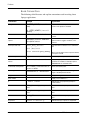
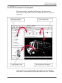
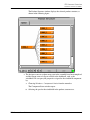
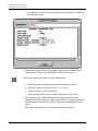
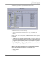
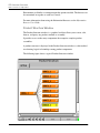
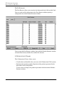
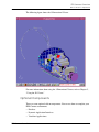
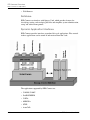

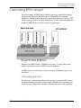
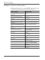
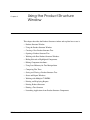
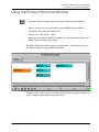
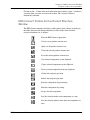
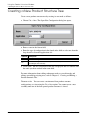
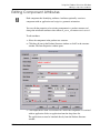
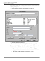
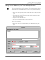
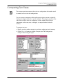

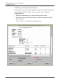
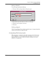
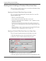
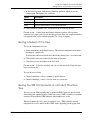
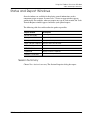
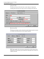
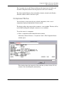


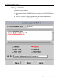
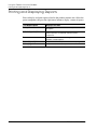
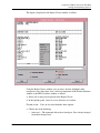
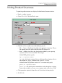
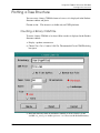
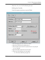
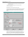
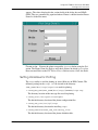
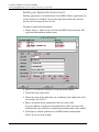
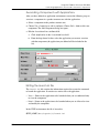
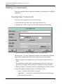
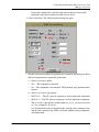
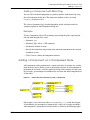
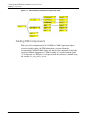

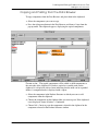
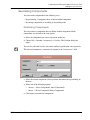
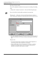

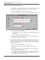
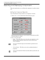
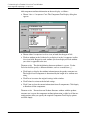

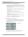
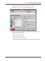
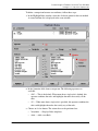
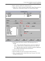
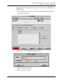

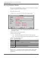
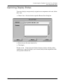
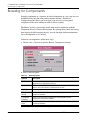
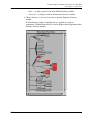
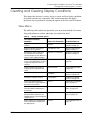
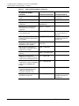
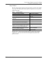

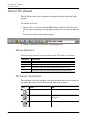
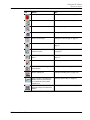
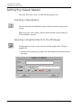
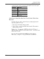
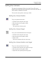
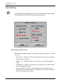
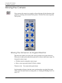
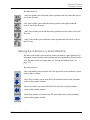

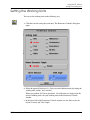

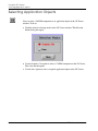
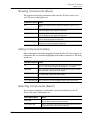
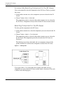
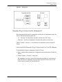
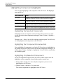


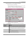
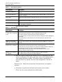


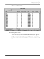
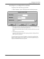
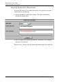
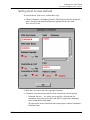

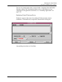
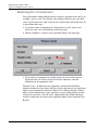
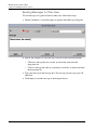
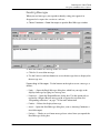
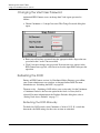
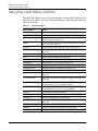
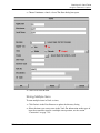
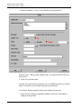
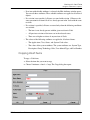
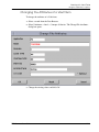
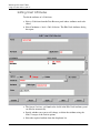
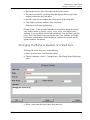
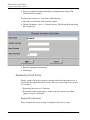
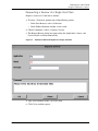
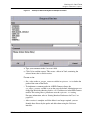
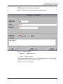
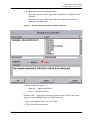
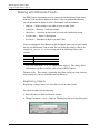
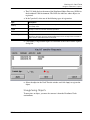
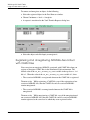
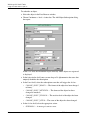
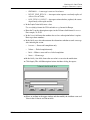
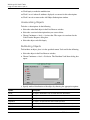
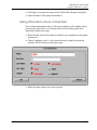
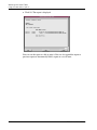
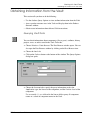
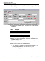
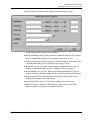
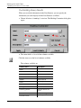
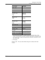
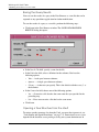
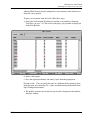
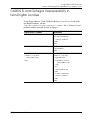
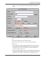

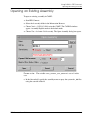
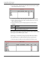
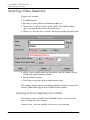

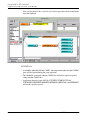

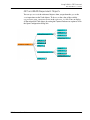
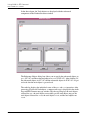
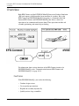

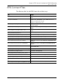
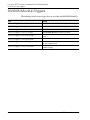

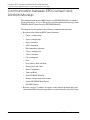


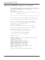
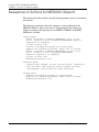


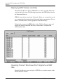
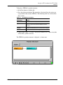
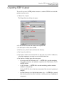
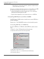
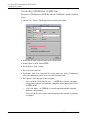


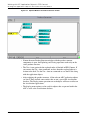
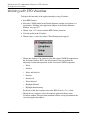
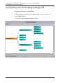
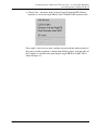
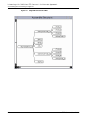
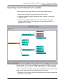


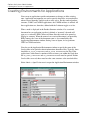

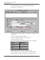

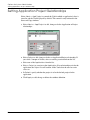
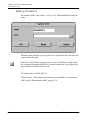
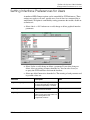


![[DvRELATIONS] - SyntaX Software Inh. Jörn Satow](http://vs1.manualzilla.com/store/data/006800015_1-13c0737460c05dc4e09174afe239eecd-150x150.png)