1
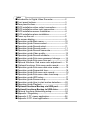
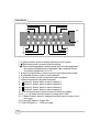
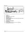
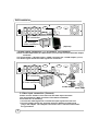
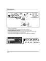
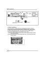
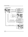
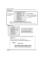
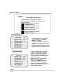
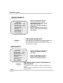
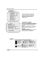
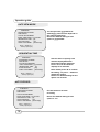
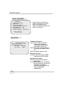
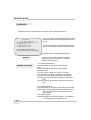
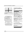
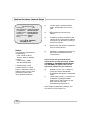
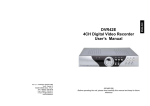
Digital Video Recorder
User’s Guide
4CH DVR
Index
Introduction to Digital Video Recorder------------------2
Front panel buttons-------------------------------------------3
Rear panel buttons ------------------------------------------4
DVR installation:video output connection--------------5
DVR installation:video input connection----------------5
DVR installation:sensor installation----------------------6
DVR installation:alarm installation------------------------7
Power up the unit --------------------------------------------8
On-screen display--------------------------------------------9
Operation guide:Main menu-------------------------------10
Operation guide:Camera select---------------------------10
Operation guide:Record select----------------------------11
Operation guide:Record mode----------------------------11
Operation guide:Record frame-rate----------------------12
Operation guide:Video quality-----------------------------12
Operation guide:Record schedule------------------------13
Operation guide:Sub menu-password change--------14
Operation guide:Sub menu-time set---------------------15
Optional functions :Sub menu-color adjustment----- 15
Optional functions :Sub menu-audio record---------- 15
Operation guide:Sub menu-date view mode-----------16
Operation guide:Sequential time--------------------------16
Operation guide:Sub menu-auto record-----------------16
Operation guide:Sub menu-video loss beep-----------17
Operation guide:HDD setup -------------------------------17
Operation guide:Sensor setup ----------------------------18
Operation guide:How to start motion detection-------20
Operation guide:Playback ----------------------------------21
Optional functions:Backup via USB port-----------22
Optional functions:Backup to USB drive-----------23
Optional functions:Networking setup--------------------24
Appendix I Regulatory --------------------------------------25
Appendix II PC viewer application-----------------------26
Appendix III PC client application------------------------28
Introduction
Introduction to Digital Video Recorder (DVR)
The digital video recorder (DVR) is for recording/retrieving video streams
from up to 4 channels at the same time. It adopts a digital image
compression technology to compress the input channel video streams,
and uses HDD to record the compressed video stream.
The following operation guide explains how to operate/manage the DVR,
and the following installation guide explains how to install DVR at your
home or HDD into the DVR.
Hope you enjoy it, use it to protect your home, and eventually make your
home as SAFE HOME.
2
Front Panel
4
5
3
2
6
7
1
16
17
8
9
10
11
15
14
13
12
1. (Menu) button: press to display Operation menu option
2. (Recording button): press to start recording.
3. (Stop recording/playback button):press stop recording/playback
(the authorized password is requested upon stopping record;
the default password is 111111)
4. (Fast forward button): press to play the recorded stream faster.
5. (Playback button): press to start playback
6. (Pause button): press to pause the video playback
7. Reverse:press to playback backward
8. Channel 1 button: press to select channel 1
9. Channel 2 button: press to select channel 2
10. Channel 3 button: press to select channel 3
11. Channel 4 button: press to select channel 4
12. All channels button: press to select all channels display
13,14. up down buttons: press to change menu field
15. (Select) button: press to change the setting value or enter into a
sub menu
16. Green LED light on :Power ON
17. Red LED light on: HDD recording
3
Rear Panel
13
3
4
12
1.
2.
3.
4.
5.
6.
7.
8.
9.
10.
11.
12.
13.
4
1
2
5
6
7
8 9
10
11
S Video
Video output
Monitor : Second Video output
Video input
Video loop-through
Sensor input/alarm output: 4 sensor inputs and one alarm output
NTSC/PAL switch
DC-in (12Voltage)
Audio-in/out (optional function)
LAN(RJ45) (optional function)
Power switch
PC Link : USB device (2.0) (optional function) or USB Host
VGA output (optional function)
DVR Installation
BNC connection
Or through
S-Video connection
(Optional)
1.Video output connection ( TV or monitor, LCD monitor)
Please connect TV(monitor) or LCD monitor (optional) to the unit over the Video output
connector.
The unit provides 1 x S-Video input, 2 x BNC connector and 1 x VGA output. (optional)
The above Figure shows the video signal line connection.
Signal Line
BNC connection
Or through
S-Video connection
Camera
Power line
AC/DC adaptor
power outlet
2. Video input connection ( Camera)
Please connect Camera to the unit over the Video input connector.
The unit provides 4 x BNC connectors.The camera installation
Procedures are as following:
i. Connect the video signal line: connect the video signal line to the unit
ii.Connect camera power line: Connect camera’s adaptor to camera, and
plug in the adaptor. The complete connection with a camera will be shown
as figure above:
5
DVR Installation
Signal Line
Sensor
Power line
AC/DC adaptor
power outlet
3.Sensor Installation
The unit provides 4 sensor input for 4 channels. The sensor
Installation procedures are as follows. There are two simple steps
For the installation of the sensors.
i. Connect the sensor signal line: Connect the video signal line to the unit. The
Sensor signal terminal is at the unit’s back panel
ii.Connect the sensor adaptor jack into the sensor, and plug in the adaptor.
CH1
6
CH2
CH3
CH4 Alarm out
DVR Installation
Signal Line
power outlet
AC/DC adaptor
Alarm
4. Alarm installation
The unit provides 1 internal switch for sounding alarm when the sensor is
Activated due to the unwanted entrance of anonymous visitor. The switch
Is open at normal state, but, when the alarm is activated, the switch is closed
So that the alarm gets the power. The circuitry is shown as above figure.
There are two simple steps for the installation of the alarm
i. Prepare the power supply:the alarm needs a power supply, the power supply
comes with the alarm
ii.Connect the alarm power line:the alarm power line is connected to the alarm
switch terminal.
7
Power up the unit
After the unit is properly installed, the unit is ready to record and play. Then
apply power and switch on.
After the unit is powered on, the
unit will check HDD for several
seconds,
The unit will enter into real-time
display mode shown as the right
figure:
8
HDD CHECKING ------OK
Master [xxxxxxx]
CH1 CH3
CH3 CH4
On-Screen Display
1. Power on the system
Press button to open OSD
menu as right
CH1 CH3
CH3 CH4
Press button to exit OSD
menu to real-time display
MAIN MENU
CAMERA SELECT
1234
RECORD SELECT
1234
RECORD MODE
QUAD
RECORD FRAMERATE 30
VIDEO QUALITY
HI
RECORD SCHEDULE
SUB MENU
HARD DRIVE SETUP
OSD Mode Display
Press button to start
recording
Press button to stop
recording( password is
requested!)
● CH1 ● CH3
● CH3 ● CH4
Recording Mode Display
Press button to search
time or event to playback
Press button to exit the menu
PLAY MENU
HDD: MASTER
04/03/24 13:24:21-04/03/24 13:44:54
>01 TIME 04/03/24 13:24:21
>02 TIME 04/03/24 13:30:55
>03 TIME 04/03/24 13:40:54
() MOVE,( ) CHANGE,()PLAY
SEARCH MODE
Press button
to start playing
Press button to stop playback
CH1 CH3
CH3 CH4
PLAYBACKMODE
9
Operation guide
MAIN MENU
MAIN MENU
CAMERA SELECT
1234
RECORD SELECT
1234
RECORD MODE
EACH
RECORD FRAMERATE 25
VIDEO QUALITY
HI
RECORD SCHEDULE
SUB MENU
HARD DRIVE SETUP
SENSOR SETUP
Move ()/Select ( )
Scene(<<)/Exit ()
Press to display
menu option shown
as right figure.
Operation Buttons
--- press to display menu option.
--- press to change menu field or
change the unit’s configuration values.
--- press to select menu item or
confirm the selection.
Please stop recording or playback before you enter into OSD menu.
You will be requested to enter password, while stopping recording.
The default password is “5555555”; please refer to the page for the definition of the keys
CAMERA SELECT
MAIN MENU
CAMERA SELECT
1234
RECORD SELECT
1234
RECORD MODE
EACH
RECORD FRAMERATE 25
VIDEO QUALITY
HI
RECORD SCHEDULE
SUB MENU
HARD DRIVE SETUP
SENSOR SETUP
Move ()/Select ( )
Scene(<<)/Exit ()
The unit provides 4 camera inputs.
You can use channel buttons on
the front panel to select specified
channel for real-time display.
Notice:The default setting for this
option is all of four cameras “ON”
You can use “ ” button or channel buttons for different combinations for
channel display.
Example:
1. When you choose (----), all cameras are off
2. When you choose (1234), all cameras are displayed.
3. When you choose (---4), only the fourth channel is displayed.
NOTICE
VIDEO LOSS !
“VIDEO LOSS” signal will be displayed, and the
built-in alarm buzzer will be triggered to sound,
while no video connection or connection failure.
10
Operation guide
NOTICE
Channel Display Control
In each mode( ) mode, you can use the
following buttons to display Full-screen format
of each channel.
Channel 1 button: Full screen
display of channel 1
Channel2 button: Full screen
display of channel 2
Channel 3 button: Full screen
display of channel 3
Channel 4 button: Full screen
display of channel 4
RECORD SELECT
MAIN MENU
CAMERA SELECT
1234
RECORD SELECT
1234
RECORD MODE
EACH
RECORD FRAMERATE 25
VIDEO QUALITY
HI
RECORD SCHEDULE
SUB MENU
HARD DRIVE SETUP
SENSOR SETUP
Move ()/Select ( )
Scene(<<)/Exit ()
RECORD MODE
MAIN MENU
CAMERA SELECT
1234
RECORD SELECT
1234
RECORD MODE
EACH
RECORD FRAMERATE 25
VIDEO QUALITY
HI
RECORD SCHEDULE
SUB MENU
HARD DRIVE SETUP
SENSOR SETUP
Move ()/Select ( )
Scene(<<)/Exit ()
11
Selecting channel on this menu
option is same as “CAMERA
SELECT” options.
Only selected camera will record
real-time events during recording
period
Notice:The default setting for this
option is all of four cameras “ON”
There are two kinds of recording
mode : (each mode; full screen
mode)& (quad screen mode).
when you set to mode, you can
view the full-screen display of one
specified channel.
When you set to mode, quadscreen will be displayed.
Please use buttons of front
panel to select mode and then
enter to confirm the selection
Notice:The default setting for this
option is EACH mode
Operation guide
RECORD FRAMRATE
MAIN MENU
CAMERA SELECT
1234
RECORD SELECT
1234
RECORD MODE
EACH
RECORD FRAMERATE 25
VIDEO QUALITY
HI
RECORD SCHEDULE
SUB MENU
HARD DRIVE SETUP
SENSOR SETUP
Move ()/Select ( )
Scene(<<)/Exit ()
There are 9 different frame rate
settings for operation: (NTSC
system:30fps,15fps,10fps,7fps,5fp
s,4fps,3fps,2fps,1fps;
PAL:25fps,12fps,8fps,6fps,4fps,3f
ps,2fps,1fps )
Notice:The default setting for this
option is 30pfs under NTSC, 25fps
under 25fps
RECORDING FRAME RATE
The higher the record frame rate is, the more natural look
will be displayed on the screen on playback mode.
But the lower the record frame rate is, the more you can
save the space on HDD.
NOTICE
VIDEO QUALITY
MAIN MENU
CAMERA SELECT
1234
RECORD SELECT
1234
RECORD MODE
EACH
RECORD FRAMERATE 25
VIDEO QUALITY
HI
RECORD SCHEDULE
SUB MENU
HARD DRIVE SETUP
SENSOR SETUP
Move ()/Select ( )
Scene(<<)/Exit ()
NOTICE
There are 3 different video quality
settings for operation: Normal,
Low, High
Please use buttons of front
panel to select mode and then
enter to confirm the selection
DIFFERENT VIDEO QUALITY SETTINGS ON
HDD CAPACITY
The higher the video quality is, the clearer images the unit
plays.
But the lower the video quality is, the more you can save the
space on HDD.
12
Operation guide
RECORD SCHEDULE
MAIN MENU
CAMERA SELECT
1234
RECORD SELECT
1234
RECORD MODE
EACH
RECORD FRAMERATE 25
VIDEO QUALITY
HI
RECORD SCHEDULE
SUB MENU
HARD DRIVE SETUP
SENSOR SETUP
Move ()/Select ( )
Scene(<<)/Exit ()
RECORD SCHEDULE
+TTTSSTTTTTTTTT+
0 3 6 9 12 15 18 21 24
T:Time S:Sensor -:None
Move ()/Select ( )
Scene(<<)/Exit ()
Enter into this option to change a
recording schedule during a day
(24-hour period) .
Numbers above indicate the time duration
of 24 hours.
(T) Letter indicates recording.
(S) Letter indicates sensor recording. It
means the unit starts recording as the
attached sensors being triggered during this
period.
(--) Recording is off during this duration.
SETTING EXAMPLE:
0:00 ~ 7:00 SENSOR RECORDING
7:00 ~11:00 RECORDING DISABLED
11:00 ~18:00 RECORDING
18:00 ~24:00 SENSOR RECORDING
+SSSSSS----T T T T T T T S S S S S S +
:
:
:
:
:
0
6
11
18
24
13
Operation guide
SUB MENU
MAIN MENU
CAMERA SELECT
1234
RECORD SELECT
1234
RECORD MODE
EACH
RECORD FRAMERATE 25
VIDEO QUALITY
HI
RECORD SCHEDULE
SUB MENU
HARD DRIVE SETUP
SENSOR SETUP
Move ()/Select ( )
Scene(<<)/Exit ()
SUB MENU
PASSWORD CHANGE
TIME SETUP
COLOR ADJUSTMENT
DATE VIEW MODE yyyy/mm/dd
SEQUENTIAL TIME [2]
AUTO RECORD
[on]
VIDEO LOSS BEEP [short beep]
Move ()/Select ( )
Scene(<<)/Exit ()
NOTICE
Enter into this option to change
password, time /date setting, date
format and enable the connection
between the unit and PC over
USB interface.
PASSWORD CHANGE .
You enter into “PASSWORD CHANGE”, a
password change input menu replaces the
“SUB MENU” (The default password is
111111)
When the new password is accepted, the
board will flash the following screen
message:
PASSWORD changed!!!
The message will blink 3 times. Then the
display goes back to SUB MENU.
FRONT PANEL BUTTONS DEFINITION
means “1”
means “5” means“b”
means “2”
means “6” means “C”
means “3”
means “7” means “D”
means “8” means “E”
means “4” means “9” means “F”
means “0”
14
Operation guide
TIME SET
TIME SETUP
2004/03/21 03:23:21
Enter into this option to change
date and hour.
Move ()/Select ( )
Scene(<<)/Exit ()
COLOR ADJUSTMENT
COLOR ADJUSTMENT
brightness contrast
Channel-1 [6]
[ 4]
Channel-2 [6]
[ 4]
Channel-3 [6]
[ 4]
Channel-4 [6]
[ 4]
Use this menu to adjust each
camera’s brightness and contrast
Notice:The default setting for this
option is 6 under brightness; 4
under contrast for all of four
cameras
BRIGHTNESS (<<)/Contrast(>>)/SELECT ( )
Move () /Exit ()
AUDIO RECORD
AUDIO RECORD
[ON]
Use this menu to either turn on
audio recording or off
”AUDIO RECORD” is optional
function which is only provided with
LAN model.
AUDIO MUTE
AUDIO MUTE
15
[ON]
Use this menu to either turn on
sounding or off
Operation guide
DATE VIEW MODE
SUB MENU
PASSWORD CHANGE
TIME SETUP
COLOR ADJUSTMENT
DATE VIEW MODE yyyy/mm/dd
SEQUENTIAL TIME [2]
AUTO RECORD
[on]
VIDEO LOSS BEEP [short beep]
The unit provides yyyy/mm/dd or
dd/mm/yyyy variant which depends on
the regional preference.
Notice:The default setting for this
option is yyyy/mm/dd
Move ()/Select ( )
Scene(<<)/Exit ()
SEQUENTIAL TIME
SUB MENU
PASSWORD CHANGE
TIME SETUP
COLOR ADJUSTMENT
DATE VIEW MODE yyyy/mm/dd
SEQUENTIAL TIME
[2]
AUTO RECORD
[on]
VIDEO LOSS BEEP [short beep]
Move ()/Select ( )
Scene(<<)/Exit ()
Use this menu to specify each
channel display dwell time.
Dwell time settings determine
from 1 sec to 9 sec between
displays for 4 channels.
Note: Please press “
” to confirm
the setting. Or press” “button to
disable the setting.
Notice:The default setting for this
option is 2 seconds
AUTO RECORD
SUB MENU
PASSWORD CHANGE
TIME SETUP
COLOR ADJUSTMENT
DATE VIEW MODE yyyy/mm/dd
SEQUENTIAL TIME [2]
AUTO RECORD
[on]
VIDEO LOSS BEEP [short beep]
Move ()/Select ( )
Scene(<<)/Exit ()
16
Use this menu to run auto
recording
Notice:The default setting for this
option is “on”
Operation guide
VIDEO LOSS BEEP
SUB MENU
PASSWORD CHANGE
TIME SETUP
COLOR ADJUSTMENT
DATE VIEW MODE yyyy/mm/dd
SEQUENTIAL TIME [2]
AUTO RECORD
[on]
VIDEO LOSS BEEP
[short beep]
Use this menu to either select
buzzer’s ton(long tone or short
tone) or turn off the sound.
Notice:The default setting for this
option is short beep
Move ()/Select ( )
Scene(<<)/Exit ()
HDD SETUP
HARD DRIVE SETUP
OVERWRITE ENABLED [YES]
MASTER HDD FORMAT
HDD SIZE
82398MB
HDD USED
0MB 0%
OVERWRITE ENABLED:
If you choose “YES”, the unit will
continue recording and
overwrite the recorded data
when HDD’s space is full
If you choose “NO”, the unit will stop
recording while HDD’s space is
full
Notice: the default setting is “yes”
MASTER HDD USED:
It indicates how percentage of HDD’s
capacity has been occupied.
MASTER HDD FORMAT:
It erases all of the recorded data in
Master HDD
The authorized password is requested
before formatting, after the unit
formatted, the following
information will appear on the
screen “HARD DISK
FORMATTED” .
17
Operation guide
SENSOR SETUP
SENSOR SETUP
SENSOR RECORD TIME
ALARM OUT TIME
SENSOR RECORD TIME:
10
OFF
H/W DETECTOR SETUP
S/W DETECTOR SETUP
Move ()/Select ( )
Scene(<<)/Exit ()
Recording duration once sensor
Being triggered; the selection of the
duration is 5,10,15,20,25,30 secs
Notice: the default sensor recording time
is 10secs
ALARM OUT TIME:
It controls how long ( in second)
the alarm sounds after being triggered.
The settings are
Nonstop/off/5,10,15,20,25,30secs
Notice:the default setting is “off”
H/W SENSOR SETUP
CHANNEL-1 TYPE: NOT INSTALLED
CHANNEL-2 TYPE: NOT INSTALLED
CHANNEL-3 TYPE:NOT INSTALLED
CHANNEL-4 TYPE:NOT INSTALLED
Move ()/Select ( )
Scene(<<)/Exit ()
H/W SENSOR SETUP
The unit provides 3 different modes for
External sensor facilities
:
1.Not installed. 2. Normal open.
3. Normal close.
In normal open mode, the cable line
Connected between the sensor and
the unit is cut off by an intruder, the unit
starts recording.
In normal close mode, the cable line
connected between the sensor and the
Unit is cut off by an intruder , the unit
stops recording
Notice: the default setting is Not installed
18
Operation guide
S/W DETECTOR SETUP
CHANNEL-1
CHANNEL-2
CHANNEL-3
CHANNEL-4
1:MORE
SENSITIVITY 5
SENSITIVITY 5
SENSITIVITY 5
SENSITIVITY 5
- 9:LESS
Move ()/Select ( )
Scene(<<)/Exit ()
19
MOTION SENSITIVE SETUP
Use this menu to adjust the sensitivity of
each channel.
( 0 stands for highest
Sensitivity, but 9 is for lowest
sensitivity.) .
Notice: the default sensitivity level is 5
Operation guide
How to operate Motion detection recording
SENSOR SETUP
SENSOR RECORD TIME
ALARM OUT TIME
10
OFF
H/W DETECTOR SETUP
S/W DETECTOR SETUP
Move ()/Select ( )
Scene(<<)/Exit ()
S/W DETECTOR SETUP
CHANNEL-1
CHANNEL-2
CHANNEL-3
CHANNEL-4
SENSITIVITY
SENSITIVITY
SENSITIVITY
SENSITIVITY
5
5
5
5
Move ()/Select ( )
Scene(<<)/Exit ()
SCHEDULE RECORD
+TTTSSTTTTTTTTT+
0 3 6 9 12 15 18 21 24
Move ()/Select ( )
Scene(<<)/Exit ()
20
Follow the steps as below to
activate motion-detection
recording.
1.Please set the period of
Alarm out time
2.Please go to S/W
DETECTOR SETUP under
“SENSOR SETUP” menu as
the left figure shown.
3. Specify the sensitivity of
each channel.
4. After the selection, please
be back to MAIN MENU and
go to “SCHEDULE RECORD”
to power on the alarm setting.
Notice: The setting under
“Record Schedule” is
necessary for starting the
operation of motion detection
recording.
Operation guide
PLAYBACK
Please use the front panel buttons to operate various playback functions.
PLAY MENU
HDD DRIVE: MASTER
04/03/2006 13:24:21-04//03/2006 13:44:54
>01 TIME 04/03/24 13:24:21
>02 TIME 04/03/24 13:30:55
>03 TIME 04/03/24 13:40:54
Press “” button, then the playback time /events
selection menu as the left figure appears on the
screen.
You can either enter the specified time/date to
playback or select the event to search the video
Move ()/Play (>)/Exit Menu()
Scene(<<)/Select Mode (>>)/Next Page( )
1. Please stop recording before playback.
NOTICE
CONTROL BUTTONS
2. Because the events selection is default
setting, so you need to press “” button to
switch to time selection.
1. (fast forward button):
Press this button to play the recorded stream
faster.
The unit provides three levels of fast forward
playback speed:
1: play one time faster (x1), press “” button
2: play two times faster (x2) than the normal play
3: play four times faster (x4) than the normal play
4: play thirty-two times faster (x32) than the normal
play
5: play sixty-four times faster (x64) than the normal
play
2. (reverse button):
Press this button to play the recorded stream backward.
Remarks: the reverse playback speed depends on the
fps, the number of the recorded channel, the
video quality.
3. (pause button) :
Press this button to pause the playback, or to advance
one single frame upon pause mode.
21
Optional functions:Backup via USB port
The unit provides one USB port to
simple backup over the connection with
PC. Please mind the following steps to
successful link.
Step 1. Connect the USB cable between
the unit and PC
Step 2. Select “LINK TO PC” under
submenu of the unit
Step3. The “linking” will take around
30sec.
Step4. The connection is ready for PC
backup as “Linked” indicates on the
screen.
Step 5. Open the PC viewer on PC, once
PC identifies one unknown Hardware
device
Step6. Press”Menu” button back to
“Main Menu”
Warning:.Please don’t press
“MENU” button during linking
status, it would likely lead to
unpredictable Error on your PC
REMARKS: Please refer to Page.26 for
the PC viewer installation and operation
guide.
22
Notice: 1.the unit employs USB 2.O, so
it will take around 5 min to hand shake
with USB 1.0.
2. Before operating backup over USB,
please install PC viewer software into
your PC.
Optional functions:Backup on USB drive
1
2
3
4
USB device ready!
Notice: Please stop recording before
your backup!
SEARCH TIME
HDD: MASTER
04/03/24 13:24:21-04/03/24 13:44:54
>01 TIME 04/03/24 13:24:21
>02 TIME 04/03/24 13:30:55
>03 TIME 04/03/24 13:40:54
() MOVE,() BACKUP,(EXIT
()SELECT MODE ( ) CHANGE
PERIOD
The unit provides one USB Host
port(optional) to simple backup data
on Pen drive. Please follow the steps
below:
Before doing backup to USB pen drive,
please stop recording!
Step 1. Connect the USB pen drive to
DVR, then “USB device ready “ will be
on the screen.
Step 2. press “
” button to start
backup function, and then follow all the
instructions on the screen.
Notice: please press”” to format
USB pen drive on request. After the
format, please press “
” button again
to enter into “SEARCH TIME” menu.
Step3. Either select one period of time
or specify the event you want to backup
to USB pen drive.
Notice: press press “” button to
switch between the time selection and
event selection!
Step 4. After the selection, please enter
“” to confirm the backup.
0000 SECONDS
() MOVE,() BACKUP,(EXIT
()SELECT MODE ( ) CHANGE
Step 5. Please enter the time for the
data you will backup to USB pen drive.
Step6. Press” ” button to confirm and
start the backup!
Step7. After the backup, please install
PC viewer software into your PC .
23
Optional functions: Network Setup
NETWORK SETUP
ACCEPT IP
YES
MAC ADDRESS 03:01:01:01:25:46
IP ADDRESS
192.168.000.090
SUBNET MASK 255,255,255,000
GATEWAY
192.168.000.001
DVR ID ON LAN A PLUS
DHCP
[OFF]
PRESS (),
THEN
PRESS(
) TO EXIT
1)
The first option “enabled network
client”, please make sure is set to
YES
2)
MAC setting will not need to be
altered.
3)
*IP address (a static IP address ) will
need to be set to the DVR IP address
you planning to allocate to, while you
connect to Internet.
4)
Subnet mask will need to be obtained
from the routing device.
5)
#Gateway IP address (IP address A)
will need to be obtained from the
routing device.
(
)
Notice:
1.PC Minimum requirements
of Networking :
CPU: 1 GHZ or above
System Memory: 256MB
or above
VGA memory: 32MB
OS: Window2000/XP
2. Please assign 14337,
14338 to the Port to install
DVR in a LAN with a static IP
address under a router ( with
firewall) for sharing with
other equipments like PC.
Please check with your M.I.S staff or
administrator to enter the setting of MAC
ADDRESS, IP ADDRESS,SUBNET MASK
and GATEWAY Or please refer the left
figure as a example for your reference
6)
7)
DVR ID on LAN : use “ ” button to
specify the DVR’s identification.
26 alphabets will appear in sequential
order.
DHCP [ON] : press” ” to confirm the
installation as [ON].(the default
setting :OFF), and re-power on the
DVR. Then the DVR will
automatically get dynamic IP.
After configuring Networking settings, you
Can start to remote monitor via
24
Appendix I.
Regulatory
FCC Certification
This equipment has been tested and found to comply with the limits for
a class A digital device, pursuant to Part 15 of the FCC rules. These
limits are designed to provide reasonable protection against harmful
interference when the equipment is operated in a commercial
environment. This equipment generates, uses, and can radiate radio
frequency energy and, if not installed and used in accordance with the
instruction manual, may cause harmful interference to radio
communications. Operation of this equipment in a residential area is
likely to cause harmful interference in which case the user will be
required to correct the interference a the own expense.
CE Mark
This product is marked with the CE symbol and indicates compliance
with all applicable directives.
25
Appendix II: PC Viewer (HOST backup)application
Note: Before installing PC viewer into your PC, please make sure
DirectX9.0 or above, and the updated version of Service pack!!!
Data capture
AVI conversion
This PC viewer is applied for searching a period of data from Hard DISK or for the data of
USB pen drive
Please follow the steps below to complete the installation of pc viewer:
1.
Please install USB pen drive into your pc
2.
Please install PC viewer software into your PC (This software currently
supports Windows2000 and Windows XP!) and enter into the software, then
you will see a dialog box as above( figure 1) appear on the screen.
3.
Please right click on the mouse to enter “ Open disk “ to either search the
data from the Hard Disk or from the USB pen drive
26
Appendix II: PC Viewer application
For viewing the data
from USB pen drive
4. After selecting “Open file”, the above dialog box will pop up
a. please enter into Disk1 for viewing the data of USB pen drive
b. please enter into Disk0 for searching data from Hard disk
27
Appendix IV: PC Client Application.
This dedicated remote PC client software allows you
from a remote location to view live and recorded video over
Internet. Also, you can capture,convert the video from the unit
into AVI file or JPEG file, or play the stored video later on.
Please follow the instructions below to use PC client.
After you install PC client software into your PC, the Main
window will appear on screen:
Main Window of PC client software
28
Appendix IV: PC Client Application.
1.
How to connect to the DVR
click on “Connect” option on Main window
Click on “Connect “ to enter into
“DVR Client connection manager”
As the following dialog window:
1.
2.
3.
29
DVR IP: The DVR IP address is the IP address of the
remote DVR.
Password : The password is same password used for
formatting the DVR’s Hard Drive. The default value is
111111
Nickname: If you have configured DHCP settings in DVR,
you can connect to DVR by click on “Search DVR”.
There will be a list of DVR in Nickname list box. Select
one you want to connect with from the list.
click on “OK” to create connection.
Appendix IV: PC Client Application.
2. Connection Status:
When successfully connected, you would see” Connected”
sign. This window also displays DVR IP address and shows
changes of connection speed.
• To disconnect, simply click “ Disconnect “
• To close the application, click “ Close Window” button
30
Appendix IV: PC Client Application.
3. DVR control
The panel shown as the following figure operates exactly
as the remote DVR operational button allow you to control
remote DVR to live view, record and playback as well.
31
Appendix IV: PC Client Application.
4. Capture & Playback on you PC
4-1 Capture video data
When you click “REC” button, it will
start to record the incoming video
on your PC hard disk. The DVR
client creates “ steam_files”folder
where the execution file is located.
When the client is recording, the
Capture & Play status indicator
would show the current status, REC.
4-2 Playback
After recording is finished, click”
Play” button to play the recorded
video stream. Then you will see a
stream file list of the video stream
files previously captured.
32
Appendix IV: PC Client Application.
5. DVR management
This option enables you to adjust remote DVR’s operation setting :
Video Quality, Record Frame rate, Alarm On Duration, Alarm record
Duration, Input Channels, Record Channels, DVR system time setting
and Record Schedule. All of settings operate as you do with DVR itself.
Notice: For the record mode change can be made only on DVR, so the
display shows the current DVR record mode on connection.
33
Appendix IV: PC Client Application.
6. AVI file
Click on this button to convert the real-time
video data or the recorded data into AVI file
Click on “ AVI save as” button to convert the desirable data into AVI file,
then you will see the following dialog box for saving the AVI file. After
specifying the file name and confirmation, please click on “ Backup to
AVI” to start the conversion.
34
Appendix IV: PC Client Application.
8. Single Channel Scaler
Single channel scaler is effective only in single channel mode. If you are
viewing single channel, you can scale it up/down by selecting these
options.
35
Appendix IV
The following is the recording time vs video quality
settings table for your reference
1
2
3
4
5
7
10
15
30
HI
897H
448
H
299
H
223
H
179
H
104
H
89H
59H
29H
NORMA
L
1092
H
546
H
364
H
273
H
218
H
152
H
109
H
72H
36H
LO
1365
H
682
H
455
H
340
H
273
H
191
H
136
H
91H
45H
HI
690H
345
H
230
H
172
H
138
H
96H
69H
46H
23H
NORMA
L
840H
420
H
280
H
210
H
168
H
117
H
84H
56H
28H
LO
1050
7H
525
H
350
H
262
H
210
H
147
H
105
H
70H
35H
Frame/Second
MODE
MODE
NTSC format
1
2
3
4
6
8
12
25
HI
448
H
299
H
223
H
179
H
104
H
89H
59H
29H
NORMA
L
546
H
364
H
273
H
218
H
152
H
109
H
72H
36H
LO
682
H
455
H
340
H
273
H
191
H
136
H
91H
45H
HI
345
H
230
H
172
H
138
H
96H
69H
46H
23H
NORMA
L
420
H
280
H
210
H
168
H
117
H
84H
56H
28H
LO
525
H
350
H
262
H
210
H
147
H
105
H
70H
35H
Frame/Second
MODE
MODE
PAL format
PS: The recording hours on 80GB HDD
36