1
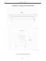
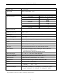
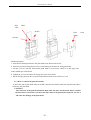
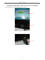
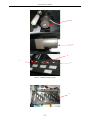
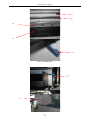
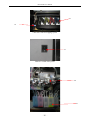
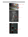
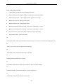
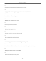
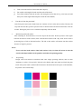
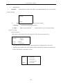
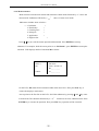
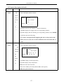
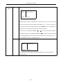
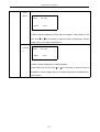
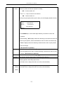
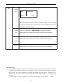
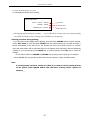
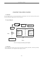
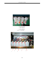
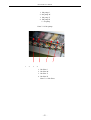
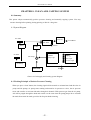
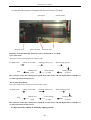
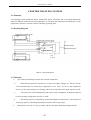
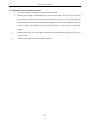
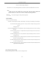
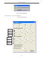
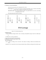
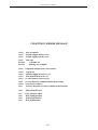
User’s Manual <EN> FINA320B 600001810 Version 1.0 FINA320B User’s Manual Thank you very much for purchasing our printer ◆ In order to use this printer correctly and safely and understand this product’s capability, please read this manual carefully. ◆ The manual includes equipment structure, description, technical parameters, operation manual, safety information and application of software, etc. ◆ This manual is subject to change without notice. ◆ Contents here in contained are believed to be correct, however, please contact us if you find any error or something not clear enough. September, 2007 Version 1.0 2 FINA320B User’s Manual INDEX Clean Post...........................................................................................................................................................28 -2 - FINA320B User’s Manual Chapter 1 Safety information Before use your FINA320B Digital Printer ( Hereafter refer to printer ) , please read following safety information. Pay attention to the cautions on the Printer. 1.1 Important Safety Information • • • • • • • • • • Do not block the hole on the cover. Do not insert any object into the Printer groove. Don’t let any kind of liquid splash into Printer. Only use the power supply according to the label. You may choose either AC 110V or 220V for different countries and regions. Connect all the equipment to a properly grounded socket. Avoid the socket in the same circuit with copy machine or air conditioner. Avoid to using the socket controlled by the wall switch or by auto timer. Please keep Printer away from the latent source of electromagnetic disturbance. For example, loudspeaker or wireless phone. If you use additional cable, please make sure that total amperage of the equipment connecting with cable shall not exceed the amperage of the power supply. Moreover, the amperage of all equipment connecting with wall socket does not exceed the amperage of the wall socket. Do not use damaged Electrical Power wire. Do not repair Printer by yourself. Shut off the power and ask experienced technician for help, if the following situations occur: Power cable or plug is damaged. Liquid splashes into printer. Printer falls down or broken. Printer cannot work properly or change in property. 1.2 Caution When Using Printer • • • Don’t use your hand to move print head; otherwise the printer will be damaged. Always use power switch to turn On/off the printer. Before shutting down the Printer, do not pull out Power Supply wire or Data Wire. Before moving the printer, please make sure the print head is fixed at original position. 1.3 Guide When Using Ink Cartridge • • • • Keep ink away from children. Do not let the children drink or touch. If ink spills on the skin, please wash with soap and water. If ink splashes into eye, please wash with water immediately Do not shake the ink cartridge in case ink leak is caused. Please keep surrounding clean when you replace a new ink container. It helps you improve printing quality. 1.4 Choosing Printer Installation Place • • Put printer at a horizontal and stable place with enough space; otherwise, the Printer may not work properly. Don’t leave Printer at a place where temperature and humidity change severely. Avoid direct sunlight, strong light or heat. -4 - FINA320B User’s Manual • • • Avoid shaking or vibrating. Keep sufficient room around printer for air circulation. Place printer nearby the wall socket, so that it is easy to connect or disconnect the power supply. 1.5Warning, Caution and Attention • • • Warning Must obey in order to ensure personal safety. Caution Must obey in order to protect the machine. Attention Contain some important and useful information about operation. -5 - FINA320B User’s Manual CHAPTER 2 TECHNICAL PARAMETERS Chart 2-1 Printer Outlook and dimension -6 - FINA320B User’s Manual Product Mode Print Head Drop size FINA320B Xaar 130/600 DPI 8/12/16 30pl Print Mode 360x360 Speed and output Output(㎡/h) (Mode: High) 62 360x720 39.74 360x1080 20.65 720x720 15.48 720x1080 10.32 720x1440 7.74 Max Media Width 3300 mm Media Transmission Media type Auto Media Feeding & Take-up system(Take-up is OPTIONAL), «50kg/Roll PVC, Flex, Vinyl,l window film,polyester, etc Max Printing Width 3250 mm Media Feeding Auto Media Feeding & Take-up system(Take-up is OPTIONAL) Color 4color Display LCD display with 8 key panel, self-diagnosis available Ink Type Eco-solvent and Solvent-base ink, main ink tank volume Main features Auto Media heating(Pre-heater, middle plate heater, P/H heater Infrared Drier (OPTIONAL) Auto Print-heads Cleaning and Capping system Print head Height 2.5 mm-4.5 mm above media adjustable Operation Platforms Multi-operation platforms (Window2000, XP, etc.) Print Interface USB2.0 interface (Window2000、NT、XP etc) Printer Drive Normal FINA RIP, support multiform third-party RIP Power AC100 或 240V,50HZ/60HZ Working Environment Temperature:20°C ~ 28°C Humidity : 40% ~ 70% Printer Size/Weight Net Weight: 3900mm(L) X 870mm(W) X 1100mm(H) 330KG Gross: 4500mm(L) X 925mm(W) X 1200mm(H) 368KG 1040 The parameters above are subject to change without notice. -7 - FINA320B User’s Manual CHAPTER 3 EQUIPMENT ASSEMBLY AND ADJUSTMENT 3.1 Assemble Printer 3.1.1 How to install the dry blower assy 7 -8 - FINA320B User’s Manual 3.1.2 How to install the print head -9 - FINA320B User’s Manual Print Head cable In tube Print head clamp Out tube Method and Steps: a. Insert Xaar130/600 print head to the print head frame downwards at first. b. Insert the print head fixing dowel to the corresponding dowel hole for fixing print head. c. Put the 2 screws with the Xaar130/600 print head on screw holes, which is on the upper and nether middle part of the frame. d. Tighten the 2 screws and draw the fixing dowel out of the frame. e. Put the sheeting between the two print head and fixed with screws which is 2.5*10 3.1.3 How to connect the print head cable 1. Insert one end of print head cable on the PH control board, and the other end of print head cable is inserted to the print head. CAUTION: The connector of the print head and the data cable only have one direction, Please confirm the direction is true before you insert the date cable to the print head connector. Or else it will cause the damage of the print head. - 10 - FINA320B User’s Manual Please connect all of the 8 print head cable based on the right picture Chart 3-3 Connection of print head cable - 11 - FINA320B User’s Manual 3.2 Attention before Turning on the printer 1. In order to clean print head easily, please prepare following items: • Flush solution • Non-woven fabric. 2. In order to inspect temperature and humidity of printing environment, please prepare relative measurers. Requirement for environment: Temperature: 20°C - 30°C • Humidity: 40% - 80% • 3. Power supply You may select AC 110V or 220V for different countries or regions. • Control power supply: AC 100 - 240V 50/60HZ • 50/60HZ (AC 100 V optional) • Heating power supply: AC 100 OR 240V 50/60HZ (AC 100 V optional) • Feeding power supply: AC 100 OR 240V Please choose the type of power shown on the printer in case of damage to the printer. • Make sure the printer is well grounded. • It is better to use UPS stable-voltage power. • 4. Requirement for computer In order to avoid problems caused by computer, please choose high quality computer or brand computer such as DELL or IBM, etc. 3.3 Port of Printer USB 2.0 Installation: Connect printer’s USB and computer’s USB directly. Find driver for USB at USB Instal File/Try Setup under printer’s driver. 3.4 Connect With Power 1. After all the parts installed, move printer to its working area and clean up the package. 2. Connect power cables, including power for printer and heater, printing data cable. Protective switch only works for heater’s power. Usually this switch should be at status of On (switch on above, far from red point). 3. After finishing, turn on power. The Auto-ink-supply-system runs to pump ink from main ink tanks to Sub ink tanks. 4. Feed in media and printer enters waiting status. 5. Then go in test printing. Observe ink drop. If not good, clean print head again. - 12 - FINA320B User’s Manual CHAPTER 4 EQUIPMENT STRUCTURE AND ACCESSORIES The main components charts of FINA320B Printer list as below: 1 2 Chart 4-1 Control interface and Infrared Drier 3 - 13 - FINA320B User’s Manual 4 5 8 7 6 Chart 4-2 Media feeding system 9 - 14 - FINA320B User’s Manual 10 11 12 13 14 Chart 4-3 Middle plate 15 16 - 15 - FINA320B User’s Manual 17 18 Chart 4-4 Clean and capping system 19 Chart 4-5 switch of the printe 20 21 - 16 - FINA320B User’s Manual 22 23 24 Chart 4-6 Pumps and Pipeline 26 27 25 28 Chart 4-7 Print Interface - 17 - FINA320B User’s Manual Parts on the printer include: 1. Control Panel: Set up and execute function and mode 2. Infrared Drier(Overseas option fittings): expedite the print media drying 3. Media take-up sensor : control the media take up motor run or stop 4. Media take-up motor: Take-up Roller driver 5. Media feeding motor: Feeding Roller driver 6. Media auto/manually feeding switch: switch auto to manually, or reverse 7. Media auto/manually take up switch: switch auto to manually, or reverse 8. Direction switch: Control the CW/CCW direction for media feeding. 9. Print Head localizer: fix the Print Head 10. Y-raster strip: Take count of print head horizontal moving, so as to insure of Y-direction image precision. 11. Y drive strap: Drive print carriage horizontal moving 12. Pinch Roller: Press media and make media smoothly 13. Printing Platform: Platform for printing 14. Press Roller Control Pole: Control press roller up / down for media feeding 15. Flash Plate handle: Control the flash plate up or down position. 16. Clean roller: Clean the print head for auto clean - 18 - FINA320B User’s Manual 17. Capping assy: Keep the print head wet when not use the printer 18. Capping handle: Control capping assy up / down for keep the print head wet. 19. Power Switch: Turn on/off printer 20. Manually Valve: Control the route switch 21. Sub-tank: provide ink to print head. 22. Ink filter: Filter impurity in ink 23. Ink pump: provide ink from main tank to sub tank. 24. Valve: Automatically control the air route 25. Current leakage protector: Prevent electric leakage of heating board 26. Printer Interface: USB2.0 interface provide the data communication to printer and computer. 27. Heating Power Socket: Provide power for heater 28. Power Socket: Provide power for printer - 19 - FINA320B User’s Manual - 20 - FINA320B User’s Manual CHAPTER 5 USAGE AND MAINTAINS OF PRINT HEAD 5.1 Usage of Print head 2 5 4 3 1 1— Print head 2— In tube 3— Out tube 4— Ink tube cap 5— Fitting Chart 5-1 Print head 1、 Flush humectants out of print head To moisturize print head, lots of humectants are injected into the head before it is used. The humectants must be flushed out for the first using. Before fix the head on the print head frame, do the steps as follows: Joint a filter on the In-tube of the head, and then joint an injector--which fills with flush solution--on the filter. Inject 10-20 ml flush solution to the head to eject the humectants inside. Then fill the head with flush solution to dissolve the humectants completely within 5-10 minutes. Finally, flush the head with about 30ml flush solution to eliminate the humectants completely. Make sure to operate on a stable and clean platform. Cautions: a) Clean platform for convenient operation; b) Don’t touch the surface of head and socket with hand; c) Clean the filter with flush solution; d) Connect a tube on the exit of the head to prevent ink flowing into the socket; - 21 - FINA320B User’s Manual e) Don’t touch the surface of head with other objects; f) Be careful to distinguish In tube and Out tube of the head; g) Eject flush solution from the nozzles with strength no more than 0.3 kg. (It is better to hold the injector with single hand and push it with the same thumb.) 2、 Extrude air from the print head” After fixing the head on the head frame (be cautious of the in tube and out tube). Remove the Cap from the Out tube; positive-pressure clean to fill the head with ink till ink streams out from nozzles. During the process air is extruded completely from the head. 3、 Moisturize print head surface After extruding air from the head, cover the Cap on the Out tube. Positive-pressure clean again until ink streams out of the nozzles, then scrub the head surface with a dry clean stick to form a protecting layer of ink on the head surface. The ink on the surface will stream into the nozzles because of negative pressure. Notes: Never scrub the head surface when head surface is dry, for that will orient air into the nozzles and shape bubbles in the pipelines and affect the printing quality. 4、 Test printing Design some color blocks as 20x20cm with some image operating software, and set color luminance as 100%, 50% and 10%. Print the color blocks under test mode and check the print result. If the print result is normal which means no ink-break and no ink spots on the mediums, the printer can work normally. - 22 - FINA320B User’s Manual Chart 5-2 color blocks for test printing 5.2 Maintenance of Print head 1. Ink replacing Flush the print head with the original ink first, and then flush it again with new flush solution, which matches the new ink. 2. Print head cleaning If low quality printing takes place, a positive-pressure cleaning is proper for the head. After positive pressure cleaning, scrub the head surface with a dry clean stick to stop ink streaming from the nozzles. Be sure not to use a stick with flush solution to scrub the head surface, otherwise, the flush solution will be siphoned into the nozzles. 3. Moisturize print head Use wet keeping frame to moisturize the head if the printers is left unused. The print head moisturizing method of this printer displays as follows: adhere a clean non-woven fabric with some flush solution on the print head and wrap it with a fresh keeping polyester film. - 23 - FINA320B User’s Manual CHAPTER 6 BASIC PANEL OPERATION 6.1 Menu Structure of Control Panel 1 33 2 1—LCD 2-- Function Keys 3--Direction Keys Chart 6-1 Control Panel 6.1.1 Function description of the keys 1 、 1 ) 2 ) Direction keys Operation via control panel : key : Scroll the menus for selection ; reduce or increase the values on LCD. key : Move the cursor position over the number string on LCD. When the printer is waiting : key: Move the media forward and backward ; key: Move the p/h carriage to cleaning position for cleaning and move it back to original position after cleaning. - 24 - FINA320B User’s Manual 2 、 Function keys 1) ONLINE : Switch the printer online and offline / press down and hold it for several seconds to pause printing. Waiting… Online ESC : Cancel operation and return to up-level menu 。 2) 3) ENTER : 4) FUNC : Confirm and execute the operation 。 Shift to special function ; Combine with key to test print when the printer is waiting. 3. Basic operation After power on the printer, the system executes X and Y motion test and p/h test. Booting >System >Y Motor V1.20 >X Motor Check —>Print head After self-test, the system moves the p/h carriage back to original position. The LCD displays printer model and version number and then shift to basic operation menu shown as below. That stands for the printer is ready. Menu Offline 1. Ink Status + 2. Heat Status + 3. Cleaning Tool + 4. Print para + - 25 - FINA320B User’s Manual 6.1.2 Menu structure Menu structure includes main menus and sub menus. Main menus followed by “+”s have sub menus inside. Submenus followed by “ -” s have no lower level inside. Main menu includes items as below : —> 1. Ink Status 2. Heat Status 3. Cleaning Tool 4. Print para 5. Application 6. Engineer Set + + + + + + Press key to scroll the menus upward and downward. Press ENTER to unwrap submenus. For example, while the arrow points to “1. Ink Status”, press ENTER to unwrap the submenu. LCD displays details of submenu M1 as below: Menu → M1 Offline Ink Status Ch A C M Y K c m Rn _ _ _ _ _ _ _ Al _ _ _ _ _ _ _ On the LCD, M1 stands for this submenu under main menu No.1. Here press ESC key, it returns the display to main menu. Arrow points to the first line on the LCD. Scroll the submenus by pressing and key same as main menu. The submenu followed by a “ -” means has no lower submenu inside. Press ENTER key to execute the operation. Here press ESC key, operation will be canceled. - 26 - FINA320B User’s Manual 6.2 Function Description in Details Main menu Submenu 1. Ink Status Function description Ink status displays. Ink The LCD display details as below: Status Ch A C Menu Ink Status MYK Ch A C M Y K Rn _ _ _ Rn _ _ _ _ _ _ _ ____ Offline Al _ _ _ _ _ _ _ Al _ _ _ ____ Item Ch: stands for ink channels. A means all channels; Item Rn: displays ink supply status of corresponding channel; Item AL: displays ink lack alarming of corresponding channel; Press ENTER to refill ink and cancel alarming. For 4 colors and 8 print heads supplying ink and no safety tank in this printer, one of “C, M, Y, K” on the LCD flashes in low ink status and “A” 2. Heat Heat Status Status is still. Heating status displays. The LCD display details as below: FH Pre P/H Tem 00 00 Menu Heat Status FH Pre P/H Tem 00 00 00 Offline Set 00 00 00 00 Set 00 00 Item Tem: displays actual temperature; 00 Item Set: displays setup temperature. FH means front and rear heater Pre means middle plate heater(FINA320B no this option) P/H means print head heater - 27 - FINA320B User’s Manual 3. Cleaning Firing The LCD display details as below: Tool Menu 1. Firing offline - 2. Jam Test - 3. Clean Post - 4. Home Post 5. Clean Offline 6. Clean heavy Press ENTER key to execute the operation, “Busy” flashes on the LCD. P/Hs spray downward to prevent nozzle clogs. The LCD stops flashing after firing finishes. Press ENTER key again to execute P/H firing one more time if necessary. The volume of ink fired should be set in submenu Firing Vol under menu Print Jam Test Para. Press ENTER key to execute the operation of test printing. Press ENTER key to execute the operation of moving P/H carriage to left Clean capping position and waiting for cap the print head. Post Home Post Press ENTER key execute the operation of returning the P/H carriage to original position. Clean Press ENTER key execute the operation of a total auto clean process one time. Please see 8.4.1 for detail. Clean Press ENTER key execute the operation of a total auto heavy clean process one heavy time. Please see 8.4.2 for detail. - 28 - FINA320B User’s Manual 4. Print Print Post The LCD display details as below: Para Menu Print Pos. (mm) Offline 0298 Number string “XXXX” flashed on the LCD. Here press and key to move the cursor position over the number string and press or key to increase or reduce the value of the flashing number. Press ENTER to save the number as print position. Images and test print start from this position. Here press key combination FUNC + or key to move the media forward or backward; press key combination FUNC + key to move the P/H carriage to printing position It will tell the position set well or not. Press any key to Bi-dir. Adj return the P/H carriage to original position. Press ENTER key and the LCD displays as below: Menu 2、Bi-dir. Adj. Offline 0050 This function is used to adjust bi-direction printing to ensure bi-direction printing quality. - 29 - FINA320B User’s Manual Print This function is used to adjust the scan speed of the P/H carriage. The LCD Speed displays details as below: Menu 3. Print Speed Offline Norm Press or key to select from the 3 options. High scan speed will reduce printing quality. Low scan speed will increase Feed printing quality but reduce printing speed. The suggestion is Norm. The LCD displays details similar to Print speed. “Norm” flashes as the default Speed option. Press or key to select from the 3 options. The suggestion is Firing Vol “Norm”. “XXXX” flashes on the LCD. Press or key to increase or reduce the value by 1. The default value of Firing Vol is 20. This value is the firing volume of P/Hs for auto spray and printing after Flash cleaning (that means all nozzles are unclogged). Numbers are used for flash mode setting: Mode 0 stands for P/H does not flash during printing; The LCD displays details as below: Menu 6、Flash Mode Offline 0030 When the value is 1, it stands for pint head flashing in original position after printing 1Pass; When the value is 2, it stands for pint head flashing in original position after printing 2Pass; …… When the value is 30, it stands for print head flashing in original position after printing 30Pass; The biggest value can reach to 30. - 30 - FINA320B User’s Manual PH Volt. This function is used to set Voltage of P/Hs. The LCD displays details as below: Set Menu 1 PH 1 Voltage 2 PH 2 Voltage 3 PH 3 Voltage Offline 4 PH 4 Voltage 5 PH 5 Voltage 6 PH 6 Voltage 7 PH 7 Voltage 8 PH 8 Voltage 9 PH 9 Voltage 10PH 10Voltage 11PH 11Voltage 12PH 12Voltage 13PH 13Voltage 14PH 14Voltage 15PH 15Voltage 16PH 16Voltage 17PH 17Voltage 18PH 18Voltage In this printer, print head 1, 2,3,45 stand for C color print head; print head 5,6,7,8 stand for M color print head; print head 9,10,11,12 stand for Y color print head; print head 13,14,15,16 stand for K color print head. Go on pressing ENTER, the LCD shows: Menu 1 PH 1 Voltage 0068 Offline 0137 - 31 - FINA320B User’s Manual 5. Curve of Application ink Select ink curves and ink curves shows relations between voltage and temperature. Menu 9. Ink Curve 0019 Offline Xr 3s EP LCD displays details as below: 1 23 4 The name of ink curve indicates as below : 1、 SK: Stands for SKIEO print head Xr: Stands for Xaar print head Sp: Stands for Spectra print head 2、 2: 3: 3、 Stands for 200 dpi print head ; Stands for 300 dpi print head ; S : Stands for solvent based ink type; O: Stands for oil based ink type; U: Stands for UV ink type 4 、 ink name The ink curves are different with different ink types. For using Xaar130 print head and solvent ink in this printer, so the ink curve showing on the LCD PH Heater lists as upper. The LCD display details as below: Menu Offline PH Temp 0025 Used for setting temperature bedplate. “XXXX” flashes on the LCD. Press or key to increase or reduce the value of temperature. And the bigger value is, the higher temperature is.. - 32 - FINA320B User’s Manual Front The LCD display details as below: Heater Menu FH Temp Offline 0025 Used for setting temperature of front and rear bedplate. “XXXX” flashes on the LCD. Press or key to increase or reduce the value of temperature. And the bigger value is, the higher temperature is. The LCD display details as below: PreHeat Menu FH Temp er Offline 0025 Used for setting temperature of middle bedplate. “XXXX” flashes on the LCD. Press or key to increase or reduce the value of temperature. And the bigger value is, the higher temperature is.(FINA320B no this function) - 33 - FINA320B User’s Manual Media Press ENTER to execute the operation, the LCD displays OFF means the Detect function is switch off when the printer is waiting. OFF( function switch off ) Press or key to switch on the function. ON ( function switch on ) Pull up the press pole and then pull it down, the LCD displays details as below: Menu Warn2 Media Detect Star:0000mm Lenth:0000mm Offline Press ENTER key to start media edge detecting. Press ESC to cancel the operation. After detecting, “OK” displays means the detecting is successful and saves the result as print position, which should add the value of offset set at below step. “Error” displays means the detecting is failed and the value of print position does not change. Margin (This function is optional) “XXXX” flashes on the LCD. Press or key to increase or reduce the value. This value added to the value of media detecting is saved as the value of print Fan Volocity Clean Post position. (This function is optional) “XXXX” flashes on the LCD. Press or key to increase or reduce the value of Fan Volocity. And the bigger value is, the higher Fan Volocity is. Set the distance from original position to cleaning position. P/H moves to cleaning position and waiting cap the P/H. (It’s better not to change this value once set by the technician.) Set the biggest distance in scanning direction. Printer (It’s better not to change this value once set by the technician.) Width - 34 - FINA320B User’s Manual 6. Engineer Set Press ENTER to execute the operation. The LCD displays details as below: Moving Test Menu Offline Moving Test 0000 And P/H carriage moves back and forth to simulate printing, but P/H not spray. It’s used for mechanical test. The number on the LCD indicates times the P/H carriage moves back and forth. Reset the parameters to default setting. Default Press key combination of FUNC+ENTER to execute the operation. 。 Set (It had better not to execute this operation except for the technicians.) It is used for speed test of Y motion. Y Test (It had better not to execute this operation except for the technicians.) Speed X Test It is used for speed test of X motion. Speed (It had better not to execute this operation except for the technicians.) EF value setting Each Xaar130 head has its own EF value. Manufacture always provides a standard EF value, which is captured under standard condition. Users input this value at column Voltage. Usually, the printing effect is good. The value is marked on the head. User should write down the EF value before you install the PH then put the value into the setting of the main board(See menu tree “print pare” “PH Volt.set”) If the voltage is too high, it produces the satellites and ink supply is easy to break ; If the - 35 - FINA320B User’s Manual voltage is too low, the printing line is not straight and easy to have an angle. Besides, ink volume is small and output color is light. Therefore, every head has its optimal EF value. When adjusting, you can adjust the EF value one by one. Usually user needn’t to adjust EF value. Note: When install print head, select the 2 with same or similar EF value for 1 color, or it will cause different color of front and rear print heads. 6.3 Printing Steps On normal condition, the steps are as follows: 1. Power on the printer. 2. Turn on the computer. Note : It is recommended to turn on the printer before computer. Otherwise the connection may fail. 3.Install media, put down the press bar. Clean the head and start the self-diagnosis till no nozzle clogging 4.Press ONLINE. MENU OFFLINE 1. Ink Status + 2. Heat Status + ONLINE 3. Cleaning Tool + MODE 4. Print para + Offline mode Online mode Chart 6-2 Online and offline Mode 5. Trim the pattern for printing, and save it in computer. 6. Open RIP. 7. Create new file. 8. Read the pattern for printing. 9. Adjust the position, size, property, and resolution of the pattern. 10. Printer setting 1) Select “File/Printer setup”. Dialogue box shows as below: - 36 - FINA320B User’s Manual Chart 6-3 Printer Setup dialog box 2) Select the type of printer as “FINA” and the model as “320B” 3) Click the “Printer setup”. Set the relevant value in the following dialogue box. C Note: Details of the functions above and others referred to the FINA RIP Manual - 37 - FINA320B User’s Manual 11.Click “Printing Project” to print. 12.LCD displays as below when printing: PRINT PROJECT LINE:TOTAL:XXXX FINSH:XXXX RIP READY:XXXX 13.If clogging appears during the printing , Total lines Finished lines RIP ready lines press ONLINE for a longer time (3s) to pause printing for print head cleaning. After cleaning, press ONLINE to go on printing. Cleaning procedure during printing: If you find print heads clogged during printing, press and keep ONLINE button to pause printing. Select “Auto clean” in menu and press “ENTER” key, the system presses ink 2 seconds and stops 1 second automatically. Then cycles once. The pressing ink time in the whole process is 4 seconds. Scrub the head surface with a clean stick after ink not dropping from print holes. After accomplishing cleaning 5 or 10 minutes later, Press ENTER key to continue printing. Press ESC key to cancel the printing. Do not switch mode from ONLINE to OFFLINE until “printing cancel” shows up on computer. 14.Press ONLINE when the printing is all finished. Then the printer is under the Offline mode. Note: To cancel printing operation, usually do in RIP. If you want to cancel printing directly on the printer, press ONLINE button after the menu “printing cancel” appears in software. 。 - 38 - FINA320B User’s Manual CHAPTER 7 INK SUPPLY SYSTEM 7.1 Summary This ink supply system can control automatically several pumps at the same time and provides protect function. Isolated ink supply system is easy for operation 7.2 System Diagram Sub-tank Ink tube Print Head Floating switch Filter Ink Co tro l Boa rd Output: Buzzer Pump light Pump Ink light Input: Signal for floating switch Interface signal Main Tank Power Chart 7-1 Ink supply and cleaning system Diagram 7.3 Structure The ink supply and cleaning system consist of ink tanks, ink pumps, print filters, sub tanks, print head, control board and etc. The components charts displays as below: - 39 - FINA320B User’s Manual 4 3 2 1 1. Ink cartridge C 2. Ink cartridge M 3. Ink cartridge Y 4. Ink cartridge K Chart 7-3-1 Ink tanks 1 2 5 3 - 40 - 4 FINA320B User’s Manual 1. 2. 3. 4. Ink pump C Ink pump M Ink pump Y Ink pump K 5. Air pump Chart 7-3-2 Ink pumps 1 2 3 4 1. 2. 3. 4. Ink filter C Ink filter M Ink filter Y Ink filter K Chart 7-3-3 Ink filters - 41 - FINA320B User’s Manual 1 2 5 3 4 1. Assistant ink bottle C 2. Assistant ink bottle M 3. Assistant ink bottle Y 4. Assistant ink bottle K 5. Safety bottle Chart 7-3-4 Assistant ink tanks - 42 - FINA320B User’s Manual Chart 7-3-5 Assistant board 7.4 Function Description 1. This system work automatically and control several pumps to supply ink simultaneously. When printer is power on, ink pump starts automatically to pump ink to assistant ink tanks from main ink tanks. 2. The system works with perfect alarm and protection function. If any problem occurred in any pump, it will alarm and indicate which one is in trouble on the LCD and the troubled one will not affect others. 3. Ink filter switches get signals through serial ports. 4. It is easy to connect it to other systems. All floating switches signals can be input by serial port or parallel port. 5. Main controller consists of micro CPU, which can check signals using software to filter out the false ones, which is helpful to make system work more reliably. - 43 - FINA320B User’s Manual 1 、 The ink-pumping limit is controlled by intelligent control system of main control board; in case that the electric circuit will cause ink supply shortage. 7.5 Operation Description Note: Please read descriptions carefully for ink supply system, cleaning system and Ink Control system before starting the following operations. 1. As soon as the printer’s connected with power, system detects floating switch signal automatically, and drives ink pumps to pump ink to assistant ink tanks if it found ink not enough, “Warning 3” displays on the LCD. 2. When ink channel lacks of ink, system will start the pump automatically; and indicator lighten. After the floating switch senses the ink, the pump will continue to work for a little period and then stop; and the indicator light extinguishes. 3. When ink in assistant tanks is used out or other reasons cause some pump running overtime, the system will alarm (voice a straight buzz) and “Err5”displays on the LCD. Press “ENTER” key on control panel to refill ink and cancel alarming. 4. When safety tank is full, system will alarm as short buzz and “Err6” displays on the LCD. Then you should empty the safety bottle. 7.6 Intelligent Detection Function Intelligent detection function for ink supply system is implemented by collecting floating switch signal with high frequency. By using concept of probability, the signal is regarded as effective if probability of floating switch signals is higher than a set value (for example, 80%). Therefore, wrong act of floating switch can affect the system’s stability much less and accordingly system’s anti-disturbance improves. - 44 - FINA320B User’s Manual CHAPTER 8 CLEAN AND CAPPING SYSTEM 8.1 Summary This printer adopts automatically positive pressure cleaning and manually capping system. You may execute cleaning before printing, during printing or idle for a long time. 8.2 System Diagram Ink Channel Air Filter Print Head Assitant Ink Tank Valve Air Filter Floating Switch Filter 供 墨 Input: 辅 Data Signal 助 Pressure Signal 板 OutPut: Ink Pump Pump Light Air Pump Main Tank Power Chart 8-2-1 Ink supply and cleaning system diagram 8.3 Working Principle of Positive Pressure Cleaning When you press “clean” button, the cleaning signal will be transfer to assistant board and drive the air pump and ink pumps; air pump starts running and transfers air pressure to valve; the air pressure raises and transfers to assistant ink tanks through air channels. With pressure got from the air pump, ink will be purged through the head and nozzles. At the same time ink pump pumps ink to assistant ink tanks from main ink tanks, provides ink for print heads cleaning. - 45 - FINA320B User’s Manual 8.4 Operation Description of automatically Positive Pressure Cleaning Flash plate Cleaning roller Waste Ink Tank Switch handle Waste ink tube Summary: The automatically Positive Pressure Cleaning have two mode 8.4.1: Auto clean One cycle of auto clean process have below steps: Air pump work waiting 50 seconds Waiting and End flush cleaning roller go up Print carriage go right Print carriage go left Cleaning roller go down The total time of the auto clean process spend 80 seconds. The LCD will display BUSY and there is no other operations in this process. 8.4.2: auto clean heavy One cycle of auto heavy clean process have below steps: Air pump work End waiting 55 seconds Waiting and flush cleaning roller go up Print carriage go right Print carriage go left Cleaning roller go down The total time of the auto clean process spend 85 seconds. The LCD will display BUSY and there is no other operations in this process. 8.5 Operation Description of manually capping system - 46 - FINA320B User’s Manual Capping shelves went onto print state when turn the capping handle on the right estate Capping state Capping handle Caution: The Capping shelves onto print state when you put the Capping handle inside Please put the capping handle on the print state before you turn on the printer or else the printer can not finish self diagnoses Please move the print carriage to clean position and put the capping handle on the capping state before you turn off the printer or else the print head will be clogged. - 47 - FINA320B User’s Manual CHAPTER 9 HEATING SYSTEM 9.1 Summary This heating system include Pre-heater, middle plate heater, P/H heater and it can adjust temperature based on different media material and temperature. It can adjust the temperature automatically to keep temperature constant. Customer can have satisfactory printing effect. 9.2 Working Diagram Temperature limited switch Front heating board Temperature reactive signal Heating Driver Heating signal 1 SCM Heating Driver Heating signal 2 Assistant board and operation plate Rear heating board 110V or 220V Temperature limited switch Chart 9-1 System diagram 9.3 Functions 1、 To keep the front heating board in auto constant temperature. 2 、 With advanced protective functions to avoid over-heating, leakage, etc. The line will be cut off automatically if a certain line’s temperature is over 70° C. As soon as the temperature lowers, it will resume heating. Over heating will not occur when the entire input signal is cut off. 3 、 The system can work independently and can be easily transplanted. It should be optional to select the input voltage from AC110V to 220V. 4 、 The heating system is controlled by advanced intelligent microprocessor; it has features of heating up quickly, controlling temperature accurately and saving energy. 5、 Inner heaters are used. It is easy to install, with no extra space needed and longer lifetime. - 48 - FINA320B User’s Manual 9.4 Working Process and Characteristics 1. Users can amend the temperature of front heater from LCD. 2. Heating power supply is independent from control power supply. Please turn on the heating power before turning on the power for the printer. Once the power is on, the system heats up automatically to set temperature and keeps the temperature at the set value. Without turning on power for printer, the heating system will not work. However, there is still AC 220V inside machine. 3. Temperature detector lies on the right sixth pressure roller. Print media should cover this region when printing. 4. After printing, make sure to turn off the two powers. - 49 - FINA320B User’s Manual CHAPTER 10 SOFTWARE OPERATION 10.1 Installation of APRINT Software 10.1.1 Installation of RIP a) Insert RIP CD into computer’s CD-ROM b) Run APRINT RIP .exe c) Follow the instruction to finish the installation 10.1.2 Installation of printer driver )a Insert installation CD into CD-ROM )b Run setup.exe under directory of Try Setup Aprint. V5.13 )c Follow the instruction to finish the installation Note: Please use the default directory for the installation 10.2 Application Of Printer Driver Note: The driver program is only for engineer to adjust the print head , and not necessary for normal operation. 10.2.1 Enter TRY 1. Click Start\Program\Try, enter Try system. 2. Open TRY - 50 - FINA320B User’s Manual CHART 10-1 TRY main window 3. First, choose the type of printer. Click “Printer” menu , choose the item of FINA320B Chart 10-2 Machine type list 4. Then open “File” to adjust some settings. - 51 - FINA320B User’s Manual Chart 10-3 “File” menu 10.2.2Print Setting - 52 - FINA320B User’s Manual Chart 10-4 “Print setting” dialog box This function is to set the printing parameter, print mode, uni-direction, BID and the color of ink. Note: Usually, the four colors should all be selected. Only when the engineer adjusts the position of head, one certain color is chosen to modify the printing parameter. P/H QTY : This software support 4 and 8 print head optional. PRINT MODE : There are 6 modes for choosing: Test mode, 360*360 dpi,360*720 dpi, 360*1080 dpi, 720*720 dpi, 720*1080 dpi, 720*1440 dpi Test mode:Horizontal printing precision is 360 dpi. Printer will print 360 dpi precision once at feeding direction. 360*360: Printing precision is 360 dpi.Printer will print 180 dpi precision two times at feeding direction. 360*720: Printing precision is 360 dpi.Printer will print 180 dpi precision four times at feeding direction. 360*1080: Printing precision is 360 dpi.Printer will print 180 dpi precision six times at feeding direction. 720*720: Printing precision is 360 dpi and print twice.Printer will print 180 dpi precision four times at feeding direction. 720*1080: Printing precision is 360 dpi and print twice.Printer will print 180 dpi precision six times at feeding direction. 720*1440: Printing precision is 360 dpi and print twice.Printer will print 180 dpi precision eight times at feeding direction. 10.2.3 Printer Parameter Setting Pressing “Printing parameter setting”, it shows warning as below: - 53 - FINA320B User’s Manual Chart 10-5 “Warning” dialog box After pressing “Yes”, you can see the dialogue box: Chart 10-6 Important setup P/H 1 P/H 2 P/H 3 P/H 4 P/H 1 P/H 2 P/H 3 P/H 4 - 54 - FINA320B User’s Manual 1. Parameter of nozzle installation: Adjust the head position and overlapping of four colors. Vertical space: the vertical space between print heads of all kinds color. It’s used for emendating vertical space overlapping of all kinds color print heads. Horizontal space: the horizontal space between every print head. It’s used for emendating overlapping of four colors. The print head range chart lists as below: Chart 10-7 Print head range chart 2. BID Rectangle: To adjust the BID rectangle tolerance value. Generally, modify BID rectangle value first in BID adjust. If the difference is not big, adjust here. 3. Ignore horizontal and vertical deviation: No adjustment. Only for inspect printer status. 4.Feed Compensate: Used to adjust the feeding on the Y direction. The amount of feeding is different with different Pass. After adjusting, it can correspond relevant rectangle automatically by different printing mode and media types. - 55 - FINA320B User’s Manual 10.3 Print head adjustment with TRY Software adjustment have 4 steps overlap ( : horizontal and vertical ), Two print heads one color adjustment, four color BID overlap , Feeding compensation adjustment 。 It should be used “SmallGrid126.group” file to adjust these parameter under the TEST Mode. Below is the detail steps : 1、 Select Open/File, load the file C:\try\SmallGrid126.group Chart 10-8 SmallGrid126.group 2 、 Adjust the 4 color overlap: Open TRY and go into the “print setup” dialog. Select the corresponding quantity of print head ( eight or twelve or sixteen ) and corresponding color , Cyan is the benchmark color, The four color overlap is beginning with cyan: - 56 - FINA320B User’s Manual 10.3.1 Vertical adjustment for two PH with one color: Select cyan, line mode in the “print setup” dialog, print below picture ( SmallGrid126.group ) : Horizontal line First PH Vertical line Second PH Third PH Fourth PH From this picture you can see the vertical line printed by the first PH and the second PH is not in the same line. Third PH , fourth PH and second PH are in the same line. So you should adjust the vertical compensation for the first PH, minus number: the first PH printing line will move left direction and plus number: the first PH printing line will move right direction. For this picture you should put plus number 4 in the “Para setting” dialog(number 4 is just a sample you should set repetitious then get the correct number) - 57 - FINA320B User’s Manual After set the parameter Print again then get the below picture: Second PH First PH We get the perfect picture after the vertical adjustment. It is the same method for other three color (magenta yellow black) vertical adjustment. 10.3.2 Four color overlap After the first step for two print heads vertical adjustment, The second step is the four color overlap. 1 、 Please go into the “print setup” and select CYAN: - 58 - FINA320B User’s Manual 2 、 Printing ( SmallGrid126.group ) file: Horizontal line Vertical line The horizontal line and the vertical line of the two color is not in the same line. So you should adjust the horizontal compensate and the vertical compensate parameter for this two color and let the two color in the same line. - 59 - FINA320B User’s Manual From this picture you can see the magenta horizontal line is a little bit upper than cyan, So you should adjust the horizontal compensate for magenta PH 。 Minus number : magenta line will go up 。 Plus number: : magenta line will go down 。 For this picture you should put plus number 2 in the “Para setting” dialog(number 2 is just a sample you should set repetitious then get the correct number): After set the parameter Print again then get the below picture: Horizontal line Vertical line It is ok for horizontal line then you should adjust the vertical line for the two color print heads. From this picture you can see the magenta vertical line is a little bit right than cyan, So you should adjust the vertical compensate for magenta PH 。 Plus number: : magenta line will go right 。 Minus number : magenta line will go left 。 For this picture you should put minus number 4 in the “Para setting” dialog(number 4 is just a sample you should set repetitious then get the correct number): - 60 - FINA320B User’s Manual After set the parameter Print again then get the below picture: It is the same method for other two color ( yellow black) four color overlap. After adjust the yellow and black parameter we get the final picture as below: 。 - 61 - FINA320B User’s Manual - 62 - FINA320B User’s Manual 10.3.3 BID overlap 1、 Please go into the “print setup” and select Bidirction: Every color is individual for BID overlap(cyan is also the benchmark) Printing ( SmallGrid126.group ) file: Second PH Second PASS First PH First PASS - 63 - FINA320B User’s Manual From this picture you can see the first PH, the second PH and the third PH of the SECOND PASS is a little bit right than FIRST PASS, So you should adjust the BID compensate for cyan PH 。 line will go right 。 Minus number : line will go left 。 Plus number : For this picture you should put minus number 6 for first PH,minus numbe 4 for second PH and minus number 2 for third PH in the “Para setting” dialog(number -6,-4 and -2 is just a sample you should set repetitious then get the correct number): After set the parameter please print again the picture ( SmallGrid126.group ) : Second PH Second PASS First PH Third PH Fourth PH First PASS - 64 - FINA320B User’s Manual It is the same method for other three color ( magenta , yellow, After finished all of four color BID overlap , and print the ( SmallGrid126.group ) black) for BID overlap. You should select all the four color in the “print setup” : Second PASS First PASS ATTENTION : The BID compensation is different for different height of the print head surface with print platform. 10.3.4 Feeding compensation adjustment: 1 、 It is no need for TEST mode, The initialization is“0” , - 65 - Tolerance is“±10” 。 FINA320B User’s Manual 2 、 With 3PASS 、 4PASS、 6PASS、 8PASS mode , We use the normal iamge for feeding compensation 。 You should reduce the feeding compensation number if there is some blank in the image and add the feeding compensation number if there is overlap in the image. ATTENTION : The feeding compensation is different for different media. CHAPTER 11 MAINTENANCE 11.1 Daily Maintenance Daily maintenance is very important for normal workstation of the printer. Daily maintenance includes: ①Maintenance after each printing : ◆ Erasure dried ink from print head surface with flush solution ; ◆ Restore the jammed nozzles before next printing. ②Each 8 hours: ◆ Oil the print head rail and clean the dust from it once each 8 hours. ③Daily work: ◆ Check waste ink tank, cleanup if necessary ; ◆ Check the waste ink groove on the startup position and clean it if necessary ; ◆ Check the sponge on the wet-keeping frame, clean or replace it if necessary ; ◆ Clean feeding and take-up rollers with PM acetate. Skid on the rubber roller will cause error code from service and impact print quality. ◆ Do normal clean for the printer everyday. ④Weekly work: ◆ Clean the dust on the surface of fans on dry board. Assemble them after ensure clearness of the leafages. ◆ Check pump route if there is any loose. ⑤Monthly work : ◆ Clean the filters of C 、 M、 ◆ Check the tension of straps ; ◆ Clean dust in the power tank. Y and K ; ⑥yearly work : ◆ Replace ink filters ; - 66 - FINA320B User’s Manual ◆ ◆ ◆ ◆ ◆ Blower the dust on power tank with compress air ; Clean the ink supply routes ; Clean the liquid pumps for ink supply; Oil the gears of feeding and take-up motors. ; Check whole circuit if there is any loosen or broken. Repair it in time if necessary ; Check if there is any tear on the tube and wire in the towline set and replace it if necessary. 11.2 Maintenance of print head Always keep the surface of print head wet with flush solution. If the printer is left unused, the print head must be dropped with flush solution and covered with fresh-keeping polyethylene films to keep it wet. 1. Moisturizing of print head: If the printer is left unused for 2 day and above, do as below to keep the print head wet: 1 、 Dip the unwoven fabric with flush solution ; 2 、 Cover the unwoven fabric on the surface of print head ; 3 、 Wrap the print head unit with fresh-keeping polyethylene film ; 4 、 Cover the wet-keeping frame the print head 2. Unload print head : Do as follows when you are going to unload print head : 1 、 Pump out ink from print head and clean it with flush solution ; 2 、 Power off the printer and plug out power line from socket ; 3 、 Check static on the machine with a multimeter and release the static if necessary ; 4 、 Loosen the Up, Left and Right screws, and take out the right screw ; 5 、 Take out the print head and put it on an unwoven fabric soaked with flush solution 3. Assemble print head 1 、 Power off the printer and plug out power line from socket ; 2 、 Check static on the machine with a multimeter and release the static if necessary ; 3 、 Loosen Up and Left bolts, take out Right bolt and fix the print head to the frame; Put on Right bolt and tighten Up, Left and Right bolts properly. 4 、 Connect the data cable to print head connect board one by one 。 5 、 Check the connection of data cables to eliminate wrong connection. Caution : If the data cable is wrong connected, the print head will damage when power on. 11.3 Maintenance for ink supply system The ink supply system is a very important. Maintenance for ink supply system is also very important. The ink supply system includes main ink tank system and assistant ink tank system with filters to separate the ink from the open air. So cleanness of environment is primary condition to place the printer. 1. Main ink tank system : Main ink tank system consists of main ink tanks, filters, liquid pumps and waste ink tanks. - 67 - FINA320B User’s Manual Maintenance includes : 1 、 Clean the main ink tanks, especially air filters, monthly ; 2 、 Clean or replace filters of ink and flush solution per half year ; 3 、 Clean around the main ink tank system weekly ; 2. Assistant ink tank system : Assistant ink tank system consists of assistant ink tanks, safety tanks and trilateral valves. Ink drops get together on the floaters in assistant ink tanks and dry to shape small balls on the top of sensors, which will impact the sensitivity of sensors. To clean the floater, do as follows : 1 、 Pump out ink from ink tubes by operating on clean control panel ; 2 、 Unload the 4 assistant ink tanks from the back of print head unit; 3 、 Loosen and take out bolts from the cover boards of assistant ink tanks and then take the cover boards and floaters ; 4 、 Clean the floaters and assistant ink tanks with unwoven fabric and sponge soaked with flush solution. Ensure the floater switch move smoothly and then dry floaters and assistant ink tanks ; 5 、 Reload floaters in assistant ink tanks and assemble assistant ink tanks on the back of print head unit。 The safety tank also needs cleanness timely. The method is same as assistant ink tank except for the 2 air filters in addition 。 The trilateral valves in the ink supply system are also very important and need cleanness with flush solution timely when they are smeared by ink. Warning: Ink supply integration box should clean by authorized personnel only. Improper operation will result in ink supply system troubles 11.4 Maintenance for other parts 1. Lubrication for print head rail : As normal regulation, user should add lubricating oil to print head rail daily and never use compound oils 。 1 、 Add a few lubricating oil on a cotton fabric and move the print head to original position. Brush the print head rail with the cotton fabric to create an average oil layer on the rail. ; 2 、 Power the printer and move the print head unit left and right repeatedly; 3 、 Erase the oil smear on the both ends of the rail. Erase the oil drops on the rail again before printer running 。 2. Feeding and take-up rollers : Oil the gears of media feeding and take-up rollers monthly to avoid rust - 68 - FINA320B User’s Manual CHAPTER 12 ERROR MESSAGE err24 err23 err22 err21 Wrn20 Wrn19 user not match aux(ink supply board) error rtc(ink supply board) error time out will time out Heating not complete err16 err15 err14 err13 err12 err11 err10 err9 Original Position Sensor not connect cfgrom err aux(ink supply board) ver err FPGA(main board) ver err se anti-counter is not correct se error between command and action is large Y raster not connect Y raster direction of conter is different from motor err8 err7 err6 err5 err4 Motor Board Error ErSt_InkAOverflow ErSt_InkSOverflow ErSt_InkTimeOut ErSt_InkPressure - 69 -