1
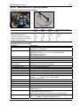
SES-2000
Narrow-Beam Parametric Sub-Bottom Profilers
User’s Guide
SES-2000 compact
SES-2000 light
SES-2000 standard
SES-2000 medium
SES-2000 deep
SES-2000 ROV
V 2.8 (June 2009)
2
SES 2000 User’s Guide
Information in this document is subject to change without notice and does not represent a commitment
on the part of INNOMAR Technologie GmbH. The software described in this document is furnished
under a license agreement or nondisclosure agreement. The software may be used only in
accordance with the terms of the agreement. It is against the law to copy the software on any medium
or transmit in any form except as specifically allowed in the license or nondisclosure agreement. No
part of this manual may be reproduced or transmitted in any form or by any means, electronic or
mechanical, including photocopying and recording, for any purpose without the express written
permission of INNOMAR.
© 1998-2009 INNOMAR Technologie GmbH. All Rights reserved.
Trademarks
INNOMAR is a registered trademark of Innomar Technologie GmbH.
Microsoft, MS-DOS, Windows and Windows 95/98/2000/NT are registered trademarks of Microsoft
Corporation.
Intel and Pentium are registered trademarks of Intel Corporation.
IBM and VGA are registered trademarks of IBM Corporation.
Software License Agreement
The copyright for the SES software is owned by Innomar Technologie GmbH ("INNOMAR "). The
software license agreement ("Agreement") sets forth the terms and conditions under which the
purchaser is licensed to use the SESWIN or ISE software ("Software"). This is a license agreement
and not an agreement for sale. INNOMAR continues to own the copy of the software and any other
copy that you are authorised to make pursuant to this agreement.
INNOMAR grants to you a non-exclusive license to use the software together with a SES-2000 system,
provided that you agree to the following:
Use of the Software
1. The license only applies to the purchaser of a parametric sub-bottom profiler SES-2000. The
purchaser is not allowed to pass the software to any other user without INNOMAR's written permission.
2. The purchaser may install one copy of the software on the computer integrated in the SES-2000
hardware and on another computer for post processing.
3. Neither the purchaser nor any other person are allowed to do the following:
•
give this software to any other person or institution
•
make any copies of this software, except for one backup copy, provided the backup copy is
not installed or used on any computer
•
modify, adapt, translate, reverse engineer, decompile, disassemble or otherwise attempt to
discover the source code of the software
•
transfer the software by telecommunication.
Copyright and Trademark Rights
The software is owned by INNOMAR. The software is licensed and distributed by INNOMAR for
surveying work (on-line and off-line) with the parametric sub-bottom profiler SES-2000. Its structure,
organization and code are the valuable trade secrets of INNOMAR. The software also is protected by
international treaty provisions. You may use trademarks only insofar as required to identify printed
output produced by the software, in accordance with accepted trademark practice, including
identification of trademark owner's name. Such use of any trademark does not give you any rights of
ownership in that trademark. Except as stated above, this Agreement does not grant you any
intellectual property rights in the software.
INNOMAR reserves the right to terminate this license if any terms of this Agreement are violated.
Innomar Technologie GmbH
SES-2000
Parametric Sub-bottom Profiler
User’s Guide
SES-2000 compact
SES-2000 light
SES-2000 standard
SES-2000 medium
SES-2000 deep
SES-2000 ROV
Innomar Technologie GmbH
V 2.8 (June 2009)
Innomar Technologie GmbH
Schutower Ringstr. 4
D-18069 Rostock
Germany
Telephone: +49(0)381/44079-0 Fax: +49(0)381/44079-299
[email protected]
http://www.innomar.com
Innomar Technologie GmbH
4
SES 2000 User’s Guide
Disclaimer
THE SOFTWARE AND HARDWARE IS BEING DELIVERED TO YOU AS IS AND INNOMAR
MAKES NO WARRANTY AS TO ITS USE OR PERFORMANCE. INNOMAR DOES NOT AND
CANNOT WARRANT THE PERFORMANCE OR RESULTS YOU MAY OBTAIN BY USING THE
SOFTWARE OR DOCUMENTATION. INOMAR AND ITS SUPPLIERS MAKE NO WARRANTIES,
EXPRESS OR IMPLIED, AS TO NONINFRINGEMENT OF THIRD PARTY RIGHTS,
MERCHANTABILITY, OR FITNESS FOR ANY PARTICULAR PURPOSE. IN NO EVENT WILL
INNOMAR OR ITS SUPPLIERS BE LIABLE TO YOU FOR ANY CONSEQUENTIAL, INCIDENTAL
OR SPECIAL DAMAGES, INCLUDING ANY LOST PROFITS OR LOST SAVINGS, EVEN IF AN
INNOMAR REPRESENTATIVE HAS BEEN ADVISED OF THE POSSIBILITY OF SUCH DAMAGES,
OR FOR ANY CLAIM BY ANY THIRD PARTY. SOME STATES OR JURISDICTIONS DO NOT
ALLOW THE EXCLUSION OR LIMITATION OF INCIDENTAL, CONSEQUENTIAL OR SPECIAL
DAMAGES, OR THE EXCLUSION OF IMPLIED WARRANTIES OR LIMITATIONS ON HOW LONG
AN IMPLIED WARRANTY MAY LAST, SO THE ABOVE LIMITATIONS MAY NOT APPLY TO YOU.
WHERE LIABILITY CANNOT BE LEGALLY EXCLUDED, BUT IT MAY BE LIMITED, INNOMAR'S
LIABILITY AND THAT OF IT`S SUPPLIERS SHALL BE LIMITED TO THE AMOUNT PAID FOR
THE SOFTWARE AND HARDWARE.
Remark
INNOMAR did its best to make software, hardware and manual free of faults. However, if there should
be a reason to complain or criticize, INNOMAR will always have an ear for your suggestions and hints
and will try to help.
INNOMAR reserves the right to change technical data.
© 1998-2009 Innomar Technologie GmbH. All rights reserved.
Innomar Technologie GmbH
SES 2000 User’s Guide
1
2
3
4
5
5
Important Hints – Attention Please!.................................................... 9
1.1
Safety Rules ............................................................................................................. 9
1.2
SES-2000 Manual..................................................................................................... 9
Getting Started ................................................................................. 11
2.1
SES-2000 System Overview and System Installation ............................................ 11
2.2
Installation and Basic Configuration of the SESWIN Software ............................... 14
2.3
Operating the SESWIN Software............................................................................ 15
2.4
Checklist for System Setup / Survey Start.............................................................. 19
SES-2000 Hardware / System Installation ....................................... 21
3.1
SES-2000 System Overview .................................................................................. 21
3.2
SES-2000 compact................................................................................................. 22
3.3
SES-2000 light........................................................................................................ 23
3.4
SES-2000 standard ................................................................................................ 24
3.5
SES-2000 medium.................................................................................................. 25
3.6
SES-2000 deep ...................................................................................................... 27
3.7
SES-2000 ROV....................................................................................................... 30
3.8
SES-2000 sidescan Extension ............................................................................... 32
3.9
SES-2000 xxx AR (Advanced Receiver Array) ....................................................... 33
3.10
Transducer Handling and Installation ..................................................................... 34
3.11
Main Unit Installation .............................................................................................. 38
3.12
SES-2000 Front Panel: Connectors and Switches ................................................. 39
3.13
SES-2000 Rear Panel ............................................................................................ 43
3.14
Installing additional Sensors ................................................................................... 44
3.15
SES-2000 power supply requirements ................................................................... 45
Installing the SESWIN System Software.......................................... 47
4.1
Installing SESWIN software.................................................................................... 47
4.2
Initial Setup using the SES Configuration Tool....................................................... 47
SES for Windows (SESWIN System Software)................................ 51
5.1
The SESWIN screen............................................................................................... 51
5.2
SESWIN Main Menu............................................................................................... 52
5.3
SESWIN Button Bar / Hot Keys .............................................................................. 53
5.4
SESWIN Level Display ........................................................................................... 56
5.5
SESWIN Depth Display .......................................................................................... 56
5.6
Monitoring Windows ............................................................................................... 56
5.7
Status Bar ............................................................................................................... 57
5.8
Parameter Menu / Control Parameters................................................................... 58
5.9
Quick Controls ........................................................................................................ 65
5.10
SESWIN System Settings....................................................................................... 66
5.11
SESWIN System Interfaces.................................................................................... 77
5.12
Network Settings..................................................................................................... 87
5.13
SIS Monitor, MCP Monitor ...................................................................................... 92
Innomar Technologie GmbH
6
6
7
8
9
SES 2000 User’s Guide
5.14
File Tools.................................................................................................................93
5.15
Other Tools / Info Screens ......................................................................................95
5.16
The Printed Echo Plot .............................................................................................96
5.17
Data File Formats ....................................................................................................97
SES-2000 Synchronisation (Trigger modes) ....................................99
6.1
Internal Synchronisation........................................................................................100
6.2
External Synchronisation.......................................................................................100
6.3
Alternating Trigger.................................................................................................105
6.4
Deep Sea Pulse Mode / Deep Sea Burst Mode ....................................................107
How to …? ......................................................................................109
7.1
How to avoid the engine’s noise by proper transducer mounting..........................109
7.2
How to install the SES-2000 ROV transducer .......................................................111
7.3
How to install and set up a motion sensor.............................................................113
7.4
How to setup the SES-2000 compact USB device driver......................................115
7.5
How to update the SESWIN software....................................................................119
7.6
How to boot and shutdown the SES-2000 systems ..............................................121
7.7
How to record echo data .......................................................................................122
7.8
How to display previously recorded data...............................................................123
7.9
How to print out an echogram ...............................................................................124
7.10
How to set marker lines in the echoprint ...............................................................126
7.11
How to set up Navigation Data Interface (SIS)......................................................131
7.12
How to set up UTM conversion .............................................................................132
7.13
How to avoid interference with other acoustic systems.........................................139
7.14
Using the Broadcast Server to display data on HYPACK......................................148
7.15
Using SES NetView to display echo data on remote computer.............................151
7.16
How to remote-control a SES-2000 SBP ..............................................................153
7.17
How to transfer SES-2000 SBP data to another computer ...................................159
7.18
How to use SESWIN’s documentation and report tools ........................................162
Maintenance and Error Handling ....................................................165
8.1
Hardware Handling and Maintenance ...................................................................166
8.2
Special SES-2000 compact problems ...................................................................169
8.3
SESWIN error messages ......................................................................................170
8.4
No incoming data ..................................................................................................172
8.5
SESWIN functions seem not to work ....................................................................173
8.6
Signal detection problems .....................................................................................175
8.7
Printer Problems....................................................................................................177
8.8
Motion Sensor Problems .......................................................................................178
Technical Background ....................................................................179
9.1
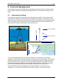
Sub-bottom Profiling..............................................................................................179
9.2
Important Properties of Sub-bottom Profilers ........................................................180
9.3
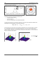
Transducer Characteristics ...................................................................................183
Innomar Technologie GmbH
SES 2000 User’s Guide
7
9.4
Nonlinear (Parametric) Sub-bottom Profilers........................................................ 186
9.5
SES-2000 Parametric Sub-bottom Profilers ......................................................... 190
9.6
Signal Processing ................................................................................................. 192
9.7
Acoustics of gassy sediments............................................................................... 195
Appendix
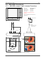
A1 SES-2000 Transducers................................................................. 201
A.1.1 SES-2000 compact / light / standard Transducer ................................................. 201
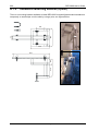
A.1.2 Transducer Mounting Bracket (Option)................................................................. 202
A.1.3 SES-2000 medium Transducer ........................................................................... 203
A.1.4 SES-2000 deep Transducer ................................................................................. 205
A.1.4 SES-2000 ROV Transducer ................................................................................. 206
A.2 SES-2000 Specifications .............................................................. 207
A.2.1 SES-2000 compact Specifications........................................................................ 207
A.2.2 SES-2000 light Specifications............................................................................... 209
A.2.3 SES-2000 standard Specifications ....................................................................... 211
A.2.4 SES-2000 medium Specifications ........................................................................ 213
A.2.5 SES-2000 deep Specifications ............................................................................. 215
A.2.7 SES-2000 ROV Specifications ............................................................................. 219
A.3 SES-2000 Options ....................................................................... 223
A.4 ISE Post-Processing Software...................................................... 227
A.5 Supported Motion Sensors and Printers ....................................... 229
A.6 Motion Sensor Housing................................................................. 231
A.7 GPS NMEA Sentences ................................................................. 233
A.8 Motion Sensor Data Formats ........................................................ 237
A.9 TCP/IP Error Codes ...................................................................... 243
Innomar Technologie GmbH
8
SES 2000 User’s Guide
Blank Page
Innomar Technologie GmbH
SES 2000 User’s Guide
9
1 Important Hints – Attention Please!
1.1
Safety Rules
For the user's safety and the safety of any person nearby the SES-2000 systems and for the
non-damageable operation of the system it is strictly pointed out that:
THE SES-2000 DEVICE MUST ONLY BE OPENED BY AUTHORIZED STAFF
CABLES MUST ONLY BE CONNECTED OR DISCONNECTED WHEN THE
HARDWARE IS SWITCHED OFF; ESPECIALLY THE TRANSDUCER CABLE
THE EQUIPMENT MUST ONLY BE USED IN SYSTEM MODE; IF THE
TRANSDUCER IS CONNECTED TO THE SES-2000 DEVICE AND IS SITUATED
IN WATER
IT IS FORBIDDEN TO SWIM OR DIVE WHILE THE SES-2000 SYSTEM IS
WORKING
THE SES-2000 SYSTEM IS NOT WATERPROOF AND HAS TO BE USED IN
DRY AND WATER PROTECTED ROOMS
ALLOW FREE ACCESS OF AIR TO THE COOLING SLITS TO AVOID
OVERHEATING
THE SES-2000 DEVICE IS HEAVY BUT ALSO A SENSITIVE INSTRUMENT AND
SHOULD BE CARRIED VERY CAREFULLY
THE TRANSDUCER’S ACTIVE AREA HAS TO BE PROTECTED AGAINST
MECHANICAL DAMAGES AND PRESSURE
DO NOT CHANGE THE SETUP OF THE SYSTEM's OPERATING SYSTEM OR
CONTROL-PC’s BIOS
DO NOT INSTALL ANY OTHER SOFTWARE OR DEVICE DRIVER ON THE SES
CONTROL COMPUTER
INNOMAR is not liable for any damages that result from disregard these safety rules or any
other improper operation of the SES-2000 systems.
1.2
SES-2000 Manual
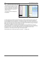
This manual describes how to install and use the SES-2000 sub-bottom profilers. It is divided
into a hardware orientated part and a description of the SES-2000 control and data
acquisition software “SES for Windows” (SESWIN).
Some facts about the document structure:
•
Italics is used for file and path names.
•
Keys belonging to the keyboard are enclosed in brackets. If some keys have to be
pressed at the same time, they are separated by ‘+’
(example: Press [Ctrl]+[Alt]+[Del] to restart your computer).
•
The symbol
marks a very useful hint or key fact.
Innomar Technologie GmbH
10
SES 2000 User’s Guide
Blank Page
Innomar Technologie GmbH
SES 2000 User’s Guide
11
2 Getting Started
In this chapter a short introduction to the installation and operation of the SES-2000 subbottom profiler is given. It is intended as short reference for both, new and experienced SES
operators. References to the detailed descriptions in the other chapters are provided.
In the last section of this chapter on page 19 a checklist is provided that should be used
during system installation and setup to make sure that all settings that are necessary to get
good survey results are made.
2.1
SES-2000 System Overview and System Installation
For a wide range of applications and water depths there are different SES-2000 systems
available. This section gives a short overview. The SES-2000 system components and the
installation are described in detail in chapter 3 on page 21.
The SES-2000 systems consists of the following components:
•
•
•
•
Main system unit with the transmitters, receivers, amplifiers
(there is an extension unit for the SES-2000 medium and deep systems)
External PC (notebook) for the SES-2000 compact system
Transducer array used to transmit and receive the signals
Workstation (optional) to remote-control the system via network (LAN).
Within the cabinet of the main unit there are the power supply, transmitter units, units for
analogue and digital signal processing and an industrial personal computer. The SES-2000
compact is shipped without an integrated PC, but optionally with a notebook PC. The
operating system of the control-PC is MS Windows XP.
SES-2000 compact
•
main unit
•
external PC
•
transducer
SES-2000 light
•
main unit
•
transducer
SES-2000 standard
•
main unit
•
transducer
Innomar Technologie GmbH
12
SES 2000 User’s Guide
SES-2000 medium
•
main unit
•
extension unit
•
transducer
SES-2000 deep
extension unit
main unit
power supply
transducer
SES-2000 ROV
•
main unit
•
transducer
2.1.1 SES-2000 Transducer Installation
Very important is the proper installation of the transducer to avoid noise coming from the ship
or flow-noise at the transducer’s surface, see section 3.10 on page 34 for details.
Make sure the transducer is fixed firmly to the ship using a stable mounting bracket and/or
pipe. The transducer has to be below water level and must not vibrate while travelling. Try to
avoid any noise going to the transducer.
The system must not be switched on if the transducer is not installed properly and placed
below water level.
For most systems the transducer cable is moulded non-removable to the transducer and
cannot be removed. Only for the SES-2000 ROV system there is a plug-socket connection at
the transducer.
Innomar Technologie GmbH
SES 2000 User’s Guide
13
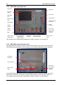
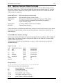
2.1.2 SES-2000 Main Unit / Connectors
Detailed descriptions of the front panels of the different SES-2000 systems are given in
sections 3.2 to 3.7. The connectors and switches are described in section 3.12 on page 39.
SES-2000 compact
power control
LEDs
Fuse
Trigger In/Out
main power switch
Analog Out
power connector
Motion sensor
input
Transducer
connector
USB control port
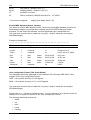
SES-2000 standard / medium / deep
Floppy Disk
USB ports
10.4” TFTDisplay
PC network
Navigation
Input
Video Output
Motion sensor
Input
Keybord / Mouse
connectors
Depth Output
Printer
connector
System
Hotkeys
Display
Control
Fuse, main
power switch
and power
connector
GND
Analog In/Out
Trigger In/Out
Link to extension
unit (SES-2000
medium / deep)
Transducer
connector
Power connector
(SES-2000 deep)
Innomar Technologie GmbH
Power control
LEDs
14
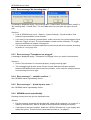
2.2
SES 2000 User’s Guide
Installation and Basic Configuration of the SESWIN Software
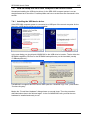
2.2.1 Installing the SESWIN Software
There is system software, called SES for Windows (or SESWIN for short) that is delivered
together with the SES-2000 system to manage the system’s on-line operation, data acquisition as well as data replay. This software is preinstalled on the built-in control PC of the SES2000 system. To ensure proper operation of the system, do not change the settings of the
BIOS and the Windows OS and do not install any other software packages and device
drivers.
If necessary, the SESWIN software can be reinstalled as described in section 4.1 on page 47.
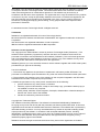
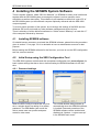
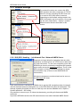
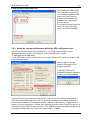
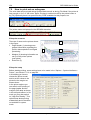
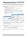
2.2.2 Initial Setup using the SES Configuration Tool
SES-2000 systems are delivered with a separate configuration tool (sesconfig.exe) for basic
system settings that has to be run before starting the SESWIN software for the first time.
The necessary settings are explained in section 4.2 on page 47.
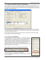
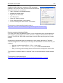
2.2.3 Starting the SESWIN Software
Usually you find a link on the desktop to start the SESWIN application.
SES for Windows.lnk
The software is briefly described in the next section, a detailed description is
given in chapter 4.2.4 on page 50.
Innomar Technologie GmbH
SES 2000 User’s Guide
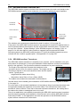
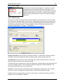
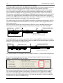
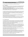
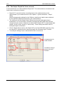
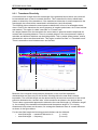
2.3
15
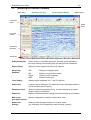
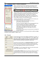
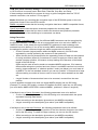
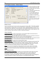
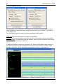
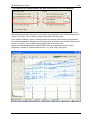
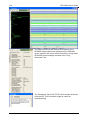
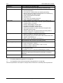
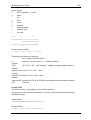
Operating the SESWIN Software
Main Menu
Button Bar / Hot Keys
Signal Amplitude Display
Depth Display
Parameter
Menu
Depth
Ruler
Echo Plot
Screen
Monitoring
Windows
Status Bar
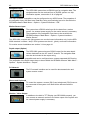
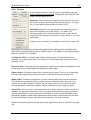
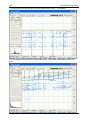
Echo plot display
Online output of calculated echogram. Scrolling speed depends on
the range settings, the resulting ping rate and process parameters.
Depth display
Display of water depth measured by HF channel
Monitoring
Windows
SIS:
Display of navigation data
MS:
Display of motion sensor data
Signal:
Display of echo envelope
MAP:
Display of track plot
Level display
Displays signal amplitude of LF- and HF-channel
Depth ruler
A depth scale is displayed. The depth values are calculated based on
a given constant sound velocity.
Parameter menu
Setting of hardware parameters (e.g. choosing frequency and pulse
length, setting the amplifiers)
Status bar
Display of essential system settings and status display for the system
Main menu
(pull down menus)
System configuration, interface configuration, help.
Button bar /
Hotkeys
Setting of most important features for system mode
(e.g. switching on/off transmitting, data recording, printing)
Innomar Technologie GmbH
16
SES 2000 User’s Guide
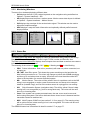
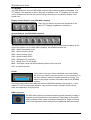
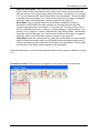
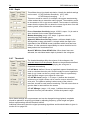
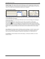
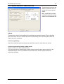
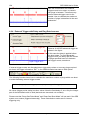
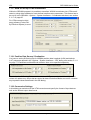
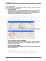
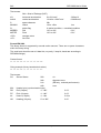
2.3.1 SESWIN Button Bar / Hot Keys
File Mode - F2
Exit Program - Alt+F4
System Mode - F2
Marker - F12
Open File - F3
Next Profile - F11
Transmitter- F4
Echoprint Mode- F10
Record - F5
Split View - F9
Printer - F6
HF Channel - F7
Quick Controls
LF Channel - F7
File Mode
For replay only
System Mode
For data acquisition
Open File
To load files for replay only (disabled during system mode)
Transmitter
Start/Stop sound ping (should always be active for data acquisition)
Record
Start/Stop recording data
Printer
Start/Stop online printing
Quick Controls
Switch on/off reduced Parameter Menu (“Quick Controls”)
LF Channel
Display echoprint of low frequency (LF) data *
HF Channel
Display echoprint of high frequency (HF) data *
Split View
Display echoprints of both low and high frequency data simultaneously **
Echoprint Mode
There are two modes for echoprints: “Amplitude” and “High Resolution” ***
Next Profile
Increase profile counter by 1 and restart data logging, if active
Marker
Manual event marker (with annotated number).
Exit Program
Press to exit program. ***
*
Both channels are recorded regardless of this selection. These options only concern
which channels are displayed and printed.
**
If the split view button is pressed, one channel is displayed in the left side of the Echo
Screen Plot, and one channel in the right side. Whichever button out of the LF Channel
or HF Channel is also pressed, will determine which channel is displayed to the right
side. The channel displayed to the right side is the one that will be printed.
***
These signal processing options are explained in section 9.6.2 on page 193.
**** To exit the program, the correct sequence should be:
Stop printer (F6), Stop Record (F5), Stop transmitter (F4), Exit Program (ALT F4)
A more detailed description of the SESWIN button bar is given in section 5.3 on page 53.
Innomar Technologie GmbH
SES 2000 User’s Guide
17
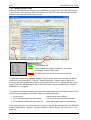
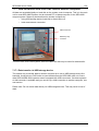
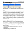
2.3.2 Monitoring Windows
There are four windows displaying different data:
•
SIS displays the first 6 (of 8) values imported on the navigation string as defined on
Options – System Interfaces – SIS.
•
MS displays data received from a motion sensor. Motion sensor data import is defined
on Options – System Interfaces – Motion Sensor.
•
SIG displays the envelope of the received echo signal. This window can be used to
adjust the amplifier settings.
•
MAP displays a map with track information and optionally defined profile lines and
target positions
The SESWIN monitoring windows are described in detail in section 5.6 on page 56.
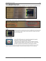
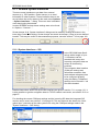
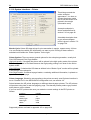
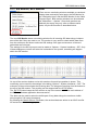
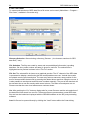
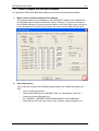
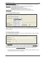
2.3.3 Status Bar
The upper part of the Status Bar displays a variety of parameters being used for the survey:
Range, LF Channel Frequency and Pulse Length, Profile number and Data file size.
The lower part of the Status Bar displays local computer time and date as well as some status
information about attached devices.
The meaning of the colours is Green = OK, Yellow = Warning and Red = Not Working.
•
PRN: Printer Information. Red colour (as above) will mean no printer connected, out
of paper etc.
•
HD / NET: Hard Disc space. This shows the space remaining on the hard disc the
data is being recorded on to. The colour will change to yellow with 250MB remaining,
and then go to red when close to empty. HD refers to the local hard disc while NET
refers to the hard disc of a remote-controlled system.
•
MS: Motion Sensor. The colour will be yellow if there is a problem such as the MS
string is not recognised or maybe vessel movements are too abrupt to be compensated for (Instable Flag!), and red if the motion sensor is unplugged or not working.
•
SIS: Ship Information System (navigation data). The will be yellow if there is data
coming but is not recognised (e.g. due to wrong baud rate). The colour will be red if
there is no incoming data.
•
Case: If the system has a water-protected case, the rear cover must be removed
before using the system. Red colour indicates that a closed cover is detected and the
transmitter cannot be switched on!
•
MCP: Multi Purpose COM Port (see section 5.11.3 on page 81). The warning colour
will be yellow if there is data coming in but is not recognised. The colour will be red if
there is no incoming data.
The SESWIN status bar is described in detail in section 5.7 on page 57.
Innomar Technologie GmbH
18
SES 2000 User’s Guide
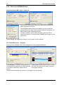
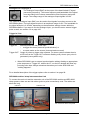
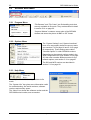
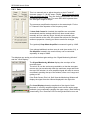
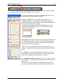
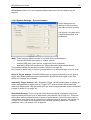
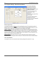
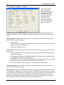
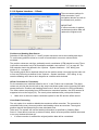
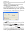
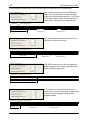
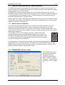
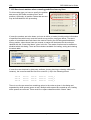
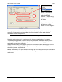
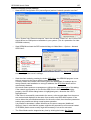
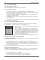
2.3.4 Some more SESWIN Dialogs
Network settings (Main menu – Options)
The network functions can connect the SES-2000 systems with
other computers via TCP/IP.
The SESWIN software has to be installed not only on the SES
system (Server) but also on the remote computer (Client) and you
have to set the port addresses properly.
It is also possible to receive SIS (navigation) data via TCP/IP
network connection. For this purpose a NMEA server has to be set
up properly.
These settings are explained in section 5.12 on page 87 of this manual.
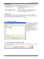
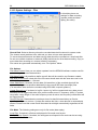
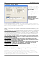
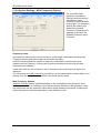
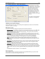
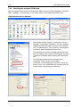
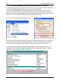
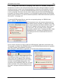
File Tools (Main menu – Program)
Some tools are available for the file management of the recorded SES data:
A File Browser is used for easier selection of A File Cutter is used for the creation of data
recorded data to replay with the SES software. files with sub-selections of areas of interest
It provides an alternative method for file
from bigger data sets.
access.
These tools are described in section 5.14 on page 93 of this manual.
Innomar Technologie GmbH
SES 2000 User’s Guide
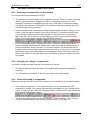
2.4
19
Checklist for System Setup / Survey Start
This checklist will assist you during system installation and preparing a survey. It is not a
replacement for reading the regarding chapters in this manual.
2.4.1 Transducer Installation
Transducer is mounted in stiff frame or supporting structure.
Transducer is decoupled from the ship’s hull by rubber.
Transducer’s active area is horizontally.
Transducer is located as far away from noise sources as possible.
Transducer is covered by water all times, even at rough sea conditions.
An additional ground wire is going from the transducer’s housing to the main unit.
The draught of the transducer (distance from water surface to bottom of transducer) is
measured and noted.
2.4.2 Electronic Unit Installation
Electronic unit(s) is placed in a dry environment.
Cooling slits in the front and rear panel are free and there is enough space for airflow.
Main power supply is checked (range 110-240 V AC / 50-60 Hz). If a small generator is
used, a ground wire should be connected to the generator going to the SES main unit.
Power cable(s) plugged in.
Transducer cable(s) plugged in.
Additional ground wire from the transducer connected to the main unit.
If there are more than one electronic unit, all units are connected by ground wires.
Additional sensors (Motion sensor / GPS) are connected to the specified serial ports.
(Since sometimes the Windows OS is confused if the sensors are connected while
booting, this step can be postponed)
Check if all connectors are fastened properly and all cables are fixed.
For the SES-2000 ROV pressure vessel a pressure test has to be made.
2.4.3 System power-up
Make sure the transducer is below water level and covered by water all times.
Switch on main power → power switch and all power LEDs are flashing.
Windows OS is booting and the Windows desktop shows up.
Now it’s safe to connect additional sensors, if postponed (see above).
Invoke the SESWIN software. If there are any error messages, refer to section 8.2 on
page 169.
The echoprint part of the SESWIN window starts scrolling from right to left. If not, check
if “System Mode” is switched on [F2] and the synchronisation mode is set to “Internal”
(SESWIN main menu Options – System Settings – System).
2.4.4 SESWIN settings
Set transducer’s draught in SESWIN main menu Options – System Settings – System.
Check incoming SIS (navigation) data
Check incoming motion sensor data
Check all other settings in the Options – System Settings and System Interfaces dialogs
that may be important for your survey.
Innomar Technologie GmbH
20
SES 2000 User’s Guide
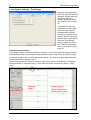
2.4.5 System check / preparing survey start
Make sure the transducer is below water level and covered by water all times.
Switch on the transmitter [F4].
Switch to “split view” to display both data channels (HF and NF) [F9].
Set the range appropriate to find the seafloor.
Optimize the gain settings for both channels.
Optimize the range settings.
Optimize frequency, pulse length and gain settings.
Check and optimize the signal processing settings.
Check the settings for annotation, profile number and marker counter.
Start data recording [F5].
Check printer if necessary [F6].
After some minutes switch off data recording [F5] and transmitter [F4] (and printer [F6]).
Switch to “File Mode” [F2]
Open the new-recorded data file [F3] and check if the data was recorded properly.
Switch back to “System Mode” [F2].
Innomar Technologie GmbH
SES 2000 User’s Guide
21
3 SES-2000 Hardware / System Installation
3.1
SES-2000 System Overview
The SES-2000 systems consists of the following components:
•
Main system unit containing the transmitters, receivers, amplifiers
(there is an extension unit for the SES-2000 medium and deep systems)
•
External PC (notebook) for the SES-2000 compact system
•
Transducer used to transmit and receive the signals
•
Workstation (optional) to remote-control the system via network (LAN).
Within the cabinet of the main unit there are the power supply, transmitter units, units for
analogue and digital signal processing and an industrial personal computer. The SES-2000
compact is shipped without any integrated PC. The operating system of the control-PC is MS
Windows XP.
Mouse and keyboard have to be connected to the device. On-line printouts can be made
using a wide range of printers, see appendix A.5 on page 229 for supported printers. While
being in system mode other printers cannot be used due to the real time requirements.
Incoming data is stored on hard disk. The standard backup medium is an external USB-2
hard disk, but backups are also possible via network connection. Data should not be stored
directly to external storage devices during data acquisition because of real-time requirements.
The SES-2000 systems have serial interfaces for navigation data (RS232, Nav-Input) and for
the connection of a motion sensor (RS232, Motion-Sensor-Input). A serial ASCII output for
the depth values is also available.
Besides that there are:
•
Trigger-Input for external triggering SES-2000 in slave mode
•
Trigger-Output for triggering other echo sounders (SES-2000 in master mode)
Other interfaces are optional or can be realised on customers’ request.
Technical specifications for the SES-2000 systems are given in appendix A.2 on page 207.
Innomar Technologie GmbH
22
3.2
SES 2000 User’s Guide
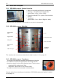
SES-2000 compact
3.2.1 SES-2000 compact System Overview
•
Main unit containing all electronic components
•
Housing: ½ 19” cabinet with 7 height units
(about 30cm × 35cm × 40cm / 23kg)
•
External notebook PC for system control and data
storage
•
Transducer
(about 30cm × 7cm × 26cm / 25kg incl. cable)
Technical specs and a sketch of the transducer are given in the appendix.
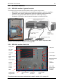
3.2.2 SES-2000 compact Main Unit
power control
LEDs
Fuse
Trigger In/Out
main power switch
Analog Out
power connector
Motion sensor
input
Transducer
connector
USB control port
The switches and connectors are described in detail in section 3.12 on page 39.
3.2.3 SES-2000 compact Transducer
The length of the cable that connects the transducer to the main
unit is 20m for compact and light systems The weight and the
dimensions depend on the used transducer frame. Typical values:
-
weight with 20m cable: about 25kg
-
dimensions: about 30cm x 7cm x 26cm (WHD)
The cable is moulded non-removable to the transducer.
General advice for the handling and installation of SES-2000 transducers is given in section
3.9 on page 33.
Innomar Technologie GmbH
SES 2000 User’s Guide
3.3
23
SES-2000 light
3.3.1 SES-2000 light System Overview
•
Main unit containing all electronic components and
control PC
•
Housing: 19” cabinet with 8 units
(about 52cm × 36cm × 40cm / 38kg)
•
Transducer
(about 30cm × 7cm × 26cm / 25kg incl. cable)
Technical specs and a sketch of the transducer are given in appendix.
3.3.2 SES-2000 light Main Unit
Depth Output
10.4” TFTDisplay
USB ports
Navigation
Input
Keybord / Mouse
connectors
Motion sensor
Input
Video Output
PC Network
System
Hotkeys
Display
Control
Printer
connector
Analog In/Out
Trigger In/Out
GND
Transducer
connector
Power control
LEDs
Fuse, main power switch
and power connector
The switches and connectors are described in detail in section 3.12 on page 39.
3.3.3 SES-2000 light Transducer
The length of the cable that connects the transducer to the main
unit is 20m for compact and light systems The weight and the
dimensions depend on the used transducer frame. Typical values:
-
weight with 20m cable: about 25kg
-
dimensions: about 30cm x 7cm x 26cm (WHD)
The cable is moulded non-removable to the transducer.
General advice for the handling and installation of SES-2000 transducers is given in section
3.9 on page 33.
Innomar Technologie GmbH
24
3.4
SES 2000 User’s Guide
SES-2000 standard
3.4.1 SES-2000 standard System Overview
•
Main unit containing all electronic components
and control PC
•
Housing: 19” cabinet with 9 height units
(about 52cm × 44cm × 40cm / 49kg)
•
Transducer
(about 30cm × 7cm × 26cm / 30kg incl. cable)
Technical specs and a sketch of the transducer are given in the appendix.
3.4.2 SES-2000 standard Main Unit
Floppy Disk
USB ports
10.4” TFTDisplay
PC network
Navigation
Input
Video Output
Motion sensor
Input
Keybord / Mouse
connectors
Depth Output
Printer
connector
System
Hotkeys
Display
Control
GND
Fuse, main
power switch
and power
connector
Analog In/Out
Transducer
connector
Trigger In/Out
Power control
LEDs
The switches and connectors are described in detail in section 3.12 on page 39.
Optionally the SES-2000 standard system can be prepared for easy upgrading to SES-2000
medium, see appendix A.3 page 223 for details. The front panel is than like shown on page
25.
3.4.3 SES-2000 standard Transducer
The length of the cable that connects the transducer to the main
unit is 30m. The weight and the dimensions depend on the used
transducer frame. Typical values:
-
weight with 30m cable: about 30kg
-
dimensions: about 30cm x 7cm x 26cm (WHD)
The cable is moulded non-removable to the transducer.
General advice for the handling and installation of SES-2000 transducers is given in section
3.9 on page 33.
Innomar Technologie GmbH
SES 2000 User’s Guide
3.5
25
SES-2000 medium
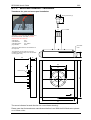
3.5.1 SES-2000 medium System Overview
The following figure shows the SES-2000 medium system components:
•
•
•
•
Main system unit and extension unit containing transmitters, receivers, amplifiers
Transducer array used to transmit and receive the signals (cable length 30m)
Receiver array (optional SES-2000 medium AR, cable length 30m)
Workstation (optional) to remote-control the system via network (LAN).
The technical specs including dimensions and weight of the system components and
sketches of the transducer are given in the appendix.
3.5.2 SES-2000 medium Main Unit
Floppy Disk
USB ports
10.4” TFTDisplay
PC network
Navigation
Input
Video Output
Motion sensor
Input
Keybord / Mouse
connectors
Depth Output
Printer
connector
System
Hotkeys
Display
Control
Fuse, main
power switch
and power
connector
GND
Analog In/Out
Trigger In/Out
Link to extension
unit
Transducer
connector
Power control
LEDs
The switches and connectors are described in detail in section 3.12 on page 39.
Innomar Technologie GmbH
26
SES 2000 User’s Guide
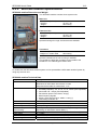
3.5.3 SES-2000 medium Extension Unit
The SES-2000 medium system consists of two electronic blocks, the main unit (similar to the
SES-2000 standard system) and an extension unit containing additional power amplifiers.
Transducer
connectors
Link to main unit
Fuse, main
power switch
and power
connector
power control
LEDs
The switches and connectors are described in detail in section 3.12 on page 39.
If the power of the SES-2000 medium system is not required (for instance in shallow water) it
can be operated without the extension unit like a SES-2000 standard system. This has to be
set up in the “Options – System Settings” of the SESWIN program, see section 5.10.1 on
page 66. On the other hand it is also possible to upgrade special prepared SES-2000
standard systems into SES-2000 medium systems. For this the standard system has to be
ordered with the “medium upgrade option”, see appendix A.3 on page 223.
3.5.4 SES-2000 medium Transducer
The SES-2000 medium transducer is available in two versions, one for installation on a pole
and another for permanent or moon-pool installation. Both transducer versions are described
briefly in the appendix. The figure below shows the transducer for pole installations.
The length of the cable that connects the transducer to the
electronic device is 30m for medium systems. The weight and the
dimensions depend on the used transducer frame and the system
variant. Typical values:
-
weight with 30m cable: about 80 kg
-
dimensions: about 50cm x 12cm x 50cm (WHD)
The cables are moulded non-removable to the transducer.
General advice for the handling and installation of SES-2000 transducers is given in section
3.9 on page 33.
For moon-pool or hull-mounted installations it is important to keep in mind that there has to be
enough space behind the transducer to bend the cables. The minimal bend radius of the
transducer cable is 200mm. There has to be water behind the transducer, the sealing has to
be made at the cables or standpipes have to be used!
There is an application note available summarizing the SES-2000 medium system’s specials
and discussing a possible rack-installation of the electronic units: AN-22 “SES-2000 medium
Sub-bottom Profiler”. In this application note also the operation of the SES-2000 medium
system without extension unit is discussed.
Innomar Technologie GmbH
SES 2000 User’s Guide
3.6
27
SES-2000 deep
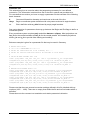
3.6.1 SES-2000 deep System Overview
The following figure shows the SES-2000 deep system components:
•
•
•
•
Main system unit and extension unit containing transmitters, receivers, amplifiers
Power supply unit
Transducer array used to transmit and receive the signals (cable length 30m)
Workstation (optional) to remote-control the system via network (LAN).
Remote-control also possible via KVM extension, see section 7.14 on page 148.
The electronics is separated into
three units for easy handling and
transportation. These units have
to be placed close together; the
cables used for interconnection
have a length of about 2 meters.
For permanent installation it is
also possible to mount the three
components into one 19-inch
rack.
The transducer is split into 3
sections for easy handling, too.
It has to be installed into a
moon-pool or fitted to the ship’s
hull using a streamlined
housing.
transducer
power and link cables
extension unit
main unit
power supply
The technical specs including dimensions and weight of the system components and
sketches of the transducer are given in the appendix.
Innomar Technologie GmbH
28
SES 2000 User’s Guide
3.6.2 SES-2000 deep Main Unit
Floppy Disk
USB ports
10.4” TFTDisplay
PC network
Navigation
Input
Video Output
Motion sensor
Input
Keybord / Mouse
connectors
Depth Output
Printer
connector
System
Hotkeys
Display
Control
Fuse, main
power switch
and power
connector
GND
Analog In/Out
Trigger In/Out
Link to extension
unit (SES-2000
medium / deep)
Transducer
connector
Power connector
(SES-2000 deep)
Power control
LEDs
The switches and connectors are described in detail in section 3.12 on page 39.
3.6.3 SES-2000 deep Extension Unit
The SES-2000 deep system consists of two electronic blocks, the main unit (similar to the
SES-2000 standard system) and an extension unit containing additional power amplifiers.
Transducer
connectors
Link to main unit
Fuse, main
power switch
and power
connector
power control
LEDs
For the SES-2000 deep system there is an additional power connector (placed right of the
transducer connectors; not shown in the figure above) going to the separate power unit.
The switches and connectors are described in detail in section 3.12 on page 39.
Innomar Technologie GmbH
SES 2000 User’s Guide
29
3.6.4 SES-2000 deep Power Supply Unit
For the SES-2000 deep system there is an additional power unit that has to be connected to
both, the main unit and the extension unit.
Power supply for
extension unit
Power supply for
main unit
Power OUT
connectors
Power IN (mains)
connectors
The switches and connectors are described in detail in section 3.12 on page 39.
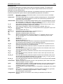
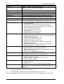
3.6.5 SES-2000 deep Transducer
The SES-2000 deep system is fitted with a
transducer for both, HF (35kHz) and LF (2–7kHz)
operation. For easy handling the transducer array is
divided into three sections, see figure. The cables
are moulded non-removable to the transducer.
A technical sketch of the transducer is provided in
the appendix.
Weight and dimensions of 1 section is as follows:
Dimensions (L×W×H)
Weight in air
Weight of cable (30m)
77 cm × 24 cm × 18 cm
about 60 kg
about 15 kg
The transducer of the SES-2000 deep system has to be installed in a moon-pool or at the
ship’s hull, see figures below. There has to be enough space behind the transducer to bend
the cables. The minimal bend radius of the transducer cable is 200mm. There has to be water
behind the transducer, the sealing has to be made at the cables or standpipes have to be
used!
SES-2000 deep transducer prepared for moon-pool
installation
SES-2000 deep transducer mounted permanently in a
streamlined dome below a ship’s keel
General advice for the handling and installation of SES-2000 transducers is given in section
3.9 on page 33.
Innomar Technologie GmbH
30
3.7
SES 2000 User’s Guide
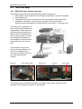
SES-2000 ROV
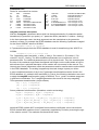
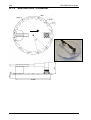
3.7.1 SES-2000 ROV System Overview
The SES-2000 ROV system is a pressure-proof version of the SES-2000 standard subbottom profiler intended for installation on remotely operated vehicles (ROV). There are
systems for different depth ratings available. The dimensions and weights of the system
components vary with the depth rating. The system is operated remote-controlled using a
ship-based computer that is connected to the system via network (TCP/IP).
For the SES-2000 ROV system there is an additional service manual available.
The following figure shows the main system components (pressure vessel and pressure-proof
transducer) mounted on a HIROV for operation.
Pressure vessel
Transducer
Mounted on a HIROV
Please note that you have to wait for at least 6 minutes after shut-down before re-powering
the pressure vessel in case you need to restart the system. There is an online USV inside
and otherwise the internal PC would not boot properly.
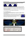
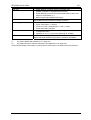
3.7.2 SES-2000 ROV Main Unit (Pressure Vessel)
Power and serial
interface connector
Transducer
connector
(External Trigger,
Motion Sensor)
Pressure relief valve
Data Connector
TCP/IP and
leakage
triangular plate pointing
downwards to indicate
the mounting position
Pressure sensor
and GND contact
Service connector
The connectors are described in detail in appendix A.2.6 on page 219.
Innomar Technologie GmbH
SES 2000 User’s Guide
31
Important notes for the installation of the pressure vessel
•
A triangular plate (pointing downwards) indicates the mounting position of the pressure
vessel on the ROV.
•
Don’t use the plastic handles on the pressure vessel’s end cap for transportation and
handling, please use the special handling tool shipped with the vessel.
•
All connectors have to be protected by pressure caps or dust caps when the pressure
vessel is shipped, mounted or not in use.
•
Before diving, make sure all plugs are connected tightly and all unused connectors
are protected by dummy plugs (pressure caps turned out not to be sufficient).
•
The cable’s connectors have to be protected by dust caps if not used.
•
Never plug and unplug connectors when power is switched on.
•
A separate ground wire must be connected between the GND contact on the transducer
and the GND contact on the pressure vessel.
•
An additional ground connection should be established between the pressure vessel
and the ROV itself.
•
The sealing test of the pressure vessel should be done with low pressure, but not less
than 0.7 bars.
•
During transportation the shipped transport box has to be used.
3.7.3 SES-2000 ROV Transducer
•
For the SES-2000 ROV system a pressure proof transducer
is used.
•
weight: about 25 kg
•
dimensions: about ∅ 50cm × 5cm
•
There is a plug-socket connection for the cable.
During transport and installation the transducer’s active area should be protected against
mechanical damages.
The transducer has to be mounted horizontally and there must be no turbulences below the
transducer, caused by gaps, noses or propellers in front of the transducer’s mounting place.
The transducer must not be placed onto vibrating constructions and should be acoustically
decoupled from the ROV’s mounting frame using elastic material (e.g. rubber).
During operation the transducer has to be covered by water all the time. To secure this, the
transmitters are deactivated if the pressure sensor in the electronic container detects a tow
depth less than 5 meters.
Important notes for the installation of the transducer
•
An arrow on top of the transducer marks the forward direction.
•
The cable has to be laced onto the cable holder on top of the transducer.
•
The transducer cable must not be plugged/unplugged when power is switched on.
•
If the transducer cable is not plugged in, the connector has to be protected by a
pressure cap.
•
A ground wire has to be connected between the GND contact on the transducer and the
GND contact on the pressure vessel.
•
During transportation the shipped transport box has to be used.
Innomar Technologie GmbH
32
3.8
SES 2000 User’s Guide
SES-2000 sidescan Extension
Optionally there is an additional side-scan transducer
available to use the SES-2000 compact, light and standard
systems as digital side-scan device. The transducer fixing on
the ship is the same as for the sub-bottom profiler transducer.
Dimensions:
ca. 62cm × 10cm × 20cm (W×H×D)
Weight:
ca. 23kg (incl. 20m cable)
Some technical specs are given below:
Frequency:
Pulse length:
Pulse rate:
Beam width:
Transducer angle:
Range:
100kHz
100 – 250µs
up to 25 s-1
±0.9° / ±35° (along / across track)
40° or 60°
20 – 100m
The cable is moulded non-removable to the transducer.
Innomar Technologie GmbH
SES 2000 User’s Guide
3.9
33
SES-2000 xxx AR (Advanced Receiver Array)
For most SES-2000 systems there are variants with an additional receiver array (AR)
available. The receiver array increases the signal-to-noise ratio by 6-12dB. Therefore the
system gets an increased water depth range and/or an enhanced sediment penetration
capability. The extra receiver array is discussed below. There is an additional connector
placed at the main unit’s front panel to connect the receiver array to the SES-2000 xxx AR
systems.
The figure shows the receiver array for the SES-2000 medium AR
system, designed for hull mounting. The cable cannot be detached
from the array and has to be handled carefully. The receiver array’s
bottom side is pressure-sensitive; no forces must stress the black
area within the flange. For general hints about transducer handling
and installation, please see next subsection. The cable is moulded
non-removable to the transducer.
A forward pointing arrow on top of the array indicates the mounting
direction. The receiver array has to be placed behind the (transmit)
transducer; the gap between both arrays should be as small as
possible.
There are 2 additional holes in the mounting frames to allow water to get behind the transducers. These holes must not be sealed; it’s necessary to flood the space behind the arrays
during operation. The sealing to the ship’s hull has to be made at the cables or by using a
hosepipe to get the cables above water level. To prevent corrosion a zinc anode should be
placed behind the transducers.
The figure below shows the transmit and receiver array for the SES-2000 standard AR
system prepared for hull mounting. This example also shows the possibility to place protection covers in front of the transducers.
transmit
array
zinc
anodes
receiver
array
arrays covered for
ice protection
Innomar Technologie GmbH
34
SES 2000 User’s Guide
3.10 Transducer Handling and Installation
3.10.1 General
The SES-2000 systems are fitted with a transducer for both, HF and LF operation. There are
transducer variants available for temporary installations (using poles) as well as for permanent installations. Optionally side-scan transducers as well as mounting brackets are available. Technical sketches of the transducers are provided in the appendix.
The sketch on the right shows dimensions of the transducer connector that
is used for most transducers. It is fixed unsolvable at the cable (dimensions
about Ø 55mm × 76mm).
55
76
The transducer cable has a sea water resistant polyurethane sheet and is
moulded non-removable to the transducer (cable diameter: about 20mm;
minimum recommended bend radius: static: 100mm, dynamic: 200mm).
After the mounting of the transducer it is necessary to measure the exact draught of the transducer. The distance from the water level to the bottom of the transducer has to be adjusted in
the SESWIN control software (Main Menu Options – System Settings – System).
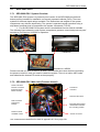
3.10.2 Transducer handling
The active area of the transducers must be protected against mechanical damages. Don’t put
the transducer on this (blue or black) area to avoid scratches or getting the transducer punctured. Some of the transducer housings have supports alongside the active area to make it
possible to place the transducer directly on flat and clean surfaces, see figure below.
SES-2000 transducer with streamlined housing and supports to protect the
active area (that is the blue area in the photograph).
The active area of the transducer has to be clean. Especially when operating in warm water
there might be some fouling that must be removed to prevent the transducer from overheating. Don’t use chemicals or sharp tools to remove the fouling; the transducer’s surface
must not be damaged. The active area of the transducer must not be exposed to strong
sunlight for a longer period since UV light affects the chemical and mechanical properties of
the material used. Thermal stress (e.g. putting sun-heated transducers into cold water) has to
be avoided as well.
Furthermore no paint, oil or grease should be put on the active area of the transducer. Hull
mounted transducers should be removed or protected by cover-plates when the ship is maintained and painted in the yard.
The transducer cable has to be protected against damages. The minimal bend radius of the
cable is about 20cm. Don’t use a cable with damaged insulation! The plug is not waterproof
and should be protected to avoid corrosion at the electrical connections. The cable is moulded non-removable to the transducer.
Innomar Technologie GmbH
SES 2000 User’s Guide
35
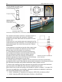
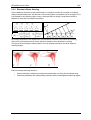
3.10.3 Transducer installation
In general the transducer installation should be made according to the following guidelines.
•
Transducer depth: The upper water layers are filled with small air bubbles, especially
in heavy seas. Air bubbles absorb acoustic energy and may block the desired acoustic
signal entirely. Therefore select a location as deep as possible for the transducers,
where the water is less aerated and you have a wider weather window.
•
Transducer location: Select a location as far away as possible from sources of noise.
For sub-bottom profilers normally the ship’s engine is the dominating noise source.
Prefer locations in the forward third of the vessel, which normally will provide less
aerated water, less noise and less turbulence. Heave will be lowest mid-ship since no
angular components are added. Avoid locations near the ship’s aft because of noise
(propeller and engine) and aerated water.
•
Bulbous bow: If the vessel has a pronounced bulbous bow, be aware that it will transport aerated water down. Tunnel thrusters in the bow will also transport aerated water
down in heavy seas. Accordingly, flush installations are more easily troubled by aerated
water than blisters and gondolas that protrude from the hull.
•
Objects protruding from the hull: Any objects protruding from the hull as well as holes
and pipe outlets generate turbulence and flow noise. Do not place the transducer in the
vicinity of such objects, and especially not close behind them. For the same reason, it is
very important that the hull area around the transducer face is as smooth and level as
possible. Even traces of sealing compound, sharp edges, protruding bolts or boltholes
without filling compound will create noise.
•
Portable mounting: For portable mounting, be aware of the need for a stiff connection
between echo sounder transducer and motion sensor. Also, be aware of limitations in
vessel speed as well as weather window.
•
Transducer inclination: Transducers should be mounted horizontally (parallel to the
water surface) to ensure best system performance, especially for narrow- beam subbottom profilers like the SES-2000 systems. A small positive inclination (bow up, max.
0.5°) is acceptable in order to ensure laminar water flow. Avoid negative inclination
since this may cause turbulences.
•
Acoustic coupling: To avoid structure-borne noise going from the ship’s hull into the
transducer, the transducer has to be decoupled acoustically by using rubber or other
damping material.
As said above, installations flush with the hull will often cause problems due to aerated water
going below the transducer. Therefore blisters or gondolas should be used for hull mounting.
Transducers for shallow-water SES-2000 systems are mostly installed over-the-side using a
pole. These transducers have bolts or holes on top of the transducer housing for mounting,
see figure below. More detailed drawings are given in the appendix.
An arrow on top of the transducer housing marks the forward direction.
For proper operation the transducer must be fixed firmly and vertically because of the narrow
sound beam. Do not use long pipes with small diameters that are vibrating when the ship is
moving.
The whole transducer must be covered by water all the time, even during rough sea!
Innomar Technologie GmbH
36
SES 2000 User’s Guide
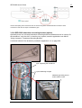
Transducer mounting sketch and “over the side” installation example
The transducer should be mounted on a position where no
screw water can go below the transducer. Getting air
bubbles from the bow water below the transducer must be
avoided, too.
If the survey is in very shallow water, the lowest point of the
vessel should not be the transducer. The sounding area can
easily be damaged if the vessel hits the ground or objects,
like boulders.
If the transducer is mounted on the side of the vessel, make
sure that the sound beam (the side lobes of the HF beam
pattern) does not hit the vessel’s hull, see figure.
To avoid interferences with the noise that is produced by
ship’s engine the transducer should be placed as far away
from the engine as possible. Since the engine (and the
propeller) is at the rear end of the ship, the transducer
should be placed at the front half of the ship. At small boats
the best place for the transducer is at the bow.
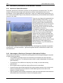
Transducer mounted “over the side”
with HF directivity
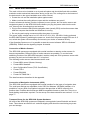
To avoid the impact of noise by vibrations onto the transducer it should be mechanically
decoupled from the vessel. Especially the steel-to-steel connections on the flange and on the
pipe should be decoupled using elastic material like rubber, plastics or wood.
To reduce noise caused by the mains generator the transducer’s housing should be electrically connected to the SES-2000 main unit by an additional ground wire.
More advise how to avoid noise going to the transducer is given in chapter 7.1 on page 109.
There are two application notes available, dedicated to transducer installation in general as
well as mounting transducers on small boats:
•
AN-01 “Installation of Transducers for INNOMAR’s SES-2000 sub-bottom profilers”
•
AN-04 “Operating SES-2000 Sub-bottom Profilers on Small Boats”
Innomar Technologie GmbH
SES 2000 User’s Guide
37
Acoustic decoupling of the transducer from the vessel using elastic material between the steel-to-steel
connections. Note also the ropes to stabilize the pipe.
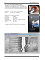
3.10.4 SES-2000 transducer mounting bracket (option)
Optionally there is a universal transducer mounting bracket available that can be used to fix
the transducer “over the side” on small survey vessels, see also application note AN-06
“Using INNOMAR’s Transducer Mounting Bracket”.
A technical sketch of the bracket is provided in appendix A.1.2 on page 202.
pipe supporting the transducer
ropes stabilizing the pipe
additional grounding wire to
reduce electric noise
Innomar Technologie GmbH
38
SES 2000 User’s Guide
3.11 Main Unit Installation
The main unit has to be installed on a dry and safe place and should be fixed with a suitable
method to avoid mechanical destructions during rough sea. The cooling slits on the bottom of
the device and on the upper backside must not be covered.
Protect the unit and the installation place against water!
Make sure that the cooling slits are open and the ventilators can get air!
Connect all external devices (monitor, keyboard, mouse, printer, but not motion sensor and
navigation system!) to the SES-2000 device before you plug the power cable into the main
unit. Use only the according plugs and sockets.
Plug in the connectors that provide navigation data (usually GPS) and motion sensor data
after the computer has booted and Windows is running.
Do not plug and unplug connectors while the system is running!
The power supply voltage has to be 115–230 V AC +5%/-10%, 50–60Hz. Having activated
the SES-2000 system by switching the power on, check first if all power supply LEDs are lit. If
not, switch the system off immediately and contact your dealer or INNOMAR directly.
If the Operating System runs, it is possible to start the control software “SES for Windows”
(SESWIN). Please see the regarding chapter for details.
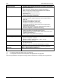
Connection of Motion Sensors
The SES-2000 systems are equipped with a serial interface to attach a motion sensor for
heave compensation. Different types of motion sensors are possible. To use the beam
stabilizing function of the SES-2000 standard, medium, deep and ROV systems a sensor with
accuracy for pitch and roll better than 0.5° is required.
The following motion sensor data formats can be used:
•
Format MRU normal (Seatex, Norway)
•
Format MRU Standard
•
User Configurable Format (TSS, Great Britain)
•
Format TSS-1
•
Format EM-3000
•
Format OCTANS Std 1
The data formats are described in the appendix.
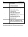
Connection of Navigation Instruments (GPS)
The SES-2000 systems are equipped with a serial interface for the input of navigation data.
The serial port settings are adjustable via the 'SES for Windows' (SESWIN) software. It is
possible to use any kind of navigation instrument that provides an ASCII output for the
position data. Possible data formats are NMEA compatible formats or plain text. There is no
hand shaking mechanism required. For the set-up of the data extraction see section 5.11.1 on
page 77.
Transport Boxes for the SES-2000 System Hardware
All items of the SES-2000 systems are shipped in strong plastic boxes filled with anti-shock
foam. These boxes are fitted for air- and sea shipping and should be used during any transport and storage.
Innomar Technologie GmbH
SES 2000 User’s Guide
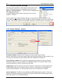
39
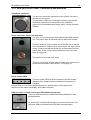
3.12 SES-2000 Front Panel: Connectors and Switches
Transducer connector
You have to connect the transducer to the system unit before
switching on the power!
The transducer cable has a sea water resistant polyurethane
sheet and is moulded non-removable to the transducer
(minimum recommended bend radius: static: 100mm, dynamic:
220mm).
Power connector, switch and main fuse
You have to connect a power cable with the SES-2000 system
unit. The power cable is delivered with the SES-2000 system.
The main switch is used to switch the SES-2000 unit on and off.
Prior to that the AC cable must be connected to the ship’s power
supply. Please note that the switch will not disconnect from the
power lines. There is high voltage inside the unit if the power
cable is plugged in!
The system is fused with 10A (slow).
There are more fuses located behind a plate in the rear panel to
protect the transmitters, see section 3.13 on page 43.
Power control LEDs
There are power LEDs in the front panel of the SES system,
indicating if all voltages that are needed by the system are
available.
If these LEDs are not lit after switching power on, please switch off the system and
disconnect from mains immediately and contact INNOMAR.
USB connector / remote control port (SES-2000 compact only)
There are USB connectors to attache external harddisks for data
beckup/transfer.
An external PC or Notebook that will be connected to the main unit
using the USB port operates the SES-2000 compact system.
Innomar Technologie GmbH
40
SES 2000 User’s Guide
Navigation input
The SES-2000 system has an RS232 input for navigation data. The
navigation data can be received from a (D)GPS system or a ship
information system, see section 3.14 on page 44.
The input is NMEA compatible or can be configured to any ASCII format. The properties of
the navigation input, like Baud rate, Data Bits, string synchronising has to be set within the
SESWIN software "Main Menu – Options – System Interfaces – SIS"
Motion Sensor input
The system has a RS232 serial input for the data from a motion
sensor. An external power supply for the motion sensor is necessary.
The properties of the navigation input have to be set within the
SESWIN software "Main Menu – Options – System Interfaces –
Motion Sensor"
The SES-2000 compact and light systems can use the heave information only, but the SES2000 standard / medium / deep / ROV systems use the roll-, (pitch-) and heave information.
For motion sensor installation see section 3.14 on page 44.
Depth output (Option)
The SES-2000 systems have an RS232 output for the water depth
values obtained from the HF- and LF-channel. The navigation data
can also be included in the output string.
The output is NMEA compatible and can be configured as a comma separated ASCII string.
The properties of the Depth output have to be set within the SESWIN software "Main Menu –
Options – System Interfaces – Output"
PC-Network
The PC network interface can be used for data transmission and
system remote control.
Mouse and Keyboard
To control the system a mouse (PS/2) and a keyboard (PS/2) have to
be connected to the system unit. Both will be delivered with the
system.
Monitor / Video Output
In addition to the built-in TFT-Display (not SES-2000 compact), you
can connect an external monitor to the video output of the system unit.
An external power supply is necessary.
Innomar Technologie GmbH
SES 2000 User’s Guide
41
TFT-Display
The SES-2000 main unit (not SES-2000 compact) will be delivered with an integrated 10.4”
TFT-display. The resolution is 800 x 600 pixel. In addition to the TFT-Display, you can also
use an external monitor with the system unit by connecting it to the Monitor Output of the
system unit.
Display Control Buttons (not SES-2000 compact)
There are four buttons to control the properties of the
built-in TFT-display (brightness, contrast etc.).
System Hotkeys (not SES-2000 compact)
The main functions to control the system during a survey are implemented as hotkeys at the
front of the system unit (not SES-2000 compact). Accessible functions are:
SND - switch transmitting on/off
REC - switch recording on/off
PRN - switch printing on/off
CHN - switch channel HF/LF
FRQ - change the LF-Frequency
PLS - change the LF-Pulse length
MRK - set marker, which will be stored and printed in the echo print
CNT - set profile counter
Printer
If you want to print your online calculated echo prints during
the survey you have to connect a printer to your computer. You
can also connect it while the system software is running. The
status of the printer is shown in the status bar of the SESWIN
software.
The printer output has to be configured within the SESWIN software, see section 5.11.6 on
page 84. For on-line echogram printouts, only a limited number of printer models can be
used, see appendix A.5 on page 229.
GND Connector
The SES-2000 system has a female banana ground connector to apply a
separate ground connection to the transducer. Depending on the power
supply on board of the vessel, sometimes disturbances (noise) occurring
in the receiving signal can be reduced by the additional GND-connection.
Innomar Technologie GmbH
42
SES 2000 User’s Guide
Analogue Out / Analogue In
The Analogue Output (BNC) is the output of the band limited LF-signal
(secondary frequency). The centre frequency and bandwidth of the signal
is set according to the chosen transmission pulse frequency and pulse
length. The voltage range of the analogue output signals is ±10V.
The (optional) Analogue Input (BNC) can be used to feed signals from other sources to the
SES-2000 system. The input signal must be in an amplitude range of ±5V. The bandwidth for
the signal analysis is 2–22 kHz, depending on the transmitter settings chosen within the
SESWIN software. If you want to use the analogue input, you should use an external trigger
pulse as well, see section 6.2 on page 100
Trigger In / Out
Trigger IN
External pulses are fed to this input
•
to trigger the shots ('external synchronization') or
•
to create marks on the screen ('external marker events')
Trigger OUT Output of pulses to trigger other systems. For some system variants there is
a LED next to the Trigger OUT connector flashing every time a sync pulse is
generated (new systems only).
When SES-2000 is set to external synchronisation without feeding an appropriate
pulse sequence to "Trigger IN", neither the LF- nor the HF-window will show any
incoming echo data. Always remember that when you invoke SES-2000 and
"nothing happens".
For a detailed description of the trigger options refer to section 6 on page 99.
SES-2000 medium / deep Interconnection Link
To connect the main unit and the extension unit of the SES-2000 medium and SES-2000
deep systems, there are two link-cables (point-to-point connections) used. The cables are
about 2m long.
main unit
extension unit
Link connectors at the front panel
Innomar Technologie GmbH
SES 2000 User’s Guide
43
3.13 SES-2000 Rear Panel
At the SES-2000 rear panel there is some information about the system and additional fuses:
Product Type / Serial Number / Manufacturing Date
Fuses
Behind a small cover plate there are some additional fuses that protect
the transmitter’s power supply. Each fuse holder contains the fuse in
use and a spare fuse.
Distance Sensor
Some SES-2000 systems are optionally equipped with special
housings for rough environmental conditions.
These units have a distance sensor in the rear panel to prevent
running the system without removing the rear cover. It will not be
possible to activate the transmitters, if the cases are closed.
You have to remove the covers from the front side and from the backside and you must
realise a distance between backside of the unit and wall of about 15 cm in minimum.
Innomar Technologie GmbH
44
SES 2000 User’s Guide
3.14 Installing additional Sensors
3.14.1 Installing / Testing the Motion Sensor
The SES-2000 systems are equipped with a serial interface to attach a motion sensor. For
the motion sensor an external power supply is necessary. INNOMAR usually provide a power
supply together with the motion sensor.
The SES-2000 compact and light systems can use the heave information only, but in the
SES-2000 standard, medium, deep and ROV systems the roll-, (pitch-) and heave information
is used (depending on the transducer type). For these systems a sensor with accuracy for
pitch and roll better than 0.5° should be used. The recognized data formats are described in
the appendix.
The sensor has to be fixed firmly and must not vibrate. It should be placed as close as
possible to the SES-2000 transducer. If that is not possible, make sure the lever arm
correction of the motion sensor is set correctly. It is also important to ensure the right
orientation of the motion sensor related to the transducer.
After installing the motion sensor some settings are necessary within the SESWIN software
(Main Menu – Options – System Interfaces – Motion Sensor), see section 5.11.4 on page 82
of this manual.
To check the mounting orientation, you can perform the following motions with the sensor and
observe the changed data in the MS window in the SESWIN screen:
•
lift the sensor
→ heave value goes negative
•
tilt to starboard (right looking forward)
→ roll value goes positive and increases
•
tilt backwards (transducer goes bow up)
→ pitch value goes positive and increases
If heave values have the wrong sign, this can be adjusted within the SESWIN motion sensor
dialog, see section 5.11.4 on page 82.
The performance of the motion sensor can be improved by providing additional information
like heading/course or speed of the ship. Therefore some motion sensors are able to use
NMEA sentences sent by a GPS receiver to get the necessary information. Often the VTG
sentence is used to obtain the speed of the vessel.
For the MRU-Z motion sensor INNOMAR provides a splash-water proof
housing intended to protect the MRU placed outdoor (e.g. on deck). The
housing has no depth rating and must not be installed under water! There
is a mounting bracket with 4 holes placed on the motion sensor housing to
ease the mounting near the transducer.
Some more hints how to install and setup a motion sensor to work with the SES-2000
systems are given in section 7.3 on page 113.
3.14.2 Installing GPS
The SES-2000 systems are equipped with a serial interface to attach a GPS device. To avoid
position errors caused by antenna offsets, the GPS antenna should be placed on top of the
transducer. If this is not possible, an antenna offset correction can be applied within the
SESWIN software (Main Menu – Options – System Interfaces – Offsets), see section 5.11.8
on page 86. For this accurate and reliable heading information is necessary.
To use the position data delivered by the GPS device within the SES-2000 systems, some
settings have to be made within the SESWIN software (Main Menu – Options – System
Interfaces – SIS), see section 5.11.1 on page 77.
Innomar Technologie GmbH
SES 2000 User’s Guide
45
3.15 SES-2000 power supply requirements
3.15.1 Mean power consumption
The power consumption of the SES-2000 SBPs depends on
•
pulse repetition rate (How many pings are transmitted per second?),
•
transmission frequency and
•
transmission pulse length.
In general the power consumption is a function of the pulse duty cycle, but for lower
frequencies the inrush current will be higher than for higher frequencies at the same duty
cycle. The duty cycle DC is calculated as follows:
DC =
pulses
• PPS
frequency
(frequency in Hz; PPS = pulses per second)
All these values can be obtained from the SESWIN software, see screenshots below.
Innomar Technologie GmbH
46
SES 2000 User’s Guide
Power Consumption (W)
450
400
350
300
250
y = 14903 x + 215
200
0,000
0,002
0,004
0,006
0,008
0,010
0,012
0,014
0,016
Duty Cycle
Power consumption of the SES-2000 standard system depends on the duty cycle. For this system the maximum
power consumption is less than 450 Watts even while using long low-frequent sound pulses at high pulse rate.
3.15.2 Power-on inrush current
There are switched voltage converters used within the SES-2000 units to ensure a wide input
voltage range (115-230V AC +5%/-10%, 50-60Hz). These power supply modules draw a
strong surge current during power-on for a short time. The figure below shows the.
Inrush Current (A)
30
25
20
15
10
5
0
-0,1
0,0
0,1
0,2
0,3
0,4
0,5
Time (s)
Inrush current measured with the SES-2000 standard system (power supply 220V). The figure shows strong
current for a very short time (less than 10ms).
3.15.3 Conclusions
The mean power consumption of the SES-2000 SBPs depends on different parameters. The
maximum values are given in the table below. There is a strong switch-on inrush current that
may blow fast fuses. Therefore the power supply should be use slow fuses with a current
rating given in the table below. All values are given for a power supply voltage of 230V. Lower
voltages will require higher currents. The power rating may be slightly different at other
voltages as well due to changes in efficiency of the power supply modules used within the
SES systems.
SES-2000
Power consumption
Mains Fuse
compact
< 250 W
10 A / slow
light
< 400 W
16 A / slow
standard
< 500 W
16 A / slow
medium
< 900 W
20 A / slow
deep
< 1500 W
25 A / slow
ROV
< 500 W
16 A / slow
Innomar Technologie GmbH
SES 2000 User’s Guide
47
4 Installing the SESWIN System Software
There is system software, called “SES for Windows” (or SESWIN for short), that is delivered
together with the SES-2000 system to manage the system’s on-line operation, data
acquisition as well as data replay. This software is pre-installed on the built-in control PC of
the SES-2000 system (or the notebook computer optionally delivered with the SES-2000
compact system).
To ensure proper operation of the system, do not change the settings of the BIOS and the
Windows OS and do not install any other software packages and device drivers.
There is a backup of all the delivered software in a folder named “SBackup” on hard disk “C”
of the computer delivered by INNOMAR.
4.1
Installing SESWIN software
If it should become necessary to reinstall the SESWIN software, please follow the procedure
given in section 7.5 on page 119. It is advisable to have an administrator account for that
purpose.
Before starting the SESWIN software for the first time, you have to run the SES configuration
tool first, see next section!
4.2
Initial Setup using the SES Configuration Tool
The SES-2000 systems are delivered with a separate configuration tool (sesconfig.exe) for
basic system settings that has to be run before starting the SESWIN software for the first
time.
4.2.1 Password settings
When the SES Config is invoked the very first
time, a window shows up asking for a master
password. The SES-Master later on will be
able to create new user profiles and passwords for other users.
This LOGIN window always shows up
automatically when the SESWIN software
is invoked. Password protection of the
SESWIN software can be enabled and
disabled via “Options – Login at start up”
in the SESWIN main menu.
Innomar Technologie GmbH
48
SES 2000 User’s Guide
4.2.2 System Settings
Application Mode
For the SES-2000 compact system ‘External PC (selectable COM Ports)’ must be chosen.
For all other SES-2000 systems 'Stand Alone System (fixed COM ports)’ should be used.
COM port settings (SES-2000 compact only)
Linking SES-2000 Compact and your PC with the USB cable provides the PC with two
additional COM ports ('Data Port' and 'Control Port'; both <COM32) that have to be
configured properly:
•
To see which COM ports are available, please see the “Ports” tab of this dialog. Using the
obtained information you can assign the ports in the “System” tab.
•
It is also possible to use the 'Detect Data and Control Port' button to assign Data and
Control ports. A window will show up and the data port usually is detected rather quickly,
it might take a bit longer to find the control port.
•
The ports for 'SIS Interface' and 'Depth Values' are COM ports of the customer's PC.
They have to be selected manually.
If there are problems to detect the ports, please see section 7.4 on page 115 for more hints to
setup the SES-2000 compact software properly.
Here is a short procedure to check if all COM ports have been set properly after starting the
SESWIN system software (serial port settings have to be made before in the SESWIN
options):
•
The SESWIN echoplot area on the screen should be scrolling. (Data port OK)
•
Vary the range; the scrolling is either faster or more slowly. (Control port OK)
•
Connect the GPS device to the COM port that has been chosen as the SIS Interface.
Then position data should appear in the “SIS” window (left bottom corner of the screen).
For this the interface has to be configured properly, see section 5.11.1 on page 77.
•
Use HyperTerminal (or a similar program) to see what data comes out of the “Depth Out”
serial port. The depth output interface has to be configured before, see section 5.11.2 on
page 80.
Innomar Technologie GmbH
SES 2000 User’s Guide
49
Printer Interface
The printer interface can be selected between LPT port and MS Windows Default printer. This
can be either a USB port printer or a network printer. If an USB or network printer is used, the
driver has to be installed properly. In any case the printer model has to be supported by
SESWIN. How to set up printing is discussed in section 7.9 on page 124.
Printer Port Settings
Usually the parallel port of a PC is at address 0378h. If you are using a LPT port with another
port address, then you have to key in this address instead.
External SIS data source
If for any reason no positioning system can be connected directly via a normal COM port, it is
possible to read SIS data from a file (only the first line of the file will be evaluated). This file
may be located on a network and updated regularly from external software with SIS data
strings. All settings regarding the SIS interface (SESWIN main menu – Options – System
Interfaces – SIS) are applied in the same way as for the COM port input.
COM port devices
The MS Windows OS has a built in feature to detect COM port devices automatically. Sometimes devices are detected incorrectly, e.g. GPS receivers are often detected as a mouse
device, when connected during boot up of the PC.
With the COM port settings of the SESCONFIG tool you can disable the automatic detection
of COM port devices either for all COM ports or for the COM ports used by the SESWIN
application.
It is recommended to disable auto detection for SES ports at least.
4.2.3 Network Settings
It is possible to operate the
SES-2000 system via TCP/IP
network.
Innomar Technologie GmbH
50
SES 2000 User’s Guide
Network Settings
Depending on the settings in the “Network” tab additional entries in the SESWIN “Options”
menu will appear to activate corresponding network operation modes.
'No network operation’:
The SES-2000 system is running standalone
(“normal” operation)
'Network operation as Server':
The SES system itself in remote control mode
'Network operation as Client':
The remote PC requires the same SESWIN software,
but it must be configured as a client
Network Options
If the checkbox for the automatic start of the Network Server is checked, the SESWIN
software will switch into server mode on start-up. This is useful if the main unit is located in a
server room or if you are using the SES-2000 ROV system.
4.2.4 COM Ports Information
This tab can be used to check
which COM ports are available
on the system. Some port
properties are obtained and
displayed as well.
This function should be used
for assigning COM ports
manually in the “System” tab of
this dialog.
4.2.5 Documenting SES Configuration settings
Screen dumps of all settings may be saved automatically by pressing the button on the lower
right corner of the dialog.
Innomar Technologie GmbH
SES 2000 User’s Guide
51
5 SES for Windows (SESWIN System Software)
5.1
The SESWIN screen
Main Menu
Button Bar / Hot Keys
Level Display
Depth Display
Parameter
Menu
Depth
Ruler
Echo Plot
Screen
Monitoring
Windows
Status Bar
Echo plot display
Online output of calculated echogram. Scrolling speed depends on
the range settings, the resulting ping rate and process parameters.
Depth display
Display of water depth measured by HF channel
Monitoring
Windows
SIS:
Display of navigation data
MS:
Display of motion sensor data
Signal:
Display of echo envelope
MAP:
Display of track plot
Level display
Displays signal amplitude of LF- and HF-channel
Depth ruler
A depth scale is displayed. The depth values are calculated based on
a given constant sound velocity.
Parameter menu
Setting of hardware parameters (e.g. choosing frequency and pulse
length, setting the amplifiers)
Status bar
Display of essential system settings and status display for the system
Main menu
(pull down menus)
System configuration, interface configuration, help.
Button bar /
Hotkeys
Setting of most important features for system mode
(e.g. switching on/off transmitting, data recording, printing)
Innomar Technologie GmbH
52
5.2
SES 2000 User’s Guide
SESWIN Main Menu
5.2.1 Program Menu
“File Browser” and “File Cutter” are file-handling tools that
are only available in file mode. They are described in detail
in section 5.14 on page 93.
“Capture Window” creates a screen shot of the SESWIN
window and stores the picture in BMP or GIF format.
5.2.2 Options Menu
The “System Settings” and “System Interfaces”
have to be set properly before the survey starts,
see sections 5.10 on page 66 and 5.10 on page
66 respectively. These settings were called
“General Options” in older SESWIN versions.
Depending on the network settings made in the
SES Configuration tool (see section 4.2 on page
47) this menu contains different entries for the
network options, see section 5.12 on page 87
The SIS and MCP monitor are described in
section 5.13 on page 92.
5.2.3 Help Menu
The “Help” menu items are only available in file
mode.
The “System Info” box gives some information useful
for troubleshooting, like serial numbers, software
versions and memory space.
The “About” box shows the software version and the
SES-2000 serial number, see screenshot.
Innomar Technologie GmbH
SES 2000 User’s Guide
5.3
53
SESWIN Button Bar / Hot Keys
5.3.1 Overview
File Mode - F2
Exit Program - Alt+F4
System Mode - F2
Marker - F12
Open File - F3
Next Profile - F11
Transmitter- F4
Echoprint Mode- F10
Record - F5
Split View - F9
Printer - F6
HF Channel - F7
Quick Controls
LF Channel - F7
File Mode
[F2]
Displays files which have been recorded previously
System Mode
[F2]
Activation and control of the equipment during the survey
Open File
[F3]
Selects a file to open it (in File Mode)
Transmit
[F4]
Switch transmitters on/off (in System Mode)
If the rear cover of the water protected case is closed, this button
is disabled and the transmitter cannot be used!
Record
[F5]
Switch data record on/off (in System Mode)
Printer
[F6]
Switch printout of data actually displayed on the screen on a
printer connected to the system on/off
Quick Controls
Toggles full and reduced Parameter Menu. Reduced menu
(“Quick Controls”) may be used during data acquisition.
LF-Channel
[F7]
Displays the signals of the low frequency (LF) channel
HF-Channel
[F7]
Displays the signals of the high frequency (HF) channel
Split View
[F9]
Displays data of HF- and LF-channel simultaneously
Echoprint Mode
[F10]
Toggles echoprint view: amplitude envelope or amplitude changes
(“High Resolution”) of the received signal
Next Profile
[F11]
Increment of profile number by 1, starts a new file if record is on,
starts a new page if the printer is on
Marker
[F12]
Marks the echogram at the actual position and increases mark
counter by 1
Exit
[ALT]+[F4]
Quits program
Innomar Technologie GmbH
54
SES 2000 User’s Guide
5.3.2 File Mode [F2]
Pressing this button activates the replay feature of the SESWIN program. Files recorded
before can be displayed. This mode is generally used in the office when the survey has been
finished and someone wants to look at the data or print the data again and the ISE software is
not available. One should use the ISE post-processing software instead.
5.3.3 System Mode [F2]
Pressing this button activates that part of the program that controls the SES system and
records and prints the data just received. This mode is used online, i.e. while surveying.
5.3.4 Open File [F3]
This is only enabled in File Mode to replay, to process and to print stored data. The standard
MS Windows file open dialog will appear for the selection of data files (*.ses). It is possible to
select not only one but also a group of files for replay.
5.3.5 Transmit [F4]
The Transmit button switches the transmitter on/off. It is only enabled in System Mode. If the
Transmit button is activated, the transducer will transmit the frequency and pulses as defined
in the „Transmit“ parameter menu.
If the Transmit button is set, the (optional) green “SND” LED at the front panel is lit. The
(optional) system hot key “SND” at the front panel can be used to switch on/off the transmitter
as well.
The Transmit button will be disabled if the backside cover of the (optional) water-protected
case is closed during the System Mode.
The transducer must be connected to the SES-2000 System unit and placed in
water before the transmitters are switched on. Operating the transducer in air may
cause serious damages!
Data Recording is not switched on/off automatically with transmitter on/off!
5.3.6 Record [F5]
The Record button is used to switch on/off the digital recording of the received echo data.
Also the data from the navigation system and the motion sensor will be recorded when the
Record button is pressed. The actual file name will be shown on top of the application
window.
If the Record button is set, the (optional) green “REC” LED at the front panel is lit. The
(optional) system hot key “REC” at the front panel can be used to switch on/off the data
recording as well.
5.3.7 Printer [F6]
If a printer is connected to the system for online prints of the calculated echograms, the
printing can be switched on/off using this button.
If the Print button is set, the (optional) green “PRN” LED at the front panel is lit. The (optional)
system hot key “PRN” at the front panel can be used to switch on/off the printout as well.
5.3.8 Quick Controls
During data acquisition usually only a limited number of controls are necessary (e.g., gain
settings and range start). Pressing this button changes the normal Parameter Menu to a
reduced one that give only access to a limited number of settings (“Quick Controls”).
Innomar Technologie GmbH
SES 2000 User’s Guide
55
5.3.9 LF-Channel [F7]
If the LF-channel button is set, the LF-signals will be printed and shown on the display. In any
case both channels (HF and LF) will be recorded.
With the (optional) system hotkey “CHN” you can toggle between the HF- and LF-channel.
5.3.10 HF-Channel [F7]
If the HF-channel button is set, the HF-signals will be printed and shown on the display. In
any case both channels (HF and LF) will be recorded.
With the (optional) system hotkey “CHN” you can toggle between the HF- and LF-channel.
5.3.11 Split View [F9]
If SplitView is activated, HF and LF data are displayed simultaneously on the screen. The
echogram displayed on the right side of the screen corresponds to the channel activated by
the buttons LF-Channel or HF-Channel. The other channel is displayed on the left side of the
screen.
In Beam Steering Mode the echoprints of the first three beam angles as defined in “Main
Menu – Options – System Settings – Beam Steering” are displayed on the screen
corresponding to the channel activated by the buttons LF-Channel or HF-Channel. The
signals from Angle 1 are shown in the right window, from Angle 2 in the centre window and
from Angle 3 in the left window.
5.3.12 Echoprint Mode [F10]
For processing the echo data there are two display modes available, see section 9.6 on page
192. Clicking this button toggles the display between colour-coded envelope of the received
echo (“Amplitude”) and changes in the amplitude of the received signal (“High Resolution”).
5.3.13 Profile Counter
Press the Profile Counter button to increase the profile number (increment by 1). At the same
time the recording and printing will be restarted if active. You can increase the profile number
counter also with the (optional) system hotkey “CNT” on the front panel.
The start number of the Profile Counter is set in “Parameter Menu – General”.
5.3.14 Marker
Press the Marker button to set a marker and increase the marker counter. A vertical line with
the marker counter will be drawn on the screen. This feature is useful to label interesting
features in the data and looking for them during post-processing. There is no additional
annotation available within the SESWIN software; the only reference stored in the data file is
the marker counter.
Markers can be set also with the (optional) system hotkey “MRK” on the front panel.
The Marker Counter is reset to zero in “Parameter Menu – General”.
5.3.15 Exit
Press the Exit button to leave the program. The transmitter will be switched off, the recording
and printing will be stopped.
You can leave the program also via “Main Menu – Program – Exit”.
Innomar Technologie GmbH
56
SES 2000 User’s Guide
5.4
SESWIN Level Display
These level meters can be used to adjust the amplifier settings (Parameter Menu – Gain).
The chosen gain is okay if the red LEDs of the HF- and LF-channel flash only occasionally.
The two single LEDs on the right side are indicating the amplification of the raw and unfiltered
signal and are used to indicate an amplifier overload. Red colour should be avoided for these
LEDs.
5.5
SESWIN Depth Display
The online calculated water depth from the HF channel is displayed in the upper right corner
of the SESWIN window.
The depth calculation is based on the transducer depth and sound velocity (see “Main Menu
– Options – System Settings – System”) and can be adjusted to the actual conditions of the
measurement via “Parameter Menu – Depth”.
5.6
Monitoring Windows
There are four windows displaying different data:
•
SIS displays the first 6 (of 8) values imported from the navigation (GPS) data as
defined via “Options – System Interfaces – SIS”. SIS values 7 and 8 are displayed if
the mouse cursor rests on SIS value number 6.
•
MS displays data received from a motion sensor. Motion sensor data import is defined
via “Options – System Interfaces – Motion Sensor”.
•
SIG displays the envelope (amplitude) of the received echo signal. This window can
be used to adjust the amplifier settings.
•
MAP displays a map with track information and optionally defined profile lines and
target positions. Settings are made via “Options – System Settings – Map”. It is
possible to zoom into the map and to highlight run lines and targets.
Innomar Technologie GmbH
SES 2000 User’s Guide
5.7
57
Status Bar
The status bar is situated on the bottom of the SESWIN window.
The upper line of the Status Bar shows information about:
•
the chosen range which is displayed on the monitor or printer and recorded to file,
•
the selected LF-frequency and LF-pulse length,
•
the actual profile number and
•
the actual file size (System Mode) or the replay position in the data file (File Mode).
This is not shown in the figure above. If raw (full waveform) data is acquired, file size
of both files is displayed.
The lower line of the Status Bar shows:
•
the system date and time (can be synchronized to GPS time automatically via
“Options – System Interfaces – SIS – Time Synch.”)
•
trigger source (INTernal / EXTernal synchronization as set via “Options – System
Settings – System”)
•
the status of the built in HD and the status of the connected external devices, such as
printer (PRN), motion sensor (MS) and navigation system (SIS).
The coloured LEDs in the status bar are used to monitor the status of the connections to
peripherals. The colours are Green = OK, Yellow = Warning and Red = Not Working.
•
PRN: Printer Information. Red colour (as above) will mean no printer connected, out
of paper etc.
•
HD / NET: Hard Disc space. This shows the space remaining on the hard disc the
data is being recorded on to. The colour will change to yellow with 250MB remaining,
and then go to red when close to empty. HD refers to the local hard disc while NET
refers to the hard disc of a remote-controlled system.
•
MS: Motion Sensor. The colour will be yellow if there is a problem such as the MS
string is not recognised or maybe vessel movements are too abrupt to be compensated for (Instable Flag!), and red if the motion sensor is unplugged or not working.
If the “ignore instable flag” mode is enabled in the SESWIN “Options – System
Interfaces – Motion Sensor” dialog, this status LED is encircled yellow (SESWIN 1.7.2
or higher).
•
SIS: Ship Information System (navigation data). The will be yellow if there is data
coming but is not recognised (e.g. due to wrong baud rate). The colour will be red if
there is no incoming data.
•
Case: If the system has a water-protected case, the rear cover must be removed
before using the system. Red colour indicates that a closed cover is detected and the
transmitter cannot be switched on!
•
MCP: Multi Purpose COM Port (see section 5.11.3 on page 81). The warning colour
will be yellow if there is data coming in but is not recognised. The colour will be red if
there is no incoming data.
Innomar Technologie GmbH
58
5.8
SES 2000 User’s Guide
Parameter Menu / Control Parameters
Options, parameters and values selected in the parameter menu
directly control the quality of the data collected and displayed. A
changed parameter is sent to the hardware system and takes effect
at once.
The Parameter menu described in this section is visible only if the
“Quick Controls” button is not pressed. Otherwise a reduced menu is
available, providing quick access to all parameters that have to be
changed during data acquisition, see section 5.9 on page 65.
Since some parameters depend on each other, limits for the available ranges are sometimes not static but set by the software to ensure a reliable operation of the SES-2000 system.
To change the parameters a mouse or trackball can be used or you
can use the following keys on the keyboard:
•
The focus can be set from one tab to the other by
[Ctrl]+[TAB] or [Shift]+[Ctrl]+[TAB].
•
The focus of the items within one tab of the parameter menu
can be changed by the [TAB] key or [Shift]+[TAB].
•
Values can be changed using the [up/down] arrow keys
(small steps) or the [page up/down] keys (large steps).
In the following description the large steps are given in
parentheses if any.
You may also use the wheel of a wheel-mouse to change the
selected parameter.
During data collection emphasis should be placed on acquiring good data by adjusting range,
frequency, pulse length and gains properly.
5.8.1 General
The first boxes are used to enter header information for a survey, i.e.
vessel name (Ship), survey area (Travel) and run-line (Area). Each
string has a maximum length of 20 chars. This information is stored
within the data files, displayed on playback and also on the printed
record. The Area name may be used as file name prefix.
On entering new information, the Apply New Profile button flashes,
and the new information becomes valid after pressing this button.
The next run-line can therefore be entered during a present survey
line and then applied just before the start of the new line.
The Profile box can be changed with each survey line, this may be
useful during a grid survey. (Range: 1 – 999)
The Reset Manual Marker button will reset the number of a manual
marker back to zero. The manual marker numbers automatically
increment with each new marker, see also section 5.3.14 on page
55.
Innomar Technologie GmbH
SES 2000 User’s Guide
59
5.8.2 Transmit
This tab sheet is used to set the frequency and pulse length of the
LF channel and to activate special transmit modes. Frequency and
pulse length chosen during data acquisition are final, they affect the
recorded data directly!
The HF frequency is fixed to 100kHz (35kHz for the SES-2000 deep
system). The HF pulse length is same as set in this menu for the LF
pulse length.
The LF Frequency (range: 4–15kHz; 2–7kHz for the deep system)
has to be chosen depending on the survey task. Lower frequencies
will achieve greater penetration than higher frequencies, but with
reduced resolution. Higher frequencies will achieve better resolution,
but with reduced penetration. Usually higher frequencies are used
due to better efficiency and better signal to noise ratio and better
resolution.
A good starting point for usual survey work is in the middle of the
range given.
LF-Pulses represent the number of cycles of the LF frequency that are transmitted. The
energy of the transmitted signal is increased if the number of pulses is increased. That
improves the signal-to-noise ratio but decreases the resolution. The available range depends
on the chosen frequency. The number of pulses should be as small as possible, if the
detection of small reflectors or the resolution near the sediment surface are of high priority,
but the higher bandwidth will be more prone to noise. A good starting point is in the middle of
the range.
Special Transmit Modes
For some systems there are several special transmit regimes/modes available:
•
High Energy Mode: used for deeper water (range start >50m) to enable extra-long
transmit signals. Cannot be combined with “Multi Frequency Mode” and “High Pulse
Rate Mode”. The “High Energy Mode” is disabled at pulse repetition rates higher than
15 pulses per second.
•
Multi Frequency Mode: used to transmit consecutive pings with different centre
frequencies and/or pulse lengths. The settings for this mode have to be made in “Main
Menu – Options – System Settings – Multi Frequency”, see section 5.10.8 on page 73.
This Mode can only be combined with “Allow High Pulse Rate” option.
•
Dual Range Mode: used to collect data for an extended range. The settings for this
mode have to be made in “Main Menu – Options – System Settings – Dual Range”,
see section 5.10.9 on page 74. This Mode can only be combined with “High Energy
Mode”.
•
Beam Steering Mode: Toggles beam steering on/off. The settings for this have to be
made in “Main Menu – Options – System Settings – Beam Steering”, see section
5.10.7 on page 72. Can only be combined with “High Energy Mode” and “Allow High
Pulse Rate” option.
•
Allow High Pulse Rate: At shallow waters and in small ranges the pulse repetition
rate can be increased. Pulse Length is limited in this mode. This mode can be
combined with “Multi Frequency” and “Beam Steering” modes only.
Innomar Technologie GmbH
60
SES 2000 User’s Guide
•
Deep Sea Pulse Mode: This allows high ping rates even at deep-water areas. The
mode is often used for deep-water survey (range start > 50m), since the increased
ping rate will give much higher data quality and resolution, see section 9.5.4 on page
191. Can be combined with “High Energy Mode” and “Burst Mode”. “Deep Sea Mode”
is possible wit internal trigger only. It will not work correctly if the system is triggered
externally. Some more information is given in section 6.4 on page 107.
•
Burst Mode: This is a special Deep Sea Pulse Mode, intended for reducing
interference if SES-2000 sub-bottom profilers are operated with other acoustic
equipment simultaneously, see section 7.13 on page 139. The duty cycle has to be
set up in “SESWIN main menu – Options – System Settings – Synchronisation”, see
section 5.10.2 on page 67. Can be combined with “High Energy Mode”. “Burst Mode”
is possible wit internal trigger only. It will not work correctly if the system is triggered
externally. Some more information is given in section 6.4 on page 107.
•
Chirp Mode: allows the transmission of a fixed Chirp (LFM) signal over the complete
range of centre frequencies (option for SES-2000 medium and deep systems only!)
Can be combined only with “Deep Sea Pulse Mode” and “Burst Mode”. The ping rate
is limited due to the longer transmit signals of the Chirp Mode.
Technical information on some of these special transmit modes is given in chapter 9 on page
179.
In SideScan mode the transmit tab is changed since only pulse length can be varied:
Innomar Technologie GmbH
SES 2000 User’s Guide
61
5.8.3 Gain
This is to manually set or adjust the gains on the LF and HF
channels (range: 0 – 90 dB, steps: 1(9)dB). Gains employed during
data acquisition are final. They are set by the hardware and cannot
be changed during playback. For some SES-2000 systems there
are other gain ranges or steps!
The necessary amplification depends on the water depth. For the
LF Channel it also depends on the frequency used.
If Auto Gain Control is checked, the amplifiers are controlled
automatically and the settings which have been made before
manually are not valid any longer. Usually the automatic gain
controls should not be used, the system then adjusts for changing
sediment properties. Usually you want to see those changes.
The (optional) Deep Water Amplifier increases die gain by 12dB.
If an optional additional receiver array is used (see section 3.9), a
Pre Amplifier located in the receiver array can be controlled
separately in steps of 20dB.
Two displays can assist you to find the best gain settings: the “Signal Monitoring Window”
and the “Level Display”.
The Signal Monitoring Window displays the envelope of the
received signal.
The aim is to use the entire range available, so that the strongest
returns may just occasionally reach the maximum range and touch
the top of the window. An over-amplified signal will result in returns
consistently touching the top of the window, often out of range and
getting cut off.
If the Echo Screen Plot is in Split View the Monitoring Window will
display the signal from the channel displayed in the right side.
The Level Display shows the amplitude of the signal of both
channels. A correctly amplified signal should use the entire range
available, just occasionally reaching the upper range. (Red flickering
occasionally) The “Overload” LED on the right should not turn red.
Innomar Technologie GmbH
62
SES 2000 User’s Guide
5.8.4 Range
This defines the starting point and length of data to be recorded and
strongly affects the recorded data: Any data outside of the specified
window will not be recorded. The Start point and Length will vary
depending on specific requirements of a survey.
Start defines the start depth of the displayed echoprint and the
recorded data. This can be changed at any time (steps: 1(10)m).
Length sets the (depth) range of the shown and recorded data. This
cannot be changed while recording data.
If for any reason the water depth is not known, then initially a shallow
starting point (Start) with large range (Length) should be employed
to determine the water depth. This will ensure that the true seabed
(and not a multiple) will be recorded. Once the seabed has been
determined, the range should be reduced so that only the area of
interest is recorded.
Take care not to follow a multiple, especially when using “Deep Sea
Pulse Mode” (see section 5.8.2 on page 59).
The Auto Range Start function controls the automatic sample start depending on the water
depth. It should not generally be used. Be awere if the system loses the seabed while using
the “auto range start” function, the continued seabed searching can result in data gaps. This
may happen at steep slopes or while crossing the screw water while manoeuvring. If the
seabed is known to be relatively flat, the auto-range function can be used. The auto range
performance can be increased by feeding external water depth values (e.g. from Multi-BeamEchosounder) using the MCP-Port, see section 5.11.3 on page 81.
The actually achieved Ping Rate is shown in this menu window (pings per second). If the
system is being triggered internally the ping rate will be set automatically on the basis of
water depth and operating range, otherwise the ping rate depends on the external trigger
events. An optionally available “Deep Sea Pulse Mode” can be activated within the “Transmit”
menu to increase the ping rate at deep-water surveys, see section 5.8.2 on page 59.
Some technical information on these ping rate modes is given in chapter 9 on page 179.
The Adjust Ping Rate slider can be used to reduce the ping rate. This can be useful to shift
multiples coming from previous pings or to reduce reverberation in very shallow water.
Please note that this slider has a slightly different behaviour when
“Deep Sea Pulse Mode” is used.
An estimation of the Foot Print size is also given in this tab.
If a water depth value from a multi-beam system is obtained using the multi-purpose input,
that value is shown at the bottom of this dialog.
Innomar Technologie GmbH
SES 2000 User’s Guide
63
5.8.5 Process
All processing carried out from this menu is by software only and
does not affect the recorded data. Changes will only affect the data
display and the printed record.
Stacking is used to improve the signal to noise ratio and to reduce
the amount of data to be displayed and printed (range: 1-16, steps:
1(2)). A good starting point would be a rate of 2 to 3.
Smoothing calculates a moving average of consecutive pings to
improve the signal to noise ratio (range: 1-16, steps: 1(2)).
A disadvantage is that if a high smoothing value is used, the old
pings have a blurring effect on the data. Usually values of 2 or 3 are
appropriate.
“Stacking” and “smoothing” are detailed in section 9.6 on page 192.
Soft TVG (time-variant gain) amplifies the digitized signal starting at the calculated water
depth with an adjustable gain (range: 0-10dB/m, steps: 0.1(0.5)dB/m). It should generally be
kept low, typically 0.2 or 0.4 dB/m.
LF Depth for TVG: If no reliable water depth values from the HF channel data can be
obtained, e.g. in deep water areas, it is possible to use the water depth values from the LF
channel for TVG.
Normalize Gain: If checked the signal attenuation caused by absorption and diffraction of the
sound beam will be compensated according to the water depth.
Reduce Noise: If checked a digital filter is used to remove noise. This is a very strong filter
and weak layer signals may also be removed, so this filter should be used with care.
Median Filter: If checked a digital filter is used to remove peak noise from the echo data.
This should be the preferred filter for a noise reduction, especially when the noise is not
uniform, but consists of spikes. This filter will also help to remove noise caused by other
acoustical systems, resulting in stripes or regular patterns due to their pinging regime.
Swell Filter: Can be used for Vessel-based work if no motion sensor for heave correction is
available. It is generally preferable not to use this filter at all because any genuine features
such as mega-ripples or sand-waves will be smoothed. If you know that the seabed is flat,
and that any apparent ripple-marks displayed are due to heave, then this filter can be used.
The filter performance can be adjusted by the parameter in the drop-down-box.
Additional information about the signal processing algorithms is given in section 9.6 on page
192.
Innomar Technologie GmbH
64
SES 2000 User’s Guide
5.8.6 Depth
This affects the on-line depth calculation. Usually the default settings
can be used: LF/HF Detection Sensitivity: 40% / 40%
LF/HF Bottom Averaging:
5–7
This menu would be used if, for example, the system was detecting
a false seabed due to extensive marine growth. The sensitivity could
be increased to 60% to get a true seabed. The increase in sensitivity
means that the system will not detect the lower signal return from the
marine growth, and will detect the true seabed.
Bottom Detection Sensitivity (range: 10-90%, steps: 1%) is used to
set a threshold for the water depth calculation.
Bottom Averaging (range 1-32, steps: 1) gives a value for
smoothing the water depth values.
Detection Offset from the Top presets a minimum depth for the
WD algorithm to start calculation. A triangle within the depth ruler
(right-hand of the SESWIN screen) indicates which level has been
chosen. It is the operator's responsibility to ensure that this level is
always above the true bottom line!
Draw LF WD-Line, Draw HF-WD Line: When these items are
activated, the calculated water depth is plotted in the echogram.
5.8.7 Threshold
The threshold settings affect the colours of the echogram; the
recorded data will not be affected. Based on the parameters defined
by the user, the colour table for displaying the echogram is
computed automatically
LF / HF Mode: defines if linear or logarithmic spaced thresholds are
used to calculate the echo print. Should usually be set to logarithmic
scale (Log). Linear can be very rarely used if there is a particularly
small dynamic range or poor signal to noise ratio.
LF / HF Min Level: (range: 1-10, steps: 1) defines the threshold
minimum level, higher values can be used to remove noise from the
echo print. The optimum setting is where most of the noise is
removed, but with a small amount remaining. This will ensure that no
genuine data is removed from the screen.
LF / HF SRange: (range: 1-10, steps: 1) defines the most upper
threshold for echo print calculation, it limits the dynamic range.
Since these settings are not permanent and can be changed during playback, emphasis
should be placed on acquiring good data by adjusting frequency, pulse length and gains
before experimenting with the threshold values.
Additional information about the signal processing algorithms and threshold tables is given in
section 9.6 on page 192.
Innomar Technologie GmbH
SES 2000 User’s Guide
5.9
65
Quick Controls
If the “Quick Controls” button in the button bar is pressed, a reduced menu appears in place
of the “Parameter Menu” that was described in the last section.
The “Quick Controls” give access to parameters that have to be
changed frequently during data acquisition:
LF Gain / HF Gain has to be adjusted according to survey
conditions (range: 0 – 90 dB, steps: 1(9)dB). Gain settings are
final and directly affect data quality. For some SES-2000 systems
there are other gain ranges or steps!
Two displays can assist you to find the best gain settings: the
“Signal Monitoring Window” and the “Level Display”, see also
section 5.8.3 on page 61:
Range Start defines the start depth of the displayed echoprint and
the recorded data (steps: 1(10)m). This can be changed at any
time. Range changes are final and directly affect recorded data,
see also section 5.8.4 on page 62.
Area is a short text annotation that may be changed for every
runline. Changes take effect after pressing the “Apply New Profile”
button.
The Profile box can be changed with each survey line, this may
be useful during a grid survey. (Range: 1 – 999). Changes take
effect after pressing the “Apply New Profile” button.
The Apply New Profile button flashes if “Area” or “Profile” values
were changed. The new information becomes valid after pressing
this button.
The next run-line can therefore be prepared during a present
survey line and then applied just before the start of the new line.
Innomar Technologie GmbH
66
SES 2000 User’s Guide
5.10 SESWIN System Settings
Several system parameters need setting up before the survey
starts. These parameters are accessible via the main menu
Options – System Settings .... This menu item is disabled once
data logging has started.
In older SESWIN versions these setting were to be found in
“Options – General ...”.
Screen dumps of all “System Settings” dialogs can be made by clicking the button in the
lower right corner if this dialog. Screen dumps are stored as bitmaps (*.bmp) at a user defined
location. This may be useful for documentation purposes, see also section 7.18 on page 162.
5.10.1 System Settings – System
Transducer Depth: Draught of the Transducer’s bottom below water surface.
Must be set properly to get correct water depths and echo plots related to water surface. If set
to 0 (zero) all echo plots and given depth values are related to the transducer.
Sound Velocity in Water: The measured or estimated sound speed is used for all depth
calculations and has to be set properly. The SESWIN software can calculate water sound
velocity depending on salinity, temperature and depth.
Signal Source (option): either the transducer (default) or optionally an external signal fed to
the SES-2000 main unit via “Analogue Input” connector. In this case you should also use
“external synchronisation”. For some systems there is also “AR Receiver” available.
System Operation: This Box is only available with SES-2000 medium systems. These systems can be operated without the extension unit (like the SES-2000 standard system) using
either the medium or a standard transducer.
Innomar Technologie GmbH
SES 2000 User’s Guide
67
HF Selection (option): For some systems different sources for the HF channel may be
selected.
5.10.2 System Settings – Synchronisation
In this dialog there are
settings for synchronizing
with other acoustic systems.
See section 6 on page 99 for
a detailed description of all
parameters.
Mode: There are three different modes for the SES-2000 synchronisation:
•
internal (SES-2000 stand-alone or “master” device)
•
external (SES-2000 “slave” device, triggered by other equipment)
•
alternating (SES-2000 master device, pinging alternating with external device)
The possible settings are described in detail in section 6 on page 99.
Don’t forget to switch back to “internal synchronisation” if no external trigger source is used!
External Trigger Settings: If the SES-2000 system is triggered externally you can apply a
trigger delay and/or generate bursts of transmission pulses with each trigger event. See
section 6.2 on page 100 for details.
Alternating Trigger Settings: With “Alternating Trigger” the SES-2000 system is running as
master and generates a trigger pulse at “Trigger OUT” when a external device shall ping
rather than pinging itself. With this mode there are some tuning parameters that are described
in detail in section 6.3 on page 105.
Burst Mode Settings: There is a special “Deep Sea Pulse Mode” available to ensure the
highest possible pulse rate even in deep waters, see section 9.5.4 on page 191. This mode
will produce either equidistant pulses or bursts of sound pulses. If the burst mode shall be
used the duty cycle has to be set (active time of total time frame in percent), see section 6.4
on page 107 for details. Burst mode has to be activated separately within the “Transmit”
parameter menu, see section 5.8.2 on page 59.
Innomar Technologie GmbH
68
SES 2000 User’s Guide
5.10.3 System Settings – Files
In this dialog there are
settings for data recording
(system mode) and data
replay (file mode).
Record Path: Select a directory where the recorded data shall be stored in system mode.
The chosen record path has to be valid and you have to have write permission.
To ensure best performance and data security data should be recorded on a local hard disk.
Do not use network locations or external (USB) hard drives for direct data recording. Copy or
move data after recording to a remote location if necessary.
File names are generated automatically; see “File Options” below.
File Options:
File Name Format: Here you can select a pattern how the SESWIN software creates new file
names using the current date and time.
File Name Prefix: It is possible to define a prefix that will be used for any filename created.
Use Area as File Prefix: check this if the file name should start with the area name set in the
SESWIN Parameter menu – General.
Store RAW Data: If checked, the raw data (full waveform) of the received signal will be
recorded during data acquisition additionally to the normal SES data (envelope) files.
(Full waveform data cannot be recorded using SES-2000 compact systems.)
Create Record Log: If activated, a log file “sesrec.log” will be created and every data record
start/stop will be logged with date, time, profile number, area, LF-frequency (kHz), LF-pulses,
range start, range length. If the multi frequency mode is active, the frequency combination will
be logged as well.
Record File Size: Determines the maximum size of a data file based either on file size
specified in MBytes or on time. If a data file reaches the limit, a new data file is automatically
started. Please note that a new file will be started at midnight automatically regardless of the
limits.
File Mode: The following settings are only for file mode (data replay).
Loop Files: If checked, a file that is displayed in file mode runs forever.
Manual Replay Speed: If checked, the echogram scroll speed in file mode can be set using
the slider below this tick box.
Innomar Technologie GmbH
SES 2000 User’s Guide
69
5.10.4 System Settings – View
These settings only affect the
echoprints screen for online
data representation.
Screen Background: Background colour for echo plot screen (default: white).
Colour Table: Colours for data in echo plot screen. For the online processing echoprints are
calculated that show the signal strength or signal changes using different colours or different
greyscale values. Thresholds and linear/logarithmic scaling are set in the parameter menu of
the main screen.
(Default: Rainbow for SBP data and Greyscale for side-scan data).
Signal Window: Enable or disable the Peak Waterfall in the small Signal Window in the lower
left part of the SESWIN screen. The falling speed of the waterfall line is adjustable.
Amplitude Curve: If checked an amplitude curve will be overlaid onto the generated echo
plots. This averaged curve of the maximum amplitude within the received echo signals may
be used as an indication about changes on the properties of the seabed.
Ruler: Usually have Draw Lines and Draw Text boxes ticked. This plots automatically spaced
horizontal lines and annotation on the echo plot screen.
Draw Lines: Creates meter-lines on the screen and on the printer. The number of lines
depends on the chosen range.
Draw Text: Annotation (meter-values) will be shown on the screen and on the printer.
Show Range in msec: The range ruler can be labelled using milliseconds instead of meters.
“Range Start” and “Range Length” values in the “Range” parameter menu will be given in
meters regardless the ruler setting to msec or meter.
Manual set up: If checked the automatic line spacing is overridden and start/distance of
meter-lines on the screen and printer can be set manually.
Text: Marker lines and ruler lines normally have text annotation, that can be optionally
transparent or with a filled background for easier readability.
Both, “Draw Lines” and “Draw Text” should be ticked by default.
Innomar Technologie GmbH
70
SES 2000 User’s Guide
5.10.5 System Settings – Marker
It is possible to have marker
lines drawn automatically into
the echoplot based on either
track made good, time or a
SIS string value.
The marker positions will not
be stored in the data file, but
can be applied again in postprocessing.
Setting up automatically
drawn marker lines is
discussed in detail in section
7.10 on page 126.
Position Data Source: Select which SIS field contains the X and which one contains the Y
position that shall be used for track (way unit distance) markers. Optionally, all position values
that are zero may be excluded from the processing.
Marker: To draw vertical lines across the echoplot to give an impression of distance (or time)
on data.
Draw Track Marker (way units): If checked markers are drawn on the screen of the SES-2000
system and printed on the echo plots based on the track made good. The distance between
two track marks has to be defined. Distance is calculated using SIS strings defined for X and
Y coordinates regardless the units. Only by using a rectangular system (UTM for instance)
these values will correspond to metres.
Draw Time Marker (seconds): If checked markers are drawn on the screen of the SES-2000
system and printed on the echo plots based on the time. The time between two marks has to
be defined in a range of 1 to 600s.
Draw Fix Marker: If checked markers are drawn based on changes of a SIS string value
specified on the left (“SIS ID for Fix Marker”). Only integer values are possible for increments.
The marker line will be labelled with this SIS string.
Draw KP Marker: If checked markers are drawn based on changes of a SIS string value that
has to be specified on the left (“SIS ID for KP Marker”). Increments are given and used
including decimals. The marker line will be labelled with this SIS string.
Use Trigger Input for Event Marker: If checked markers are drawn if there is a falling edge on
the trigger input (TTL signal) detected.
The marker line will be labelled according to the marker type. Optionally a second label is
used if specified (“SIS ID for optional 2nd label”).
Cross Lines: If set, vertical markers will be plotted on the crossings with these lines.
Define or load a list with position information of specified lines that may cross the actual
survey profiles. At any position, where these lines are crossed, a marker will be drawn into
the echo plot together with the Cross Line Name from the table.
Innomar Technologie GmbH
SES 2000 User’s Guide
71
The marker function can be enabled or disabled within this dialog. There are three buttons
available for loading, saving and clearing the whole table.
5.10.6 System Settings – Map
This refers to the map option
in the Monitoring Window
(bottom left corner of SESWIN main window).
Position Data Source and
Heading Data Source need to
be set correctly for using
track plot functions.
Position Data Source: Select which SIS field contains the X and which one contains the Y
position. Optionally, all position values that are zero may be excluded from the processing
(see “Lines and Targets”).
Map Size: The individually adjustable horizontal and vertical map size determines the visible
area around the actual position. There exists also a zoom function for the small Map Window
in the main screen.
Lines and Targets: Two separate tables may be filled with track line information and target
positions. It is possible to overlay these lines or targets onto the map window. For each table
three buttons are available which allow the complete deleting, loading and saving of the table
data.
Innomar Technologie GmbH
72
SES 2000 User’s Guide
5.10.7 System Settings – Beam Steering (Option)
forward
For systems with beam
steering functionality the
transmission of several
beams with defined directions
(angles) is possible.
The master channel will be
used for water depth
calculation.
Settings can be stored to files
and reloaded.
The beam steering mode is
switched on/off in the
“Transmit” tab of the SESWIN
Parameter menu.
Manual Angle Setup
You define the number of Beams you will use during the survey. The maximum number of
beams is set to 9. The more beams are used, the lower the resulting ping rate gets, e.g. at a
total ping rate of 30pps and 5 beams there are only 6pps for each beam.
Angle1 … Angle 9: As many angle fields as you have defined in the Beams box will now be
enabled. You can set each angle manually in a range of ±16° in 0.5° steps. However only the
first three angles (Angle1 = right view, Angle2 = centre view and Angle3 = left view) will be
displayed in the online mode. The signals from the other angles can only be analysed in File
Mode or with the post processing software ISE.
Master Channel: The master channel is used to determine the water depth and getting
parameters for automatic gain control. Usually a 0° beam should be used as master channel.
Load / Save Scheme
It is possible to save and reload the beam steering settings (file extension is *.ang).
Innomar Technologie GmbH
SES 2000 User’s Guide
73
5.10.8 System Settings – Multi Frequency (Option)
For some SES-2000
systems it is possible to
transmit consecutive pings
with different centre
frequencies and/or different
pulse length. The necessary
settings are made in this
dialog while the Multi
Frequency Transmission is
switched on/off within the
SESWIN Parameter menu
"Transmit”.
Frequency Setup
It is possible to transmit two or three frequency / pulse length combinations subsequently.
Transmit frequency and pulse length can be chosen arbitrarily.
In Multi Frequency Mode the number of frequency combinations used reduces pulse
repetition rate per frequency. During multi frequency operation beam steering and data
compression are disabled.
In split view either the HF-channels or the LF-channels of the multi frequency signals are
displayed.
You can change a master channel for processing, e.g. the determination of water depth, or for
printing. Only one channel can be printed in the online system mode!
Multi Frequency Options
Amplifier correction can by applied depending on the selected frequency during the multi
frequency mode. This is necessary due to the fact that the efficiency of the generation of the
low frequencies with the parametric effect differs slightly between frequencies. Enabling this
option will produce corrected amplitudes for each frequency used.
Innomar Technologie GmbH
74
SES 2000 User’s Guide
5.10.9 System Settings – Dual Range
Generally only data sampled in the selected range are
recorded. Range (start and
length) are set in the
“Range” parameter menu,
see section 5.8.4 on page
62.
It is possible to have an
extended recording range
(that is a larger range is
recorded than visible on
screen) by using the “Dual
Range” feature. Setting for
this are made in this dialog
while the “Dual Range”
mode is switched on/off in
the “Transmit” parameter
menu, see section 5.8.2 on
page 59.
Extended Range Settings
It is possible to either set range extension manually or to let the system set range extension
automatically based on the primary range (extended range is than twice the primary range).
If extended range is set to “double the primary range”, the range is extended symmetrically
above and below the primary range.
Data of both ranges are visible on screen in “Split View” mode if “Dual Range” is activated,
see figure below. In this case only LF or HF data are shown, not both as usually in “Split
View”.
extended
range
primary range
(Ruler values show
primary range only!)
Innomar Technologie GmbH
SES 2000 User’s Guide
75
To get proper range info on screen, ruler lines and text should be switched on within the
“Options – System Settings – View” dialog, see section 5.10.4 on page 69.
If range extension above primary range is not possible due to transducer depth, extended
range is shifted downwards as shown in the following two pictures.
Extended range twice the primary range, placed
symmetrically above and below primary range.
Pimary range:
20m (50m ... 70m)
Extended range:
40m (40m ... 80m)
Extended range twice the primary range, shifted
downwards due to transducer draft (set to 1m).
Pimary range:
20m (5m ... 25m)
Extended range:
40m (1m ... 41m)
If “Dual Range” mode is activated, two *.ses data files (envelope data) are recorded, one for
each range. If raw data (full waveform data) are recorded as well, the extended range is used
for *.raw files.
Ping rate depends on the extended range. Therefore the ping rate might decrease substantially if “Dual Range” is used, especially in case of large extended ranges.
Innomar Technologie GmbH
76
5.10.10
SES 2000 User’s Guide
System Settings – Side Scan (Option)
In this dialog the settings for
using the optional side scan
transducer are made.
If the Side Scan Mode is
enabled, the main screen
shows the side scan data in a
typical waterfall display,
where new data is plotted on
top of the screen and the
window contents are scrolling
down. Only HF data are
displayed and the LF channel
is disabled. Most of the
processing parameters are
available during the Side
Scan Mode too.
Scan Direction
It is possible to operate the SES system in a single side looking mode or to look at both sides.
Starboard and portside are individually selectable.
Master Channel
The selected channel will be used for the water depth calculation and is plotted if “starboard
and port” is selected and “port and starboard plot” is disabled in the “Processing” pane.
Processing
The Slant Correction corrects for the geometrical distortion, which is a typical effect of
received side scan data. The travel time of the received signal is recalculated to a true
distance measured from the centre line below the transducer. For a correct slant correction
the transducer depth, water depth and speed of sound are required. It is always assumed
during the calculation, that the bottom is flat for the whole sounded area. The data is stored
without doing a slant correction.
In general it is recommended, not to use the slant correction during the online mode, because
changes of the water depth can be missed very easily and the required range changes are
not done, when necessary!
The option Half Size View and Plot reduces the data width to be plotted onto the screen and
onto the printer by a factor of two. In most cases the screen dimension will be smaller then
the number of sampled data points during the side scan mode. In these cases some of the
data are not visible on the screen and on the echo plot. The size of the recorded data will not
be affected by using this option.
When enabling Port and Starboard Plot, both of the channels are plotted with the printer.
When this option is disabled only the Master Channel will be plotted.
Innomar Technologie GmbH
SES 2000 User’s Guide
77
5.11 SESWIN System Interfaces
There are some interfaces to get data from external
sensors (e.g., GPS position, motion sensor) or to send
information to other systems. These interfaces have to be
set up before the survey starts via the main menu Options
– System Interfaces ... dialog. This menu item is disabled
once data logging has started.
In older SESWIN versions these settings were to be found
in “Options – General ...”.
Screen dumps of all “System Interfaces” dialogs can be made by clicking the button in the
lower right corner if this dialog. Screen dumps are stored as bitmaps (*.bmp) at a user defined
location. This may be useful for documentation purposes, see also section 7.18 on page 162.
5.11.1 System Interfaces – SIS
In the SES-2000 data files 8
strings with a length of up to
11 characters can be
recorded with every shot.
Incoming navigation data are
written to those string
positions.
The navigation data interface
(COM port settings and
information extraction from
received data telegrams) has
to be configured properly
using this dialog. Predefined
settings can be stored in *.sis
files and reloaded.
Detailed instructions how to set up the SIS interface are given in section 7.11 on page 131. It
is also possible to get the navigation data via TCP/IP network connection, see section 5.12 on
page 87.
For checking the correct COM port settings and the incoming SIS data the integrated SIS
monitor can be used, see section 5.13 on page 92. This tool captures the data at the “Navigation Input” connector of the main system unit using the COM port settings made in the
“System Interfaces – SIS” dialog:
Innomar Technologie GmbH
78
SES 2000 User’s Guide
COM Port (serial interface) Settings: These parameters have to be set according to the SIS
or GPS receiver is currently used: Baud Rate, Data Bits, Stop Bits, and Parity.
If these settings are disabled, the system is set-up to get the navigation data via TCP/IP
network connection, see section 5.12 on page 87.
Mode: With Mode you can adept the navigation input of the SES-2000 system to the navigation data format of the used GPS receiver.
NMEA compatible means that the incoming navigation data have a NMEA compatible format,
see appendix.
Space separated means that space characters separate the incoming data.
Absolute positions means that you have to define the absolute start positions (character
number) and length of the substrings to be extracted, see below.
String Extraction
Within NMEA compatible mode up to four different NMEA sentences can be recognized by
the SESWIN software. The NMEA IDs to be recognized have to be set in the “NMEA1” to
“NMEA4” boxes. In this mode the required NMEA ID (address) for each substring to be
extracted has to be defined. If one of the incoming NMEA sentences has this ID (address),
the settings for position, offset and length are taken to extract the SIS strings:
•
Position: Number (logical position within the NMEA sentence) of the SIS value
separated by comma (assuming the sentence ID has position 0).
•
Offset: Usually the first character after the separating comma is taken as start position
for string extraction (offset=0). Sometimes it is useful to apply an offset to start with
another character position, for instance to drop leading zeros because of the limited
length of the SIS strings.
Offset may be used as well to tweak non-standard NMEA sentences. If for instance
different data strings are received and one of them is not NMEA conform but could be
read by “space separated” or “absolute position” mode (see below) you could treat all
as NMEA. For the non-standard sentence you can set “position” to one and set a large
offset according to number of chars to omit in front of the value needed from the data
set.
•
Length: Number of characters that have to be extracted, counted from the start
position.
It is also possible to extract more than one logical NMEA position into one SIS string.
(Example: To extract GPS quality, numbers of Satellites and DOP value into one SIS string
you could define NMEA1=$GPGGA, address=NMEA1, position=6, offset=0, length=8.)
If the Mode is set to Space Separated, the following parameters have to be defined:
•
Position: Number (logical position) of the SIS string to be extracted within the space
separated incoming data stream.
•
Offset: according to the description given above (see NMEA compatible)
•
Length: according to the description given above (see NMEA compatible)
If the Mode is set to Absolute Positions, the following parameters have to be defined:
•
Position: Absolute character (byte) position of the first character that has to be extracted for the SIS string. To obtain the byte numbers you can use the SIS monitor.
•
Offset: according to the description given above (see NMEA compatible)
•
Length: according to the description given above (see NMEA compatible)
Innomar Technologie GmbH
SES 2000 User’s Guide
79
Output Trigger: This option defines which SIS string is used for triggering the depth output
(see next subsection). If the string of the selected SIS string number changes its content, the
output of the depth values and additional parameters is triggered.
PC Time Synchronisation:
It is possible to synchronize the PC clock to the GPS time obtained from one of the abovedefined SIS strings. The PC clock will be set to UTC or a synchronized local time (depending
on the WINDOWS OS settings).
The ID of the SIS string containing the GPS time has to be set accordingly to the settings in
the SIS main dialog.
If you choose UTC the PC clock will be set to the time as received in the SIS string.
If you choose local the PC clock keeps local time synchronized to the received time string.
For this the Windows time zone settings are used and the received time string is assumed to
represent GMT. Not to change the local time is useful if you have to synchronize to other data
like tide data in post-processing since these data are often available with local time stamp
only.
Save Scheme: All settings made in this dialog can be saved into a *.sis file. It saves a lot of
time if a survey takes place on the same ship with the same GPS equipment once more.
Save the data of the SIS settings for example as NameOfShip.sis or NameOfGPS.sis
Load Scheme: Saved schemes with the SIS settings (*.sis files) be reloaded, see “Save
Scheme” above.
Innomar Technologie GmbH
80
SES 2000 User’s Guide
5.11.2 System Interfaces – Output
In this dialog the settings for the depth
output (ASCII string) of
the SES-2000 system
are made. You can
send the online calculated water depth
values (HF- and LFchannel) and position
data via serial interface
to other equipment.
COM Port (serial interface) Settings: These parameters have to be set according to the
receiving equipment you want to transmit the data to: Baud Rate, Data Bits, Stop Bits, and
Parity
Depth Output: The depth output defines the time interval between the data strings that are
transferred to the serial interface.
•
every second:
•
on new SIS data: on incoming navigation data (SIS string number defined in the “SIS”
dialog, see previous subsection)
•
continuously: with every ping
Data Format: The system supports several data formats, an example is given in the “Sample
String” box.
•
The SES-96 format is user configurable. The values can be defined separately in the
“Output Values” group.
•
The INNOMAR SHORT and INNOMAR LONG ASCII formats may be used with third
party software like HYPACK survey software.
•
The NMEA DBS, DESO-25 and ECHOTRAC format simulate other echo-sounder data
formats that are maybe recognized by third party survey software.
•
The CLONE INPUT format copies the incoming “Navigation Input” data.
Separator Character: For the SES-96 format the separator character for the output string
can be defined (comma or space).
Output Values: Here you can define the contents of the output string of the SES-96 format
by activating the check boxes. The header is “SES”. Additionally, the output string can contain
(or not) the time, HF-depth value, LF-depth value, the HF-pulse length, the LF-frequency and
number of LF-pulses, the SIS strings as defined in the SIS menu and the motion sensor
(MRU) data. One check box enables the output of an ASCII string containing the amplitude
data of the active channel as 4 bit values plus the range information.
Innomar Technologie GmbH
SES 2000 User’s Guide
81
5.11.3 System Interfaces – Multi Input (Option)
Optionally there is a “Multi
Purpose Input” serial interface
available that can be used to
remote-control the SES
device via a simple serial
interface or to receive data
from additional sensors (e.g.
transducer depth, sound
velocity, heading, water depth
values).
This option is also described
in section A.3 on page 223.
COM Port (serial interface) Settings
These parameters have to be set according to the equipment you want to use: Baud Rate,
Data Bits, Stop Bits, and Parity
Multi Purpose Input
You have to choose the usage of the serial port from the drop down list:
•
Remote Control: It is possible to change the most important parameters of the SES-2000
system via commands like start/stop data acquisition. This may be used to start/stop
different systems synchronously.
•
Digiquartz: Get pressure values from a DIGIQUARTZ compatible pressure sensor and
store the value (or a converted depth value) into a SIS string (string ID has to be chosen).
For the SES-2000 ROV system these depth values can be used for flying-depth
correction during post-processing. For this make sure to check “Record Enabled”.
•
SVP: It is possible to receive and store sound velocity values from a SVP14/15/20
compatible sound velocity probes. The destination SIS string ID and the update rate has
to be defined.
•
HDT String: The multi purpose port can be used to receive heading values and store the
data into a specified SIS string ID. Heading values may be used for transducer-offset
correction or side scan data processing.
•
Depth Input: depth values from other devices can be stored with the SES data and/or
used for the automatic range shift of the SES-2000 system. For the latter the correction
factor and depth offset have to be set correctly! There are several data formats supported.
”NMEA TYPE” can be any comma separated ASCII string starting with a dollar character
(“$”).
An application is given in section 7.13.4 on page 146.
Record Input Data
If the checkbox is ticked, the data are stored into the specified SIS string. Any other value
stored before in the same SIS string ID will be lost!
Innomar Technologie GmbH
82
SES 2000 User’s Guide
5.11.4 System Interfaces – Motion Sensor
Defines the Model and data
format as well as the COM
port baud rate of the motion
sensor used.
If necessary, the heave sign
can be inverted.
You can switch heave correction on/off (heave data
recording is not affected).
Roll/Pitch correction can be
switched on/off.
Lever arm correction is possible as well, see next section.
Model / Format
Several manufacturers of motion sensors are supported: Seatex MRU, TSS (CMS and DMS
with an accuracy of better than 0.5°) and iXSEA Octans. Additionally generic formats TSS-1
and EM-3000 are supported. A brief description of the supported data formats is given in the
“Sensor Data Format” box and in the appendix of this manual. Please contact INNOMAR if you
want to use other motion sensors in order to realize the interfaces.
Heave Correction
Compensation OFF: no heave compensation of the displayed data but the data from the
motion sensor will be stored together with the echo data.
Compensation ON: the echo data will be heave-corrected displayed and printed, but both the
echo data and the data from the motion sensor will be stored separately.
Curve plot overlay: The heave motion will be shown on the display and on the printer as a line
(curve) in the echoprint. In this case heave compensation does not take place.
Invert Heave Sign: invert sign of the incoming heave values.
Ignore Instable Flag: if checked, all motion sensor values are recorded and used, even if the
motion sensor signalises, that the data sent is maybe incorrect. Usually only “stable” data
should be used. If checked, the motion sensor LED in the SESWIN status bar is encircled
yellow to indicate this potentially dangerous setting (SESWIN 1.7.2 or higher).
Delay: can be used to compensate a delay between motion sensor data and echo data.
Usually the most recent motion sensor data (delay=0) are used for heave compensation.
Filter: can be used to discard all motion sensor heave values outside a given range.
Roll / Pitch Correction
Switch on/off beam stabilization: If checked, the incoming motion sensor data (roll- and/or
pitch-values, depending on system and transducer type) will be used to stabilize the
generated sound beam. (Not available with SES-2000 compact and light systems!)
It is possible to apply static offset angle values. The roll and pitch angles can be swapped in
case the transducer is rotated. That’s important for the SES-2000 ROV system!
Innomar Technologie GmbH
SES 2000 User’s Guide
83
5.11.5 System Interfaces – MRU Lever Arm
This defines lever arms and
switch on/off lever arm correction for heave compensation.
Both, original and processed heave values are stored
within the recorded data file.
Offsets
There are two vectors to be defined: One pointing from centre of gravity (CG) to the place
there the motion sensor is located and one vector pointing from CG to the place there the
heave has to be monitored.
Lever arm geometry
Here the coordinate system and geometry definition used for offset input are shown.
Lever arm processing during system mode
Switch on/off on-line lever arm correction.
If on-line correction is enabled both, original and processed heave data are stored in the
recorded data file. Thus it’s possible to re-process heave values using the ISE postprocessing software.
Innomar Technologie GmbH
84
SES 2000 User’s Guide
5.11.6 System Interfaces – Printer
This dialog controls the
online echoprint
appearance. You have to
choose the printer model
and to set the values to be
printed in the margin
(information area)
A sample echoprint is
shown and described in
section 5.16 on page 96.
A detailed description how
to get online echogram
prints is given in section 7.9
on page 124.
Border Cycle: Select SIS data strings for print annotation in margin, repeats every 16 lines.
You can decide here which SIS information you want to print. Printing of these values is
switched on/off within the “Printer Options” on the right.
Printer Options: There are some general options for the echoprint generation, usually tick
Print SIS Data and Print Page Header.
High print quality: If checked the picture will be printed in the high quality mode of the printer.
This is only possible in File Mode because the high quality printing is too slow for the online
system mode.
Print SIS Data: If checked the SIS data as defined in the “Border Cycle” section will be printed
in the margin of the echoprint.
Print Page Header: If checked a page header, containing additional information, is printed on
top of each echoprint page.
Printer Language: Should be set according to the printer currently used if printer interface is
set to “Parallel Port” in the SESCONFIG configuration tool, see section 4.2.
Select between the HP printer languages or different thermal paper printers. The HP printers
will produce echo plots in real time page by page. The thermal printers produce grey-scaled
echo plots on rolls or sheets.
If you use an EPC printer make sure you made the correct settings in the EPC printer as
follows:
Interface
parallel
Shades
16
Media Type
paper
Data Type
6 bit
Width
2048
Supported printers are listed in appendix A.5 on page 229.
Innomar Technologie GmbH
SES 2000 User’s Guide
85
5.11.7 System Interfaces – Coordinates
It is possible to transform the
WGS84 coordinates into UTM
coordinates or to apply a
user-defined transformation.
You have to set the source
and destination SIS string IDs
and the conversion
parameters.
Detailed instructions how to
use UTM conversion are
given in section 7.12 on page
132.
Position Data Source / Destination
You have to set the SIS string IDs for WGS84 position data: longitude (LON) and latitude
(LAT) values as defined in the “Options – System Interfaces – SIS” dialog. East/West and
North/South direction have to be specified separately.
The destination SIS string IDs have to be set as well. The new calculated X and Y position
values will replace any values that are stored under these IDs! Make sure not to overwrite any
important values as defined in the SIS dialog.
Conversion Settings
Enable On-line Conversion: if checked the conversion takes place and the X, Y values are
written to the specified SIS strings.
Input Format: You can select an input format according to your GPS data:
DDD.DDDDDD (decimal degrees),
DDDMM.MMMM (degrees decimal minutes),
DDDMMSS.SSS (degrees minutes decimal seconds).
Output Format: Either Standard UTM or User defined (see tab sheets below)
Standard UTM Conversion
You can either select a certain UTM zone
number or let the software choose the zone
number automatically. The chosen zone
number can be included into the calculated
position data (X, Y) strings.
User Defined Conversion
A file containing the conversion parameters
has to be specified and the number of
decimal digits can be set. This is discussed in
detail in section 7.12 on page 132.
Innomar Technologie GmbH
86
SES 2000 User’s Guide
5.11.8 System Interfaces – Offsets
There are some settings for
offset correction if your
navigation data do not refer to
the transducer’s position.
IMPORTANT:
If offset correction is applied,
recalculated position data will
replace the original ones!
Position and Heading Data Source
Selection of SIS string IDs for X, Y and Z position values as well as the heading data input.
To avoid wrong position values as a result of transmission errors zero values can be
excluded.
The position values are unit-free; preferably metric coordinates (UTM) should be used. There
is an online conversion into UTM coordinates available, see section 5.11.7 on page 85. The
SIS extraction has to be defined in the “Options – System Interfaces – SIS” dialog, see
section 5.11.1 on page 77.
The heading value can be obtained either from the motion sensor connected top the main unit
or from any SIS string as defined in the “Options – System Interfaces – SIS” dialog. In any
case the heading value has to be in degrees as a number with decimals.
Offset Correction for Transducer
For the transducer an individual offset for the X, Y and Z value can be selected. The offset
values are unit-free but should refer to the same coordinate system as the incoming SIS data
stream defined in “Position and Heading Data Source” above (meters for UTM coordinates).
The offset values are pointing from GPS antenna to transducer position, the GPS antenna is
supposed to be at the origin (0,0). The x-axis points starboard and y-axis points forward.
Make sure to select the same coordinate system for the SIS and the offset values!
Coordinate Processing
The only option is to enable or disable the transducer offset correction. The correction is
calculated online every time new position and heading values are received. The original
position data will be replaced by the new calculated ones.
Take care! The system will use the heading information as specified by 'Heading Data
Source'. If that data is incorrect (or does not exist), either incorrect position data will be stored
or an error window will show up!
If offset correction is enabled the original position data will be overwritten!
Innomar Technologie GmbH
SES 2000 User’s Guide
87
5.12 Network Settings
The network functions can connect the SES2000 systems with other computers via TCP/IP
either for remote controlling the SES main unit
or to receive GPS (SIS) data via network.
Depending on the network settings made in the
SES Configuration tool (see section 4.2 on page
47) the menu “Main Menu – Options” contains
different entries that are discussed in this
section.
5.12.1 SIS (GPS, Heading ...) via Network Port / Network NMEA Server
Especially on larger ships the navigation data are often
supplied by a central server via TCP/IP server rather than
via serial connection. To use such navigation server with
SESWIN you have to activate the integrated SIS network
server and to set up the Local Port address. The IP of the
SES computer running the SESWIN software is shown
for information only (to be set in the WINDOWS OS
environment).
All status messages are monitored and can be seen on
the Messages tab sheet.
If this network server is activated, SESWIN tries to get the SIS (navigation) data via network
and the standard serial port (Navigation In) on the SES-2000 front panel is deactivated. The
settings regarding this serial port are not valid any more and are disabled in the “Options –
System Interfaces – SIS” dialog.
It is possible to connect up to 10 clients simultaneously, providing all clients send NMEA
sentences.
In previous SESWIN versions this SIS network server was called “Network NMEA Server”.
Innomar Technologie GmbH
88
SES 2000 User’s Guide
5.12.2 Broadcast Server
The broadcast server (SESWIN 1.7.2 or higher) can be used to transmit echoprint data to
other computers for data observation using special software (e.g. HYPACK®), see section
7.14 on page 148.
This connection cannot be used for remote controlling the SES system!
Local Port has to be set according to network requirements.
Server IP is given for information, has to be set in the client software used for data display.
Send RAW data: If full waveform data are available, these may send instead of the envelope
data (default) by activating the checkbox.
If additional echoprint screens are required for QC, data of the SESWIN master channel is
sent on a second port by the broadcast server that may be received by INNOMAR’s “SES
NetView” application. This is described in more detail in section 7.15 on page 151.
Innomar Technologie GmbH
SES 2000 User’s Guide
89
5.12.3 Network – SES Server
To operate the SES-2000 system remotely controlled by an external PC, the SESWIN
software has to be installed not only on the SES system (Server) but also on the remote
computer (Client) and you have to set the port addresses properly.
The item Network SES Server starts the Server Mode of the “SES for Windows” (SESWIN)
application. In this mode all incoming echo sounder data is transmitted via the TCP/IP
protocol to the connected network clients. A network client is a computer, running also SES
for Windows, but in Client Mode. A SES Server can accept commands from external clients
to change the system settings and parameters. The SES-2000 system, which runs in Server
Mode, will not accept system commands from the keyboard and mouse anymore!
There are some settings necessary to establish a network connection. These settings are
made in the Network dialog that shows up after invoking the “SES Server”:
The server IP address is read automatically but should be known for the client computers.
The Local Port number has to be the same for the server and all clients. Per default it is
50096, but any other number might be possible if some other services are running on that
port within the local area network.
Once the server mode is started by clicking the SES Server button, the SES-2000 system is
listening on the network for incoming messages. The Server Mode can be stopped at any
time by clicking the button Net Closed. If for any reason the network is not accessible, for
example due to wrong network card installation, the SES Server button will be automatically
disabled.
All network status and error messages are visible at the page Messages of this dialog.
If the network configuration is fine and the SES Server is listening and working properly, the
LED at the dialog’s bottom is highlighted green, otherwise the LED is highlighted red. If a
client is successfully connected to the server, the client’s IP address is shown at the right side
of the dialog. It is possible to enable or disable the acceptance of incoming messages from
the client to change the system parameters.
Innomar Technologie GmbH
90
SES 2000 User’s Guide
5.12.4 Network – SES Client
To operate the SES-2000 system remotely controlled by an external PC, the SESWIN
software has to be installed not only on the SES system (Server) but also on the remote
computer (Client) and you have to set the port addresses properly.
The item Network SES Client starts the Client Mode of the “SES for Windows” (SESWIN)
application. In this mode echo sounder data is received via the TCP/IP protocol from a SES2000 system running in Server Mode. A SES Client can transmit commands via the network
to the server. The server must be configured to accept commands from the client. The SES
Client can be any computer system with appropriate resources and computing power, running
the SESWIN software and must not be a SES-2000 system itself.
This dialog must not be closed during remote-controlled operation, closing the
dialog will finish the network connection. If the window overlaps with other
important windows, just move it.
The server must be known and has to be identified with its Server IP address.
The Local Port number has to be the same for the server and the client. Per default it is
50096, but any other number might be possible if some other services are running on that
port within the local area network.
Once the client mode is started by clicking the button SES Client, the SESWIN program is
trying to connect to the server with the specified IP address. The Client Mode can be stopped
at any time by clicking the button Net Closed. If for any reason the network connection cannot
be established, for example due to wrong network card installation or wrong IP address, the
SES Client button will be automatically disabled.
If more than one client are connected to the server, then the first one will be served and the
other ones will not receive any data but are still connected to the server.
All network status and error messages are visible at the page Messages of this dialog.
If the network configuration is fine and the SES Client is connected and working properly, the
LED at the dialog bottom is highlighted green, otherwise the LED is highlighted red.
If a client is successfully connected to the server, echo sounder data from the server are
received and displayed in the same form as with a real SES-2000 system. If the server allows
the command transmission for the active client, then the same parameter settings are
possible as during normal system operation. It is also possible to shutdown or restart
Innomar Technologie GmbH
SES 2000 User’s Guide
91
Windows OS running on the server computer (“Additional Options”). If these buttons are used
please keep in mind that the server computer might be still powered on and that you may
have to restart the system (and SESWIN / server mode) manually in case it is not set up for
automatic start.
Make sure to use the same SESWIN version on both, server and client, computers
(same serial number). Otherwise the network connection will not set up properly
and remote-controlled operation will not be possible.
There is also a section regarding remote-controlled operation of SES-2000 systems in the
“How to ...” chapter, see section 7.16.3 on page 156.
Some possible TCP/IP errors that may show up in the “messages” tab of the SESWIN
network window are listed in appendix A.8 on page 243.
Innomar Technologie GmbH
92
SES 2000 User’s Guide
5.13 SIS Monitor, MCP Monitor
There are two monitoring windows available to catch and
display data received by serial ports: the SIS Monitor for
the “Navigation Input” and the MCP Monitor for the “Multi
Purpose Input”. Both monitor windows can be activated
via “Main Menu – Options”. Since both monitors are
basically the same, they only refer to different serial
ports, only the SIS monitor is described below.
The item SIS Monitor starts a monitoring window for all incoming SIS data strings, independent of the fact if they are used or not. The monitor is very useful to check which data come
from the serial port and how to make the SIS settings if the type and structure of the navigation data are unknown.
The settings for the SIS input port must be made at “Options – System Interfaces – SIS”. Only
if these settings are correct and a device is attached to the system, something will happen
within the SIS monitor.
On top of the monitor window a ruler with numbers for each byte position is shown. This
numbering can be used for the settings in the dialog “Options – System Interfaces – SIS”. The
main part of the monitor shows the incoming data. The strings are scrolling from the bottom to
the top of the SIS monitor. The scrolling can be stopped with the STOP button.
The ON TOP button keeps the SIS monitor on top of the screen even if the main window of
the SES for Windows application becomes active.
The slider can be used to select the visible part of long data strings; the maximum visible
string length is 512 bytes (characters).
By pressing the Stream Data to File button, the received data are written to an ASCII text file
for test and trouble shooting purposes.
Innomar Technologie GmbH
SES 2000 User’s Guide
93
5.14 File Tools
Some tools are available (Main Menu – Program) for the file
management of the recorded SES data in file mode. A file
browser is used for easier selection of recorded data to replay
with the SES software. A file cutter is used for the creation of
data files with sub-selections of areas of interest from bigger
data sets.
5.14.1 File Browser
There are two ways to load previously recorded data files. The first one is to use the “Open
File” button from the Button Bar, which opens a standard MS Windows file-open dialog. The
second, more convenient, method is to use the provided file browser with extended sorting
and directory overview features. The file browser is used in File Mode only and can be
invoked via “Main Menu – Program – File Browser”.
Directory Selection: After selecting a directory (Browse…) the browser searches for SES
data files (*.ses) and classifies the files according to date, profile number and area.
File Selection: The files are sorted by recording date, profile number and area. The Zoom
function makes it easier to find a special data file.
The files found get a certain colour, they are displayed in a window which represents a time of
24 hours, starting at 0:00 h. The vertical line marks the beginning of the selected file. The
time shown represents the file’s recording time.
File Info: The File Info gives detailed information regarding the selected file, such as path,
name, size of file, recording time, profile number, LF frequency and pulse length.
Load: A file can be opened either using the “Load” button or by double clicking at the file’s
location in the “File Selection” window.
Innomar Technologie GmbH
94
SES 2000 User’s Guide
5.14.2 File Cutter
To extract sub-selections of SES data files a file cutter can be used (“Main Menu – Program –
File Cutter”, available in file mode only).
Directory Selection: After selecting a directory (Browse…) the browser searches for SES
data files (*.ses).
File Selection: The files are sorted by name and some additional information (recording
date/time, file size, profile number and area) is given for each file. The selected file is
highlighted and a preview is shown in the “File Cut” section.
File Cut: The selected file is shown as a graphical preview. The LF channel of the SES data
is processed to display a small echo plot with an adjustable zoom rate. Vertical time marks
are plotted onto the preview window. The user may select a start and a stop position for the
area of interest within the data file by pressing the related button and then using the mouse. It
is also possible to set the start and end trace numbers manually. The part of the data that will
be extracted into a new file remains with normal colours. The false coloured parts are cut.
Please note that the zoom level affects trace numbers shown.
Cut: After pushing the “Cut” button a dialog asks for a new file name and the sub-selection of
the data file will be stored in a new file. These new files are processed as normal SES data
files and can be loaded and replayed with the SESWIN software or the ISE post-processing
software.
Load: A file can be opened directly by clicking the “Load” button within the Cutter dialog.
Innomar Technologie GmbH
SES 2000 User’s Guide
95
5.15 Other Tools / Info Screens
5.15.1 Program – Capture SESWIN window
The “Capture Window” item creates a screen shot of the
SESWIN window and stores the picture in BMP or GIF format.
The file name and location is retrieved via the standard
Windows file dialog.
5.15.2 Help – System Info
The System Info box informs you about the hardware
and software releases and serial numbers and about
the implementation of special options as well as
about the host software releases.
The actual status of the operating system is also
listed.
This window is a valuable information source in case
of any problems with the system.
The help menu is accessible in file mode only.
This and some other useful documentation tools are featured in section 7.18 on page 162.
5.15.3 Help – About
The About box informs you about the copyright and
registration information and the Software Version.
The help menu is accessible in file mode only.
Innomar Technologie GmbH
96
SES 2000 User’s Guide
5.16 The Printed Echo Plot
The echo data can be printed during System Mode as well as during File Mode. Due to the
high-speed requirements not every colour printer on the market can be used. A list of
supported printers is given in appendix A.5 on page 229.
The printout will be normally on A4 sheets. US Letter is possible, too. The adjustable printer
settings can be found in the main menu Options –System Interfaces – Printer, see section
5.11.6 on page 84.
The following picture shows a typical plot:
2
1
3
2
There are three different regions on the sheet:
•
Head of sheet (1)
•
Margin for printed information (2)
•
Echo Plot (3)
The head contains the essential parameter settings at the moment the printout has been
started. All following pages get automatically a new page number. On the left and on the right
side of the echogram ("margin for printed information") there are parameters that change, for
instance the time, navigation data. If the user modifies a parameter, a mark is printed on the
echogram and the new parameter is shown in the margin.
The printer status is displayed on the status bar on the screen (PRN). The printer can be
switched on/off via the Button Bar or the System Hot Keys, if available.
Innomar Technologie GmbH
SES 2000 User’s Guide
97
5.17 Data File Formats
5.17.1 SES-2000 Data File Format
The SES-2000 systems offer the possibility of digital recording the echo data in two different
file formats:
•
SES envelope data (file extension: *.ses)
•
SES full waveform data (file extension: *.raw)
(not available for SES-2000 compact and light systems!)
The received signals of the high and low frequency are both written into the same file.
If a motion sensor and a navigation system are connected to the SES system, the sensor
data are stored together with the echo data. Additionally, the software settings are stored
within the data files.
The program SES for Windows (SESWIN) automatically creates the file names during the
recording. The file name is created using the current date and time (PC clock) according to
the pattern chosen in the SESWIN main menu – Options – System Settings – Files, see
section 5.10.3 on page 68. If a specific file size is exceeded, a new file will be created
automatically.
The SES-2000 data are recorded in a binary format. They can be replayed by the SESWIN
software (*.ses files only) and processed by the ISE Post Processing software package.
Optionally, a converter is available from INNOMAR to export SES data files (*.ses and/or *.raw)
to SEG-Y or XTF format. With the ISE Post Processing software it is possible to combine data
files to larger ones or to split long files in shorter ones.
Do not edit SES-2000 data files manually because this can cause fatal errors
during further processing.
5.17.2 SES-2000 Record Log File Format
There will be a logging file created by the SES for Windows software if the appropriate option
is enabled (SESWIN main menu – Options – System Settings – Files). The file name is fixed
with "sesrec.log" and is located in the SES for Windows program directory. It contains a list of
all recorded profiles with their main parameters.
The data format is of ASCII type. The structure of the file is the following:
Date
Time
Profile
Area
Frequency
Pulses
Range
Start
Range
Length
16.07.00
16:22:50
15
P00C
12
2
5
20
Space characters separate the fields. It is possible to use this file for reporting purposes as a
profile overview list.
Innomar Technologie GmbH
98
SES 2000 User’s Guide
Blank Page
Innomar Technologie GmbH
SES 2000 User’s Guide
99
6 SES-2000 Synchronisation (Trigger modes)
There are two BNC connectors (“Trigger IN” and “Trigger OUT”)
at the SES-2000 front panel that can be used for the synchronisation of the SES device with other acoustical equipment to
minimize inferences, see figure.
The different modes for the SES-2000 synchronisation
•
internal (SES-2000 stand-alone or “master” device)
•
external (SES-2000 “slave” device, triggered by other
equipment)
•
alternating (SES-2000 master device, pinging alternating
with external device)
have to be set in the dialog “Options – System settings –
Synchronisation”. These settings are described in the following
subsections.
Some examples of different trigger and transmission modes are given in section 7.13 on page
139.
The trigger mode currently used is
indicated in the SESWIN status bar:
Innomar Technologie GmbH
100
6.1
SES 2000 User’s Guide
Internal Synchronisation
With this mode, the "Synchronisation" in "Options – System
Settings – Synchronisation" has to be set to "Internal Trigger".
SES-2000 runs free and may be used as master device to trigger
other devices. The optimal ping rate, depending on the range
settings, is calculated by the SES system.
“Trigger Out” outputs a TTL signal that can be used to trigger any other devices. The negative
going edge of the “Trigger OUT” signal coincides with the start of the ping transmitted by the
SES-2000 system, see figures below.
A signal at “Trigger IN” has no influence on the ping rate, but may create marks on the
screen, depending on whether that feature is enabled or not (see SESWIN Options Menu!).
ca. 1ms
Trigger OUT
Transducer Ping
6.2
External Synchronisation
To enable this mode, "Synchronisation Mode" in "Options –
System Settings – Synchronisation" has to be set to "External
Trigger". SES-2000 is in slave mode and waits for trigger pulses at
“Trigger IN”.
IMPORTANT: The system will not work if no trigger pulse is
detected at the “Trigger IN” connector!
Signals fed to the “Trigger IN” connector must comply with the following rules:
•
The external trigger pulse at “Trigger IN” should provide the following voltage levels:
Low 0–0.4V, High 4–5V. The trigger input stage is tolerant for ±12V. Higher voltage
levels will destroy it!
For the external synchronisation the following rules apply:
•
The SES system is triggered by the positive going edge (low to high transition) of
the trigger pulse at “Trigger IN”.
•
There is a delay of about 1ms between the positive going edge of the trigger IN
signal and the transmission of the SES-2000 sound ping, see pictures in next section.
There are some older SES-96/SES-2000 systems using different settings for the external
synchronisation, like different voltage levels or using the negative going edge!
Innomar Technologie GmbH
SES 2000 User’s Guide
101
6.2.1 Simple External Synchronisation
With this mode each external trigger pulse initiates one ping of SES2000. To set the system
for simple external synchronisation the delay must be set to “0” and the number of pings to “1”
in the “External Trigger Settings” as shown in the figure below.
When the external triggering edge appears at Trigger IN input it initiates a pulse at Trigger
OUT. The negative going edge of this pulse, representing the start of transmission, has a
delay of about 1ms to the initiating trigger IN pulse’s edge.
external signal “Trigger IN”
1ms
signal “Trigger OUT”
Transducer Ping
However, the external pulse can only become active if the previous cycle of transmitting and
sampling is finished. Otherwise, this external pulse is neglected and only the next one can
cause SES-2000 to transmit its sound ping. The selected range, however, determines the
duration of transmitting and sampling. So, depending on the selected range and the
frequency of the triggering signal, it may happen that SES-2000 does not ping with every
trigger pulse. That means when the trigger frequency is too high for the chosen range, only
every second or third pulse may initiate a transmission.
6.2.2 External Synchronisation with Delay
It is possible to apply an additional time delay between the incoming trigger event and the
sound ping transmission. This feature is useful if the triggering device (for instance a boomer)
causes noise in the SES-2000 data at the moments it transmits the shot.
Please keep in mind that there is a fixed delay of about 1ms before the sound ping is
generated in external synchronisation mode in any case, see above.
The figure below shows the trigger signals with a delay set to 10ms.
Innomar Technologie GmbH
102
SES 2000 User’s Guide
external signal “Trigger IN”
delay
signal “Trigger OUT”
Transducer Ping
Beside this fixed delay it is also possible to apply a delay that depends on the range currently
used by the SES system.
This feature is useful if the SES sub-bottom profiler is used together with a multibeam
echosounder (MBES) and triggered by the MBES. In that case the ping delay should be set to
half the water depth to get the lowest impact of the SES system to the MBES data. This can
be automated by setting the “Delay as percentage of range” to 50% and using the MBES
water depth for automatic range shift within the SESWIN software. This procedure is
explained in more detail in section 7.13 on page 139.
It is also possible to combine fixed delay and delay based on used range:
The resulting delay is given in meter.
6.2.3 External Synchronisation with Increased Ping Rate (Bursts)
If you have to use a master device with a very low ping rate, like a multi-beam echosounder
or a boomer, you may increase the ping rate of the SES-2000 system to get optimal results.
With the “ping rate increase” feature of the SES-2000 there is a burst of sound pings initiated,
every time an external trigger event occurs. The user sets the number of pings within one
burst; the time delay of the pings within one burst is set automatically depending on the range
settings.
Innomar Technologie GmbH
SES 2000 User’s Guide
103
The following pictures illustrate what happens with different settings.
number of pings: 2
signal “Trigger IN”
signal “Trigger OUT”
number of pings: 3
signal “Trigger IN”
signal “Trigger OUT”
Due to the transmitted bursts of sound pings it may happen that the SESWIN echo screen
scrolls not continuously any longer, especially when using a small number of pings at large
trigger intervals.
The SES system will transmit a full burst as defined in the synchronisation window at any
conditions. If the number of pings per burst does not fit into the trigger interval, the next
trigger event will be discarded. This may cause a sudden drop in the effective ping rate, if the
external ping rate changes slightly!
If external trigger events are discarded due to high delay values or too many pings required
per burst, the trigger information “EXT” in the SESWIN status bar starts to flash yellow.
The next figure illustrates what happens, if there is too many pings set to fit in one external
trigger cycle.
signal “Trigger IN”
The 2 pings fit into the external trigger
cycle.
signal “Trigger OUT”
Innomar Technologie GmbH
104
SES 2000 User’s Guide
Now the time between two external
trigger events is too short, to transmit
two pings in between. Therefore every
second external trigger event is discarded. How to calculate the maximum
number of pings is described in the next
subsection.
6.2.4 External Trigger with Delay and Ping Rate Increase
signal “Trigger IN”
signal “Trigger OUT”
Of course its possible to combine both
features of the SES advanced trigger as
shown in the figure.
In this case the delay is applied before
the burst starts. To avoid discarded
trigger events, the delay and the number
of pings specified have to fit between
two trigger events, see above.
If external trigger events are discarded due to high delay values or too many pings required
per burst, the trigger information “EXT” in the SESWIN status bar starts to flash yellow.
The following formula shows how to calculate the maximum number of pings within one burst
to avoid discarding external trigger events.
number of pings = (external trigger period – (delay + 1ms)) / SES trigger period
All values (trigger period, delay) are time values. Note the fixed delay of 1ms. Only the integer
part of the calculated result is used (decimals are truncated, not rounded).
Please note that “Deep Sea Pulse Mode” and “Deep Sea Burst Mode” will not work if the SES
system runs a slave (triggered externally). These transmission modes are for internal
triggering only.
Innomar Technologie GmbH
SES 2000 User’s Guide
105
6.2.5 External Trigger – What to keep in mind
•
The external trigger signal should be TTL compatible pulses (max. ±12V).
•
If no appropriate trigger signal is fed to the SES system, no sound ping is generated
and no data is collected. The SESWIN echo screen will not scroll.
•
The SES system is triggered with the positive edge (low to high transition) of the trigger
pulse.
•
There is a time delay between trigger event and transmitted SES sound ping of ca. 1ms.
•
When using “ping rate increase”, bursts of sound pings are transmitted. The time
between two pings in the burst equals the ping rate that would be used at internal
synchronisation.
•
The total time required for all the pings per burst (“Number of pings” * ping period) +
“Delay” has to be smaller than the external trigger period. Otherwise every second
trigger event will be discarded.
Older SES systems may have different behaviour regarding external synchronisation!
Please note that “Deep Sea Pulse Mode” and “Deep Sea Burst Mode” will not work if the SES
system runs as slave (triggered externally). These transmission modes are for internal
triggering only.
Some more hints on how to use the SES-2000 systems together with other acoustic
equipment and how to avoid interferences are given in section 7.13 on page 139.
6.3
Alternating Trigger
There is a third basic trigger mode available, called “Alternating Trigger”. In this mode the
SES-2000 system is running as master device triggering other acoustic systems, similar to
“Internal Trigger” mode. But with “Alternating Trigger” the trigger pulse at the “Trigger OUT”
connector is not generated when the SES-2000 pings and there are some parameters to tune
the trigger regime as described below.
“Alternating Trigger” is mainly intended for use at shallow water or for ROV based systems
where high ping rates are achieved.
For this mode the user has to set three parameters:
•
number of SES-2000 pings (“internal pings”),
•
number of external pings,
•
time frame of external device.
The external device that has to be triggered by the SES-2000 system should run in a fixed
regime (fixed range). The resukting ping rate has to be determined and the time for one cycle
has to be set as “time frame of externbal device” within the “Alternating trigger” settings.
Innomar Technologie GmbH
106
SES 2000 User’s Guide
These settings and their effect on the trigger regime is illustrated in the figured below.
Both systems pinging alternating. SES-2000
pings once and generates an external trigger
pulse after finishing data acquisition. Then waits
for the specified time after the external trigger
pulse before starting the new transmission.
SES Ping
SES sample range
Trigger pulse at
"Trigger OUT"
one TX cycle
Time frame of
external device
SES-2000 transmits twice per transmit cycle.
Otherwise the same as above.
SES Ping
SES sample range
Trigger pulse at
"Trigger OUT"
one TX cycle
Time frame of
external device
SES-2000 transmits once and generates two
external trigger pulses (withs specified delay)
before starting pinging itself.
SES Ping
SES sample range
one TX cycle
If “Time frame of external device” is set to a
small value (or zero) “Alternating Trigger” mode
results in simple interleaved pinging with
adjustable delay.
SES Ping
one TX cycle
SES sample range
Trigger pulse at
"Trigger OUT"
Time frame of
external device
Innomar Technologie GmbH
SES 2000 User’s Guide
6.4
107
Deep Sea Pulse Mode / Deep Sea Burst Mode
There is a special “Deep Sea Pulse Mode” available to ensure the
highest possible pulse rate even in deep waters, see section 9.5.4
on page 191. This mode will produce either equidistant pulses or
bursts of sound pulses. Bursts are useful to reduce interference
with other acoustic equipment like multibeam (MBES). If the burst
mode shall be used the duty cycle has to be set (active time of
total time frame in percent) within the “SESWIN Options – System
Settings – Synchronisation” tab:
Burst mode has to be activated separately within the “Transmit”
parameter menu, see section 5.8.2 on page 59.
Both, “Deep Sea Mode” and “Burst Mode”, are possible wit internal
trigger only. They will not work correctly if the system is triggered
externally.
Transmit Pulse
Data Sampling Range
(a)
(b)
(c)
Basic Transmit Cycle (Range Based)
DSM Transmit Cycle
(Range Length Based)
Principle of “Deep Sea Pulse Mode” and “Burst Pulse Mode”:
Transmit pulses for “normal” echo sounding, ping rate depends on range end respective water depth (a), “Deep
Sea Pulse Mode”, ping rate depends mainly on range length (b) and burst mode (c). In this example burst mode
duty cycle was set to 70% active time. Omitted pings are placed at the beginning of basic transmit cycle.
There may be artefacts produced by water-column features (e.g., fish schools) or additional
multiple echoes in the echoprints if “Deep Sea Pulse Mode” or “Burst Mode” is used. To
check if features visible are real, you should switch off deep-sea pulse mode temporarily.
Some examples of different trigger and transmission modes are given in section 7.13 on page
139.
Innomar Technologie GmbH
108
SES 2000 User’s Guide
Blank Page
Innomar Technologie GmbH
SES 2000 User’s Guide
109
7 How to …?
7.1
How to avoid the engine’s noise by proper transducer
mounting
General hints about transducer mounting are given in 3.10 on page 34. The ship’s engine
often causes a mechanical vibration of the entire hull of the ship. These vibrations can go to
the transducer via its support and the hull can emit sound that causes noise in the SBP
receiver, too. The frequency range of the vibrations depends on several facts, like the vibration source, the resonance frequencies of the mechanical parts, for example the mounting
pipe. Although the received signal is bandpass-filtered in the SES systems, there may be still
undesired frequency components within the used frequency range caused by the vibrating
engine.
The engine’s influence to the noise level for an unfavourable transducer mounting (close to
the engine) is illustrated in the figures below. There is a dramatic change in the noise level
when changing the revolution speed of the engine. From these figures also a frequency
dependence of the noise level can be seen. Since the engine’s noise is mainly below 6 kHz
and the receiver signal is band-limited according to the transmitted pulse, the signal-to-noise
ratio (SNR) gets better when the frequency and/or the pulse length is increased.
Engine revolution speed dependence of the noise level (gain constant 46 dB, pulse length 500 µs):
The SNR gets better with decreasing revolution speed. The noise level decreases with increasing centre
frequency.
Frequency and pulse length dependence of the noise level (speed and gain constant)
left: pulse length constant 500 µs; The SNR gets better with increasing frequency.
right: frequency constant 10 kHz; The SNR gets better with increasing pulse length.
To avoid interferences with the noise that is produced by ship’s engine the transducer should
be placed as far away as possible from the engine. Since the engine (and the propeller) is at
the rear end of the ship, the transducer should be placed at the front half of the ship. At small
boats the best place for the transducer is at the bow.
Innomar Technologie GmbH
110
SES 2000 User’s Guide
To avoid the impact of noise by vibrations onto the transducer it should be mechanically decoupled from the vessel. Especially the steel-to-steel connections on the flange and on the
pipe should be decoupled using elastic material like rubber, plastics or wood. This is illustrated in the figures below.
Acoustic decoupling of the transducer from the vessel using elastic material between the steel-to-steel
connections. Note also the ropes to stabilize the pipe.
rubber/plastic
sleeves
SES-2000 SBP transducer
SES-2000 sidescan transducer
rope to stabilize the pipe
Installation of SES-2000 transducers “over-the-side” using a pipe.
Innomar Technologie GmbH
SES 2000 User’s Guide
7.2
111
How to install the SES-2000 ROV transducer
General hints about transducer mounting are given in 3.10 on page 34 and in section 7.1 on
page 109. This section deals with some special remarks regarding the installation of SES2000 ROV transducers.
7.2.1 SES-2000 ROV transducer
The SES-2000 ROV transducer is pressure proof for operating depths up to
1000m or 2000m, depending on version.
The figure shows a sketch of the transducer with the most important dimensions. Detailed technical drawings of the
transducer are available on request.
The arrow in the sketch and photograph
indicate forward direction for transducer
mounting.
The cable has to be laced onto the cable
support as shown in the figures.
During transport and installation the transducer’s active area should be protected against
mechanical damages. Connectors have to be protected by dummy plugs if not in use.
7.2.2 Mounting the transducer onto the ROV frame
The transducer should be mounted to the ROV frame using rubber washers and rubber tubes
as provided by INNOMAR to avoid any direct metal-metal connection. If M8 bolts are used
rubber tubes will fit into the 12mm holes of the transducer flange to isolate the bolts, see
figure below.
bolt and nut Ø8mm
rubber tube
transducer flange
rubber washer
ROV frame
washer
SES-2000 ROV transducer mounted using rubber to avoid any metal-metal connection.
Innomar Technologie GmbH
112
SES 2000 User’s Guide
If the transducer is mounted to an intermediate support frame additional rubber mounts may
be used to mount this support frame to the ROV frame, see picture below.
SES-2000 ROV transducer mounted using rubber washers at the transducer flange as shown above and
additional rubber mounts to the ROV frame
Since the transducer is electrically isolated from the ROV frame by the rubber, a separate
ground connection has to be made from the transducer housing to the frame and the pressure vessel (electronic unit) of the SES-2000 ROV SBP to avoid corrosion and to reduce
electrical noise.
7.2.3 Where to place the transducer within the ROV frame
Since HPU and thrusters produce a lot of noise the transducer should be placed as far away
as possible from these noise sources. Tests showed that by moving the transducer from the
rear to the front decreased the noise level about 12-18dB (factor of 4-8) depending on frequency and pulse length used, see pictures below.
Noise Level Difference (dB)
Noise level change by transducer shift
20
18
16
14
3 pulses
12
4 pulses
5 pulses
10
7
9
11
13
15
Frequency (kHz)
(a)
17
(b)
(c)
Change of observed noise level at the SES-2000 SBP transducer after shifting the transducer from the rear to the
front of the ROV frame (a). Echo prints calculated with the same settings (gain, stacking, thresholds) for 8kHz / 3
pulses for the transducer placed at the ROV rear (b) and transducer shifted to the ROV front (c).
Placing the SBP transducer in the front part of the ROV may increase interference with multibeam and sidescan that are often placed in the ROV front part, too. This issue can be solved
by operating the systems synchronized as shown in section 7.13.2 on page 140.
In summary to get best results with the SES-2000 ROV sub-bottom profiler,
•
the transducer has to be placed in front of the ROV frame as far away from and in
front of all noise sources,
•
the transducer has to be mounted using rubber between all metal connections (rubber
mounts may be used as well),
•
synchronized operation will reduce interference with other acoustic systems.
Innomar Technologie GmbH
SES 2000 User’s Guide
7.3
113
How to install and set up a motion sensor
The SES-2000 systems are equipped with a serial interface to attach a motion sensor. For
the motion sensor an external power supply is necessary. INNOMAR usually provides a power
supply together with the motion sensor.
The SES-2000 compact and light systems can use the heave information only, but in the
SES-2000 standard, medium, deep and ROV systems the roll-, (pitch-) and heave information
is used (depending on the transducer type). For these systems a sensor with accuracy for
pitch and roll better than 0.5° should be used.
Please make sure to use a sufficient power supply and to set-up the sensor interface correctly
as described in this section. Some hints for trouble shooting regarding motion sensor issues
are given in section 8.8 on page 178.
7.3.1 Motion Sensor Installation
The sensor has to be fixed firmly and must not vibrate. It should be placed as close as
possible to the SES-2000 transducer. If that is not possible, make sure the lever arm
correction of the motion sensor is set correctly. For lever arm correction please refer to your
motion sensor manual. It is also important to ensure the right orientation of the motion sensor
related to the transducer.
For the MRU-Z motion sensor INNOMAR provides a splash-water proof
housing intended to protect the MRU placed outdoor (e.g. on deck). The
housing has no depth rating and must not be installed under water! There
is a mounting bracket with 4 holes placed on the motion sensor housing to
ease the mounting near the transducer.
The performance of the motion sensor can be improved by providing additional information
like heading/course or speed of the ship. Therefore some motion sensors are able to use
NMEA sentences sent by a GPS receiver to get the necessary information. Often the VTG
sentence is used to obtain the speed of the vessel.
7.3.2 SESWIN Motion Sensor Setup
After installing the motion
sensor some settings are
necessary within the
SESWIN software (Main
Menu – Options – System
Interfaces – Motion Sensor),
see section 5.11.4 on page
82.
Make sure to use the correct MS model/format and baud rate!
Innomar Technologie GmbH
114
SES 2000 User’s Guide
7.3.3 Motion Sensor Test
Within the SESWIN screen there are two possibilities to check if there are valid data from the
motion sensor received by the SES-2000 system: the MS LED in the status bar and the MS
window in the lower left corner of the screen.
Green
received data OK
Yellow
received data are flagged “instable” by the sensor
(Warning!) and will not be used.
Red
no data received or no motion sensor connected
It is possible to ignore the “instable condition” flag set by the sensor by checking the related
check box in the “Main Menu – Options – System Interfaces – Motion Sensor” dialog. Be
aware by doing this maybe faulty motion sensor data will be used. To indicate this the motion
sensor LED in the SESWIN status bar is encircled yellow if “ignore instable flag” is checked
(SESWIN 1.7.2 or higher).
To check the mounting orientation, you can perform the following motions with the sensor and
observe the changed data in the MS window in the SESWIN screen:
•
lift the sensor
→ heave value goes negative
•
tilt to starboard (right looking forward)
→ roll value goes positive and increases
•
tilt backwards (transducer goes bow up)
→ pitch value goes positive and increases
If the heave goes into the wrong direction, the heave sign can be changed within the SESWIN
software (Main Menu – Options – System Interfaces – Motion Sensor, see section 5.11.4 on
page 82).
Innomar Technologie GmbH
SES 2000 User’s Guide
7.4
115
How to setup the SES-2000 compact USB device driver
Sometimes installing the USB device driver for the SES-2000 compact system is not as
straightforward as it should be. Possible pitfalls and how to avoid them are discussed in this
section.
7.4.1 Installing the USB device driver
If the SES-2000 compact system is connected to a USB port of the control computer for the
first time, a USB device driver has to be installed:
In the next dialog you should point WINDOWS to the USB driver’s location. That is either the
SESWIN installation CD-Rom or the SESWIN backup directory on the hard disk (usually
‘C:\SBackup\Driver\’):
If WINDOWS complains about the driver didn’t pass the “Windows Logo Test”, press button
“Continue Anyway”.
Maybe the “Found New Hardware” dialog shows up several times. Then the procedure
described above has to be followed again. In the end WINDOWS tells you that the new
hardware is installed and ready to use.
Innomar Technologie GmbH
116
SES 2000 User’s Guide
7.4.2 Checking the assigned COM ports
Now you should check for the new COM ports, either using the “Device Manager” (Windows
Start – Settings – Control Panel) or the “Ports” section of the SES configuration tool.
Using Windows Device Manager
After double-clicking “System”, press button “Device
Manager” on tab sheet “Hardware”. The new installed
COM ports should be listed in section “Ports (COM &
LPT)” as shown below. There must be no exclamation
or question marks assigned to these Ports.
The assigned port numbers (COMx) have to be lower
than 32. If higher port numbers are assigned, open the
“Properties” dialog by double-clicking the listed COM
port.
The COM port number can be changed in the
“Advanced” section of the “Port Settings”.
If there are no free COM ports, choose a number you
think it’s not in use. WINDOWS will complain then, but
in most cases it will accept your decision.
Innomar Technologie GmbH
SES 2000 User’s Guide
117
Using the SES configuration tool
After starting the SES configuration tool (see next section)
you can check available COM
ports in the “Ports” tab. All
ports are listed and special
properties like “high speed
port” are shown.
This method is faster and more
convenient than looking up
ports in the device manager.
7.4.3 Setup the communication ports within the SES configuration tool
Now you should start the SES configuration tool. You’ll find either a shortcut at your
WINDOWS desktop or start “sesconfig.exe” in the SESWIN folder (usually
“C:\SESApplications\SESWIN\”).
For the SES-2000 compact system you have to select “External PC” within the “System” tab
sheet as shown below.
Now you have to assign
different COM ports to the
different interfaces.
If the same COM port is
assigned to different interfaces,
a warning message appears:
The ports used for communication with the SES main unit can be detected automatically. If
the button “Detect Data and Control Port” is pressed, the detection procedure starts and a
status window shows up. The data port usually is detected rather quickly. It might take a bit
longer to find the control port. If no data port is detected, please check if the SES main unit is
connected to the control PC and powered on. The USB driver has to be installed properly and
the assigned COM ports have to be in the range COM1 ... COM32.
Innomar Technologie GmbH
118
SES 2000 User’s Guide
The ports for 'SIS Interface' and 'Depth Values' are COM ports of the control PC and have to
be selected manually in any case.
You should “Disable Auto Detection for SES Ports” before closing the dialog! The other items
of the SES configuration tool are described in section 4.2 on page 47.
7.4.4 Checking the system setup
Now you should check if all COM ports have been set-up properly by starting the SESWIN
system software:
•
The SESWIN echoplot area on the screen should be scrolling. (Data port OK)
•
Vary the range; the scrolling is either faster or more slowly. (Control port OK)
To check the other ports, the appropriate settings have to be made in the SESWIN Options
dialog. Now you can
•
Connect the GPS device to the COM port that has been chosen as the SIS Interface.
Then position data should appear in the “SIS” window (left bottom corner of the
screen).
•
Use HyperTerminal (or a similar program) to see what data comes out of the “Depth
Out” serial port.
Innomar Technologie GmbH
SES 2000 User’s Guide
7.5
119
How to update the SESWIN software
For updating the SES-2000 SESWIN software follow the procedure described below.
1.
Make notes of relevant settings of the software
This should include all port settings from the SESCONFIG and the main settings from
the SESWIN Options (System Interfaces; System Settings). To get screen dumps of
the SESWIN settings you may just press the button in the lower right corner, see figure
below. Bitmap files of all tabs are generated, file names include date and tab name.
2.
Save Registry Key
Just in case you should save SESWIN settings made in the WINDOWS registry as
well:
•
Close all SES applications
•
Start the MS Windows tool „REGEDIT.EXE“ via “Start Button” and “Run…”
•
•
Select the following Registry Key:
HK_CURRENT_USER/SOFTWARE/INNOMAR/SES FOR WINDOWS
Save this key into a file via the menu entry “Registry | Export Registry File…”
Innomar Technologie GmbH
120
3.
SES 2000 User’s Guide
Delete Registry Key
In most cases this step can be omitted. But for major updates it is recommended to
delete the old SESWIN settings made in the WINDOWS registry:
•
4.
Select the following Registry Key:
HK_CURRENT_USER/SOFTWARE/INNOMAR/SES FOR WINDOWS
•
Delete this key via the menu entry “Edit | Delete…”
•
Close the tool “REGEDIT.EXE”
Copy the new software
Now you can copy the updated software to your SESWIN folder. It is recommended to
keep a copy of the old version.
5.
Make basic settings using SESCONFIG
•
6.
Start the program “SESCONFIG.EXE” from the directory, where you installed
the new SESWIN software
•
Select a password for the Master User (for example “sesmaster”)
•
Make your settings based on your notes from step 1
•
Close the program “SESCONFIG.EXE”
Start SESWIN
•
Start the program “SESWIN.EXE” from the directory, where it is installed
•
Logon as the Master User
•
Check if the application is receiving data and is working properly
•
Restore all settings based on the notes taken in step 1
•
Close the program “SESWIN.EXE”
For remote-controlled systems make sure to install the same SESWIN software version
on both, server and client, computers.
If a firmware upgrade is necessary, you will get step-by-step instructions with the new
firmware.
Innomar Technologie GmbH
SES 2000 User’s Guide
7.6
121
How to boot and shutdown the SES-2000 systems
7.6.1 Boot Procedure
•
Make sure, that the transducers are in water and properly connected to the system
•
Check all other cable connections
•
Check if there is enough space behind the system units, to allow proper air circulation
•
Make sure that the correct external power supply is connected to the system
•
Use the green power switch(es) to power-up the system
•
Check the LED’s for the internal voltages at the SES front panel – all must be lit.
•
The operating system MS WINDOWS is booting automatically
•
Start the system software SESWIN from the Desktop with the corresponding icon
•
It takes a few seconds for the software to initialise all interfaces, after that period new data
will be received by the system
•
For the SES-2000 medium and SES-2000 deep systems the extension unit should be
switched on first. Do not switch on both electronic units at the same time, to prevent the
inrush current to get to high.
7.6.2 Shutdown Procedure
•
Stop all Recording and Printing sessions via the RECORD Button and the PRINT Button
and stop the transmitters via the TRANSMIT Button
•
Shutdown the system software SESWIN via the EXIT Button or via the Menu Entry
Program – Exit
•
Shut down the operating system MS WINDOWS via the Task Bar with the Button Start –
Shut Down …
•
When the WINDOWS operating system has finished this procedure by showing the
Shutdown Screen, use the green power switch(es) to switch off the power supply
•
If the SES system is remote-controlled via network using a remote PC running SESWIN in
client mode (see section 7.16.3 on page156), the server SESWIN on the SES system
should be closed first before closing the SESWIN on the remote computer.
Innomar Technologie GmbH
122
7.7
SES 2000 User’s Guide
How to record echo data
•
Activate the button “System Mode”. The SES-2000 hardware is ready to record echoes.
•
Recording the echoes starts when the “Record” button is clicked. The received echoes
are stored in a file. The destination directory for that file can be chosen by the main menu
item “Options – System Settings – Files” as well as a pattern for the file name. Please see
section 5.10.3 on page 68 for details. Each transmitted pulse results in received data
coming in through the HF-channel and the LF-channel. Data from both channels are
recorded. If there are external devices (GPS receiver, motion sensor) that have been
connected and configured (main menu item “Options – System Interfaces – SIS / Motion
Sensor”) properly, their data will be stored as well.
•
The filename is created automatically using the time and date when the “Record” button is
pressed.
•
To finish data recording, depress the “Record” button.
Please note that the transmitter is not switched on/off automatically when recording is
switched on/off. The transmitter has to be switched on separately before starting data
logging.
To ensure best performance and data security data should be recorded on a local
hard disk. Do not use network locations or external (USB) hard drives for direct data
recording. Copy or move data after recordibg to a remote location if necessary.
Innomar Technologie GmbH
SES 2000 User’s Guide
7.8
123
How to display previously recorded data
In general the ISE post processing should be used for displaying recorded SES data, but it is
possible to use the SESWIN software as well.
•
Click at the “File Mode” button.
•
Press the “Open File” button or use the main menu “Program – File Browser”.
•
Select a SES data file to be displayed.
Some settings of the main menu and parameter menu cannot be modified in file mode. They
are set according to the system parameters stored in the displayed file. You can change data
processing parameters only.
Scrolling speed can be changed in the “Options –
System Settings – Files” dialog, see section 5.10.3
on page 68. It is also possible to have the data file
displayed again and again (“loop files”).
Innomar Technologie GmbH
124
7.9
SES 2000 User’s Guide
How to print out an echogram
The echo data can be printed during System Mode as well as during File Mode if the printer is
fast enough on “A4” or “US Letter” paper. Printing is switched on/off by the printer button or
by [F6]. Optionally there is a system hot key “PRN” available for this purpose, too.
The printer status is displayed in the SESWIN status bar.
Echoprint structure
There are 3 areas on the plot as shown
in the figure:
•
•
•
Page Header (1) showing some
general information regarding the
profile, data acquisition and signal
processing
2
1
Margins (2) showing information as
set up in the printer options
(see below)
3
2
Echo Plot (3)
Echoprint setup
Before starting printing, some settings have to be made in the “Options – System Interfaces –
Printer”, see section 5.11.6 on page 84.
In this dialog you have to
choose the printer model
and to set the values to be
printed in the margins as
shown above.
In the printer options you
can switch on/off printing of
the page header and the
margins (SIS data) as shown
in the echoprint above. In file
mode you may also switch
on “High Print Quality”. This
option slows down printing
substantially and is therefore
not available in system
mode.
Innomar Technologie GmbH
SES 2000 User’s Guide
125
Margin Annotations
The annotation strings printed into the echoprint margin repeat every 16
lines. Printing of these values is switched on/off within the “Printer
Options”, see above.
You can decide which information you want to print (how often and in
which order). There are 16 drop-down boxes corresponding to the 16 lines
per cycle as shown in the left-hand figure. It is possible to print date and
time (PC clock) and any SIS string defined in “Options – System
Interfaces – SIS” (see section 5.11.1 on page 77). “Nothing” will produce
empty lines.
The value on the left will be printed into the lower margin and the value on the right into the
upper margin (see echoprint example above).
Setting up printer port and language
It is possible to use printers connected to
the parallel port (LPT) or the MS Windows
default printer (connected via USB port or
network). The port has to be specified in
the SES configuration tool, see section
4.2.2 on page 48.
In any case the correct printer model (or language) has to
be set up in the SESWIN “Options – System Interfaces –
Printer” dialog shown above. Select between the HP printer
languages or different thermal paper printers.
The HP printers will produce echo plots in real time page by
page. The thermal printers produce grey-scaled echo plots
on rolls or sheets.
EPC thermo printers should be set to:
Innomar Technologie GmbH
Interface
parallel
Shades
16
Media Type
paper
Data Type
6 bit
Width
2048
126
SES 2000 User’s Guide
7.10 How to set marker lines in the echoprint
You can make marker lines in the echoprint manually or initiated by an external device. It is
also possible to have marker lines drawn automatically into the echoplot based on either track
made good, time or a SIS string value. This has to be set up in the SESWIN System Settings,
see section 5.10.5 on page 70.
The automatically created marker lines are visible on the screen and in the online echoprint.
The marker positions will not be stored in the data file, but marker lines can be applied again
in post-processing (ISE software).
Event markers, set either manually using the keyboard or initiated by a signal at the trigger
input connector, are stored in the data file.
7.10.1 How to set Event Markers
Event markers are labelled with a number (1 ... 999) that is incremented automatically by 1. You can reset the marker number by pressing
the related button in the Parameter Menu, see figure on the right.
Marker number and position are stored within the SES data files and
can be searched for within the ISE post-processing software. It is not
possible to annotate event markers; you should take notes at a
separate protocol if you set event markers to remember the event that
was connected to an event number.
Event markers set manually using keyboard/mouse/COM
Event markers are set manually either by pressing the marker button
shown in the figure or using [F12] on the keyboard.
It is also possible to set event markers via serial interface, see section
7.16.1 on page 153
Innomar Technologie GmbH
SES 2000 User’s Guide
127
Event markers set using the trigger input
If the trigger input at the SES-2000 main unit is not
used for external synchronization (see chapter 6 on
page 99), a signal applied to that connector can be
used to set event markers. If the related option is
checked (see figure), markers are drawn if there is a
falling edge on the trigger input (TTL signal) detected.
7.10.2 How to set Track Markers
For this marker type you have to specify the position data source (SIS fields containing the X
and Y position). Optionally, all position values that are zero may be excluded from the
processing.
If the “Draw Track Marker” option is checked markers are drawn on the screen and printed on
the echo plots based on the track made good. The distance between two track-marks has to
be defined in the same units used for the coordinates ate the X and Y SIS strings. If a
rectangular coordinate system is used (UTM for instance) the track markers correspond to
metres.
Marker lines are labelled with position data. A second label can be chosen separately in
“Position Data Source” (e.g., time string).
An example for track markers plotted on the echoplot screen is given on the next page.
7.10.3 How to set Time Markers
If the “draw time marker” option is checked markers
are drawn on the screen and printed on the echo
plots based on the time in seconds left.
The time between two marks has to be defined in a
range of 1 to 600s.
For this function the time from the PC clock is used.
Marker lines are labelled with time string.
An example for time markers plotted on the echoplot
screen is given on the next page.
Innomar Technologie GmbH
128
SES 2000 User’s Guide
The following picture shows track markers labelled with X and Y coordinates.
The following picture shows time markers set every 10 seconds and labelled with the PC
time.
Innomar Technologie GmbH
SES 2000 User’s Guide
129
7.10.4 How to set markers based on SES string value (Fix or KP Markers)
If the “Draw Fix Marker” option is checked markers are drawn on the screen and printed on
the echo plots based on changes of a SIS string value specified in the “Position Data Source”
section, see figure. The increment (integer value) has to be set as well.
If the “Draw KP Marker” option is checked markers are drawn on the screen and printed on
the echo plots based on changes of a SIS string value specified in the “Position Data Source”
section, see figure. The increment (floating point) has to be set as well.
Marker lines are labelled with the selected SIS string. A second label can be chosen
separately if needed in “Position Data Source” (e.g., time string), see figure.
Innomar Technologie GmbH
130
SES 2000 User’s Guide
7.10.5 How to set markers when crossing predefined survey lines
For this marker type you have to specify the position
data source (SIS fields containing the X and Y
position). Optionally, all position values that are zero
may be excluded from the processing.
If cross line markers are to be drawn you have to define or load a list with position information
of specified lines which may cross the actual survey profiles, see figure below. The same
system of coordinates and units has to be used as used by the SIS strings defined above.
At any position, where these lines are crossed, a marker will be drawn into the echo plot
labelled with the “Cross Line Name” given in the list. The marker function can be enabled or
disabled within this dialog. There are three buttons available for loading, saving and clearing
the whole table.
If cross lines are obtained by third-party software (survey planning or charting software for
instance), the cross line data file has to be a text file (*.txt) in the following format:
100.00
100.00
100.00
2000.00
cross_1
200.00
100.00
200.00
2000.00
cross_2
300.00
100.00
300.00
2000.00
cross_3
There is one line per cross line containing values in the order as given in the dialog and
separated by white spaces (space or tab). Multiple white spaces are treated as one; leading
white spaces are removed. There must be no space characters within “Name” label.
Innomar Technologie GmbH
SES 2000 User’s Guide
131
7.11 How to set up Navigation Data Interface (SIS)
7.11.1 There are different NMEA sentences, but one of them is not comma
separated
Let’s assume you have to use data from different more-or-less standard conform NMEA
sentences:
•
navigation data using $GPRMC sentence,
•
speed is obtained from a $GPVTG sentence,
•
time comes from $GPZDA sentence and
•
there is a fourth sentence starting “$PKLA” that contains space separated data
instead of comma separated ones.
In this case you could set up SIS string extraction as follows:
•
NMEA Address1 = GPRMC
•
NMEA Address2 = PKLA, (please note, that it is possible to input the comma
character)
•
SIS String 1 to SIS String 3 are collected from the NMEA1 string
•
SIS String 4 is collected from the NMEA2 string
•
SIS String 5 to SIS String 8 are collected from the NMEA1 string
Due to the fact that the NMEA2 string does not contain comma characters for separation, we
use an offset of 46 bytes to get a sub-string out of the NMEA field number two (Position 2).
Innomar Technologie GmbH
132
SES 2000 User’s Guide
7.12 How to set up UTM conversion
Within the SESWIN program it is possible to transform WGS84 coordinates into UTM coordinates by using either standard or user-defined transformation parameters. This feature has to
be set up in the SESWIN – Options – System Interfaces – Coordinates tab sheet, see section
5.11.7 on page 85.
For UTM conversion thirdparty software (ProLat DLL
by Effective Objects) is used.
7.12.1 Position Data Source / Destination
You have to set the SIS string IDs for WGS84 position data: longitude (LON) and latitude
(LAT) values as defined in the “Options – System Interfaces – SIS” dialog, see section 5.11.1
on page 77. East/West and North/South direction have to be specified separately.
The destination SIS string IDs have to be set as well. The new calculated X and Y position
values will replace any values that are stored at these IDs before! Make sure not to overwrite
any important values as defined in the SIS dialog.
7.12.2 Conversion Settings
In this dialog you switch on/off the UTM conversion and specify the format of input data as
well as the desired output data format.
Innomar Technologie GmbH
SES 2000 User’s Guide
133
Enable On-line Conversion: if checked the conversion takes place and the X,Y values are
written to the specified SIS strings.
Input Format: You can select an input format according to your GPS data:
DDD.DDDDDD (decimal degrees),
DDDMM.MMMM (degrees decimal minutes),
DDDMMSS.SSS (degrees minutes decimal seconds).
Output Format: Either Standard UTM or User defined (see tab sheets below)
7.12.3 Standard UTM Conversion
You can either select a certain UTM zone number or let the software choose the zone
number automatically. The chosen zone number can be included into the calculated position
data (X,Y) strings.
7.12.4 User defined conversion
A file containing the conversion parameters has to be specified and the number of decimal
digits can be set, see figure below.
The parameter file to be used can be selected using a file browser by pressing the [...] button.
A parameter file may contain different conversion settings, labelled with a key number (see
next subsection). You have to know which key number is valid and specify it in the edit box.
You have also to specify the number of decimal digits to be used in your data output.
Before applying user defined UTM conversion it is strongly recommended to check the
conversion parameters on known coordinates!
Innomar Technologie GmbH
134
SES 2000 User’s Guide
Parameter File
This subsection gives an overview about the parameters necessary for user defined
conversion. This information is derived from the ProLat DLL manual and provided as is.
For user-defined conversion you have to supply a parameter file that consists of the following
basic elements:
#
Comment follows this character and continues to the end of the line.
<key>
Begin a coordinate system definition with a key name enclosed in angle brackets.
<>
End a definition with no_defs followed by empty angle brackets.
See next subsection for parameters that may go between the Begin and End flags to define a
coordinate system.
Every coordinate system requires proj= and either datum= or ellpse=. Most projections use
lon_0= for the central meridian and lat_0= for the central parallel. All Cartesian projections
allow x_0= and y_0= to provide false easting and northing.
Below an example is given for a parameter file that may be used in Germany.
# German Chart Datum
# !!!!!!!!!!!!!IMPORTANT!!!!!!!!!!!!!
# values for translation has to be to WGS84, but ....
# values for rotation and scale have to be from WGS to local datum
#
# S42/83 DE Neue Laender 2001 +-1m
<1001> +proj=tmerc +lon_0=12 +lat_0=0 +k=1.0 +x_0=4500000 +y_0=0 +ellps=krass
+towgs84=24.9,-126.40,-93.2,-0.063,-0.247,-0.041,-1.01 +units=m +no_defs <>
<1002> +proj=tmerc +lon_0=15 +lat_0=0 +k=1.0 +x_0=5500000 +y_0=0 +ellps=krass
+towgs84=24.9,-126.40,-93.2,-0.063,-0.247,-0.041,-1.01 +units=m +no_defs <>
#
# DHDN/PD Alte Laender Nord +- 1m
<1003> +proj=tmerc +lon_0=6 +lat_0=0 +k=1.0 +x_0=2500000 +y_0=0 +ellps=bessel
+towgs84=590.5,69.5,411.6,-0.796,-0.052,-3.601,-8.299 +units=m +no_defs <>
<1004> +proj=tmerc +lon_0=9 +lat_0=0 +k=1.0 +x_0=3500000 +y_0=0 +ellps=bessel
+towgs84=590.5,69.5,411.6,-0.796,-0.052,-3.601,-8.299 +units=m +no_defs <>
<1005> +proj=tmerc +lon_0=12 +lat_0=0 +k=1.0 +x_0=4500000 +y_0=0 +ellps=bessel
+towgs84=590.5,69.5,411.6,-0.796,-0.052,-3.601,-8.299 +units=m +no_defs <>
<1006> +proj=tmerc +lon_0=15 +lat_0=0 +k=1.0 +x_0=5500000 +y_0=0 +ellps=bessel
+towgs84=590.5,69.5,411.6,-0.796,-0.052,-3.601,-8.299 +units=m +no_defs <>
Please note that there are several conversion settings defined in this file, labelled with key
numbers (1001 ... 1006). There are no empty lines within the file and no line breaks within a
definition.
Please also note the comment on translation and rotation parameter’s direction.
Innomar Technologie GmbH
SES 2000 User’s Guide
135
Parameter List
The following parameters and usage varies with the projection selected. The options are
processed in left to right order. Re-entry of an option is ignored with the first occurrence
assumed to be the desired value.
No spaces may be placed around the equal sign. A parameter without an equal sign shown
below will activate that option without requiring additional parameter information.
Required for selection of the transformation, and name is from the list of available
projections, see below.
This option allows selection of standard, predefined ellipsoid figures. This parameter
+ellps=name
is required if the +datum parameter is not used. For spherical only projections, the
major axis is used as the radius.
+datum=name Allows selection of a standard predefined datum name. The supported datum names
are shown below. If +datum is not used, it is required to specify the +ellps parameter,
and if necessary the +nadgrids or +towgs84 parameters.
False easting is added to x value of the Cartesian coordinate. May be used in most
+x_0=
projections except longlat and geocent coordinates.
False northing is added to y value of the Cartesian coordinate. See +x_0.
+y_0=
Central meridian. Along with +lat_0, normally determines the geographic origin of the
+lon_0=
projection.
Central parallel. See +lon_0.
+lat_0=
+k or +k_0=
Scale factor at the central meridian. The default value is 1.
Specifies an elliptical Earth’s major axis a.
+a=
+b=
Specifies an elliptical Earth’s minor axis b.
Defines the elliptical Earth’s squared eccentricity, e2. Optionally, either b= (minor
+es=
axis), e= (eccentricity), rf=1/f (reciprocal flatten), or f= (flattening) may be used.
e2 = (a2 – b2) / a2
+e=
Eccentricity.
+f=
Flattening. f = (a – b) / a
+rf=
Reciprocal Flattening. rf = 1/f
Specifies that the projection should be computed as a spherical Earth with radius R.
+R=
This parameter takes precedence over the elliptical parameters.
Determines that spherical computations be used with radius of a sphere that has a
+R_A=
surface area equivalent to the selected ellipsoid.
+R_V=
Used with elliptical Earth parameters. Radius of a sphere with equivalent volume of
specified ellipse.
Used with elliptical Earth parameters. Spherical radius of the arithmetic mean of the
+R_a=
major and minor axis is used. R_a = (a+b)/2
+R_g=
Used with elliptical Earth parameters. Geometric mean of the major and minor axis,
R_g = (ab)1/2
+R_h=
Used with elliptical Earth parameters. Harmonic mean of the major and minor axis,
R_h = 2ab/(a+b)
Used with elliptical Earth parameters. Spherical radius of the arithmetic mean of the
+R_lat_a=
principle radii of the ellipsoid at latitude R_lat_a is used. +R_lat_g = R_lat_a can be
use for equivalent geometric mean of the principle radii.
+R_lat_g=
Used with elliptical Earth parameters. Geometric mean of the principle radii at latitude
R_lat_g. See R_lat_a.
+units=name Selects conversion of Cartesian values to units specified by name. When used, other
metric parameters must be in meters.
When this option is present, it treats the latitude angle of the other coordinate system
+geoc
as geocentric instead of the normal geodetic. This may not make sense for some
coordinate systems, so care is required.
Inhibit reduction of input longitude values to a range within ±180degrees of the central
+over
meridian.
Datum shifts can be approximated by 3 parameter spatial translations (in geocentric
+towgs84=
xyz space), or 7 parameter shifts (translation + rotation + scaling).
A brief description is given below.
+nadgrids=file Specify a grid file or list of files to use in shifting a coordinate from a datum to
WGS84.
proj=name
Innomar Technologie GmbH
136
SES 2000 User’s Guide
Available Projection Names
aea : Albers Equal Area
aeqd : Azimuthal Equidistant
airy : Airy
aitoff : Aitoff
alsk : Mod. Stererographics of Alaska
apian : Apian Globular I
august : August Epicycloidal
bacon : Bacon Globular
bipc : Bipolar conic of western hemisphere
boggs : Boggs Eumorphic
bonne : Bonne (Werner lat_1=90)
mbt_s : McBryde-Thomas Flat-Polar Sine (No. 1)
mbt_fps : McBryde-Thomas Flat-Pole Sine (No. 2)
mbtfpp : McBride-Thomas Flat-Polar Parabolic
mbtfpq : McBryde-Thomas Flat-Polar Quartic
mbtfps : McBryde-Thomas Flat-Polar Sinusoidal
merc : Mercator
mil_os : Miller Oblated Stereographic
mill : Miller Cylindrical
mpoly : Modified Polyconic
moll : Mollweide
murd1 ... murd3 : Murdoch I ... III
nell : Nell
nell_h : Nell-Hammer
nicol : Nicolosi Globular
nsper : Near-sided perspective
nzmg : New Zealand Map Grid
cass : Cassini
cc : Central Cylindrical
cea : Equal Area Cylindrical
chamb : Chamberlin Trimetric
collg : Collignon
crast : Craster Parabolic (Putnins P4)
denoy : Denoyer Semi-Elliptical
eck1 ... eck6 : Eckert I ... VI
eqc : Equidistant Cylindrical (Plate Caree)
eqdc : Equidistant Conic
euler : Euler
fahey : Fahey
fouc : Foucaut
fouc_s : Foucaut Sinusoidal
ob_tran : General Oblique Transformation
ocea : Oblique Cylindrical Equal Area
oea : Oblated Equal Area
omerc : Oblique Mercator
ortel : Ortelius Oval
ortho : Orthographic
pconic : Perspective Conic
poly : Polyconic (American)
putp1 ... putp6 : Putnins P1 ... P6
qua_aut : Quartic Authalic
gall : Gall (Gall Stereographic)
geocent : Geocentric xyz
gins8 : Ginsburg VIII (TsNIIGAiK)
gn_sinu : General Sinusoidal Series
gnom : Gnomonic
goode : Goode Homolosine
gs48 : Mod. Stererographics of 48 U.S.
gs50 : Mod. Stererographics of 50 U.S.
robin : Robinson
rpoly : Rectangular Polyconic
sinu : Sinusoidal (Sanson-Flamsteed)
somerc : Swiss. Obl. Mercator
stere : Stereographic
hammer : Hammer & Eckert-Greifendorff
hatano : Hatano Asymmetrical Equal Area
imw_p : International Map of the World Polyconic
kav5 : Kavraisky V
kav7 : Kavraisky VII
krovak : Krovak
tcc : Transverse Central Cylindrical
tcea : Transverse Cylindrical Equal Area
tissot : Tissot
tmerc : Transverse Mercator
tpeqd : Two Point Equidistant
tpers : Tilted perspective
ups : Universal Polar Stereographic
urm5 : Urmaev V
urmfps : Urmaev Flat-Polar Sinusoidal
utm : Universal Transverse Mercator (UTM)
labrd : Laborde
laea : Lambert Azimuthal Equal Area
lagrng : Lagrange
larr : Larrivee
lask : Laskowski
latlong : Lat/long (Geodetic)
lcc : Lambert Conformal Conic
lcca : Lambert Conformal Conic Alternative
leac : Lambert Equal Area Conic
lee_os : Lee Oblated Stereographic
loxim : Loximuthal
lsat : Space oblique for LANDSAT
vandg : van der Grinten (I)
vandg2 ... vandg4 : van der Grinten II ... IV
vitk1 : Vitkovsky I
wag1 : Wagner I (Kavraisky VI)
wag2 ... 7 : Wagner II ... VII
weren : Werenskiold I
wink1 : Winkel I
wink2 : Winkel II
wintri : Winkel Tripel
For a detailed description of these projections please refer to other sources.
Innomar Technologie GmbH
SES 2000 User’s Guide
137
Available Ellipsoids
MERIT
SGS85
GRS80
IAU76
airy
mod_airy
APL4.9
NWL9D
andrae
aust_SA
GRS67
bessel
bess_nam
clrk66
clrk80
CPM
delmbr
engelis
evrst30
evrst48
evrst56
evrst69
evrstSS
fschr60
fschr60m
fschr68
helmert
hough
intl
krass
kaula
lerch
mprts
new_intl
plessis
SEasia
walbeck
WGS60
WGS66
WGS72
WGS84
sphere
a=6378137.0
a=6378136.0
a=6378137.0
a=6378140.0
a=6377563.396
a=6377340.189
a=6378137.0.
a=6378145.0.
a=6377104.43
a=6378160.0
a=6378160.0
a=6377397.155
a=6377483.865
a=6378206.4
a=6378249.145
a=6375738.7
a=6376428.
a=6378136.05
a=6377276.345
a=6377304.063
a=6377301.243
a=6377295.664
a=6377298.556
a=6378166.
a=6378155.
a=6378150.
a=6378200.
a=6378270.0
a=6378388.0
a=6378245.0
a=6378163.
a=6378139.
a=6397300.
a=6378157.5
a=6376523.
a=6378155.0
a=6376896.0
a=6378165.0
a=6378145.0
a=6378135.0
a=6378137.0
a=6370997.0
rf=298.257
rf=298.257
rf=298.257222101
rf=298.257
b=6356256.910
b=6356034.446
rf=298.25
rf=298.25
rf=300.0
rf=298.25
rf=298.2471674270
rf=299.1528128
rf=299.1528128
b=6356583.8
rf=293.4663
rf=334.29
rf=311.5
rf=298.2566
rf=300.8017
rf=300.8017
rf=300.8017
rf=300.8017
rf=300.8017
rf=298.3
rf=298.3
rf=298.3
rf=298.3
rf=297.
rf=297.
rf=298.3
rf=298.24
rf=298.257
rf=191.
b=6356772.2
b=6355863.
b=6356773.3205
b=6355834.8467
rf=298.3
rf=298.25
rf=298.26
rf=298.257223563
b=6370997.0
MERIT 1983
Soviet Geodetic System 85
GRS 1980(IUGG, 1980)
IAU 1976
Airy 1830
Modified Airy
Appl. Physics. 1965
Naval Weapons Lab., 1965
Andrae 1876 (Den., Iclnd.)
Australian Natl & S. Amer. 1969
GRS 67(IUGG 1967)
Bessel 1841
Bessel 1841 (Namibia)
Clarke 1866
Clarke 1880 mod.
Comm. des Poids et Mesures 1799
Delambre 1810 (Belgium)
Engelis 1985
Everest 1830
Everest 1948
Everest 1956
Everest 1969
Everest (Sabah & Sarawak)
Fischer (Mercury Datum) 1960
Modified Fischer 1960
Fischer 1968
Helmert 1906
Hough
International 1909 (Hayford)
Krassovsky, 1942
Kaula 1961
Lerch 1979
Maupertius 1738
New International 1967
Plessis 1817 (France)
Southeast Asia
Walbeck
WGS 60
WGS 66
WGS 72
WGS 84
Normal Sphere (r=6370997)
For a detailed description please refer to other sources.
Predefined datum names
name
WGS84
GGRS87
NAD83
potsdam
carthage
hermannskogel
ire65
ellipse
WGS84
GRS80
GRS80
bessel
clark80
bessel
mod_airy
definition/comments
towgs84=0,0,0
towgs84=-199.87,74.79,246.62 (Greek_Geodetic_Reference_System_1987)
towgs84=0,0,0
(North_American_Datum_1983)
towgs84=606.0,23.0,413.0
(Potsdam Rauenberg 1950 DHDN)
towgs84=-263.0,6.0,431.0
(Carthage 1934 Tunisia)
towgs84=653.0,-212.0,449.0
(Hermannskogel)
towgs84=482.530,-130.596,564.557,-1.042,-0.214,-0.631,8.15
(Ireland 1965)
For a detailed description please refer to other sources.
Innomar Technologie GmbH
138
SES 2000 User’s Guide
Predefined units
Factor for conversion from meters:
km
m
dm
cm
mm
kmi
in
ft
yd
1000.
1.0
1/10
1/100
1/1000
1852.0
0.0254
0.3048
0.9144
Kilometer
Meter
Decimeter
Centimeter
Millimeter
International Nautical Mile
International Inch
International Foot
International Yard
mi
fath
ch
link
us-in
us-ft
us-yd
us-ch
1609.344
1.8288
20.1168
0.201168
1.0/39.37
0.304800609601219
0.914401828803658
20.11684023368047
International Statute Mile
International Fathom
International Chain
International Link
U.S. Surveyor’s Inch
U.S. Surveyor’s Foot
U.S. Surveyor’s Yard
U.S. Surveyor’s Chain
towgs84 parameter description
With the +towgs84= parameter datum shifts can be approximated by 3 parameter spatial
translations (in geocentric xyz space), or 7 parameter shifts (translation + rotation + scaling).
In the three parameter case, the three arguments are the translations to the geocentric
location in meters. For example the EPSG database uses the following 3 parameter towgs84
for the Greek GGRS87 datum to WGS84.
+towgs84=-199.87,74.79,246.62
A 7 parameter example from the EPSG database is used for transforming from WGS72 to
WGS84.
+towgs84=0,0,4.5,0,0,0.554,0.219
The 7-parameter case uses delta_x, delta_y, delta_z, Rx-rotation X, Ry-rotation Y, Rzrotation Z, M_BF - Scaling. The three translation parameters are in meters as in the 3parameter case. The rotational parameters are not in physical units. They are something like
the sine of the rotational angle times the ellipsoid axis length, but the exact details of how to
derive these from a physical description of the rotation are not covered in this manual. The
internal use of these parameters match the parameters used for transformation method 9606
in the EPSG database. The scaling is apparently the scale change in parts per million.
A more complete discussion of the 3 and 7 parameter transformations can be found in the
EPSG database (trf_method's 9603 and 9606). In ProLat, the following calculations are used
to apply the towgs84 transformation (going to WGS84). The x, y and z coordinate arrays are
in geocentric coordinates. The 7 towgs84 parameters are stored in the array towgs84[]
Three parameter transformation (simple offsets):
x[i] = x[i] + towgs84[0];
y[i] = y[i] + towgs84[1];
z[i] = z[i] + towgs84[2];
Seven parameter transformation (translation, rotation and scaling):
Rx_BF = towgs84[3]; Ry_BF = towgs84[4];
Rz_BF = towgs84[5]; M_BF = towgs84[6];
x_out = M_BF*( x[i] - Rz_BF*y[i] + Ry_BF*z[i]) + towgs84[0];
y_out = M_BF*( Rz_BF*x[i] + y[i] - Rx_BF*z[i]) + towgs84[1];
z_out = M_BF*(-Ry_BF*x[i] + Rx_BF*y[i] + z[i]) + towgs84[2];
Note that EPSG method 9607 (coordinate frame rotation) coefficients can be converted to
EPSG method 9606 (position vector 7-parameter) supported by ProLat by reversing the sign
of the rotation vectors. The methods are otherwise the same.
Innomar Technologie GmbH
SES 2000 User’s Guide
139
7.13 How to avoid interference with other acoustic systems
Often it is required to operate several acoustic systems at the same time to increase the
survey efficiency, for instance collecting multi-beam data and sub-bottom data together. To
avoid any interference you should generally try to use different frequencies for the different
acoustic systems. If similar frequencies are used by the systems, interferences may occur
and affect the data quality obtained seriously.
Sometimes even acoustic systems using higher frequencies than the SES-2000 are affected,
due to the harmonics of the primary frequencies of the SES system that are generated within
the water, see section 9.4 on page 186 for details on the nonlinear sound generation used in
these systems.
There are different strategies to avoid or reduce interferences:
•
Place the transducers at different locations and make the distance as large as possible.
•
Free run all systems (i.e. without synchronizing them). This results in uncorrelated interferences that may be removed by digital signal processing like stacking and median
filters.
•
Synchronize all systems to a fixed ping cycle and give each system a fixed time slot for
pinging. This results in determined interference that may not harm data quality or may
be removed more easily than random interference.
A typical survey operation requires collecting multi-beam data and sub-bottom data at the
same time. If both systems are working in a similar frequency range, interferences may cause
wrong bottom detections in the multi-beam data sets. The SES-2000 data usually is not affected seriously by the MBES. Since the SES-2000 systems use a very narrow sound beam, in
most cases only the centre (nadir and near-nadir) MBES beams are affected. To increase the
signal-to-interference ratio and thus get better bottom detection for the MBES it is recommended to use the highest possible transmit energy (the longest pulse length) for the MBES.
If the systems are not synchronized, the wrong MBES depth values are mostly at random
depths and can be edited or post-processed only with time consuming work.
To avoid random interferences and to put the spikes coming from the SES-2000 SBP to a
certain depth level, the MBES and the SES-2000 system should be synchronized. For this
either the SES-2000 or the MBES can be used as master to trigger the other system.
In deeper water the recommended solution is to run the SES-2000 SBP as master in “Deep
Sea Burst Pulse Mode” (see section 9.5.4 on page 191) and to trigger the MBES. This is
discussed in section 7.13.3 on page 144.
Not all MBES can be triggered externally and in shallow water (or low altitudes for ROV
based operation) it is also possible to have the MBES the master device and the SES system
put to “External Synchronisation” to get good results with both systems. This is discussed in
section 7.13.2 on page 140.
7.13.1 Synchronizing / Triggering – General Remarks
It is possible to synchronize two or more systems via trigger pulses in order to reduce
acoustic interference. There are “Trigger IN” and “Trigger OUT” BNC-connectors placed at
the front panel of the SES-2000 main units that can be used to get TTL compatible trigger
pulses to/from other systems.
In the case of triggering another system, the “Trigger OUT” has to be used. The triggered
(slave) system has to be able to handle the (rather high) ping rates that are produced by the
SES-2000 system.
It is also possible to trigger the SES-2000 system by another system using the “Trigger IN”
connector. Every time a trigger pulse is detected at Trigger IN, the SES system is forced to
Innomar Technologie GmbH
140
SES 2000 User’s Guide
transmit a sound ping (or a burst of sound pings). Please keep in mind that the ping rate of
the SES-2000 system may be decreased significantly and therefore the lateral resolution and
the data quality may be decreased, too. Therefore it is generally recommended to have the
SES as master, sending trigger pulses to the slower systems.
The principle of the different trigger modes that are possible with the SES-2000 systems are
described in chapter 6 on page 99 of this manual.
7.13.2 Running the SES-2000 triggered by a Multi Beam System
In shallow water or in ROV applications the MBES should trigger the SES-2000 SBP. How to
set up this is exemplified by the Reson SeaBat 7125 MBES that cannot be triggered externally and is typically used in shallow water.
Connecting Trigger Lines
The trigger output of the MBES has to be connected to the trigger input of the SES-2000 SBP
(Trigger IN BNC connector at the front panel).
If a Dual-Head version of the Reson Seabat 7125 is
used, keep in mind that the two topside units
generate the trigger pulse. There are interleaved
pulses from the starboard and portside unit. To
ensure best SBP performance, both trigger lines
should be OR-wired to get both trigger pulses to the
SES-2000 SBP:
RESON StB
Trigger OUT
SES-2000
Trigger IN
RESON Port
Trigger OUT
Trigger OUT connectors at Seabat 7125 topside
units (BNC connectors at rear panel)
Diodes should be of Schottky type to get lowest possible voltage drop.
SES-2000 settings
Within the SES-2000 control software a trigger delay (time offset) can be applied via the
menu “Options – System Settings –Synchronisation” if triggered externally as shown below.
A general description of this dialog is given in section 5.10.2 on page 67. Options for external
synchronisation are described in detail in section 6.2 on page 100.
The additional trigger delay shifts the interference caused by the SES system onto a certain
depth level and the wrong depth values can be removed easily. The following pictures illustrate the shift of wrong water depth values of the centre beam(s) within the MBES screen with
increasing trigger delay. An optimal setting for the trigger delay would be if the starting time
for the SES-2000 pulse were just half of the water depth (trigger delay about 40-60% of range
Innomar Technologie GmbH
SES 2000 User’s Guide
141
as shown in the screen shot above). Please note that the delay can be given absolutely in
microseconds and/or relative to range. Both values will be added to get the total delay.
If the delay time increases, some interference from the transmitted signal of the SES-2000
will be visible on top of the MBES Screen. All the interferences above and below the real
seabed can cause wrong detected points and gaps in the seabed. Apart from post-processing
steps to remove these wrong points, it is often possible to adjust a depth filter directly within
the MBES operating software.
To get the highest possible ping rate with the SES-2000 system you should use the smallest
useful range length for both systems (MBES and SES-2000 SBP).
Reson SeaBat MBES settings
To avoid the MBES picking up the SBP interference, it is possible to use gates for seabed
detection within the RESON Seabat MBES software. Please refer to the Seabat manual how
to set up these gates.
The following picture shows, how some areas are not used for the seabed
detection. Once the depth filter is applied, the interferences are not causing
wrong bottom detection anymore. The method will work as long as the
depth filter setting is adjusted relating to the water depth and the selected
operating range. The filter range should not be too large.
Screen shots below illustrate gate settings and interference on the SeaBat screen (dual head
version).
Gates
Seabead
SES interference
Please keep in mind to use smallest useful range and the highest possible transmit energy at
the MBES to ensure highest data density and best bottom detection:
Innomar Technologie GmbH
142
SES 2000 User’s Guide
Getting the optimal SES-2000 synchronisation settings
If the water depth and therefore the MBES ping rate changes, the system settings have to be
adapted. In the following the optimal settings for different water depths are shown.
The Reson SeaBat 7125 MBES uses a swath of about 130° (±65° in single head configuration). Assuming a flat seafloor at about 100m water depth, MBES bottom return would be
received about 120-350ms after pinging (taking ±10% water depth variation into account).
The ping rate of the MBES, that will trigger the SES-2000, can be assumed to be about 2.7Hz
(370ms). The range that should be avoided by the SES-2000 HF bottom return is limited to
the near-nadir MBES beams (let’s say ±30°): 120-170ms. The bottom return of the SES-2000
system can be expected in the range of 120-150ms after pinging.
The optimal point of time for the SES-2000 to transmit its sound ping would be about 50-75%
of the time of MBES centre beam bottom return. In the example a SES trigger delay of 66%
(80ms) was chosen.
With a range start of 80m and a range length of 60m we’ll cover a possible sediment penetration of at least 30m and get a ping rate of about 5Hz (200ms) for the SES-2000 SBP.
MBES Ping /
Trigger Event
80ms
MBES Bottom
Return
Range to be avoided by the
SES ping and bottom return
SES Ping
200ms
370ms
SES Bottom Return
SES Data Acquisition Range
If the MBES would use a swath of about 150° (±75°) or if the MBES would be set to a longer
range, two SES pulses plus delay would fit within one MBES cycle assuming same conditions
as above. This is shown in the picture below.
MBES Ping /
Trigger Event
80ms
Range to be avoided by the
SES ping and bottom return
MBES Bottom Return
200ms
200ms
SES Ping
590ms
SES Bottom Return
SES Data Acquisition Range
The effective swath is increased as well if the MBES is tilted, e.g. in dual-head configurations.
Delay and burst settings are made in the “External Trigger Settings” within the “Options –
System – Synchronisation” tab, see figure.
Please note that the delay can be given absolutely in microseconds and/or relative to range.
Both values will be added to get the total delay. There will be an additional delay of about
1ms for external trigger applied by the system, see section 6.2.2 on page 101 for details.
Absolute (time based) delay is useful if transducer altitude above seafloor will not change
during the survey like in ROV applications. In this case the interference caused by the SBP
will be placed at a determined MBES range.
Innomar Technologie GmbH
SES 2000 User’s Guide
143
The range-related setting will automatically adapt the delay according to changed water
depth. In this case the interference will be in a constant distance to the MBES seafloor.
Please note that range-related trigger delay is given relative to the range centre. In the
example given above range is 80-140m; range centre is 110m and 80ms (60m) delay equal
55% of range.
To get two SBP pings within one MBES cycle set “number of pings in one sync pulse” to “2” in
the SES-2000 synchronisation settings. The number of pings should not be higher than the
number of SBP cycles fit into one MBES cycle. Otherwise the pulse train is generated at each
recognized trigger event as explained in section 6.2.2 on page 101. This may result in
increased interference with the MBES.
The following table summarizes calculations and system settings for different water depths.
For all examples a MBES swath of 130° (like Reson SeaBat 7125) and a water depth of
±10% around the given mean is assumed, like in the example above.
All calculations based on smallest possible range for the MBES for the given water depth. If
the actually used range is larger or the MBES head is tilted (dual-head system), maybe more
than one SBP ping would fit into one MBES cycle.
To get best results, keep in mind to use smallest possible range length at the SES-2000 SBP.
Water depth
MBES bottom return
MBES centre swath
MBES max. ping rate
MBES max. ping rate
SES-2000 range start
SES-2000 range length
SES-2000 range end
SES-2000 bottom return
max. SES-2000 ping rate
max. SES-2000 ping rate
Trigger delay
Trigger delay rel. range
Pings for one sync pulse
(m)
(ms)
(ms)
(ms)
(Hz)
(m)
(m)
(ms)
(ms)
(ms)
(Hz)
(ms)
(%)
10
12-35
12-17
50
20
8
15
30
12-15
40
25
8
40
1
20
24-70
24-35
85
11
16
20
48
24-30
60
17
16
46
1
100
120-350
120-170
370
2.7
80
60
140
120-150
200
5
80
55
1
How to maintain optimal values at changing water depth is shown in section 7.13.4 on page
146.
Innomar Technologie GmbH
144
SES 2000 User’s Guide
7.13.3 Running the SES-2000 triggering a Multi Beam System
In deeper water the SES-2000 ping rate will decrease dramatically if the system is triggered
by a MBES. Therefore the SES-2000 SBP should run as master and trigger the MBES. How
to set up this configuration is exemplified by the Kongsberg EM710 MBES in this subsection.
Connecting Trigger Lines
The trigger output of the SES-2000 SBP (Trigger OUT BNC connector at the front panel) has
to be connected to the trigger input of the MBES.
For synchronizing with other acoustic equipment the Kongsberg EM710 MBES can use three
signals:
•
Trig Out
(TTL, 5V, ±25mA)
“low” during EM710 transmit pulse
•
Trig IN / CTS
(RS232, High: +3...+5V, Low: -3...-15V)
change to “high” by external device will initiate a new EM710 ping
has to be set back to “low” by external device
•
RTS
(RS232, High: +3...+5V, Low: -3...-15V)
“high” if EM710 is ready for new ping / “low” if EM710 busy
has to be monitored by external device
RTS
CTS
TrigOut
These signals are available at a 9-pin SUB-D connector at
the rear panel of the EM710 with the following pin assignment:
pin no. description
1
Trigger OUT (TTL)
2
Trigger GND
3-5
Remote on/off (24V !!!)
6
GND
7
RTS (Ready for new trigger)
8
CTS (Trigger IN)
9
not used
It is not necessary to use all 3 lines. For proper synchronization it is sufficient to connect SES-2000 Trigger OUT
to pins 6 (GND) and 8 (Trigger).
At short distances the TTL output of the SES-2000 SBP can drive the RS232 input of the
EM710. If longer distances are required, a voltage converter is available from INNOMAR.
If the EM710 trigger OUT (pins 1 and 2) are connected to trigger IN of the SES-2000 SBP,
also the trigger from MBES to SBP can be used as described in the previous sub-section.
SES-2000 SBP settings
There is a special “Deep Sea Pulse Mode” available to ensure the highest possible pulse rate
even in deep waters. This mode will produce either equidistant pulses or bursts of sound
pulses. Bursts are useful to reduce interference with other acoustic equipment like multibeam
(MBES). If the burst mode shall be used the duty cycle has to be set (active time of total time
Innomar Technologie GmbH
SES 2000 User’s Guide
145
frame in percent) and the burst mode has to be activated separately within the “Transmit”
parameter menu, see below.
Both, “Deep Sea Mode” and “Burst Mode”, are possible with internal trigger only. They will not
work correctly if the system is triggered externally. The following picture explains the different
SES-2000 SBP transmission modes.
Transmit Pulse
Data Sampling Range
(a)
(b)
(c)
Basic Transmit Cycle (Range Based)
DSM Transmit Cycle
(Range Length Based)
Principle of “Deep Sea Pulse Mode” and “Burst Pulse Mode”:
Transmit pulses for “normal” echo sounding, ping rate depends on range end respective water depth (a), “Deep
Sea Pulse Mode”, ping rate depends mainly on range length (b) and burst mode (c). In this example burst mode
duty cycle was set to 70% active time. Omitted pings are placed at the beginning of basic transmit cycle.
For this burst mode settings have to be made within the SESWIN menu “Options – System
Settings – Synchronisation” as shown below.
The burst mode
used here has to be
switched on in the
“Transmit” tab of the
SESWIN parameter
menu:
EM710 MBES settings
The MBES has to be set to external synchronization.
To avoid the MBES picking up the SBP interference, it would be useful to
set gates for seabed detection as shown in the right hand picture. Gate
function is not available within the EM710 operating software. It is only
possible to reduce the range.
Innomar Technologie GmbH
146
SES 2000 User’s Guide
At start of the survey only the EM710 should be pinging to ensure proper seafloor detection
without any interference. For this all above mentioned settings should be made and the
MBES running externally triggered but SES-2000 SBP transmission switched off. If seafloor is
picked up correctly by the MBES, SBP transmitting can be switched on. If all settings are
correct the MBES bottom pick will not be affected by the SBP ping.
Optimizing the SES-2000 SBP settings
In case of interference there are two parameters that could be modified within the SESWIN
software:
•
“Percentage of active time frame” within the System
Settings, see above.
To reduce interference this value may be decreased
to reduce number of SBP pings per cycle.
•
The number of DSM Transmit cycles put into one
Basic Transmit cycle (see timing diagram above)
can be reduced by the “Adjust Ping Rate” slider in
the “Range” parameter menu.
To reduce interference the number of SBP pings per
cycle may be reduced by moving the slider to the
right.
7.13.4 Ensure the optimal settings at changing water depth
As seen from the examples above, optimal settings depend on transducer altitude above seafloor (water depth) and MBES/SBP range. For ROV applications settings haven’t to be
changed during survey since ROV altitude is maintained constant and range settings will not
change as well. So one trigger setting will work for the entire survey.
For all other (vessel based) operations the settings have to be adapted to
water depth and SBP range.
SBP range length should be as small as possible to ensure best data
quality. If there are reliable and stable water depth values available from the
MBES centre beam it is possible to use the SESWIN “Auto Range Start” and
feed the water depth, obtained by the MBES, to the SES-2000 system. For
this the “Multi Purpose Input” at the SES system is used.
This serial COM port is configured within the “Options – System Interfaces –
Multi Input” dialog, see section 5.11.3 on page 81. You have to set-up the
correct COM port settings; data format and tick the check box “Use external
depth for Auto Range”.
For post-processing purposes you should also tick “Record Enabled” and
choose an appropriate SIS string. Any value stored previously in this SIS
string will be lost!
Innomar Technologie GmbH
SES 2000 User’s Guide
147
There are different data
formats, often used for
depth values, available
within the SESWIN
software. A sample string
is given in the bottom of
the dialog.
A general description of
this dialog is given in
section 5.11.3 on page 81.
It is important to set the correction factor and depth offset properly! The sound velocity
correction factor has to be set according to the sound velocity values used within the
multibeam and the SES systems:
Factor for sound velocity correction = SES sound velocity / MBES sound velocity
Negative scale factors can be used to invert the incoming depth values, if necessary.
The additional depth offset is used to remove any differences in the water depth’s point of
reference. The SES water depth usually references to the water level (supposing correct
settings for the transducer draught).
With the correct setting for the water depth scale and offset the water depth values from the
MBES shown in the assigned SIS string and the water depth obtained by the SES system
should be (more or less) identical.
MBES water depth is now also shown in the Range tab of the SESWIN Parameter menu and
may be used as reference for manual range start settings as well if not used for automatic
range start.
Innomar Technologie GmbH
148
SES 2000 User’s Guide
7.14 Using the Broadcast Server to display data on HYPACK
If HYPACK survey software is used, the SES-2000 data can be send to HYPACK via network
using the SESWIN Broadcast Server, see section 5.12.2 on page 88.
You can operate SESWIN and HYPACK software on the same computer or on separate
computers. Due to sometimes low PC performance the latter is recommended. In that case
both computers have to be connected by a network cable (either direct connection by a cross
link cable or via hub) and the TCP/IP settings should match each other.
Now you can open the SESWIN Broadcast Server:
Keep the server IP address and local port number in mind since both numbers are needed to
set up HYPACK. Pressing the “Open Broadcast Server” button will start data transmission.
The red LED should switch to green and the text behind should be “Server is active”.
Now you can start to prepare HYPACK. Start the Hypack software package, click on the
“Hardware” button and click on “Add Device” and add the INNOMAR device driver “INNOMAR
SES reader” (SesInno.dll) as shown in the figure.
Innomar Technologie GmbH
SES 2000 User’s Guide
149
Before using the device driver some settings have to be made. The first step is to select the
“Network Port” as the connection. The protocol has to be TCP and the role is Client. In the
Host field you have to key in the IP address and Port number as defined earlier in the
SESWIN Broadcast Server window.
Now you can test the
connection. Before you test the
connection, please make sure
SESWIN is streaming data!
In order to perform a test, just
click on the “Test” button and
you will get the following
window.
Innomar Technologie GmbH
150
SES 2000 User’s Guide
Hypack provides some additional features to optimize the display settings. Press the Setup
Icon on the button bar and the setup window will appear.
It is possible to change the colours for annotation,
targets and so on. You should adjust the colours for
the amplitude levels by clicking on the Amplitude
Colors button.
To obtain a nice view of the SES data, you should add a new depth band. The amplitude
range usually goes from 0 to 32768. For example you could create a colour band from blue
(lowest signal amplitude) to red (strongest amplitude) with steps of 250. You can also use
different colour bands or grey scale levels.
Important Notes
Although you store the data by Hypack, we strongly recommend logging the data by the
SESWIN software too.
Received data in Hypack are affected by the SESWIN settings. If a draft value is applied in
SESWIN, then all received data are draft corrected already. If you want to do draft correction
in Hypack, you should setup a draft of “0” in SESWIN/General Options.
If heave correction is enabled in SESWIN, then still all received data in Hypack are not heave
corrected. It is up to the Hypack software to apply heave (e.g. from a motion sensor or from a
GPS RTK system).
You should always adjust the gain settings within SESWIN based on the amplitude window
within the SESWIN software and not via the colours in the echoplot windows (Hypack or
SESWIN). The echo plot is generated based on threshold values and may not represent the
signal amplitude within the dynamic range correctly.
Innomar Technologie GmbH
SES 2000 User’s Guide
151
7.15 Using SES NetView to display echo data on remote computer
Sometimes it is useful to have echoprint data and main system settings available on another
(remote) screen(s) in order to give a second operator or supervisor the possibility to QC the
online data acquisition. For this the SESWIN Broadcast Server can be utilized, see section
5.12.2 on page 88. This feature can be used to display echoprint data and SESWIN status
information on different remote computers. It is not possible to remote-control the SES-2000
system by this connection. For remote-controlled operation of SES-2000 sub-bottom profilers
see section 7.16 on page 153.
To start the SES Broadcast Server, open the corresponding dialog via “SESWIN main
menu – Options – Broadcast Server“:
The broadcast server will send two data streams on
two different ports if activated. For display echo data
on remote computers the NetView Mode is used. The
server IP address is shown because it has to be set
on the client. The port number can be changed if
necessary, default is 4011. Pressing the button „Open
Broadcast Server“ activates the Broadcast Server.
The dialog must not be closed while the server is
running.
On the remote computer you have to start the “SES NetView” application (sesnetview.exe).
This program is located in the SESWIN folder on the SES-2000 system and can be copied to
any other computer. No installation is required.
After starting the “SES NetView” application you get the main screen as shown below.
Pressing the “Connect” button opens the TCP/IP
client dialog as shown on the right. Here you
have to key in the IP address of the activated
broadcast server and the NetView port number
as shown in the SESWIN dialog above. The
connection will be established after the “Connect”
button is pressed. The connect dialog has to be
kept open; closing the dialog will disconnect the
client.
Innomar Technologie GmbH
152
SES 2000 User’s Guide
The SES NetView window shows the echoprint of the
SESWIN master channel as displayed on the SESWIN
screen together with some status information. All important
SES-2000 system settings are listed in the “Ping
Information” tab.
The “Messages” tab of the TCP/IP Client window shows all
client activity. This information might be useful for
troubleshooting.
Innomar Technologie GmbH
SES 2000 User’s Guide
153
7.16 How to remote-control a SES-2000 SBP
If it is not possible or inconvenient to have the system operator in front of the SES-2000 main
unit, the system can be remote-controlled by
•
serial interface (only basic operation commands possible),
•
KVM extension (recommended remote-control),
•
local area network connection.
Multi Purpose Input
connector
Network (LAN)
connector
keyboard, mouse,
monitor (video)
connectors (KVM)
7.16.1 Simple remote control via serial interface
It is possible to control basic system functions using a serial interface (COM port). This
feature is not intended to provide full remote-control but for example to switch on/off
transmission or recording controlled by a central computer. For this the “Multi Purpose Input”
is used (labelled “Serial 1” on some systems). This port can’t be used for any other purpose
while used for remote-control.
First the “Multi Purpose Input”
COM port has to be set up
via “SESWIN Main Menu –
Options – System Interfaces
– Multi Input”.
The COM port parameters
have to be set according to
the requirements of the
remote computer.
Set Multi Purpose Input to
“Remote Control”. Now
commands can be sent to the
system as NMEA compatible
ASCII strings, see table on
next page.
Innomar Technologie GmbH
154
SES 2000 User’s Guide
NMEA command structure:
$INCMD,command,parameter <CR/LF>
function
command
switch transmitter on
SNDON
switch transmitter off
SNDOFF
switch record on
RECON
switch record off
RECOFF
switch printer on
PRNON
switch printer off
PRNOFF
change frequency upwards
FRQUP
change frequency downwards
FRQDOWN
set frequency
SETFRQ
change pulse length upwards
PLSUP
change pulse length downwards
PLSDOWN
set pulse length
SETPLS
change LF gain upwards
LFGUP
change LF gain downwards
LFGDOWN
set LF gain
SETLFG
change HF gain upwards
HFGUP
change HF gain downwards
HFGDOWN
set HF gain
SETHFG
change range start upwards
RSTUP
change range start downwards
RSTDOWN
set range start
SETRST
change range length upwards
RLNUP
change range length downwards
RLNDOWN
set range length
SETRLN
change profile counter upwards
CNTUP
change profile counter downwards
CNTDOWN
set profile number
SETPRO
profile number
set event marker number
SETMRN
marker number
adjust ping rate
SETAPR
adjust ping rate in percent
switch system off
SYSOFF
Innomar Technologie GmbH
parameter
frequency in kHz
number of pulses
LF gain in dB
HF gain in dB
range start in meter
range length in meter
SES 2000 User’s Guide
155
7.16.2 Operating the SES-2000 system via KVM extender
Using a KVM extender is the easiest way to operate SES-2000 sub-bottom profilers fully
remote-controlled. There is no other computer required and no additional delay if system
parameters have to be changed. KVM extension should hence be the preferred solution if
remote operation is required.
There are KVM extenders on the market, allowing a distance of several hundred meters, see
figure below. KVM switches can be used to control different computers by one set of keyboard, mouse, and video. Such devices are often used to switch between different systems
that are not operated simultaneously.
to SES-2000
network cable
Innomar Technologie GmbH
to remote console
156
SES 2000 User’s Guide
7.16.3 Operating the SES-2000 system via local area network (LAN)
In order to remote-control the SES-2000 system via LAN, the SESWIN software has to be
installed on the remote computer and a network connection has to be established.
SES-2000 system computer (server) settings
•
Start the SES configuration tool (sesconfig.exe) and set “network operation as server”.
If the checkbox for the automatic start of the Network Server is checked, the SESWIN
software will switch into server mode on start-up automatically. This is useful if the main
unit is located in a server room or if you are using the SES-2000 ROV system. This
automatic should not be used before remote-control is set up and tested.
•
Start SESWIN and start the SES network dialog via “Main Menu – Options – Network
SES Server”:
The server IP address is read automatically but should be known for the client
computer.
The Local Port number has to be the same for the server and all clients. Per default it is
50096, but any other number might be possible if some other services are running on
that port within the local area network.
Start the server mode by pressing the SES Server button. The SES-2000 system is
listening on the network for incoming messages. Commands via the local keyboard and
mouse are not accepted any more.
All network status and error messages are visible at the page Messages of this dialog.
If for any reason the network is not accessible, for example due to wrong network card
installation, the SES Server button will be automatically disabled. If the network configuration is fine and the SES Server is listening and working properly, the LED at the
dialog’s bottom is highlighted green, otherwise the LED is highlighted red. If a client is
successfully connected to the server, the client’s IP address is shown at the right side of
the dialog. It is possible to enable or disable the acceptance of incoming messages from
the client to change the system parameters.
•
The Server Mode can be stopped at any time by clicking the button Net Closed.
Innomar Technologie GmbH
SES 2000 User’s Guide
157
Remote computer (client) settings
•
Start the SES configuration tool (sesconfig.exe) and set “network operation as client”.
In the “System” tab “External computer” has to be activated. “Data Port” and “Control Port”
should be set to COM ports not available in your system. (This is a precaution for older
SESWIN versions.)
•
Start SESWIN and start the SES network dialog via “Main Menu – Options – Network
SES Client”:
The Local Port number has to be the same as for the server. The Server IP has to be
set according to the server’s settings.
•
Start the client mode by pressing the button SES Client. the SESWIN program is now
trying to connect to the server with the specified IP address.
If for any reason the network connection cannot be established, for example due to
wrong network card installation or wrong IP address, the SES Client button will be
automatically disabled.
All network status and error messages are visible at the page Messages of this dialog.
If the network configuration is fine and the SES Client is connected and working
properly, the LED at the dialog bottom is highlighted green, otherwise the LED is
highlighted red.
If the client is successfully connected to the server, echo sounder data from the server
are received and displayed in the same form as with a real SES-2000 system. If the
server allows the command transmission for the active client, then the same parameter
settings are possible as during normal system operation.
It is possible to shutdown / restart Windows on the server computer (Additional
Options). Keep in mind that the system might be still powered on and a manual restart
of SESWIN (and/or server mode) might be necessary if not set for auto start.
•
The Client Mode can be stopped at any time by clicking the button Net Closed.
Innomar Technologie GmbH
158
SES 2000 User’s Guide
General hints for network remote control
•
The network dialog must not be closed during remote-controlled operation, closing the
dialog will finish the network connection. If the window overlaps with other important
windows, just move it.
•
Make sure to use the same SESWIN version on both, server and client, computers
(same serial number). Otherwise the network connection will not set up properly and
remote-controlled operation will not be possible.
•
For remote-controlled systems the server should be switched off first if it is set for
automatic start up (important for SES-2000 ROV systems).
•
Some possible TCP/IP errors that may show up in the “messages” tab of the SESWIN
network window are listed in appendix A.8 on page 243.
•
The system will respond to commands not as fast as during direct operation due to
network delays. Therefore KVM extension should be the preferred solution for remotecontrol.
Innomar Technologie GmbH
SES 2000 User’s Guide
159
7.17 How to transfer SES-2000 SBP data to another computer
All data are recorded digitally on hard disk on the system control computer. This is in the main
unit for most SES-2000 systems, but an external PC or laptop computer for the SES-2000
compact system. Data may be transferred to another computer by:
•
using USB storage device (hard disk or thumb drive) or
•
local area network connection.
USB connectors
Network (LAN)
connector
There are also some older systems with removable disk that may be used for data transfer.
7.17.1 Data transfer via USB storage device
The easiest way to transfer data to another computer is to use an USB storage device like
hard disk, thumb drive or DVD writer to save the data from the SES-2000 main unit. Some
older SES-96/SES-2000 systems weren’t equipped with USB connectors. On these systems
a LAN connector is available and you can set up a LAN connection to another computer, see
next section.
Please note: Do not record data directly on USB storage devices. This may result in loss of
data!
Innomar Technologie GmbH
160
SES 2000 User’s Guide
7.17.2 Data transfer via local area network (LAN)
There is a WINDOWS operated PC inside the SES device and a network connector is placed
at the front panel. To connect an external computer (notebook or any other PC) to the SBP,
you need either a crossover network cable or a router/hub and two normal network cables.
Both computers should have unique IP addresses within the same range. The IP address is
to be set up as follows:
•
Right-click ‘Local Area Connection’ in tool bar
(or ‘Control Panel’ --> ‘Network Connections’ --> ‘Local Area Connection’)
•
Right-click and go to ‘Properties’
•
In the ‘General’ tab double-click ‘Internet Protocol (TCP/IP)’
•
Set IP addresses with same first 3 numbers. The last number has to be different
(in the screen dumps below ‘192.168.115’ on both computers and the last part ‘11’
different).
•
Subnet mask has to be ‘255.255.255.0’
•
Please note: ‘Obtain IP address automatically’ as set on many computers will not work
in this case.
To verify network settings you could open a command window (Start --> Run --> type ‘cmd’)
In the new command window type ‘ipconfig’. Both computers should have unique IP
addresses within the same range.
To check proper network settings and connection you could also send a ping command from
one computer to the other:
•
type ‘ping 192.168.115.11’ in the command window (Start --> Run --> type ‘cmd’).
•
There are 4 pings send and you should get something like
‘Reply from 192.168.115.11: bytes 32 time<1ms TTL=128’
If there are error messages, either the cable(s) or router is faulty or there is some IP address
mismatch.
Innomar Technologie GmbH
SES 2000 User’s Guide
161
How to share a folder
Usually the entire hard drive is shared on SES sub-bottom
profilers. If this is not the case, you have to share at least the
folder that contains the survey data:
•
Open “Computer” on Windows desktop
•
Navigate to the data folder
•
Right-click the data folder,
•
Click 'Properties',
•
Select the 'Sharing' register
•
Check 'Share this folder on the network'
•
Choose a descriptive “Share name”; avoid blanks
This procedure is also described step-by-step at
http://www.microsoft.com/windowsxp/using/networking/maintain/share.mspx
How to connect to the shared folder
If you now click “Start-->My Network Places” (or the corresponding icon on the desktop) on
your notebook (or external PC), a window will show up listing all shared folders within the
network. The SES-96 / SES-2000 shared folder should be listed providing access for data
transfer.
Sometimes not all shared folders are listed due to some strange behaviour of Windows
network management. In that case you can assign the shared folder to a drive letter on your
notebook:
•
Open an command window (Start --> Run --> type ‘cmd’)
•
Type ‘net use * \\192.168.115.11\Ses_Data’ in the command window
•
Now you should get the message that the remote folder is assigned to a drive letter.
The new drive is now also visible in “computer” and you should be able to access the data
files.
This procedure is also described at
http://www.microsoft.com/windowsxp/using/networking/expert/russel_hni.mspx
Innomar Technologie GmbH
162
SES 2000 User’s Guide
7.18 How to use SESWIN’s documentation and report tools
There are several tools available within SESWIN that may be used to document system
settings, creating profile lists and for troubleshooting.
7.18.1 Document SESWIN system and interface settings
There is a button placed in the lower right corner of both, the System Settings and Interface
Settings windows.
Pressing this button will generate screenshots of all tabs within the window (not only the
visible one). File names are set automatically from the window and tab name as well as the
date, see figure below. Folder can be changed; default is set to the SESWIN folder.
Using this feature you need just two clicks to document all system settings for future
reference. The SES system and SESWIN versions and options available can be obtained and
saved as well using the System Information window, see section 7.18.3 on page 163.
7.18.2 Log files for work reports / profile lists
It is possible to automatically log all data records within a log file called “sesrec.log” that is
placed within the SESWIN folder. The generated log file will show the file name (incl. path)
and date, time, profile number, area, SIS values, transmitter and range parameters for both,
start (SOL) and end (EOL) of line/record. This is shown in the screen shot below.
Innomar Technologie GmbH
SES 2000 User’s Guide
163
To get this log file you have to activate logging within the “Options – System settings” window:
Profile lists can also be generated in post-processing using INNOMAR’s ISE software.
7.18.3 System information and LOG files for troubleshooting
There is a System Information box about the
hardware and software releases and serial numbers
and about the implementation of special options as
well as about the host software releases.
The actual status of the operating system is also
listed.
This window is a valuable information source in case
of any problems with the system.
The help menu is accessible in file mode only.
The information can be stored to a text file for future
reference.
There is another log file generated automatically, the “sessys.log” located in the SESWIN
folder. This file contains information of each SESWIN start together with all error messages
and is mainly intended for use by INNOMAR’s technicians if you need assistance for
troubleshooting.
For systems that are remote controlled via SESWIN’s client/server network connection there
are two of these log files (one the server and on the client computer) that have to be taken
into account for troubleshooting. On the server PC there will be another log file called
“sesserv.log” in the SESWIN folder. This file contains only messages regarding the SESWIN
server.
Innomar Technologie GmbH
164
SES 2000 User’s Guide
Blank Page
Innomar Technologie GmbH
SES 2000 User’s Guide
165
8 Maintenance and Error Handling
In this chapter some problems are discussed, which could occur while operating the system.
The hints should help you to solve these problems. If you have other problems or questions,
please do not hesitate to contact INNOMAR directly or an authorised person.
Innomar Technologie GmbH
Schutower Ringstr. 4
D-18069 Rostock
Germany
E-mail:
Tel:
Fax:
[email protected]
+49 381 44079 – 0
+49 381 44079 – 299
Please check this chapter for any hints regarding your problem before contacting INNOMAR. In
any case you should reboot the system and see if the problem persists. For this reboot you
should power-off the system for at least 1 minute, a simple Windows restart is sometimes not
sufficient. For the SES-2000 ROV pressure bottle you have to wait at least 6 minutes before
re-power the system because otherwise the internal online UPS may prevent a proper restart.
In case you need assistance from INNOMAR you should have the following information
available:
•
serial number of your system
(last two parts, a two-digit number and a letter, is sufficient)
•
information obtained from “SESWIN Main Menu – Help – System Info”
(available in File Mode only)
•
logfile “sessys.log” located in the SESWIN folder
(“Application Dir” in the above mentioned System Information
•
for remote-controlled systems using the SESWIN server/client network connection
also the sessys.log and sesserv.log files from the server computer should be available
Please follow the instructions given in section 7.18 on page 162 to obtain the requested
information.
Innomar Technologie GmbH
166
8.1
SES 2000 User’s Guide
Hardware Handling and Maintenance
There is no specific maintenance schedule for the SES-2000 system components. To keep
the system in good state you should follow the instructions in this section.
8.1.1 Transducer
Please check the transducer cable before using the transducer. The insulation must no show
any faults. In accordance with the safety rules and because of the high voltage that is used
for transmitting, it is strictly forbidden to run the system with a defective transducer cable.
Avoid any sharp items while handling the cable.
If the transducer cable is damaged, make sure that the whole system is switched off
before touching the cable. Disconnect and replace the transducer. For repairing the transducer cable please contact INNOMAR or an authorized person.
The transducer should be clean while using. If the transducer is situated in water for a longer
time without using it, please check if the active area of the transducer is clean before using
the system again. The transducer can be damaged if you work with it and there are for
instance mussels, seaweeds, filth or mud on the active area. In any case there will be a high
loss of the acoustical power!
Be careful during cleaning the active area of the transducer. Don’t use sharp tools. The
surface of the transducer must not be damaged! Furthermore no paint, anti-fouling, oil or
grease should be on the active area of the transducer.
The active area of the transducer must not be exposed to strong sunlight for a longer period
since UV light affects the chemical and mechanical properties of the material used. Thermal
stress (e.g. putting sun-heated transducers into cold water) has to be avoided as well.
8.1.2 Electronic Units
The SES-2000 electronic units have to be placed on a dry and safe place. After installation
the units have to be fixed with a suitable method to avoid mechanical destructions during
rough seas. Make sure not to cover the cooling slits. There are fans inside the unit and a
proper airflow is necessary to avoid overheating during operation.
The devices are not water protected. Therefore don't use the system outside and avoid all
situations where water can get into the system unit.
The power supply voltage has to be in the range of 110–240 V AC / 50–60 Hz. Before using
your generator, make sure that it can provide enough power for the SES-2000 system (see
technical parameters in the appendix, don’t forget the switch-on current). Having activated the
SES-2000 system by switching the power on, check first if all power supply LEDs are lit. If
not, switch off the system immediately and contact INNOMAR or an authorised person.
During transport and storage the transport cases provided by INNOMAR should used. These
boxes are splash-water proof and filled with anti-shock foam.
If the system is not used for a longer period of time, you should power on the electronic units
at least every six months to avoid damages at the capacitors.
There is a fuse in the front panel (10 Amps / slow) and additional fuses (260mA) are placed
behind a small cover plate in the rear panel of the SES-2000 electronic units. The fuses at the
rear protect the transmitter’s power supply. There are spare fuses in all fuse holders.
If you assume a defect of the transmitters, check the fuses. If you detect any fault fuse,
please contact INNOMAR or an authorised company for further instructions.
Unauthorized persons must not open the electronic units!
Innomar Technologie GmbH
SES 2000 User’s Guide
167
8.1.3 System-Check
Before starting the survey you should check the equipment in the lab, especially if the system
was not used for a longer period of time:
•
Check system power
Connect the electronic unit to a suitable power supply (110–240 V AC / 50–60 Hz) and
switch the system on. The power switch and the power control LEDs should flash.
Please note, that the SES-2000 ROV pressure vessel has to be powered off for least 6
minutes before re-powering because of the internal online USV.
•
Check receiver data transfer to SESWIN
After booting WINDOWS and invoking the SESWIN software, SESWIN echoprint area
should scroll from right to left. That is ruler lines appear and maybe noise is visible
(depending on gain settings)
If no ruler lines are visible check at Main Menu – Options – System Settings – View:
”Draw Lines” and “Draw Text” in the “Ruler” section have to be ticked on (picture below).
If the screen is not scrolling, please check synchronisation settings (trigger mode should
be set to “Internal” in most cases, see picture below). For further tests see section 8.1.4.
•
Check command data transfer from SESWIN
Changing the ping rate (either by using the slider in the “Range” menu or increasing the
range) should affect the scrolling speed. This indicates that commands are properly
recognised by the SES system.
•
Check data recording / printing
Now you should test if data recording and printing works. It should be possible to replay
the recorded data as well.
•
Check additional sensors
You should also check data transfer from external sensors (GPS, motion sensor).
Please refer to the regarding chapters of this manual for setup of these sensors.
Innomar Technologie GmbH
168
SES 2000 User’s Guide
If you have the necessary equipment, you may also check some other hardware functions, as
shown below. Please keep in mind that the transducers must not be operated in air!
•
Check amplifiers and filters
If your system is equipped with the optional “Analogue Input” you can supply a signal to
this connector (amplitude below 10V!, frequency e.g. 10kHz). Please use the “Amplitude” (not “High Resolution”) mode for this test. After switching “Signal Source” to this
connector (SESWIN Options – System Settings – System) the signal should affect the
echogram part of the SESWIN screen (depending on gain and frequency settings).
Now you can roughly check amplifier and filters by changing the input signal and/or the
SESWIN settings.
•
Check transmitters
The transducers must not be operated in air! For test
and maintenance purposes there are dummy
transducers available from INNOMAR on request, see
figure. Using these dummies it’s possible to measure
all signals going to the transducer. You can check
signal shapes for each transmitter stave and check the
beam-steering feature.
8.1.4 Check Data Transfer from Controller (Firmware Processor)
There are two COM ports used by the system to exchange commands and status information,
called “High Speed Port” and “Control Port”. These ports have to be assigned properly and
available for the SES-2000 system to work.
First check the COM port assignment in the SES configuration tool and check also if the COM
ports are available in the WINDOWS OS device manager. The SES configuration tool
sesconfig.exe can be used to list all available COM ports as well.
To check if status information is sent by the internal
controller to the PC you can check data on the assigned
“High Speed Port” (COM1 for standalone systems):
• boot the system
• start a terminal program, e.g. Windows
HyperTerminal (Start – All Programs – Accessories –
Communications – HyperTerminal)
• connect to COM1 using 115kBaud, 8/N/1, no
handshake
• Now you should receive data containing the string
„SES-96“
If these data are OK and the SESWIN echoprint area is not scrolling, contact INNOMAR.
Innomar Technologie GmbH
SES 2000 User’s Guide
8.2
169
Special SES-2000 compact problems
The SES-2000 compact is the only INNOMAR system without integrated control computer.
8.2.1 SES configuration tool cannot detect SES-2000 compact main unit
Sesconfig.exe first of all tries to detect the High Speed Comm Port. If that port is not detected,
different reasons might exist:
1. The USB link cable has not been connected.
2. If the PC is used the very first time with SESWIN 2000 Compact, make sure the USB
drivers have been installed on the PC (see chapter Configuration).
3. SESWIN 2000 Compact has not yet finished booting. Allow 20 to 30 seconds for booting
before invoking sesconfig.exe.
4. Windows did not notice that the USB cable has been plugged in. Activate the Device
Manager. With the USB cable plugged in there should be two additional COMM ports. If
they do not exist, switch off SESWIN 2000 Compact and the PC.
Allow 10 seconds to go by and switch both on again. Run sesconfig.exe.
If sesconfig.exe detects the High Speed Comm Port only, do this:
1. Make a note which port has been detected. Exit sesconfig.exe and try again.
2. If that did not solve the problem, activate the Device Manager and find out which
additional COMM ports have been established after the USB cable has been plugged in.
One of them is the High Speed Comm Port that has been detected by sesconfig.exe
before. The other one is the Control Comm Port.
Exit the Device Manager and run sesconfig.exe. Set the Control Comm Port manually and
exit sesconfig.exe by clicking at the OK button. Both ports are stored and there is no need
to invoke sesconfig.exe again.
8.2.2 The Comm Port number for SESWIN 2000 Compact is too high and
cannot be set by sesconfig.exe.
Sesconfig.exe supports detection of comm ports 1 to 32. When the USB port has been used
with other devices (for instance a memory stick) and is connected to SESWIN 2000 Compact
afterwards, Windows most likely creates different comm ports.
There are 2 ways to solve the problem:
1. Start the system again and see whether Windows creates comm ports within the range
1..8. To check that either run sesconfig.exe and let it detect the ports or run the Device
Manager and have a look at the existing comm ports.
2. Run the Device Manager and modify the comm port numbers that are higher than 8 to a
number within the range 1 to 8. Make sure the same number is not used muiltiply. Run
sesconfig.exe to set the Control and High Speed CommPort.
Innomar Technologie GmbH
170
8.3
SES 2000 User’s Guide
SESWIN error messages
8.3.1 Error message “.... COM Port not opened!"
When invoking SESWIN, an error message appears, saying something like "SIS COM Port
not opened" or "Control COM Port not opened" or "High Speed COM Port not opened!"
Solution:
Another program is active and occupies that serial port. SESWIN has no access to that COM
port. Exit SESWIN and that other program. After 10 seconds, invoke SESWIN once again.
If the message “SIS Comm Port not opened!” appears maybe GPS data were connected to
the system during booting. This should be avoided since WINDOWS might misinterpret that
data and assume an additional mouse device has been detected. The COM port is then
occupied by a mouse driver and can’t be accessed by the SESWIN software. Disconnecting
or switching off the GPS device from the SES system before switching on the SES can avoid
this. It is also possible to force WINDOWS not to assign the (used) COM ports automatically
by making the appropriate settings in the SES configuration tool, see section 4.2 on page 47.
Check the COM port assignment in the SES configuration tool (section 4.2 on page 47) and
check also if the COM ports are available in the WINDOWS OS device manager as shown in
section 7.4.2 on page 116. The SES configuration tool sesconfig.exe can be used to list all
available COM ports as well.
There are two COM ports used by the system to exchange commands and status information,
called “High Speed Port” and “Control Port”. These ports have to be assigned properly and
available for the SES-2000 system to work. For the SES-2000 compact system these two
COM ports are realized via USB connection. How to set up this USB interface, please refer to
section 7.4 on page 115. If the SES-2000 compact system is switched on before WINDOWS
has finished booting on the external control computer, WINDOWS might misinterpret the data
sent by the system and detect an additional mouse as described above. To avoid this you
should switch on the SES-2000 compact system after the control computer is running and/or
disable WINDOWS auto detection for the used COM ports using the SES configuration tool,
see section 4.2 on page 47.
To check if status information is sent by the firmware processor to the control PC and
available you can check data on COM1:
•
boot the system
•
start a terminal program, e.g. Windows HyperTerm
•
connect to COM1 using 115kBaud, 8/N/1, no handshake
•
Now you should receive data containing the string „SES-96“
Innomar Technologie GmbH
SES 2000 User’s Guide
171
8.3.2 Error message "No incoming data ..."
A message is displayed saying, "No incoming data – Please check synchronisation mode!" or
"No incoming data – Control Unit!". The echo data does not scroll from the right to the left
side.
Solutions:
•
Look at “SESWIN main menu - Options – System Settings – Synchronisation” and
select the synchronisation mode 'Internal'.
•
If you have to use external synchronisation, make sure there is a synchronisation signal
fed to the Trigger IN input. The synchronisation modes and the necessary TTL trigger
signal are described in chapter 6 on page 99.
•
You could also check if there are data sent by the internal real-time controller according
to section 8.1.4 on page 168.
8.3.3 Error message "Transducer not plugged"
A message is displayed saying, "Transducer not plugged" when you switch on transmitters.
Solutions:
•
Check if the transducer is connected properly. Unplug and plug again.
•
This message might be also shown if there is some data/communication problem
between SESWIN and the internal real-time controller. In this case the echoprint screen
is not scrolling from left to right.
8.3.4 Error message "... variable overflow ..."
See “SESWIN reacts unpredictably” below.
8.3.5 Error message "... divide by zero error ..."
See “SESWIN reacts unpredictably” below.
8.3.6 SESWIN reacts unpredictably
Pressing a button does not give the expected result.
Solution:
•
Exit the program, shut down the Windows OS, switch off the computer (i.e. power off, a
restart is not sufficient!). Wait for at least 60 seconds before restarting the system.
•
If that does not solve the problem, delete the “SES for Windows key” in the registry and
restart the system. This procedure is described in section 4.1 on page 47.
Innomar Technologie GmbH
172
8.4
SES 2000 User’s Guide
No incoming data
8.4.1 No incoming echo data
The echo data does not scroll from the right to the left side.
There may be different reasons:
•
You might be in File Mode. Go to System Mode. ([F2] toggles both modes)
•
The “Synchronisation Mode” is set to “External” without feeding an appropriate trigger
signal to the “Trigger In” connector of the main unit.
•
At new systems there is a LED next to the Trigger OUT connector that flashes every
time a sync pulse is generated.
•
The SES-2000 compact unit is not connected to the external PC or the COM ports are
not set-up properly.
•
You could also check if there are data sent by the internal real-time controller according
to section 8.1.4 on page 168.
8.4.2 No incoming data from Motion Sensor
The motion sensor is connected to SES-2000 “Motion Sensor” connector, but in the MS
window heave, roll, pitch, yaw and heading permanently show '0.0°'.
•
Check the settings in the “Options – System Interfaces – Motion
Sensor” tab sheet.
•
It takes some time for the motion sensor to stabilize. So allow
some minutes for that process. A stable state has been achieved
if the MS “LED” in the status bar is green and motion sensor data
is displayed in the MS window. A yellow LED indicates that are
data are received that are either marked unstable or not recognized due to wrong interface settings.
General hints how to setup the motion sensor properly are given in section 8.7 on page 177.
8.4.3 No stable data from the Motion Sensor
In the MS window invalid data is shown for heave, roll, pitch, yaw and heading. The MS “LED”
in the status bar is flickering.
•
Check the settings in the “Options – System Interfaces – Motion Sensor” tab sheet.
•
Check if the motion sensor is set to the right protocol and to the right parameters. To do
that, the manufacturer's configuration utility should be used. For further details refer to
the motion sensor handbook.
General hints how to setup the motion sensor properly are given in section 8.7 on page 177.
8.4.4 No incoming position data
The GPS connector is plugged to the “Navigation In” socket, but you can't see any position
data in the small SIS window (tab sheet) on the left hand bottom corner on the screen.
•
Check if your GPS receiver is switched on.
•
Check the SIS settings made in “Options – System Interfaces – SIS”
•
Check if data is received by the system (“Options – SIS Monitor”)
Innomar Technologie GmbH
SES 2000 User’s Guide
8.5
173
SESWIN functions seem not to work
8.5.1 Activating of transmission is not possible.
You cannot switch the transmitters on/off [F4].
•
The transducer connector might not be plugged in correctly. There is a safety circuit that
detects, if the transducer is plugged in or not. If no transducer is present, an error
message “Transducer not plugged” pops up. In any case there is a warning message
coming up if the transducer is switched on to remind you that the transducer has to be
covered by water during operation.
•
Systems equipped with extra robust housings (optionally MIL standard housing) have a
sensor in the rear panel to detect if the cover is removed. To prevent the system from
over-heating the transmitters can’t be switched on if the rear cover is not removed.
Make sure the cover is removed and the distance sensor is not too close to another
object. The sensor’s signal is shown in the SESWIN status bar:
•
For some systems there is a temperature sensor to detect overheating electronics. To
prevent damages transmitters are switched off in case of too high temperatures and a
warning message is shown on screen. To avoid this problem you should take care of
proper cooling and free airflow around the electronic unit(s). In very warm environments
the electronic unit(s) should be placed in air-conditioned rooms. A faulty fan in the rear
panel of the electronic unit might also cause overheating. It should be replaced as soon
as possible.
8.5.2 Changing the “Range” is impossible
You want to change the range settings, but the list box is inactive.
•
The Record button has been activated. The range length cannot be changed while
recording.
•
You are working in File Mode. In file mode the range cannot be changed.
8.5.3 Online-Recording is not possible
When you press the “Record” button [F5], recording is not switched on. It was working before.
•
Your hard disk might be full. Look at the status bar. You see the characters 'HD:'
followed by a number. The number represents the free capacity on your storage device
in MB. The colour of the virtual LED indicates whether a certain level of free storage has
been reached and should be green.
•
The directory setting for the record path (“Options – System Settings – Files”) may be
wrong or the specified path does not exist, see section 5.10.3 on page 68.
Innomar Technologie GmbH
174
SES 2000 User’s Guide
8.5.4 The Output “Depth Out” does not work
It seems that there is no data available at Depth OUT. The external device connected to that
output does not show any reaction.
•
Depth OUT is a serial interface; its settings have to be made according to the
requirements of your external device in the “Options – System Interfaces – Output”
dialog.
Select the appropriate settings for the COM port, data format, depth output mode and
for the separator characters required by your external device.
•
The settings in the field “Depth Output” determine when the depth data string is
transmitted. If 'on new SIS data' is checked, changing SIS data (GPS data) must be
recognized by the system. Otherwise no data is fed to Depth OUT! To output depth data
anyway, choose 'every second' or ‘continuously’. These settings should be used for
testing the depth out interface!
•
Check if depth data are sent by the Depth OUT port of the SES-2000 system by using
an external PC (notebook) and a terminal program like ‘Windows Hyper Terminal’.
•
To modify the settings of your external device refer to its manual.
set parameters for
serial interface
set when a string is
sent to the serial
interface
Innomar Technologie GmbH
SES 2000 User’s Guide
8.6
175
Signal detection problems
8.6.1 No seafloor on the screen
The system is running, transmitters are switched on, but there is no echo on the screen
representing the seafloor.
•
One reason for that might be that the range and / or the range start have been set
improperly. Modify the range settings. Choose at first a longer range to find the seafloor
and decrease the range then to the interesting length. Often it is better to look for the
bottom signal in the HF channel at first.
•
The gain might be too low. Modify the gain settings or use the AGC-function (automatic
gain control).
8.6.2 The echo signal is too small
If the received signal is too small, there are several possibilities:
Weak bottom material (mud)
If there is a layer of mud or fluid mud, the LF bottom signal is very weak. Check the amplifier
settings and look at the HF channel, if you can get there a better seafloor signal.
Survey areas with steep slopes
If you are working in an area with steep slopes of the bottom, you can have small signals from
the sea bottom due to the narrow sound beam. Use the AGC function in such areas while
operating in a long range.
Dirty water (dredging activities)
You are working in an area with very dirty water, for instance during dredging activities. Such
conditions cause a very bad signal to noise ratio and you will get a high noise level at normal
gain settings. To get a better signal to noise ratio and therefore a better picture you should
increase the stacking rate and you should slow down the speed of the ship.
Dirty active area of the transducer
You have clear water and flat bottom and you cannot get the sea bottom signal with common
gain settings. If the transducer is situated in water for a longer time please check if the active
area of the transducer is clean. The transducer can be damaged if you work with it and there
are for instance mussels, seaweeds, filth or mud on the active area! You will have a high loss
of the acoustical power.
Be careful during cleaning the active area of the transducer. Don’t use sharp tools. The
surface of the transducer must not be damaged! Furthermore no oil or grease should be on
the active area of the transducers.
Transmitters might not work
If you have checked all items above and you cannot get a better signal then a transmitter
board might be faulty. Switch off the system and wait for at least 3 minutes. Check the fuses
at the rear panel. If a fuse has blown, replace it. Make sure you feel a slight 'click' when the
fuse is pushed in to guarantee a good contact. Switch on the system to see if there is a better
result. If the fuse is blown again please contact INNOMAR or an authorized person.
Innomar Technologie GmbH
176
SES 2000 User’s Guide
8.6.3 Too much noise in echo prints
You have too much noise in the echo
prints if the ship’s engine is running.
In the LF channel the echo signal is
almost not detectable. If the engine is
switched off, the echo signals are
clearly to detect.
The pictures show an example for
this problem.
Vessel engine on
Vessel engine off
A vessel engine can produce mechanical vibration at different frequencies that is going over
the mounting bracket to the transducer. The frequency range of the vibrations depends on
several conditions, like the vibration source and the resonance frequencies of the mechanical
parts. If for any reason some of this vibration noise falls into the frequency range used by the
SES system, the signal to noise ratio can get very poor.
In general the transducer mounting position should be as far as possible from sources of
noise and vibrations. To avoid the impact of vibrations the transducer should be mechanically
decoupled from the vessel using rubber material or wood. Especially steel-to-steel
connections on the flange and on the pipe should be decoupled.
Further advice how to avoid noise is given in section 7.1 on page 109.
Innomar Technologie GmbH
SES 2000 User’s Guide
8.7
177
Printer Problems
8.7.1 The printer does not work.
Please, check:
•
Is the printer switched on?
•
Is the printer cable connected to SES-2000 and the printer?
•
Has SESWIN been set to the correct printer model (“Options – System Interfaces –
Printer”)
8.7.2 No text is printed in the echo print margins
The printer works, but there are no coordinates and time information printed.
•
Go to “Options – System Interfaces – Printer” and select the SIS settings you want to
print.
•
Switch on “Print SIS Data” in the checkbox.
•
Check SIS data settings at “Options – System Interfaces – SIS” and check the incoming
SIS data using the SIS window in the lower left corner of the SESWIN main screen.
Printer settings are described in section 5.11.6 on page 84 and section 7.9 on page 124.
Innomar Technologie GmbH
178
8.8
SES 2000 User’s Guide
Motion Sensor Problems
The motion sensor should be placed as close as possible to the SES-2000 transducer. If that
is not possible, make sure the lever arm correction of the motion sensor is set correctly. For
the motion sensor setup please refer to the motion sensor’s manual. The sensor has to be
fixed firmly and must not vibrate. For some motion sensors there are splash-water proof
housings available from INNOMAR that are designed to ease the motion sensors mounting
close to the transducer.
Hints for installing and testing motion sensors are given in section 7.3 on page 113.
Within the SESWIN screen there are two possibilities to check if there are valid data from the
motion sensor received by the SES-2000 system: the MS LED in the status bar and the MS
window in the lower left corner of the screen.
Green
received data OK
Yellow
received data is flagged “instable” by the sensor
Red
no data received or no motion sensor connected
If there is no incoming data from the motion sensor and the MS window heave, roll, pitch, yaw
and heading permanently show '0.0°', then you should
•
Check the motion sensor’s power supply. Unstable power supplies may cause the
sensor to reboot again and again. In this case the sensor will send data marked
“instable/invalid” or no data is sent at all.
•
Check the motion sensor’s serial connection.
•
Check the settings in the “Options – System Interfaces – Motion Sensor” tab sheet.
It takes some time for the motion sensor to stabilize. So allow some minutes for that process.
A stable state has been achieved if the MS “LED” in the status bar is green and motion
sensor data is displayed in the MS window.
If there is no stable data from the motion sensor and in the MS window invalid data is shown
for heave, roll, pitch, yaw and heading or the MS “LED” in the status bar is flickering, then you
should
•
Check the settings in the “Options – System Interfaces – Motion Sensor” tab sheet.
•
Check if the motion sensor is set to the right protocol and to the right parameters. To
do that, the manufacturer's configuration utility should be used. For further details refer
to the motion sensor’s manual.
If the data are marked “instable” by the motion sensor, the data will not be used and
displayed in the SESWIN software. You can force SESWIN to ignore this data flag by tick on
“ignore instable data flag” in SESWIN main menu “Options – System Interfaces – Motion
Sensor”. This should be done only for test purposes, since now potentially faulty motion
sensor values are used and recorded (indicated by a yellow encircled MS LED in the
SESWIN status bar).
Since “instable” data are usually sent during the settling of the motion sensor after power-on,
this maybe also indicates a faulty power supply of the motion sensor, forcing the sensor to
reboot again and again.
Innomar Technologie GmbH
SES 2000 User’s Guide
179
9 Technical Background
In this chapter some technical background regarding sub-bottom profiling, properties of subbottom profilers (SBP) and especially regarding parametric (nonlinear) sound generation is
given.
9.1
Sub-bottom Profiling
For sub-bottom profiling sound pulses are transmitted to the seafloor. These pulses will be
reflected at the seafloor, at sediment layers and objects like boulders. The reflected (echo-)
signals are used to calculate an echoprint showing the sub-seafloor structure along the sailed
track, see figures below. Assuming a certain sound speed the travel time obtained can be
converted into a distance (water depth, layer thickness etc.).
Travel time
Echo from seafloor
Θ
Echos from layers
TX sound pulse
seafloor
Distance along profile
layer borders
Travel time
objects
Sediment structure
The echo strength depends on the reflection coefficient, the attenuation of the signal
(especially in the seafloor sediments) and the roughness of the layer boundary. The achieved
resolution depends on the size of the footprint, the effective length of the transmitted sound
pulse as well as the pulse repetition rate. The penetration depth into the seafloor is mainly
controlled by sediment parameters like attenuation and roughness, by SBP properties like
source level and directivity and by environmental conditions like the noise level.
These dependencies and how parametric sub-bottom profilers can overcome some
drawbacks of conventional linear SBPs is discussed in detail in the following sections.
Innomar Technologie GmbH
180
9.2
SES 2000 User’s Guide
Important Properties of Sub-bottom Profilers
9.2.1 Footprint / Directivity
The so-called footprint of a sound source is the
size of the sounded area of the seafloor.
The Diameter D of the resulting footprint can be
calculated from the transducer’s aperture angle (or
half-power beam width) θ and the water depth H:
D = 2 H tan(θ)
The narrower the sound beam the smaller the footprint gets. The horizontal resolution of the
resulting echoprint cannot be better than the size of the footprint. Therefore for high-resolution
echoprints a small footprint and thus a narrow sound beam is needed. Narrow sound beams
also produce less diffraction hyperboles than wide beams.
The sound field of a transducer and the directivity are discussed in more detail in section
9.3.1 on page 183.
4000
1.5° (SES-2000 deep)
4200
2.5°
5.0°
4400
10.0°
20.0°
4600
Depth (m)
vertical uncertainty
4800
5000
5200
5400
5600
5800
6000
0
500
1000
1500
2000
2500
Footprint Radius (m)
Radius of the acoustic beam projected to the seafloor (footprint) for different half-power (-3dB) beam widths.
The black line indicates increasing vertical uncertainty for increasing footprints.
9.2.2 Frequency Range
Sub-bottom profilers are used to picture sub-seafloor geological structures and embedded
objects. Therefore the frequencies used for sub-bottom profiling have to penetrate the seafloor and the attenuation in the water and in the sediments should be as low as possible.
The attenuation of sound waves in marine sediments strongly depends on their frequency.
For most sediments the attenuation coefficient α increases linearly with the frequency used:
α ~ f.
Innomar Technologie GmbH
SES 2000 User’s Guide
181
Therefore the frequency of the sound wave should be as low as possible to get the best
penetration. The table below summarizes typical values for the attenuation coefficient (related
to the wave length λ) and the sound velocity in water saturated marine sediments.
α
cp
(dB/λ)
(m/s)
coarse sand
0.90
1800
fine sand
0.80
1725
sand-silt-clay
0.20
1560
silt-clay
0.15
1515
clay
0.08
1470
sediment type
On the other hand the vertical resolution of the resulting echoprint depends on the effective
pulse length, as shown in section 9.2.3. For simple CW pulses, which are used by most subbottom profilers, the shortest possible pulse length decreases with increasing frequency.
Thus higher frequencies will produce echoprints with better resolution than lower frequencies.
A sub-bottom profiler should be able to transmit sound pulses over a wide frequency range.
The user should be able to adjust centre frequency (and bandwidth) of the transmitted sound
pulses according to his/her requirements.
9.2.3 Pulse Length
For the vertical resolution the pulse length is very important. If a target is close beneath
another one, they can only be separated by evaluable differences in the envelope or phase of
the resulting echoes. A simple relation between the effective pulse length τeff and the vertical
resolution ∆r is as follows: ∆r = c τeff /2. (τeff = 1/B) with c – sound velocity and B – bandwidth.
For good vertical resolution the sound pulse used should have a large frequency bandwidth
and hence short (CW) pulses should be used. Especially in very shallow water areas the
sound pulses have to be as short as possible.
On the other hand longer sound pulses (with higher energy) can be used to enhance the
signal-to-noise ratio (SNR). To prevent losses in the vertical resolution while using longer
sound pulses, often modulated pulses like chirp (LFM) signals are used. These pulses will
then require more complex signal processing. In any case the bottom and volume reverberation will increase for long sound pulses.
9.2.4 Pulse Repetition Rate (Ping Rate)
High pulse repetition rate is important for
SNR-enhancement algorithms and for
object searching applications. To get as
surely as possible a signal of the
embedded object, it has to be hit by the
sound beam as often as possible.
For the example given in the figure the
resulting target hits are as follows:
Pulse repetition rate (Hz)
5
10 30 60
Number of hits on the target
2
3
Innomar Technologie GmbH
10 20
182
SES 2000 User’s Guide
9.2.5 Beam steering and stabilizing, heave compensation
Caused by rough seas the transducer moves during the survey. The most important
unwanted motions are roll, pitch and heave. They should be compensated if high-resolution
echo prints or an accurate spatial location of small-sized buried objects are required. Beam
stabilizing will improve the results especially while using narrow sound beams.
At seabed slopes it is useful to direct the transmitted sound beam perpendicular to the
seafloor to ensure the best penetration, the best resolution as well as the best signal-to-noise
ratio. When a narrow beam is directed into the slope the position offset of the footprint has to
be taken into account for data processing.
Beam steering is discussed in more detail in section 9.3.2 on page 185.
9.2.6 Summary
To summarize this section, to achieve high-resolution data sub-bottom profilers should have:
•
narrow sound beam (half-power beam width less than ±3 degrees),
•
user adjustable frequency and pulse length,
•
pulse rate as high as possible, independent of water depth,
•
full movement compensation (heave, roll, pitch) for offshore applications.
Innomar Technologie GmbH
SES 2000 User’s Guide
9.3
183
Transducer Characteristics
9.3.1 Transducer Directivity
If a sound source is larger than the wavelength of the generated sound wave, the sound will
be transmitted more or less in a certain direction. This is described in the so-called beampattern or directivity of the transducer. If the transducers dimension is small compared to the
wavelength, the sound will be transmitted in all directions (omni-directional).
The following picture shows the sound pressure distribution in front of a rectangular transducer. Close to the transducer the sound pressure is irregular and shows a lot of local minima
and maxima. This region is called “near-field” or “Fresnel zone”.
At a larger distance from the transducer the sound wave is spherical and the amplitude decreases with increasing distance. There is a certain pattern in the sound pressure visible: a
mainlobe and different sidelobes can be distinguished. This so-called “beam pattern” and its
characteristic values are discussed later. This region is called “far-field” or “Fraunhofer zone”.
There is a transition zone between near- and far-field.
x (cm)
Θ0
Θ0.7
z (cm)
Near-field
Far-field
|p/p 0 |
1/z
Transducer:
Frequency:
20cm x 20cm
100k Hz
z (cm)
Because of the irregular sound pressure distribution in the near-field transducer
characteristics are given only for the far-field. Working within the near-filed is almost
impossible. The near-field length can be determined by the last local maximum of the sound
pressure obtained at the “acoustic axis” of the transducer as shown in the picture above.
There is also a geometrical approach to determine the near-field length (or “diffraction length”
ld): the crossing of the transducer dimensions and the aperture angle Θ0. For circular
transducers both values are the same, for rectangular transducer there is a small difference
as shown in the figure above.
For the near-field length the following general relations can be obtained:
•
near-field length ~ transducer dimension D
(f = const)
•
near-field length ~ frequency f
(D=const)
Innomar Technologie GmbH
184
SES 2000 User’s Guide
The figure below shows beam pattern examples of line-shaped transducers (length l) in
Cartesian and polar coordinates.
0
-30
30
-60
60
-90
90
120
θ
-120
150
-150
Important parameters describing the directivity are:
•
half-power beam width Θ0.7
•
aperture angle Θ0
•
ratio of the amplitudes of the sidelobes/mainlobe
In general the directivity of a transducer depends on the size of the transducer related to the
wavelength of the transmitted (or received) sound wave:
Γ(θ) = f(l / λ) → Θ0.7 ~ λ ; ~ 1/f ; ~ 1/l
The following picture shows the sound pressure distribution at a horizontal seafloor sounded
by a rectangular transducer for two different frequencies. The size of the sounded area D
(called “footprint“) depends on the transducer’s half-power beam width Θ0.7 and the distance h
between transducer and seafloor.
D = 2 h tan(Θ0.7)
f = 50kHz
f = 100kHz
Innomar Technologie GmbH
SES 2000 User’s Guide
185
9.3.2 Electronic Beam Steering
If the transducer used for sound transmission or reception consists of a number of independently controlled elements, the direction of the beam pattern’s mainlobe can be changed. This
is illustrated in the following figure using n elements with the length a and placed with the
distance d along the line-shaped transducer.
Θ0
∆T
τ
τ
τ
τ
τ
τ
By shifting the phase of the signal from one transducer element to the other the resulting
wave front is transmitted into a certain direction related to the transducer’s surface.
The figure below shows the beam pattern of a line-shaped transducer for three different
steering angles.
Electronic beam-steering results in
•
steered mainlobe (maximum sound pressure directed not along the acoustical axis),
•
increasing sidelobes and a decreasing mainlobe with increasing beam-steering angles
Innomar Technologie GmbH
186
9.4
SES 2000 User’s Guide
Nonlinear (Parametric) Sub-bottom Profilers
9.4.1 Nonlinear Sound Generation
Nonlinear (parametric) sub-bottom profilers use the parametric acoustical effect. The transmission of sound waves at high sound pressure results in nonlinearities at the sound
propagation. If two slightly different frequencies f1 and f2 (so called primary frequencies f1<f2;
f2/f1≈1) are transmitted at high sound pressures simultaneously, the transmitted sound waves
interact in the water.
There are new frequencies generated (so
called secondary frequencies), e.g. the
difference frequency of the transmitted
(primary) waves. Other frequencies are
also generated which are not of interest in
this context: harmonics and sum of the
primary frequencies as well as harmonics
of the difference frequency.
The difference frequency F=|f2-f1| (in the
range of 2-7 kHz for the SES-2000 deep
and 4-15 kHz for the other SES-2000
systems) is low enough to penetrate the
seafloor. The reflected primary-frequency
signals (about 35 kHz for the SES-2000
deep and about 100 kHz for the other
SES-2000 systems) can be used for exact
determination of water depth even in
difficult situations, e.g. soft sediments on
top of the seafloor.
The generated difference-frequency signal has some advantageous properties compared to
conventional – by linear acoustics – generated signals that will be discussed in detail in the
next subsection.
9.4.2 Advantages of Nonlinear (Parametric) Sub-bottom Profilers
Using nonlinear acoustics for sub-bottom profiling gives the following advantages compared
to linear sound generation:
•
It is possible to generate narrow sound beams at low frequencies with small and
portable transducers. The half-power beam width is nearly independent of the sound
wave frequency.
•
The directivity of the difference frequency has virtually no side lobes during
transmission.
•
Short signals without significant ringing effects can be transmitted.
•
A narrow beam without side lobes as well as short pulses results in less volume and
bottom reverberation and increases the achievable signal-to-noise ratio for the
detection of weak reflectors.
•
High penetration and excellent resolutions in both the horizontal and vertical direction
are possible due to transmission of short low-frequent pulses.
Innomar Technologie GmbH
SES 2000 User’s Guide
187
There is one major drawback for nonlinear acoustics: the low electro-acoustic efficiency. The
source level of the primary frequencies (f1, f2) has to be 30–40 dB higher than the desired
source level of the difference frequency F, depending on the f/F-ratio (f=0.5[f1+f2]).
Nevertheless, there is not going to be any significant impact on marine mammals due to the
high frequencies, very short pulses and narrow sound beams used by nonlinear sub-bottom
profilers.
Directivity
Small-sized low-frequent transducers using linear acoustics have a wide beam width and
therefore a low horizontal resolution. Wider beams cause a higher reverberation level than
narrow ones. Small geological structures or objects may be obscured by the noise level,
especially if the objects are located near the seafloor or near layer boundaries, as shown in
subsection “reverberation level” below.
For nonlinear transmission the far-field directivity for the difference frequency is nearly the
same as the one for the mean primary frequency, see figure below. Therefore, it is possible to
generate low-frequent sound pulses with narrow beams using small transducers. The
footprint of the sound beam has nearly the same size for different secondary frequencies,
which is important when the records are compared for classification purposes.
There are no significant side lobes for the difference frequency in nonlinear acoustics.
The figure shows the beam pattern for a
parametric transducer at 100kHz (mean
primary frequency) and 10kHz (difference
frequency). For comparison also the directivity for a linear transducer of the same
size is shown.
0
-30
-60
30
60
-90
90
Transducer 20cm
100kHz
10kHz
10kHz param.
The figure below shows measured directivities of a parametric transducer (distance 3m) for the mean primary frequency
and 3 different difference frequencies.
Θ1 / Θ2
Θ1 / Θ2
Linear
Param.
0.5
2
1.05
0.1
10
1.21
f1 / f2
The half-power power beam width for all
difference frequencies is nearly the same
as for the mean primary frequency!
Innomar Technologie GmbH
188
SES 2000 User’s Guide
System bandwidth and pulse length
The pulse length determines the vertical resolution if no structured pulse is used, see section
9.2.3. The shortest possible pulse length is determined by the system bandwidth. Caused by
the small system bandwidth of linear systems, mainly limited by the bandwidth of the
transducer, the transmission pulses are relatively long and the vertical resolution is low.
For nonlinear systems the absolute bandwidth of the primary and secondary frequencies is
nearly the same. Very short low-frequent signals can be transmitted without ringing, see
figure below.
source signal (acoustic)
source signal (electric)
It is possible to transmit even one cycle of the difference-frequency signal and therefore to
gain an excellent resolution as well as penetration.
Due to the narrow beam and the high frequency-bandwidth the seabed echoes from nonlinear
echo-sounders have a steeper slope than echoes from linear ones. These steeper signals are
better to detect at low signal-to-noise ratios, especially when using differentiating analysis or
edge-detection algorithms, see also section 9.6.2 on page 193.
The parametric sound field is formed in the
so-called “interaction area” in front of the
transducer. The sound pressure of the difference frequency along the acoustic axis
grows continuously up to the length of the
diffraction zone and, after that, sinks continuously. There are no local extremes in the
Fresnel zone for the difference frequency.
The smaller the ratio between primary and
secondary frequency, the higher the sound
pressure of the difference frequency gets.
normalized Sound Pressure
Near-field length
downshift ratio f/F
Distance rel. Diffraction Length x/l d
The near-field length of a transducer depends on the transducer size related to the transmitted frequency. Since the transducer of a nonlinear system is small and the transmitted
frequencies are high, the near-field length is short compared to linear echo-sounders with the
same half power beam width. Both the high frequency-bandwidth and the short near-field
length make nonlinear systems particularly useful in shallow water areas.
Innomar Technologie GmbH
SES 2000 User’s Guide
189
Reverberation level
Short pulses, narrow beams and absence of side lobes at nonlinear systems result in less
volume reverberation and less reverberation from the bottom surface compared to linear
systems. Thus, there is a better signal-to-noise ratio, especially in areas with siltation.
Echo-, Reverberation Level [dB]
The backscattering strength from the seafloor depends on the roughness of the surface and
on the angle of incidence. To discover an embedded object, the echo strength of the object
has to be higher than the reverberation level.
0
-20
-40
-60
-80
0
linear
nonlinear
echo strength
1
2
3
Layer Thickness [m]
12 kHz
4
5
The figure shows calculated echo strength
and reverberation levels for a linear and a
nonlinear sub-bottom profiler normalized to
the same echo strength assuming a layer of
fine sand above gravel. Reverberation level
and echo strength of the sand/gravel
boundary are shown as function of the
thickness of the sand layer.
Innomar Technologie GmbH
190
9.5
SES 2000 User’s Guide
SES-2000 Parametric Sub-bottom Profilers
9.5.1 Directivity / Footprint
The SES-2000 sub-bottom profilers transmit very narrow sound beams, the half-power beam
width is about ±1.0° – ±1.8° for the different systems, see appendix for details.
9.5.2 Beam Steering
Most of the SES-2000 systems provide electronic beam
steering and stabilization in a range of ±15°, see
appendix for technical specs. This feature is useful to
compensate movements of the ship (roll, pitch) by
steering the sound beam always exactly vertically.
Another application for controlled beam steering is to
direct the sound beam perpendicular to the seafloor
while working on slopes.
Another application for controlled beam steering is the
search for objects by transmitting beams at different
angles subsequently as illustrated in the figure.
9.5.3 Centre Frequency / Pulse Length (Bandwidth)
The SES-2000 sub-bottom profilers cover a wide range of transmission frequencies. The
centre frequency is adjustable in the range of about 4 – 15kHz for most systems (2 – 7kHz for
the SES-2000 deep). The pulse length can be adjusted in the range of about 66 – 800µs for
most systems. The centre frequency and bandwidth of the receiver will be adapted according
to the selected transmission frequency and pulse length. Technical specs for the different
systems are given in the appendix.
With the SES-2000 sub-bottom profilers it is
possible to transmit very short sound pulses, the
shortest pulse length is 66µs (15kHz / 1cycle) for
most systems. Due to the extremely high
transducer bandwidth the sound pulses show
nearly no ringing effects at their trailing ends. This
is illustrated in the figure.
source signal (acoustic)
Innomar Technologie GmbH
SES 2000 User’s Guide
191
9.5.4 Ping Rate
The SES-2000 sub-bottom profilers can transmit up to 30 pings per second to ensure the best
possible horizontal resolution. In very shallow water even 50pps are possible with the optional
module “High Pulse Rate”.
The achievable ping rate mainly depends on the range. In shallow water SBPs usually wait
for the received signal before transmitting the next ping. This would reduce the ping rate dramatically in deep-water areas. Therefore SES-2000 SBPs feature a so-called “Deep Sea
Pulse Mode”. If not the entire range is of interest (e.g., water column for most SBP applications); sound pings can be transmitted more often. In this transmit regime pulse rate depends
on sampling range (the range visible in the echoprint) related to the range start (roughly the
water depth), see figure below.
There is also a burst mode available that should be used if synchronization with other acoustic equipment like multi-beam echo sounders is required without reducing the ping rate. In that
mode there is a user-defined period there the SES system is not pinging to reduce interference with other acoustic equipment having lower ping rate (e.g., MBES).
There may be artefacts produced by water-column features (e.g., fish schools) or
additional multiple echoes in the echoprints if “Deep Sea Pulse Mode” or “Burst
Mode” is used. To check if features visible are real, you should switch off deep-sea
pulse mode temporarily.
Transmit Pulse
Data Sampling Range
(a)
(b)
(c)
Basic Transmit Cycle (Range Based)
DSM Transmit Cycle
(Range Length Based)
Principle of “Deep Sea Pulse Mode” and “Burst Pulse Mode”:
Transmit pulses for “normal” echo sounding, ping rate depends on range end respective water depth (a), “Deep
Sea Pulse Mode”, ping rate depends mainly on range length (b) and burst mode (c). In this example burst mode
duty cycle was set to 70% active time. Omitted pings are placed at the beginning of basic transmit cycle.
Ping Rate vs Range
25
range start 150m
range start 250m
(dotted lines for „normal“ mode)
Ping Rate (Hz)
20
15
10
5
0
20
30
40
50
60
70
80
90
100
Range (m)
Dependency of ping rate on sampling range for two different range start values; dotted lines for “normal”
transmit mode and solid lines for “Deep Sea Pulse Mode”
Innomar Technologie GmbH
192
9.6
SES 2000 User’s Guide
Signal Processing
There are different possibilities to increase the quality of measurement results within the
SESWIN software. Some methods are described here.
9.6.1 Signal Stacking / Smoothing
The signal-to-noise ratio (SNR) of the received echo
signals can be improved by stacking and/or smoothing. If one adds a number of echo signals, the correlated signals (echoes from the seafloor and sediment
layers) are enhanced while uncorrelated signals
(noise) will be reduced. If n echo signals are summed
up the SNR increases by a factor of up to n .
Stacking: There are n consecutive echo signals added up to calculate one new signal with
enhanced SNR to be displayed. Then the original signals will be discarded and the next n
received echo signals are used to calculate a second signal to be displayed. Thus not only
the SNR is enhanced, there is also a data reduction (compression) of the resulting echo print.
The reduced amount of data is useful if the ping rate is very high and the survey is not aimed
to find very small features in the sub-seafloor. If the main task is searching small objects like
pipes, stacking should be set to a very low value (1 or 2).
Echo 1
• • • Echo n
Echo 2
Echo n+1
Echo n+2 • • • Echo 2n
•••
•••
Σ=Echo 1
Σ=Echo 2
Smoothing: There are n consecutive echo signals added up to calculate one new signal with
enhanced SNR to be displayed. Then the oldest original signal will be discarded and the next
received echo signal is used with the remaining previously received signals to calculate a
second echo to be displayed. Thus the SNR is enhanced without data reduction.
Echo 1
•••
Echo 2
Σ=Echo 1 Σ=Echo 2
Echo 3
• • • Echo m
Echo m+1
Echo m+2
Echo m+3 • • • Echo 2m
•••
Σ=Echo 3
The pictures on the right show
echoprints of an artificial test signal
with noise (a), stacking only (b) and
smoothing only (c). The number of
echoes used for stacking and
smoothing is the same.
(a)
(b)
Innomar Technologie GmbH
(c)
SES 2000 User’s Guide
193
(a)
(b)
(c)
Echoprint without stacking/smoothing (a), stacking by factor 3 (b) and smoothing by factor 3 (c)
9.6.2 Algorithms
If the application requires a high resolution of sediment layers or embedded objects, a special
signal algorithm can be used. In this case the slope of the envelope is shown instead of the
envelope itself. This is similar to edge detection algorithms used in image processing.
Signal processing algorithms can be switched by pressing the “Amplitude / High Resolution”
button or “[F7]”. The principle and processed data are shown in the figure below.
Principle of “Amplitude” and “High Resolution” echoprint processing (left) and settings applied to data (right)
Innomar Technologie GmbH
194
SES 2000 User’s Guide
In general the high-resolution mode should be used, it will provide the most detailed picture of
sediment structures. Amplitude mode is useful for getting an overview about major sediment
packages. The high-resolution processing reduces the signal-to-noise ratio slightly. Therefore
amplitude processing may be better if high noise level data are processed. Amplitude
processing should also be used for water-column analysis, for instance when looking for
clouds of gas-bubbles.
9.6.3 Threshold Settings
Thresholds control mapping of received data to colours for
echoprint online view and/or online printing.
There are three parameters available to optimize the thresholds
used for echo print generation depending on signal dynamics and
signal-to-noise ratio:
•
Threshold type (linear / logarithmic)
•
Minimum threshold level
•
Threshold dynamic range
For echo signals with low signal dynamics, linear thresholds are
more suitable. At high signal dynamics logarithmic tables should be
preferred. Especially reflections with small amplitudes can be better
detected then.
Principle of “Lin” and “Log” threshold setting (left) and settings applied to data (right)
Innomar Technologie GmbH
SES 2000 User’s Guide
9.7
195
Acoustics of gassy sediments
Sub-bottom profiling in shallow waters sometimes gets difficult because of gas in the upper
sediment layers. Especially in muddy sediments there may be free gas bubbles in the sediment pores or solved gas in the pore fluid. This gas is either biogenic or migrates from deep
sediment layers along tectonic fault lines. The gas content depends on the productivity of the
source and the possibility to leak from the sediment into free water, thus from the hydrodynamic permeability of the sediments. Mud for instance is characterized by high porosity and low
permeability. Therefore biogenic gas is often accumulated in shallow mud. Due to temperature-dependent processes the gas concentration usually fluctuates seasonally. High gas
concentrations mainly occur during summer, often strongly affecting sub-bottom profiling.
During winter sub-bottom profiling in the same area is often not affected.
9.7.1 Echo print examples from areas with gassy sediments
The following figures show typical echo prints where the layer structures are disturbed
because of gas concentrations in the most upper sediment layer.
The figure below shows a sub-bottom profile in the Baltic at a water depth of about 25 m with
clearly determined sediment layers down to 20 m below the seafloor. Due to an increasing
gas concentration in the stronger layer (red colour) beneath the mud layers the other layers
seem to vanish abruptly. This effect is well known in the seismic community as “acoustic
blanking”. The transition between ranges of gas and no gas looks like hyperbolas because of
the strong changes of the sound velocity. This is the so-called “basin effect”.
23m
28m
33m
38m
43m
5m
200m
48m
Baltic Sea, Mecklenburg Bay (8kHz / 375µs)
(Baltic Research Institute IOW; 2001/02/07)
53m
Echo print example with varying gas concentration in the upper sediment layers
In areas with high gas concentration there is strong backscatter of the incident sound waves
at the gas bubbles as well as strong sound attenuation inside the gassy sediment. These
mechanism both depend on the bubble size related to the sound wave length, see below.
In the next figure the seafloor shows strong reflections (red colour) for most parts of the
profile. There is no penetration and no information about the layer structures can be obtained
due to the strong back scattering of the gas bubbles. In areas with no or only negligible gas
concentration the reflection signal from the bottom is more than ten times smaller (green,
yellow) and penetration into the sediment is possible.
Innomar Technologie GmbH
196
SES 2000 User’s Guide
Echo print example with high gas concentration in the top sediment layer and small gas-free parts
Echo print example with decreasing gas concentration from left to right
The echoprint above shows a data example with decreasing gas concentration from left to
right. The left-hand part of the picture shows a low-reflectivity seafloor (blue / green colours)
indicating soft sediments. No sediment structures are visible, indicating either strong attenuation or a very thick compact sediment layer without any step-like changes of acoustic
impedance. In the right-hand part of the echoprint there is suddenly some penetration and
sediment structures become visible in spite of an increased seafloor backscatter.
Echo print example with varying gas concentration in the upper sediment layers
The echoprint example above shows an area with strongly varying gas content. There is
suddenly a strong backscatter about 1m below seafloor. Almost all sediment layers vanish
below this high-backscatter area. There is no “basin effect” like in figure 1, indicating the gas
concentration changed very fast.
Innomar Technologie GmbH
SES 2000 User’s Guide
197
9.7.2 Gas bubbles from an acoustic point of view
Gas concentrations in the sediment cause a high attenuation and back scattering of the
sound waves. If there are only thin mud layers filled with gas bubbles, the influence of the
attenuation can be neglected in comparison with the influence of the back scattering.
The attenuation as well as the back scattering strength depends on the wavelength related to
the gas bubble size.
Depending on their dimensions gas bubbles will be resonant at different frequencies. At the
resonance frequency of the bubbles the back scattering cross-section seems to be much
larger than in reality. So you will receive strong echo signals if there are gas concentrations in
the sediment. Large fluctuations of the signal strength as well as of the bottom line are
typically for the echo signals. This is caused by changes of the sound velocity in the
sediments, which depends on the gas volumes in the sediments.
If the gas concentration volume is 0.01%, the sound velocity in the gas filled sediments
decreases approximately by a factor of 2.
The resonance frequency for gas bubbles trapped in the sediment is higher than for the same
bubble freely moving in water. The damping of a pulsating gas bubble in water-saturated
sediment is higher than in water, too. This will result in a broader resonance range.
To describe the behaviour of a gas bubble in water saturated sediments, three frequency
ranges have to be distinguished:
•
Sound frequency is much lower than the resonance frequency: The sound speed is
lower than in gas free sediment and the attenuation is higher.
•
Sound frequency is in the range of the resonance frequency: The gas bubbles are
pulsating and there is a strong attenuation. The sound speed is changing rapidly with
frequency.
•
Sound frequency is much higher than the resonance frequency: Sound speed as well
as attenuation is similar to gas free sediment.
Frequencies used for sub-bottom profiling are below the resonance frequency of gas bubbles
in marine sediments, thus the first case mentioned above with decreased sound velocity and
increased attenuation is valid.
9.7.3 Gas bubbles in water
In some regions there is solved gas as well as free gas bubbles in the water. Higher gas
concentrations are detectable using echosounders and sub-bottom profilers. The figure below
shows free gas bubbles going from the seafloor to the sea surface.
(b)
(c)
(a)
Echo print example with gas free gas bubbles going from the seafloor up to the sea surface and giving clear traces
in the echoprint (a), video observation of these gas bubbles coming out of the muddy seafloor (b, c)
Innomar Technologie GmbH
198
SES 2000 User’s Guide
The last echo print below shows a so-called gas flare sounded using two different frequencies. The frequency dependent behaviour of the bubbles can be used to estimate bubble size
as well as the bubble concentration.
10m
12 kHz
100 kHz
20m
30m
40m
50m
25m
60m
10m
70m
80m
North Sea 2002 (frequency 12/100kHz / 833µs)
Rostock University SES-2000 DS (12;100kHz / 833µs)
North
/ Tommeliten
(He180 2002/10/18
16:12
- 16:14)
y of International.
University
Bremen
DataSea
courtes
90m
Echo print example with gas flares, sounded using different frequencies
9.7.4 Conclusions
Gas (solved gas as well as free gas bubbles) strongly affects sub-bottom profiling. Due to
decreased sound velocity, increased backscatter as well as increased attenuation gassy
sediments may prevent penetration (“acoustic blanking”) and/or change the appearance of
sub-bottom structures (“basin effect”). For both, sub-bottom profiling in areas with gassy
sediments as well as detection of gas flares, a wide range of frequencies should be available.
If different frequencies are used, it is maybe possible to penetrate the gassy sediment layer
and the properties of the gassy sediments can be estimated. In this case it is very convenient
to use parametric sub-bottom profilers, since the footprint is independent of the frequency and
therefore no correction for changes in geometry have to be applied.
Innomar Technologie GmbH
SES 2000 User’s Guide
199
APPENDIX
A.1 SES-2000 Transducers................................................................. 201
A.1.1 SES-2000 compact / light / standard Transducer ................................................. 201
A.1.2 Transducer Mounting Bracket (Option)................................................................. 202
A.1.3 SES-2000 medium Transducer ........................................................................... 203
A.1.4 SES-2000 deep Transducer ................................................................................. 205
A.1.5 SES-2000 ROV Transducer ................................................................................. 206
A.2 SES-2000 Specifications .............................................................. 207
A.2.1 SES-2000 compact Specifications........................................................................ 207
A.2.2 SES-2000 light Specifications............................................................................... 209
A.2.3 SES-2000 standard Specifications ....................................................................... 211
A.2.4 SES-2000 medium Specifications ........................................................................ 213
A.2.5 SES-2000 deep Specifications ............................................................................. 215
A.2.7 SES-2000 ROV Specifications ............................................................................. 219
A.3 SES-2000 Options ....................................................................... 223
A.4 ISE Post-Processing Software...................................................... 227
A.5 Supported Motion Sensors and Printers ....................................... 229
A.6 Motion Sensor Housing................................................................. 231
A.7 GPS NMEA Sentences ................................................................. 233
A.8 Motion Sensor Data Formats ........................................................ 237
A.9 TCP/IP Error Codes ...................................................................... 243
Innomar Technologie GmbH
200
SES 2000 User’s Guide
Blank Page
Innomar Technologie GmbH
SES 2000 User’s Guide
201
A.1 SES-2000 Transducers
A.1.1
SES-2000 compact / light / standard Transducer
256
220
cable length:
cable diameter:
cable bend radius:
20m (compact / light)
30m (standard)
about 20mm
min. 200mm
plug diameter:
about 55mm
The cable cannot be detached from the
transducer!
There are 6 M8 bolts to fix the transducer at
the ship's hull.
55
Plug connector
230
76
295
54
38
140
Cable
(length 20m or 30m;
diameter 20mm)
68
6
M8 x 30
295
150
plug
256
130
The arrow indicates forward direction for correct beam steering!
Innomar Technologie GmbH
202
A.1.2
SES 2000 User’s Guide
Transducer Mounting Bracket (Option)
There is a mounting bracket available to install SES-2000 compact/light/standard transducers
temporarly on small ships over the side by using a pole, see figures below.
400
80
180
400
270
130
800
Innomar Technologie GmbH
SES 2000 User’s Guide
A.1.3
203
SES-2000 medium Transducer
Transducer for pole and moon-pool installation
55
76
Plug connector (3)
77
3 Cables
There are 3 cables going from the transducer to
the electronic boxes. The cables cannot be
detached from the transducer!
cable length:
cable diameter:
cable bend radius:
plug diameter:
30m
20mm
min. 200mm
55mm
removable
nose
There are six M10 bolts to fix the transducer at
the ship's hull.
190
76
The transducer can be used for moon-pool
installations (without noses) or for over-the-side
mounting (with nose)
76
200
25
170
6
485
M10 x 30
390
470
The arrow indicates forward direction for correct beam steering!
Please note that for transducers manufactured before June 2008 the M10-bolts were placed
on a 130mm circle.
Innomar Technologie GmbH
204
SES 2000 User’s Guide
Transducer for permanent and moon-pool installation
55
Plug connector (3)
76
There are 3 cables going from the
transducer to the electronic boxes.
The cables cannot be detached from
the transducer!
cable length:
ca. 30m
cable diameter:
ca. 20mm
cable bend radius: min. 200mm
plug diameter:
ca. 55mm
77
81
3 Cables
81
20
86
86
86
86
86
20
87,3
20
100
mounting holes
(D10,5mm; countersunk)
87,3
87,3
20
87,3
forward
8
390
470
The arrow indicates forward direction for correct beam steering!
Innomar Technologie GmbH
564
484
87,3
87,3
25
water-fill hole
(D15mm)
SES 2000 User’s Guide
A.1.4
205
SES-2000 deep Transducer
The following sketch shows the SES-2000 deep transducer consisting of three sections
mounted into a sea chest for permanent installation.
Each transducer section is fixed by 4 M8-screws in a frame that is mounted into the sea
chest. The transducer cables are going through a classified sealing on top of the sea chest
into the ship. The transducer cable has a sea water resistant polyurethane sheet (minimum
recommended bend radius: static: 100mm, dynamic: 220mm).
140
350
780
940
Innomar Technologie GmbH
880
720
M8
206
A.1.5
SES 2000 User’s Guide
SES-2000 ROV Transducer
Innomar Technologie GmbH
SES 2000 User’s Guide
207
A.2 SES-2000 Specifications
A.2.1
SES-2000 compact Specifications
SES-2000 compact Dimension and Weight
Main Unit
Dimensions (L×W×H)
Housing
Weight
30 cm × 40 cm × 35 cm
½ 19 inch / 7U
about 23 kg
Transducer
Dimensions (L×W×H)
Weight incl. 20m cable
30 cm × 26 cm × 7 cm
about 25 kg
The transducer cable is moulded non-removable to the transducer.
The cable length is fixed to 20m.
SES-2000 compact Technical Data
Parameter
Transducer
Transmitter
Electrical Pulse Power
Transmitting Sensitivity
Heave Compensation
Roll / Pitch Compensation and
Beam Steering
Pulse Repetition Rate
Depth Range
Penetration
Multiple Target Resolution
Accuracy
Trigger Output
Trigger Input
Analog Output
Analog Input
Data Record
Amplifier
Digitisation
Description
non-linear transmitter, linear receiver
dimensions of active area: about 0.2m x 0.2m
half-power beam width for transmission: ±1.8°
• primary frequency: about 100kHz
• secondary frequency: 5, 6, 8, 10, 12, 15kHz (user adjustable)
• pulse width: 66 – 500µs (user adjustable) (optionally up to 800µs)
• transmission pulses: CW, Ricker
• Transmitting channels: 1
> 12 kW
> 236 dB/µPa re 1m
yes, depending on valid motion sensor data (**)
not available
≤30/s; up to 50/s with High Pulse Rate Module (*)
Deep Sea Pulse Mode (*), Deep Sea Burst Mode (*)
1 – 400m
up to 40m; depends on sediment, frequency, noise level
> 5 cm; depends on frequency and pulse length
100 kHz : 0.02 m + 0.02 % of water depth
10 kHz : 0.04 m + 0.02 % of water depth
(at pulse length 0.1ms)
TTL (SES-2000 as master)
TTL (max. ±12V), low active (SES-2000 as slave)
band limited LF-signal, ±10V
Option: Input range: ±5V, 2 ... 22 kHz (*)
2 channels (primary frequency HF and secondary frequency LF);
both channels envelope data for the selected range
LF: 0 - 96dB / HF: 0 – 78dB in 1dB steps manually or AGC; TVG
16 bit / sample rate depending on selected range
Innomar Technologie GmbH
208
SES 2000 User’s Guide
Parameter
Signal Processing
Data Output
Data Input
Control Unit
Power Supply Requirements
Environmental Conditions
EMC
Side scan
Description
• bandpass filters adjusted automatically according to transmission
pulse characteristics
• noise reduction: different filters and stacking/smoothing
• DSP for improved resolution and penetration into sediment
• heave compensation and swell filter
• adjustable TVG
• on-line view of processed echoprints
• replay of previously recorded files
• on-line recording of envelope data for the selected range of both
receiver channels, system parameters and navigation data on
hard disk
• backup: USB harddisk, network (LAN)
• echogram on-line B/W or colour print
• integrated TFT-Display, external monitor
• Serial output (RS232) for depth values with navigation data
(adjustable ASCII format)
• network (LAN) output of echoprint data and auxiliary data for
HYPACK integration or additional monitoring.
• Serial (RS232) or network input for navigation data
(NMEA compatible or adjustable ASCII format)
• Serial (RS232) input for motion sensor data used for heave and
roll/pitch compensation (**)
• Multi Purpose Input (RS232 serial input) (*)
external PC/notebook (MS WINDOWS XP operating system)
• 115-230 V AC +5%/-10%, 50-60 Hz,
• power consumption: < 300 W
• power-on current / surge duration: < 20A / <0.1sec
• power line fused ≥ 16A slow
• storage: -10–60 °C / <90% non-condensing rel. humidity
(in transport boxes)
• operation: 0–35 °C / <70% non-condensing rel. humidity
The SES-2000 light system complies with IEC 1000-4 (resistance
against electrical interference) EN 55011 (emission) standards.
Option: 100kHz Side scan Extension (*)
(*)
For options please see appendix A.3 on page 223.
(**)
For supported motion sensors and printers see appendix A.5 on page 229.
Technical specifications are subject to change without notice due to continual product improvement.
Innomar Technologie GmbH
SES 2000 User’s Guide
A.2.2
209
SES-2000 light Specifications
SES-2000 light Dimension and Weight
Main Unit
Dimensions (L×W×H)
Housing
Weight
52 cm × 40 cm × 36 cm
19 inch / 8U
about 38 kg
Optional a housing for rough environments is available.
Transducer
Dimensions (L×W×H)
Weight incl. 20m cable
23 cm × 26 cm × 7 cm
about 25 kg
The transducer cable is moulded non-removable to the
transducer. The cable length is fixed to 20m.
SES-2000 light Technical Data
Parameter
Transducer
Transmitter
Electrical Pulse Power
Transmitting Sensitivity
Heave Compensation
Roll / Pitch Compensation and
Beam Steering
Pulse Repetition Rate
Depth Range
Penetration
Multiple Target Resolution
Accuracy
Trigger Output
Trigger Input
Analog Output
Analog Input
Data Record
Amplifier
Digitisation
Description
non-linear transmitter, linear receiver
dimensions of active area: about 0.2m x 0.2m
half-power beam width for transmission: ±1.8°
• primary frequency: about 100kHz
• secondary frequency: 4, 5, 6, 8, 10, 12, 15kHz (user adjustable)
• pulse width: 66 – 500µs (user adjustable) (optionally up to 800µs)
• transmission pulses: CW, Ricker
• Multi-frequency Signals (*)
• Transmitting channels: 1
> 12 kW
> 236 dB/µPa re 1m
yes, depending on valid motion sensor data (**)
not available
≤30/s; up to 50/s with High Pulse Rate Module (*)
Deep Sea Pulse Mode (*), Deep Sea Burst Mode (*)
1 – 400m
up to 40m; depends on sediment, frequency, noise level
> 5 cm; depends on frequency and pulse length
100 kHz : 0.02 m + 0.02 % of water depth
10 kHz : 0.04 m + 0.02 % of water depth
(at pulse length 0.1ms)
TTL (SES-2000 as master)
TTL (max. ±12V), low active (SES-2000 as slave)
band limited LF-signal, ±10V
Option: Input range: ±5V, 2 ... 22 kHz (*)
2 channels (primary frequency HF and secondary frequency LF);
both channels envelope data for the selected range
LF: 0 - 96dB / HF: 0 – 78dB in 1dB steps manually or AGC; TVG
full waveform data: 16 bit / 96kHz (*)
envelope data: 16 bit / sample rate depending on selected range
Innomar Technologie GmbH
210
SES 2000 User’s Guide
Parameter
Signal Processing
Data Output
Data Input
Control Unit
Power Supply Requirements
Environmental Conditions
EMC
Side scan
Description
• bandpass filters adjusted automatically according to transmission
pulse characteristics
• noise reduction: different filters and stacking/smoothing
• DSP for improved resolution and penetration into sediment
• heave compensation and swell filter
• adjustable TVG
• on-line view of processed echoprints
• replay of previously recorded files
• on-line recording of envelope data for the selected range of both
receiver channels, system parameters and navigation data on
hard disk
• backup: USB harddisk, network (LAN)
• echogram on-line B/W or colour print
• integrated TFT-Display, external monitor
• Serial output (RS232) for depth values with navigation data
(adjustable ASCII format)
• network (LAN) output of echoprint data and auxiliary data for
HYPACK integration or additional monitoring.
• Serial (RS232) or network input for navigation data
(NMEA compatible or adjustable ASCII format)
• Serial (RS232) input for motion sensor data used for heave and
roll/pitch compensation (**)
• Multi Purpose Input (RS232 serial input) (*)
state of the art integrated PC
(MS WINDOWS XP professional operating system)
• 115-230 V AC +5%/-10%, 50-60 Hz,
• power consumption: < 400 W
• power-on current / surge duration: < 20A / <0.1sec
• power line fused ≥ 16A slow
• storage: -10–60 °C / <90% non-condensing rel. humidity
(in transport boxes)
• operation: 0–35 °C / <70% non-condensing rel. humidity
The SES-2000 light system complies with IEC 1000-4 (resistance
against electrical interference) EN 55011 (emission) standards.
Option: 100kHz Side scan Extension (*)
(*)
For options please see appendix A.3 on page 223.
(**)
For supported motion sensors and printers see appendix A.5 on page 229.
Technical specifications are subject to change without notice due to continual product improvement.
Innomar Technologie GmbH
SES 2000 User’s Guide
A.2.3
211
SES-2000 standard Specifications
SES-2000 standard Dimension and Weight
Main Unit
Dimensions (L×W×H)
Housing
Weight
52 cm × 40 cm × 44 cm
19 inch / 9U
About 49 kg
Optional a housing for rough environments is available.
Transducer
Dimensions (L×W×H)
Weight incl. 30m cable
30 cm × 26 cm × 7 cm
about 30 kg
The transducer cable is moulded non-removable to the
transducer. The cable length is fixed to 30m.
Optionally the SES-2000 system can be prepared for easy upgrading into a SES-2000 medium system,
see appendix A3 on page 223.
SES-2000 standard Technical Data
Parameter
Transducer
Transmitter
Electrical Pulse Power
Transmitting Sensitivity
Heave Compensation
Roll / Pitch Compensation and
Beam Steering
Pulse Repetition Rate
Depth Range
Penetration
Multiple Target Resolution
Accuracy
Trigger Output
Trigger Input
Analog Output
Analog Input
Data Record
Amplifier
Description
non-linear transmitter, linear receiver
dimensions of active area: about 0.2m x 0.2m
half-power beam width for transmission: ±1.8°
• primary frequency: about 100kHz
• secondary frequency: 4, 5, 6, 8, 10, 12, 15kHz (user adjustable)
• pulse width: 66 – 500µs (user adjustable) (optionally up to 800µs)
• transmission pulses: CW, Ricker
• Multi-frequency Signals (*)
• Transmitting channels: 16
> 18 kW
> 239 dB/µPa re 1m
yes, depending on valid motion sensor data (**)
Roll compensation by electronic beam steering in a range of 32 deg.
depending on valid motion sensor data
≤30/s; Deep Sea Pulse Mode / Deep Sea Burst Mode (*)
up to 50/s with High Pulse Rate Module (*)
1 – 500m
up to 50m; depends on sediment, frequency, noise level
> 5 cm; depends on frequency and pulse length
100 kHz : 0.02 m + 0.02 % of water depth
10 kHz : 0.04 m + 0.02 % of water depth
(at pulse length 0.1ms)
TTL (SES-2000 as master)
TTL (max. ±12V), low active (SES-2000 as slave)
band limited LF-signal, ±10V
Option: Input range: ±5V, 2 ... 22 kHz (*)
2 channels (primary frequency HF and secondary frequency LF);
both channels envelope and full waveform for the selected range
0 - 90dB in 1dB steps manually or AGC; TVG
Innomar Technologie GmbH
212
SES 2000 User’s Guide
Parameter
Digitisation
Signal Processing
Data Output
Data Input
Control Unit
Power Supply Requirements
Environmental Conditions
EMC
Side scan
Description
16 bit / 96kHz for full waveform data
(for envelope data sample rate depending on selected range)
• bandpass filters adjusted automatically according to transmission
pulse characteristics
• noise reduction: different filters and stacking/smoothing
• DSP for improved resolution and penetration into sediment (e.g.,
matched filtering and spike removal)
• heave compensation and swell filter
• adjustable TVG
• on-line view of processed echoprints
• replay of previously recorded files
• on-line recording of envelope and full waveform data for the
selected range of both receiver channels, system parameters and
navigation data on hard disk
• backup: USB harddisk, network (LAN)
• echogram on-line B/W or colour print
• integrated TFT-Display, external monitor
• Serial output (RS232) for depth values with navigation data
(adjustable ASCII format)
• network (LAN) output of echoprint data and auxiliary data for
HYPACK integration or additional monitoring.
• Serial (RS232) or network input for navigation data
(NMEA compatible or adjustable ASCII format)
• Serial (RS232) input for motion sensor data used for heave and
roll/pitch compensation (**)
• Multi Purpose Input (RS232 serial input) (*)
state of the art integrated PC
(MS WINDOWS XP professional operating system)
• 115-230 V AC +5%/-10%, 50-60 Hz,
• power consumption: < 500 W
• power-on current / surge duration: < 25A / <0.1sec
• power line fused ≥ 16A slow
• storage: -10–60 °C / <90% non-condensing rel. humidity
(in transport boxes)
• operation: 0–35 °C / <70% non-condensing rel. humidity
The SES-2000 standard system complies with IEC 1000-4
(resistance against electrical interference) EN 55011 (emission)
standards.
Option: 100kHz Side scan Extension (*)
(*)
For options please see appendix A.3 on page 223.
(**)
For supported motion sensors and printers see appendix A.5 on page 229.
Technical specifications are subject to change without notice due to continual product improvement.
Innomar Technologie GmbH
SES 2000 User’s Guide
A.2.4
213
SES-2000 medium Specifications
SES-2000 medium Dimension and Weight
The SES-2000 medium consists of two system units:
Main Unit
Dimensions (L×W×H)
Housing
Weight
52 cm × 40 cm × 44 cm
19 inch / 9U
about 50 kg
Extension Unit
Dimensions (L×W×H)
Housing
Weight
52 cm × 40 cm × 44 cm
19 inch / 9U
about 55 kg
Optional housings for rough environments are available.
Transducer
Dimensions (L×W×H)
Weight incl. 3×30m cable
50 cm × 50 cm × 12 cm
about 80 kg
Optional a transducer for hull-mounting is available.
The transducer cables are moulded non-removable to the
transducer. The cable length is fixed to 30m.
On small boats the SES-2000 medium system can be operated like a SES-2000 standard system by
using only the main unit.
SES-2000 medium Technical Data
Parameter
Transducer
Transmitter
Electrical Pulse Power
Transmitting Sensitivity
Heave Compensation
Roll / Pitch Compensation and
Beam Steering
Pulse Repetition Rate
Depth Range
Penetration
Multiple Target Resolution
Description
non-linear transmitter, linear receiver
dimensions of active area: about 0.45m x 0.40m
half-power beam width for transmission: ±1.0°
• primary frequency: about 100kHz
• secondary frequency: 3.5, 5, 6, 8, 10, 12, 15kHz (user adjustable)
• pulse width: 66 – 800µs (user adjustable)
• transmission pulses: CW, Ricker, Chirp(*)
• Multi-frequency Signals
• Option: Chirp Signal (LFM 4–15kHz / 1.2ms) (*)
• Transmitting channels: 48
> 50 kW
> 246 dB/µPa re 1m
yes, depending on valid motion sensor data (**)
Roll compensation by electronic beam steering in a range of 32 deg.
depending on valid motion sensor data (**)
up to 30/s; Deep Sea Pulse Mode / Deep Sea Burst Mode (*)
5 – 2,000m
up to 70m; depends on sediment, frequency, noise level
> 5 cm; depends on frequency and pulse length
Innomar Technologie GmbH
214
SES 2000 User’s Guide
Parameter
Accuracy
Trigger Output
Trigger Input
Analog Output
Analog Input
Data Record
Amplifier
Digitisation
Signal Processing
Data Output
Data Input
Control Unit
Power Supply Requirements
Environmental Conditions
EMC
Description
100 kHz : 0.02 m + 0.02 % of water depth
10 kHz : 0.04 m + 0.02 % of water depth
(at pulse length 0.1ms)
TTL (SES-2000 as master)
TTL (max. ±12V), low active (SES-2000 as slave)
band limited LF-signal, ±10V
Option: Input range: ±5V, 2 ... 22 kHz (*)
2 channels (primary frequency HF and secondary frequency LF);
both channels envelope and full waveform for the selected range
0 - 90dB in 1dB steps manually or AGC; TVG
16 bit / 96kHz for full waveform data
(for envelope data sample rate depending on selected range)
• bandpass filters adjusted automatically according to transmission
pulse characteristics
• noise reduction: different filters and stacking/smoothing
• DSP for improved resolution and penetration into sediment (e.g.,
matched filtering and spike removal)
• heave compensation and swell filter
• adjustable TVG
• on-line view of processed echoprints
• replay of previously recorded files
• on-line recording of envelope and full waveform data for the
selected range of both receiver channels, system parameters and
navigation data on hard disk
• backup: USB harddisk, network (LAN)
• echogram on-line B/W or colour print
• integrated TFT-Display, external monitor
• Serial output (RS232) for depth values with navigation data
(adjustable ASCII format)
• network (LAN) output of echoprint data and auxiliary data for
HYPACK integration or additional monitoring.
• Serial (RS232) or network input for navigation data
(NMEA compatible or adjustable ASCII format)
• Serial (RS232) input for motion sensor data used for heave and
roll/pitch compensation (**)
• Multi Purpose Input (RS232 serial input) (*)
state of the art integrated PC
(MS WINDOWS XP professional operating system)
• 115-230 V AC +5%/-10%, 50-60 Hz,
• power consumption: < 900 W
• power-on current / surge duration: < 25A / <0.1sec
• power line fused ≥ 16A slow
• storage: -10–60 °C / <90% non-condensing rel. humidity
(in transport boxes)
• operation: 0–35 °C / <70% non-condensing rel. humidity
The SES-2000 medium system complies with IEC 1000-4
(resistance against electrical interference) EN 55011 (emission)
standards.
(*)
For options please see appendix A.3 on page 223.
(**)
For supported motion sensors and printers see appendix A.5 on page 229.
Technical specifications are subject to change without notice due to continual product improvement.
Innomar Technologie GmbH
SES 2000 User’s Guide
A.2.5
215
SES-2000 deep Specifications
SES-2000 deep Dimension and Weight
The SES-2000 deep consists of two system units and an
additional power supply unit:
Main Unit
Dimensions (L×W×H)
Housing
Weight
52 cm × 40 cm × 44 cm
19 inch / 9U
about 50 kg
Extension Unit
Dimensions (L×W×H)
Housing
Weight
52 cm × 40 cm × 44 cm
19 inch / 9U
about 60 kg
Optional housings for rough environments are available.
Power Supply Unit
Dimensions (L×W×H)
Housing
Weight
52 cm × 50 cm × 21 cm
19 inch / 4U
about 40 kg
Transducer
The transducer consists of 3 sections, each with:
Dimensions (L×W×H)
77 cm × 24 cm × 18 cm
Weight
about 60 kg
Weight incl. 30m cable
about 75 kg
The transducer cables are moulded non-removable to the
transducer sections. The cable length is fixed to 30m.
Innomar Technologie GmbH
216
SES 2000 User’s Guide
SES-2000 deep Technical Data
Parameter
Transducer
Transmitter
Electrical Pulse Power
Transmitting Sensitivity
Heave Compensation
Roll / Pitch Compensation and
Beam Steering
Pulse Repetition Rate
Depth Range
Penetration
Multiple Target Resolution
Accuracy
Trigger Output
Trigger Input
Analog Output
Analog Input
Data Record
Amplifier
Digitisation
Signal Processing
Data Output
Description
non-linear transmitter, linear receiver
dimensions of active area: about 0.70m x 0.75m
half-power beam width for transmission: ±1.5°
• primary frequency: about 35kHz
• secondary frequency: 2, 3, 4, 5, 6, 7kHz (user adjustable)
• pulse width: 0.25 – 3.5ms (user adjustable)
• transmission pulses: CW, Ricker, Chirp (*)
• Multi-frequency Signals
• Option: Chirp Signal (LFM 2–7kHz / 3.7ms) (*)
• Transmitting channels: 48
> 80 kW
> 244 dB/µPa re 1m
yes, depending on valid motion sensor data (**)
Roll and pitch compensation by electronic beam steering in a range
of 32° (roll) and 6° (pitch) depending on valid motion sensor data (**)
≤30/s; Deep Sea Pulse Mode / Deep Sea Burst Mode
5 – 6,000m (optionally up to 11,000m)
up to 200m; depends on sediment, frequency, noise level
> 15 cm; depends on frequency and pulse length
35kHz: 0.15m + 0.02% of water depth
4kHz: 0.20m + 0.02% of water depth
(at pulse length 0.25ms)
TTL (SES-2000 as master)
TTL (max. ±12V), low active (SES-2000 as slave)
band limited LF-signal, ±10V
Option: Input range: ±5V, 1 ... 11 kHz (*)
2 channels (primary frequency HF and secondary frequency LF);
both channels envelope and full waveform for the selected range
0 - 90dB in 1dB steps manually or AGC; TVG
16 bit / 96kHz for full waveform data
(for envelope data sample rate depending on selected range)
• bandpass filters adjusted automatically according to transmission
pulse characteristics
• noise reduction: different filters and stacking/smoothing
• DSP for improved resolution and penetration into sediment (e.g.,
matched filtering and spike removal)
• heave compensation and swell filter
• adjustable TVG
• on-line view of processed echoprints
• replay of previously recorded files
• on-line recording of envelope and full waveform data for the
selected range of both receiver channels, system parameters and
navigation data on hard disk
• backup: USB harddisk, network (LAN)
• echogram on-line B/W or colour print
• integrated TFT-Display, external monitor
• Serial output (RS232) for depth values with navigation data
(adjustable ASCII format)
• network (LAN) output of echoprint data and auxiliary data for
HYPACK integration or additional monitoring.
Innomar Technologie GmbH
SES 2000 User’s Guide
Parameter
Data Input
Control Unit
Power Supply Requirements
Environmental Conditions
EMC
217
Description
• Serial (RS232) or network input for navigation data
(NMEA compatible or adjustable ASCII format)
• Serial (RS232) input for motion sensor data used for heave and
roll/pitch compensation (**)
• Multi Purpose Input (RS232 serial input)
state of the art integrated PC
(MS WINDOWS XP professional operating system)
• 115-230 V AC +5%/-10%, 50-60 Hz,
• power consumption: < 1500 W
• power-on current / surge duration: < 35A / <0.1sec
• power line fused ≥ 25A slow
• storage: -10–60 °C / <90% non-condensing rel. humidity
(in transport boxes)
• operation: 0–35 °C / <70% non-condensing rel. humidity
The SES-2000 deep system complies with IEC 1000-4 (resistance
against electrical interference) EN 55011 (emission) standards.
(*)
For options please see appendix A.3 on page 223.
(**)
For supported motion sensors and printers see appendix A.5 on page 229.
Technical specifications are subject to change without notice due to continual product improvement.
Innomar Technologie GmbH
218
SES 2000 User’s Guide
Blank Page
Innomar Technologie GmbH
SES 2000 User’s Guide
A.2.6
219
SES-2000 ROV Specifications
SES-2000 ROV Dimension and Weight
Pressure bottle (1000m)
Pressure bottle (2000m)
Transducer (1000m and 2000m)
Transport box electronic container
Transport box transducer
Length
(mm)
750
792
∅ 470
980
700
Width
(mm)
∅ 446
∅ 446
∅ 470
530
600
Height
(mm)
∅ 446
∅ 446
55
750
380
Weight in air / in water
(kg)
100 / 5
140 / 28
28 / 22
40
10
SES-2000 ROV Technical Data
Parameter
Transducer
Transmitter
Electrical Pulse Power
Transmitting Sensitivity
Heave Compensation
Roll / Pitch Compensation and
Beam Steering
Pulse Length
Pulse Repetition Rate
Depth Range
Sound Velocity
Sediment Penetration
Multiple Target Resolution
Accuracy
Trigger Output
Trigger Input
Analog Output
Analog Input
Motion Sensor Input
Recorded Channels
Amplifier
Description
non-linear transmitter, linear receiver
aperture ±1.8° (0.2 x 0.2)m²
primary frequency: about 100kHz
secondary frequency: 5, 6, 8, 10, 12, 15 kHz (adjustable)
Multi-frequency Signals (*)
Transmitting channels: 16
>18 kW
>239 dB/µPa re 1m
yes, depending on valid motion sensor data
roll compensation by electronic beam steering in a range of ±16°
depending on valid motion sensor data
66 - 800µs (adjustable)
≤50/s; Deep Sea Pulse Mode (*)
1 - 500 m
1400 - 1600 m/s (adjustable)
up to 50 m; depends on sediment, frequency, noise level
> 5 cm; depends on frequency and selected range
100 kHz :
0.02 m + 0.02 % of water depth
10 kHz :
0.04 m + 0.02 % of water depth
(at pulse length 0.1ms)
TTL (SES-2000 as master)
TTL, low active (SES-2000 as slave)
no
no
Serial (RS232) input for motion sensor data used for heave and roll
compensation (**)
1 channel primary frequency (HF)
1 channel secondary frequency (LF)
(both channels envelope and full waveform of selected range)
HF:
0 - 90dB in 1dB steps manually or AGC
LF:
0 - 90dB in 1dB steps manually or AGC
Innomar Technologie GmbH
220
SES 2000 User’s Guide
Parameter
Digitisation
Signal Processing
Data Output
Data Input
Control Unit
Power Supply Requirements
Environmental Conditions
EMC
Description
16 bit, sample frequency for full waveform data 96kHz
(for envelope data depending on selected range)
noise reduction: (stacking: 1 - 16; smoothing: 1 - 16)
data compression at high pulse repetition rates: 1 - 16
DSP for improvement of signal-to-noise ratio, resolution and
penetration into sediment
Noise Filter, Median Filter, Swell Filter
adjustable TVG
on-line view of processed echoes
replay of previously recorded files
on-line recording of envelope and full waveform data for the selected
range of both receiver channels, system parameters and navigation
data on hard disk
backup: USB harddisk, network (LAN)
echogram on-line B/W or colour print (**)
external monitor
Serial output (RS232) for depth values with navigation data
(adjustable ASCII format)
Serial input (RS232) for navigation data
(NMEA compatible or adjustable ASCII format)
Serial input (RS232) for motion sensor data used for heave and
roll/pitch compensation (**)
Multi Purpose Input (RS232 serial input) (*)
External PC/Workstation (MS WINDOWS operating system)
115-230 V AC +5%/-10%, 50-60 Hz,
power consumption: < 500 W
power-on current / surge duration: < 25A / <0.1sec
power line fused ≥ 16A slow
storage: -10–60 °C / <90% non-condensing rel. humidity
(in transport boxes)
operation: 0–35 °C (for control unit <70% non-condensing rel.
humidity)
The SES-2000 ROV system complies with IEC 1000-4 (resistance
against electrical interference) EN 55011 (emission) standards.
(*)
For options please see appendix A.3 on page 223.
(**)
For supported motion sensors and printers see appendix A.5 on page 229.
Technical specifications are subject to change without notice due to continual product improvement.
Innomar Technologie GmbH
SES 2000 User’s Guide
221
Cables and Connectors
Transducer cable
Description
Transducer cable
Qty
1
Manufacturer
Burton
Part number
2003/04/A-HW-TC5M
Length
5.0 m
Transducer cable
1
Burton
2003/04/A-HW-TC6M
6.0 m
Remarks
female socket,
39 pins
male socket,
8 pins
male socket, 13
pins
male socket, 21
pins
Pins 1-2; 3-4; ... ; 37-38 twisted pairs
(18 AWG)
Pins 37,38 sensor option
Pins 13,14 “Transuder Plugged” safety circiut
Pins 19,20 GND; Pin 39 shield
Connectors at the pressure vessel
Description
Transducer connector
Qty
1
Manufacturer
Burton
Part number
6616-3239-0003 SS
Power connector, trigger, serial
interface
Network and leak sensor
connector (data connector)
Service connector
1
Burton
5506-2008-0003 SS
1
Burton
5506-2013-0003 SS
1
Burton
5506-2021-0003 SS
55xx-2008
55xx-2013
55xx-2021
66xx-3239
(8 #18 AWG)
(13 #18 AWG)
(21 #18 AWG)
(39#18 AWG)
Innomar Technologie GmbH
222
SES 2000 User’s Guide
Dummy Plugs (pressure proof)
Description
Dummy plug for transducer
connector at pressure vessel
Dummy plug for transducer
connector at transducer
Dummy plug for power connector
Dummy plug for data connector
Dummy plug for service
connector
Qty
1
Manufacturer
Burton
Part number
6601-3239-0000 A
1
Burton
5501-3239-0000 A
1
1
1
Burton
Burton
Burton
5501-2008-0000 A
5501-2013-0000 A
5501-2021-0000 A
Remarks
Dummy plugs should be used on all unused connectors if the system mounted on the
ROV. Connector caps are not suitable!
Connector Caps for Pressure Vessel and Transducer (stainless steel)
Description
Pressure cap for transducer
connector at pressure vessel
Pressure cap for transducer
connector at transducer
Pressure cap for power, data,
service connectors
Qty
1
Manufacturer
Burton
Part number
6101-3200-0000
1
Burton
5101-3200-0000
3
Burton
5101-2000-0000
These caps shouldn’t be used during diving, use dummy plugs instead. Although these
caps should be pressure-proof, customers reported damages after using these caps during
dives.
Dust Caps for Connectors and Cables (hard rubber)
Description
Dust cap for transducer
connector at pressure vessel
Dust cap for transducer
connector at transducer
Dust cap for power, data, service
connectors
Dust cap for power and network
cable connectors
Dust cap for transducer cable
connectors
Qty
1
Manufacturer
Burton
Part number
6700-0520-0000
1
Burton
6700-0124-0321
3
Burton
6700-0124-0201
2
Burton
6700-0125-0201
2
Burton
6700-0125-0321
The use of dust caps will keep the connectors clean and help prevent accidental damage
both during storage and service.
Innomar Technologie GmbH
SES 2000 User’s Guide
223
A.3 SES-2000 Options
There are several options available for the SES-2000 sub-bottom profilers. These options are
summarized in this appendix.
Multi Frequency Signals
With this option it is possible to transmit consecutive pings with two or three different
(secondary) centre frequencies. That is useful if you are unsure about the optimal frequency
settings or if data from a wide frequency range is required, e.g. for seabed classification. The
number of used frequencies decreases the ping rate!
This feature is included in the SES-2000 standard, medium, deep and ROV systems. For the
SES-2000 light systems it is available optionally.
High Energy Signals
This option is useful to enable extra long transmit signals while working in deep water areas.
Longer signals will increase the signal-to-noise ratio and hence give better penetration. On
the other hand longer signals may also decrease the (layer-) resolution.
This feature is included in the SES-2000 standard, medium, deep and ROV systems. For the
SES-2000 compact and light systems it is available optionally.
Allow High Pulse Rate
At shallow waters and in small ranges the pulse repetition rate can be increased. That results
in better horizontal resolution and an increased signal-to-noise ratio. An increased pulse rate
is particularly useful while looking for small (embedded) objects.
This feature is included in the SES-2000 standard, medium, deep and ROV systems. For the
SES-2000 compact and light systems it is available optionally.
Deep Sea Pulse Mode
This option allows high ping rates even at deep-water areas to achieve higher data quality
and resolution.
This feature is included in the SES-2000 standard, medium, deep and ROV systems. For the
SES-2000 compact and light systems it is available optionally.
Chirp Signal
This option (available for SES-2000 medium and deep systems only) allows transmitting a
fixed chirp (LFM) signal over the complete range of centre frequencies. This is useful in deepwater areas to increase the signal-to-noise ratio by using longer pulses without reducing
resolution.
Multi-Purpose Input
Optionally there is a “Multi Purpose Input” serial interface available that can be used to
remote-control the SES device or to receive data from additional sensors (e.g. transducer
depth, sound velocity, heading, water depth from external sensors).
The following interfaces can be established, see also section 5.11.3 on page 81:
•
It is possible to change the most important parameters of the SES-2000 system via the
serial interface. That can be used to switch on/off data acquisition for several instruments
from a central computer.
Innomar Technologie GmbH
224
SES 2000 User’s Guide
•
It is possible to store pressure values (or converted depth values) from a DIGIQUARTZ
compatible pressure sensor with the SES data. For the SES-2000 ROV system these
depth values can be used for flying-depth correction during post-processing.
•
It is possible to receive and store sound velocity values from SVP14/15/20 compatible
sound velocity probes.
•
The multi purpose port can be used to receive heading values and store them with the
SES data. The heading values can be used for position processing (transducer offset
correction) and/or side scan processing.
•
Depth values from other devices can be stored with the SES data and/or used for the
automatic range shift of the SES-2000 system.
This feature is included in the SES-2000 standard, medium, deep and ROV systems. For the
SES-2000 compact and light systems it is available optionally.
Analog Input
For all systems it is possible to obtain the frequency-band limited signal of the LF channel
from an analog output connector. Optionally an analog input connector is available to feed
signals from external sources (e.g. other receiver arrays or hydrophone streamers) into the
SES-2000 data acquisition unit. Voltage and frequency limits are given in the specs.
This feature is included in the SES-2000 standard, medium and deep systems. For the SES2000 compact and light systems it is available optionally.
Side scan Extension
For the SES-2000 compact, light, standard and medium systems there is a side scan
extension (100 kHz) available, see section 3.8 on page 32 for details.
ISE Post-processing Software
For data post-processing and interpretation of SES-2000 data there is a software package
(ISE) available from INNOMAR, see appendix A.4 on page 227.
This software is included in the SES-2000 standard, medium, deep and ROV systems. For
the SES-2000 compact and light systems it is available optionally.
SES Data Converter
There is software available that converts SES-2000 binary data into data formats that can be
used by third-party post-processing packages. SES data can be converted into SEG-Y, XTF
and ASCII data.
This software is included in the SES-2000 standard, medium, deep and ROV systems. For
the SES-2000 compact and light systems it is available optionally.
SES-2000 medium Upgrade
The SES-2000 standard system can optionally be prepared for easy upgrading to a SES2000 medium system at a later time. If this option is purchased together with a SES-2000
standard system, all the hardware is included to operate the electronic unit as SES-2000
medium main unit. If later the water depth range and/or the penetration capability have to be
increased only the extension unit and a new transducer has to be purchased (or rented) to
have a full SES-2000 medium system available.
Innomar Technologie GmbH
SES 2000 User’s Guide
225
Water Protected Enclosure
For the SES-2000 light, standard, medium and deep systems there
are optionally enclosures suited for rough environments (MIL
standard) available. Water protection is given with closed cabinets
during transport only!
Innomar Technologie GmbH
226
SES 2000 User’s Guide
blank page
Innomar Technologie GmbH
SES 2000 User’s Guide
A.4
227
ISE Post-Processing Software
ISE is a post-processing software tool for INNOMAR’s SES-96 / SES-2000 parametric subbottom profilers. There is a seperate manual for this software, this chapter gives a short
overview about possible data processing.
With ISE you can load the digitally stored data, apply different processing algorithms and
processing methods to the data, print the data, digitise layers and objects and extract these
data to common file formats, like ASCII. Data files can also be converted to SEG-Y, XTF and
ASCII format for processing with third party software.
ISE screen dump (example with different toolboxes opened and sediment probe data overlaid to the echoprint)
The ISE screen consists of the following parts:
•
main menu,
•
button bar,
•
info bar: shows information about trace or sample at current cursor position
(e.g., xyz position, time, trace number, amplitude),
•
echoprint area: shows calculated echoprint,
•
trace envelope / general trace information: shows envelope graph or
information from trace at current cursor position (e.g., motion sensor data,
transmitter and gain settings),
•
status bar: shows information about data file.
Innomar Technologie GmbH
228
SES 2000 User’s Guide
There are some toolboxes available that may be used to
•
show the entire echoprint (data file) in reduced size and indicate the area
visible in the ISE echoprint area (overview box),
•
calculate distance, slope, direction, velocity between two cursor positions (tool
box),
•
show an magnified part of the echoprint around current cursor position (zoom
box),
•
show position track of the entire data file and indicate position at cursor (track
box),
•
pick and digitize object positions and dimensions (target picker).
Some of these toolboxes are also shown in the picture above.
To recalculate echoprints there are different signal processing options like:
•
equidistant mapping along track,
•
tide correction,
•
heave compensation and swell filtering,
•
applying sound velocity profiles,
•
noise reduction (different filters and stacking/smoothing algorithms),
•
spike and ghost removal,
•
normalize gain,
•
different colour mapping,
•
instantaneous amplitude, phase, frequency or apparent polarity
(full waveform data only),
•
SAS processing (option),
•
digitize water depth, sediment layers as well as object positions and
dimensions,
•
overlay probe data (e.g., sediment or density probes),
•
convert / improve position data or other auxiliary data.
It is also possible to cut or assemble SES data files. There are also tools available to assist
geophysical interpretation. Optionally there is also a seabed classification module available.
Calculated data can be stored in different formats for documentation or for further processing
with ISE or third-party software:
•
echoprint graphic (different graphic formats),
•
track info, position data (ASCII),
•
digitized layer data (ASCII xyz, CODA, PIPE),
•
digitized object data (ASCII),
•
SES data (ASCII, SEG-Y, XTF).
Innomar Technologie GmbH
SES 2000 User’s Guide
229
A.5 Supported Motion Sensors and Printers
Supported Motion Sensors
Motion sensor data can be used by the SES-2000 systems for heave compensation (all
systems) and/or roll/Pitch compensation (not for SES-2000 compact and light systems).
Several manufacturers of motion sensors are supported, the Seatex MRU motion sensors,
the motion sensors from TSS (CMS and DMS with an accuracy of better than 0.5°) and the
Octans from iXSEA. Additionally some generic formats, like the TSS-1 format and the EM3000 format are supported:
•
Seatex MRU User
MRU user (binary normal format)
•
Seatex MRU std
MRU standard (binary normal format)
•
TSS Sensor
This format is called User Configurable Format by TSS (ASCII)
•
TSS-1
The TSS-1 format is compatible to several other models of
motion sensors (ASCII)
•
Octans Std 1
is used by Octans motion sensors (ASCII)
•
EM 3000
Simrad format (binary)
The supported data formats are described in detail in appendix A.6 on page 237.
Supported Printers for Online Printing
It is possible to get an online hardcopy of the echoprint using a wide range of printers.
Following printers are supported:
•
Printers using Hewlett Packards PCL3 printer language
•
Printers using Hewlett Packards PCL5 printer language
•
EPC1086 / EPC8300 thermal printers (www.epclabs.com)
•
ULTRA 120 thermal printers
Innomar Technologie GmbH
230
SES 2000 User’s Guide
Blank Page
Innomar Technologie GmbH
SES 2000 User’s Guide
231
A.6 Motion Sensor Housing
INNOMAR provides an outdoor housing for the MRU-Z motion sensor. This housing is
described below.
MRU Housing
INNOMAR’s motion sensor housing is intended to protect the MRU placed outdoor (e.g. on
deck), it must not be installed under water! The housing has no depth rating!
length
ca. 230mm
diameter
ca. 115mm
connector
9-pin SUBCONN®
degree of protection
IP 65
material
stainless steel
There is a mounting bracket with 4 holes placed on the
motion sensor housing to ease the mounting near the
transducer.
MRU-Z
mounting bracket
Innomar Technologie GmbH
9-pin-SUBCONN® connector
232
SES 2000 User’s Guide
MRU Cable and Connectors
The housing’s 9-pin-SUBCONN® connector is
internally wired to the MRU-connector. There is
a cable with two 9-pin-SUB-D (RS232) connectors for data interface and two banana plugs for
power supply.
9-pin SUBCONN® connector
SUB-D to SES-2000 MRU input
SUB-D to GPS receiver (see below)
banana plugs from power supply
The pin assignment of the connectors is shown in the table below.
MRU-Z
Housing
SUB-D
Signal / Remarks
R
1
red
power supply (+12V)
B
2
black
power supply (GND)
C
3
MRU 2
MRU Tx (PC Rx1)
S
4
MRU 3
MRU Rx (PC Tx1)
T, P, Y
5
5
GND
6
GPS 2
7
GPS 3
E
9
8
7
6
2
3
4
5
1
The housing’s 9-pin
SUBCONN® connector
MRU GPS input
One RS232 connection (labeled “MRU”) goes to the MRU input of the SES system unit. The
other RS232 connection (labeled “GPS”) goes to the GPS receiver to obtain $GPVTG
messages.
Innomar Technologie GmbH
SES 2000 User’s Guide
233
A.7 GPS NMEA Sentences
GGA (Global Positioning System Fix Data)
$GPGGA,hhmmss.ss,llll.ll,a,yyyyy.yy,a,x,xx,x.x,x.x,M,x.x,M,x.x,xxxx*hh<CR><LF>
1
UTC of Position
2
Latitude
3
N or S
4
Longitude
5
E or W
6
GPS quality indicator (0=invalid; 1=GPS fix; 2=Diff. GPS fix)
7
Number of satellites in use [not those in view]
8
Horizontal dilution of position
9
Antenna altitude above/below mean sea level (geoid)
10
Meters (Antenna height unit)
11
Geoidal separation (Diff. between WGS-84 earth ellipsoid and mean sea level.)
12
Meters (Units of geoidal separation)
13
Age in seconds since last update from diff. reference station
14
Diff. reference station ID#
15
Checksum
VTG (Actual track made good and speed over ground)
$GPVTG,t,T,,,s.ss,N,s.ss,K*hh<CR><LF>
1
Track made good
2
Fixed text 'T' indicates that track made good is relative to true north
3
not used
4
not used
5
Speed over ground in knots
6
Fixed text 'N' indicates that speed over ground in in knots
7
Speed over ground in kilometers/hour
8
Fixed text 'K' indicates that speed over ground is in kilometers/hour
9
Checksum
ZDA (Time & Date; UTC)
$GPZDA,hhmmss.ss,xx,xx,xxxx,xx,xx*hh<CR><LF>
1
Local zone minutes description, same sign as local hours
2
Local zone description, 00 to +- 13 hours
3
Year
4
Month, 01 to 12
5
Day, 01 to 31
6
Universal Time Coordinated (UTC)
7
Checksum
Innomar Technologie GmbH
234
SES 2000 User’s Guide
RMA (Navigation data from present position)
$GPRMA,A,llll.ll,N,lllll.ll,W,,,ss.s,ccc,vv.v,W*hh
1
Data status
2
Latitude
3
N/S
4
Longitude
5
W/E
6
not used
7
not used
8
Speed over ground in knots
9
Course over ground
10
Variation
11
Direction of variation E/W
12
Checksum
RMB (Recommended Minimum Navigation Information)
$GPRMB,A,x.x,a,c--c,d--d,llll.ll,e,yyyyy.yy,f,g.g,h.h,i.i,j*kk
1
Data Status (V = navigation receiver warning)
2
Crosstrack error in nautical miles
3
Direction to steer (L or R) to correct error
4
Origin waypoint ID#
5
Destination waypoint ID#
6
Destination waypoint latitude
7
N or S
8
Destination waypoint longitude
9
E or W
10
Range to destination in nautical miles
11
Bearing to destination, degrees True
12
Destination closing velocity in knots
13
Arrival status; (A=entered or perpendicular passed)
14
Checksum
Innomar Technologie GmbH
SES 2000 User’s Guide
235
RMC (Recommended Minimum Specific GPS/TRANSIT Data)
$GPRMC,hhmmss.ss,A,llll.ll,a,yyyyy.yy,a,x.x,x.x,ddmmyy,x.x,a*hh
1
UTC of position fix
2
Data status (V=navigation receiver warning)
3
Latitude of fix
4
N or S
5
Longitude of fix
6
E or W
7
Speed over ground in knots
8
Track made good in degrees True
9
UT date
10
Magnetic variation degrees (Easterly var. subtracts from true course)
11
E or W
12
Checksum
GSA (GPS receiver operating mode, SVs used, and DOP)
$GPGSA,A,3,19,28,14,18,27,22,31,39,,,,,1.7,1.0,1.3*35
1
Mode: M = Manual, forced to operate in 2D or 3D / A = Automatic 3D/2D
2
Mode: 1 = Fix not available / 2 = 2D / 3 = 3D
3-14
IDs of SVs used in position fix (null for unused fields)
15
PDOP
16
HDOP
17
VDOP
GSV (Number of SVs in view, PRN numbers, elevation, azimuth & SNR values)
$GPGSV,4,1,13,02,02,213,,03,-3,000,,11,00,121,,14,13,172,05*67
1
Total number of messages of this type in this cycle
2
Message number
3
Total number of SVs in view
4
SV PRN number
5
Elevation in degrees, 90 maximum
6
Azimuth, degrees from true north, 000 to 359
7
SNR, 00-99 dB (null when not tracking)
8-11
Information about second SV, same as field 4-7
12-15
Information about third SV, same as field 4-7
16-19
Information about fourth SV, same as field 4-7
Innomar Technologie GmbH
236
SES 2000 User’s Guide
Blank Page
Innomar Technologie GmbH
SES 2000 User’s Guide
237
A.8 Motion Sensor Data Formats
Several manufacturers of motion sensors are supported, the Seatex MRU motion sensors,
the motion sensors from TSS (CMS and DMS with an accuracy of better than 0.5°) and the
Octans from iXSEA. Additionally some generic formats, like the TSS-1 format and the EM3000 format are supported:
Seatex MRU User
MRU user (binary normal format)
Seatex MRU std
MRU standard (binary normal format)
TSS Sensor
This format is called User Configurable Format by TSS (ASCII)
TSS-1
The TSS-1 format is compatible to several other models of
motion sensors (ASCII)
Octans Std 1
is used by Octans motion sensors (ASCII)
EM 3000
Simrad format (binary)
A short description of the different data format settings for each sensor model is given below.
Use only the supported data formats and serial parameters, otherwise the system will not
work correctly.
Format MRU User (Seatex, Norway)
This format is a fixed “MRU Normal” format. Applicable devices are MRU-H, MRU-5, MRU-6.
Please refer to the Seatex manual to configure the MRU for the 'Data OUT protocol: MRU
normal', which looks like this:
The serial port should be set to 8 data bits, no parity, 1 stop bit, baud rate according to
SESWIN settings).
Digital channels:
6
105
PosMondD (heave)
[mm]
format short
63
Roll
[ang]
format short
64
Pitch
[ang]
format short
65
Yaw
[ang]
format short
68
Heading
[ang]
format short
88
AccMonD
[m/ss]
format char
Token
[n]
85
Interval
[ms]
30
String example:
71 0C 55 00 00 7F 2A FF A1 B3 47 B3 45 FF 8F
That means (all values are hexadecimal):
71
data is stable (51 – data not stable)
0c
12 bytes will follow
55
user token (85 decimal)
00 00
heave (0000h = 0d = 0mm)
7F 2A
roll (7f2Ah = 32554d = 178,82°)
FF A1
pitch (FFA1h = 65441d = 359,48°) *
Innomar Technologie GmbH
238
SES 2000 User’s Guide
B3 47
yaw (B347h = 45895d = 252,11°)
B3 45
heading (B345h = 45983d = 252,10°)
FF
AccMonD, not used
8F
LSB of checksum (LSB(55h+00+00+07h…+FF)=8Fh)
* Conversion to degrees:
angle[°]=hex-angle*180/(2**15)
Format MRU Standard (Seatex, Norway)
This format is a fixed “MRU Normal” format. The binary format MRU-standard consists of a
fixed-length message using single-byte unsigned and 4-byte IEEE floating point data
elements. For the multi-byte elements, the most significant byte is transmitted first.
The serial port should be set to 8 data bits, no parity, 1 stop bit, baud rate according to
SESWIN settings).
Example (hexadecimal):
71 11 2f 3d 50 e5 60 bd 50 e5 60 be 50 e5 60 3f 9d f3 b6 cb
Field
Bytes
Format
Status
1
Length
Unit
Example
Value
ASCII
71
'q' or 'Q'
1
unsigned
11
33 bytes (0x11)
Token
1
unsigned
2f
0–255; set to 47 (0x2f)
Roll
4
float
radian
3d 50 e5 60
0.051 rad
Pitch
4
float
radian
bd 50 e5 60
-0.051 rad
Yaw
4
float
radian
be 50 e5 60
-0.204 rad
Heave
4
float
meter
3f 9d f3 b6
1.234 m
Checksum
1
unsigned
cb
0–255
User Configurable Format (TSS, Great Britain)
The following sensors are applicable to the Parametric Echo Sounder SES-2000, if they
support TSS's 'User Configurable Format':
CMS – roll and pitch accuracy of 0.25 degrees
DMS – roll and pitch accuracy of 0.1 or 0.05 degrees
The serial port should be set to 8 data bits, no parity, 2 stop bit, baud rate according to
SESWIN settings).
Please refer to <<…Section 3 Operation Issue…>> in the manual of your specific sensor for
details how to configure the sensor for the 'User Configurable Format'.
The following data fields must be set:
•
status
•
roll
•
pitch
•
heave
•
heading
Innomar Technologie GmbH
SES 2000 User’s Guide
239
Packet format:
S
SOP (Character ':' = 3Ah)
a
status
r
roll
p
pitch
h
heave
d
heading
L
space character
c
carriage return
l
line feed
Sa r
p
h
d
l
012345678911111111112222222
01234567890123456
SaLrrrrrLpppppLhhhhhLdddddl
String example (ASCII):
:U -8515 3512 0275
2457<LF>
That means (all values are decimal):
:
3Ah = Start of Package (SOP)
U
status (U - settled condition, u - settling condition)
<space>
-8515
roll -85,15° (-90°…+90°) leading '-' negative, leading <space> positive
<space>
<space>3512 pitch +35,13° ( -90°…+90°)
<space>
<space>0275 heave +2,75m (-99 to +99m)
<space>
<space>2457 heading 245.78° (0 to 359.99°) (delivered by internal compass module)
<LF>
line feed
Format TSS-1
This ASCII-format is supported by several motion sensors.
The serial port should be set to 8 data bits, no parity, 2 stop bit, baud rate according to
SESWIN settings).
Packet format:
:XXAAAASMHHHHQMRRRRSMPPPP<CR><LF>
String example:
:000033 0001U-9999
0046<CR><LF>
Innomar Technologie GmbH
240
SES 2000 User’s Guide
That means:
:
3Ah = Start of Package (SOP)
XX
horizontal acceleration
0 to 9.81m/s²
3.83cm/s²
AAAA
vertical acceleration
-20.48 to +20.47m/s²
0.0625cm/s²
S
space character
20h
MHHHH
Heave
-99 to +99m
Q
status flag
U settled condition, u unsettled condition
MRRRR
Roll
-90° to +90°
0.01°
MPPPP
Pitch
-90° to +90°
0.01°
<CR>
carriage return
<LF>
line feed
1cm
Format EM-3000
This binary format is supported by several motion sensors. There are no space characters
within the binary string.
The serial port should be set to 8 data bits, no parity, 2 stop bit, baud rate according to
SESWIN settings).
Packet format:
SS 90 RR RR PP PP hh hh HH HH
String example (binary hexadecimal values):
90 90 BD EE C3 00 00 00 4D 89
That means:
SS
Sensor Status
90h
o.k.
9Ah
alignment error
91h
(EM only, reduced performance)
A0h
error
90h
Header byte (synchronisation byte)
RR
Roll (2 bytes)
+/- 180°
0.01°
PP
Pitch (2 bytes)
+/- 180°
0.01°
hh
Heave (2 bytes)
+/- 10m
0.01m
HH
Heading (2 bytes)
0° to 360°
0.01°
Innomar Technologie GmbH
SES 2000 User’s Guide
241
Format Octans Std 1 (iXsea, France)
There are several NMEA 0183 compatible sentences sent containing Heading, Roll, Pitch,
Position, Linear speed, Compensation values and Status information:
The serial port should be set to 8 data bits, no parity, 2 stop bit, baud rate according to
SESWIN settings).
$HEHDT,x.xx,T*hh<CR><LF>
where:
x.xx is the true heading in degrees
hh is a checksum
$PHTRO,x.xx,a,y.yy,b*hh<CR><LF>
where:
x.xx is the pitch in degrees
a is 'M' for bow up 'P' for bow down
y.yy is the roll in degrees
b is 'B' for port down or 'T' for port up
$PHLIN,x.xxx,y.yyy,z.zzz*hh<CR><LF>
where:
x.xxx is the surge (X1) in meters (signed)
y.yyy is the sway (X2) in meters (signed)
z.zzz is the heave (X3) in meters (signed)
$PHSPD,x.xxx,y.yyy,z.zzz*hh<CR><LF>
where:
x.xxx is the X1 speed in m/s (signed)
y.yyy is the X2 speed in m/s (signed)
z.zzz is the X3 speed in m/s (signed)
$PHCMP,llll.ll,a,xx.xx,b,N*hh<CR><LF>
where:
llll.ll is the latitude in degrees (two first l) and in minutes (four last l)
a is 'N' for Northern hemisphere or 'S' for Southern hemisphere
xx.xx is the speed in knots
$PHINF,hhhhhhhh*hh<CR><LF>
where:
hhhhhhhh is the hexadecimal value of Octans status
Innomar Technologie GmbH
242
SES 2000 User’s Guide
Blank Page
Innomar Technologie GmbH
SES 2000 User’s Guide
243
A.9 TCP/IP Error Codes
Below some TCP/IP error messages are listed (by error number) that may occur during
network operation. Not all of them apply to SES-2000 operation but may be helpful to
determine network errors.
10004: Interrupted function call.
A blocking operation was interrupted.
10013: Permission denied.
An attempt was made to access a socket in a way forbidden by its access permissions.
10014: Bad address.
The system detected an invalid pointer address in attempting to use a pointer argument of a
call. This error occurs if an application passes an invalid pointer value, or if the length of the
buffer is too small.
10022: Invalid argument.
Some invalid argument was supplied (for example, specifying an invalid level to the
setsockopt function). In some instances, it also refers to the current state of the socket – for
instance, calling accept on a socket that is not listening.
10024: Too many open files.
Too many open sockets. Each implementation may have a maximum number of socket
handles available, either globally, per process, or per thread.
10035: Resource temporarily unavailable.
This error is returned from operations on nonblocking sockets that cannot be completed
immediately, for example recv when no data is queued to be read from the socket.
10036: Operation now in progress.
A blocking operation is currently executing. Windows Sockets only allows a single blocking
operation (per task or thread) to be outstanding, and if any other function call is made
(whether or not it references that or any other socket) the function fails with this error.
10037: Operation already in progress.
An operation was attempted on a nonblocking socket with an operation already in progress –
that is, calling connect a second time on a nonblocking socket that is already connecting, or
canceling an asynchronous request that has already been canceled or completed.
10038: Socket operation on nonsocket.
An operation was attempted on something that is not a socket.
10039: Destination address required.
A required address was omitted from an operation on a socket.
Innomar Technologie GmbH
244
SES 2000 User’s Guide
10040: Message too long.
A message sent on a datagram socket was larger than the internal message buffer or some
other network limit, or the buffer used to receive a datagram was smaller than the datagram
itself.
10041: Protocol wrong type for socket.
A protocol was specified in the socket function call that does not support the semantics of the
socket type requested.
10042: Bad protocol option.
An unknown, invalid or unsupported option or level was specified in a getsockopt or
setsockopt call.
10043: Protocol not supported.
The requested protocol has not been configured into the system, or no implementation for it
exists.
10044: Socket type not supported.
The support for the specified socket type does not exist in this address family.
10045: Operation not supported.
The attempted operation is not supported for the type of object referenced. Usually this
occurs when a socket descriptor to a socket that cannot support this operation is trying to
accept a connection on a datagram socket.
10046: Protocol family not supported.
The protocol family has not been configured into the system or no implementation for it exists.
10047: Address family not supported by protocol family.
An address incompatible with the requested protocol was used. All sockets are created with
an associated address family and a generic protocol type. This error is returned if an incorrect
protocol is explicitly requested in the socket call, or if an address of the wrong family is used
for a socket.
10048: Address already in use.
Typically, only one usage of each socket address (protocol/IP address/port) is permitted. This
error occurs if an application attempts to bind a socket to an IP address/port that has already
been used for an existing socket, or a socket that was not closed properly, or one that is still
in the process of closing.
10049: Cannot assign requested address.
The requested address is not valid in its context. This normally results from an attempt to bind
to an address that is not valid for the local machine.
10050: Network is down.
A socket operation encountered a dead network. This could indicate a serious failure of the
network system (that is, the protocol stack that the Windows Sockets DLL runs over), the
network interface, or the local network itself.
Innomar Technologie GmbH
SES 2000 User’s Guide
245
10051: Network is unreachable.
A socket operation was attempted to an unreachable network. This usually means the local
software knows no route to reach the remote host.
10052: Network dropped connection on reset.
The connection has been broken due to keep-alive activity detecting a failure while the
operation was in progress.
10053: Software caused connection abort.
An established connection was aborted by the software in your host machine, possibly due to
a data transmission time-out or protocol error.
10054: Connection reset by peer.
An existing connection was forcibly closed by the remote host. This normally results if the
peer application on the remote host is suddenly stopped, the host is rebooted, or the remote
host uses a hard close. This error may also result if a connection was broken due to keepalive activity detecting a failure while one or more operations are in progress.
10055: No buffer space available.
An operation on a socket could not be performed because the system lacked sufficient buffer
space or because a queue was full.
10056: Socket is already connected.
A connect request was made on an already-connected socket.
10057: Socket is not connected.
A request to send or receive data was disallowed because the socket is not connected and
(when sending on a datagram socket using sendto) no address was supplied.
10058: Cannot send after socket shutdown.
A request to send or receive data was disallowed because the socket had already been shut
down in that direction with a previous shutdown call. By calling shutdown a partial close of a
socket is requested, which is a signal that sending or receiving, or both have been
discontinued.
10060: Connection timed out.
A connection attempt failed because the connected party did not properly respond after a
period of time, or the established connection failed because the connected host has failed to
respond.
10061: Connection refused.
No connection could be made because the target machine actively refused it. This usually
results from trying to connect to a service that is inactive on the foreign host – that is, one with
no server application running.
Innomar Technologie GmbH
246
SES 2000 User’s Guide
10064: Host is down.
A socket operation failed because the destination host is down. A socket operation
encountered a dead host. Networking activity on the local host has not been initiated.
10065: No route to host.
A socket operation was attempted to an unreachable host.
10067: Too many processes.
A Windows Sockets implementation may have a limit on the number of applications that can
use it simultaneously.
10091: Network subsystem is unavailable.
This error is returned by WSAStartup if the Windows Sockets implementation cannot function
at this time because the underlying system it uses to provide network services is currently
unavailable.
10092: Winsock.dll version out of range.
The current Windows Sockets implementation does not support the Windows Sockets
specification version requested by the application.
10093: Successful WSAStartup not yet performed.
Either the application has not called WSAStartup or WSAStartup failed.
11001: Host not found.
No such host is known. The name is not an official host name or alias, or it cannot be found in
the database(s) being queried. This error may also be returned for protocol and service
queries, and means that the specified name could not be found in the relevant database.
11002: Nonauthoritative host not found.
This is usually a temporary error during host name resolution and means that the local server
did not receive a response from an authoritative server. A retry at some time later may be
successful.
11003: This is a nonrecoverable error.
This indicates some sort of nonrecoverable error occurred during a database lookup. This
may be because the database files could not be found, or a DNS request was returned by the
server with a severe error.
11004: Valid name, no data record of requested type.
The requested name is valid and was found in the database, but it does not have the correct
associated data being resolved for.
Innomar Technologie GmbH