1
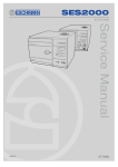
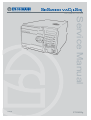
SES2000 VAC(LS3)
VACUUM AUTOCLAVE
Service Manual
110258
ST-SM45g
Read these Instructions before use
Introduction
Description
Maintenance
Illustrated
Parts list
Keep this ‘Service Manual’ in a safe convenient place for future reference. Read in
conjunction with the Publication detailed in Part 1.
This Service Manual applies to the following Autoclaves:Note: The ‘E’ in the serial number below is the ‘modification state’ of the autoclave and is used
within this manual to identify availability of spare parts where some items on early models are
no longer available.
SES 2000 Vac (LS3) - Standard, from Serial Number SVE1A0000
without printer - REF 87-050-06
with printer REF 87-050-14
SES 2000 Vac (LS3) - Long, from Serial Number SLVE1A0000
without printer - REF 87-050-22
with printer REF 87-050-30
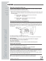
Eschmann After Sales Service Department
The Eschmann After Sales Service Department is staffed and equipped to provide advice and
assistance during normal office hours. To avoid delays when making enquiries, please quote the
Model and Serial Number of your Autoclave which is shown on the Serial Number plate, the
location of which is shown below. Please ensure you include all alpha and numeric digits of the
Serial Number.
Service manual
Serial Number
Plate
For further information visit www.eschmann.co.uk
All correspondence relating to the after sales service of Eschmann Equipment to be addressed to :
UK Customers
Eschmann Equipment, Peter Road, Lancing, West Sussex BN15 8TJ, England.
Tel: +44 (0) 1903 765040. Fax: +44 (0) 1903 875711.
Overseas Customers
Contact your local distributor. In case of doubt contact Eschmann Equipment.
Patents and Trade marks
The ESCHMANN logo is a registered trade mark of Eschmann Holdings Ltd.
“SES200” is a trade mark of Eschmann Holdings Ltd.
Patents : Patents Pending plus - Pat. US5090033 and Pat. GB2238407
Copyright © 2004 Eschmann Holdings Limited
All rights reserved. This booklet is protected by copyright. No part of it may be reproduced, stored in a
retrieval system or transmitted in any form or by any means, electronic, mechanical, photocopying,
recording or otherwise without written permission from Eschmann Holdings Limited.
The information in this publication was correct at the time of going to print. The Company, however,
reserves the right to modify or improve the equipment referred to.
The CE marking affixed to the product certifies that it complies with the
European Medical Devices Directive 93/42/EEC and related legislation.
ST-SM45g January 2005
SES 2000 Vac (LS3) AUTOCLAVE
CONTENTS
Page
Contents ..
Technical data
..
..
..
..
..
..
..
..
..
..
..
..
..
..
3
4
PART 1 INTRODUCTION
General
..
..
..
..
..
..
..
Associated publications
..
..
..
..
Servicing ..
..
..
..
..
..
..
..
..
..
6
6
6
PART 2 DESCRIPTION
General
..
..
..
..
..
..
Operating features ..
..
..
..
Operation cycle ..
..
..
..
..
Display messages
..
..
..
..
Error indication ..
..
..
..
..
General ..
..
..
..
..
..
Overheating ..
..
..
..
..
..
..
..
..
..
..
..
7
7
9
11
11
11
12
..
..
..
..
..
..
..
..
..
..
..
..
17
17
23
23
23
23
24
24
24
24
25
25
..
..
..
..
..
..
..
..
..
..
..
..
..
..
..
..
..
..
..
..
..
..
..
..
25
25
26
26
26
26
27
27
27
27
27
27
28
28
28
28
28
28
28
28
28
29
29
29
..
..
..
..
..
..
..
PART 3 MAINTENANCE
Fuses
..
..
..
..
..
..
..
Fault diagnosis ..
..
..
..
..
..
Parts replacement and adjustment ..
..
Autoclave cover ..
..
..
..
..
Reservoir assembly
..
..
..
..
Transformer ..
..
..
..
..
..
Control board
..
..
..
..
..
Pressure door lock
..
..
..
..
Steam bleed solenoid valve ..
..
..
Door interlock microswitch ..
..
..
Solenoid door lock..
..
..
..
..
Temperature sensors ..
..
..
..
Solenoid valves
Vacuum, steam bleed, water discharge
Air-Inlet Solenoid Valve Assembly
..
Water-Fill Solenoid Valve Assembly ..
Heating element ..
..
..
..
..
Door seal
..
..
..
..
..
..
Vacuum pump
..
..
..
..
..
Condenser ..
..
..
..
..
..
Cooling Fans ..
..
..
..
..
..
Bacterial air filter ..
..
..
..
..
Discharge line filter
..
..
..
..
Pressure transducer
..
..
..
..
Solid-state relay board ..
..
..
..
EMC board ..
..
..
..
..
..
Printer ..
..
..
..
..
..
..
Safety Valve ..
..
..
..
..
..
Band heater Temp. Sensor ..
..
..
Power switch
..
..
..
..
..
Float switch ..
..
..
..
..
..
Cooling ducts
..
..
..
..
..
Band heater ..
..
..
..
..
..
Chamber water level sensor ..
..
..
Manual reset cut-out ..
..
..
..
Reservoir water filter ..
..
..
..
Vacuum pump maintenance ..
..
..
ST-SM45g
Page
Display board ..
..
..
..
..
..
Special operating modes ..
..
..
..
Engineering mode ..
..
..
..
..
Machine Set-up mode ..
..
..
..
Set-up procedure ..
..
..
..
..
Setting the autoclave serial number
Setting the cycles in use..
..
..
Setting the display language ..
..
Setting date and time ..
..
..
Setting cycle counter
..
..
..
Errors and error clearing ..
..
..
..
Leak test procedure ..
..
..
..
..
Autoclave Calibration ..
..
..
..
..
General ..
..
..
..
..
..
..
Calibration procedure ..
..
..
..
Pressure relief valve test
..
..
..
Band heater calibration ..
..
..
..
Functional test
..
..
..
..
..
..
..
..
..
..
..
..
..
..
..
..
..
..
..
..
..
..
..
30
30
30
30
30
31
32
32
32
32
32
33
33
33
33
35
36
36
PART 4 ILLUSTRATED PARTS LISTS
Illustrated parts list 1: General spares
..
..
Illustrated parts list 2: Pipes and valves
..
..
Illustrated parts list 3: Heater
and process controls
..
..
..
41
44
46
ILLUSTRATIONS
Fig.1 SES 2000 Vac (LS3) autoclave ..
..
Fig.2.1a Autoclave door handle ..
..
..
Fig.2.1b Autoclave control panel..
..
..
Fig.2.2 Autoclave: general arrangement ..
Fig.2.3 Autoclave: pipes and valves ..
..
Fig.2.4 Autoclave: heater and process controls
Fig.2.5 Sterilizing system schematic diagram
Fig.3.1 Door interlock microswitch
..
..
Fig.3.2 Discharge line filter ..
..
..
..
Fig.3.3 Control panel and switch identities ..
Fig.3.4 Control board adjustments
..
..
Fig.3.5 System circuit diagram ..
..
..
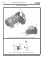
Fig.3.6 Piston vacuum pump
..
..
..
Fig.3.7 Replacement kit for piston pump ..
..
..
..
..
..
..
..
..
..
..
..
..
..
..
6
10
10
13
14
15
16
37
37
37
37
38
40
40
TABLE
Error code table ..
..
..
..
Fault Diagnosis table ..
..
..
..
..
..
..
..
..
12
17
APPENDIX A
Autoclave printer
..
..
..
Fig.A1-Fig.A4 Autoclave printer ..
..
..
..
..
..
..
50
51
APPENDIX B
PCA 424138 and Relay Assembly 112507
modification November 2004
..
..
..
..
52
APPENDIX C
New fittings for EMC board
..
..
53
..
..
Page 3 of 53
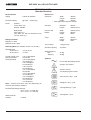
SES 2000 Vac (LS3) AUTOCLAVE
TECHNICAL DATA
(Standard Version)
Electrical Data
Dimensions
Supply
230Vac at 50/60Hz
Nominal Loading
@ 230V - 2kW (8.7A)
Fuses
Chassis
F10A, 250V, (x2)
Part No. 380003
Relay board
F5A, 250V (x1)
T2A, 250V (x1, was x 2 see Parts List 3)
T3.15A, 250V (x1)
Autoclave
Width
460mm
Length
650mm*
Height
360mm
* Feet spaced to fit 600mm worktop
Chamber
Diameter
Length
200mm
348mm (max)
Porous Load
basket
Width
Length
Height
156mm (max)
280mm
93mm
Trays
Width
Length
Height
183mm
282.6mm
l7mm
Tray Loading
1.5 kg per tray
Chamber capacity
10.6 litres
Weight (approx.)
Net
Shipping
45.7kg
50.0kg
Safety standards
EN61010-1:1993
EN61010-2-041:1996
Sterilizing Data (for software version 4.xx or later)
Sterilizing time
At 134/137°C
At 121/124°C
3 mins 15 sec.
15 mins
Typical overall cycle
time (D indicates
drying included)
134°C Unwrapped:
20 minutes
134°C Unwrapped:
35 minutes (D)
134°C Wrapped:
53 minutes (D)
134°C Porous:
63 minutes (D)
121°C Unwrapped:
28 minutes
121°C Unwrapped:
42 minutes (D)
121°C Wrapped:
62 minutes (D)
121°C Porous:
70 minutes (D)
Note: Overall cycle times may vary depending on
machine and loading conditions.
Nominal Operating pressures:
134°C cycle - 3.14 bar abs
121°C cycle - 2.11 bar abs
Water reservoir
capacity
Page 4 of 53
Symbols
For use with alternating current
Caution Hot Surface
Caution refer to
accompanying documents
"Porous load + Dry" cycle
"Wrapped + Dry" cycle
"Unwrapped+Dry" cycle
"Unwrapped" cycle
3.5 litres
ST-SM45g
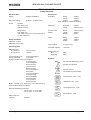
SES 2000 Vac (LS3) AUTOCLAVE
TECHNICAL DATA
(Long Version)
Electrical Data
Dimensions
Supply
230Vac at 50/60Hz
Nominal Loading
@ 230V - 2.75kW (12A)
Fuses
Chassis
15A, 250V, (x2)
Part No. 301871
Relay board
F5A, 250V (x1)
T2A, 250V (x1, was x 2 see Parts List 3)
T3.15A, 250V (x1)
Autoclave
Width
460mm
Length
650mm*
Height
360mm
* Feet spaced to fit 600mm worktop
Chamber
Diameter
Length
200mm
500mm (max)
Porous Load
basket
Width
Length
Height
156mm (max)
450mm
80mm
Trays
Width
Length
Height
180mm
450mm
23mm
Tray Loading
3.5 kg per tray
Chamber capacity
15.6 litres
Weight (approx.)
Net
Shipping
52kg
58kg
Safety standards
EN61010-1:1993
EN61010-2-041:1996
Sterilizing Data
Sterilizing time
At 134/137°C
At 121/124°C
3 mins 15 sec.
15 mins
Typical overall cycle
134°C Unwrapped:
time (D indicates
15 minutes
drying included) 134°C Unwrapped:
31 minutes (D)
134°C Wrapped:
46 minutes (D)
134°C Porous:
56 minutes (D)
121°C Unwrapped:
26 minutes
121°C Unwrapped:
41 minutes (D)
121°C Wrapped:
57 minutes (D)
121°C Porous:
67 minutes (D)
Note: Overall cycle times may vary depending on
machine and loading conditions.
Nominal Operating pressures:
134°C cycle - 3.14 bar abs
121°C cycle - 2.11 bar abs
Symbols
For use with alternating current
Caution Hot Surface
Caution refer to
accompanying documents
"Porous load + Dry" cycle
"Wrapped + Dry" cycle
"Unwrapped+Dry" cycle
"Unwrapped" cycle
Water reservoir
capacity
ST-SM45g
3.5 litres
Page 5 of 53
Part 1
SES 2000 Vac (LS3) AUTOCLAVE
PART 1 INTRODUCTION
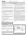
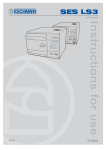
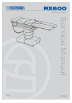
GENERAL (Fig. 1)
1
This Manual contains descriptive, maintenance
and spare parts information for the SES 2000 Vac (LS3)
autoclave units only.
Note: When sterilizing lubricated dental handpieces,
the reservoir water should be changed every week to
prevent contamination of the door seal, and other rubber
components, used in the pressure system.
2
The autoclave is a portable, electrically operated
steam unit designed for sterilizing wrapped, unwrapped
or porous loads. A drying phase is included in the porous
and wrapped cycles, which is optional for an unwrapped
cycle.
9
Eschmann recommend filling the reservoir with
‘Sterile Water for Irrigation’. This is low in dissolved solids
and has a low microbial count. In the U.K. the Department
of Health recommend that ‘Sterile Water for Irrigation’ is
used in bench-top Autoclaves (NHS Estates document
HTM2031).
3
Wrapped loads must be packed single-wrapped
in L.M.G. SMITH BROTHERS “VIEW-PACK SELF
SEAL” pouches, and sterilized using the special pouch
rack accessory. The autoclave will also take cassettes
using a cassette carrier. A wire basket is provided for
sterilizing porous loads.
If ‘Sterile Water for Irrigation’ is not being used then
Eschmann strongly recommend the use of either distilled
water, deionized water, purified water or water treated
by the reverse osmosis process. These types of water
are low in dissolved solids and can help reduce the
effects of tap water detailed below.
4
The autoclave operates automatically at the touch
of a single programme selector touch button, and has
eight sterilization programmes.
5
The autoclave is available with short or long
chambers and with or without an integral printer for
recording details of the sterilizing cycle. Details of the
printer are given in Appendix A page 50.
ASSOCIATED PUBLICATIONS
6
Separate installation and user instructions are
given in the SES 2000 Vac (LS3) autoclave ‘Instructions
for Use’, ST-IM62.
SERVICING
DO NOT USE TAP WATER, this is high in dissolved
solids and can deposit lime scale, block filters and cause
damage to the pressure vessel.
Eschmann also recommend that the reservoir is drained,
allowed to dry and is refilled on a weekly basis, with the
type of water detailed in ‘a’ (or ‘b’) above. At every service
interval the reservoir must be removed, be thoroughly
cleaned and dried, and then refilled. This will reduce
the build-up of contaminants in the water that may cause
blocked filters and/or damage to the pressure vessel.
Your local Health Authority may suggest that you change
the reservoir water more frequently. Eschmann advise
you to follow your local Health Authority’s
recommendations (also see PART 3, MAINTENANCE
para. 5 to 7).
WARNING
When replacing parts during maintenance
procedures ONLY use parts supplied by
Eschmann Equipment or the safety of the
autoclave may be affected.
7
Ensure that routine servicing is carried out at
regular intervals by either Eschmann trained personnel
or suitably trained engineers only, otherwise the warranty
could be infringed.
8
Keep the Instructions for Use and this Service
Manual readily accessible for reference purposes prior
to and during operation, cleaning and servicing of the
autoclave.
CAUTION
In common with other systems containing static
water reservoirs, water used in this unit can become
contaminated over a period of time, or following an
aborted cycle, and should be treated as a potential
risk of infection.
Page 6 of 53
Fig. 1 SES 2000 Vac (LS3) autoclave
ST-SM45g
SES 2000 Vac (LS3) AUTOCLAVE
Part 2
PART 2 DESCRIPTION
GENERAL (Fig. 1.1)
❑
1 The autoclave is a portable steam unit heated by
electric elements. For sterilization of porous loads, a
vacuum is created in the chamber. The unit is supplied
to suit the mains electrical supply shown in TECHNICAL
DATA (pages 4 and 5).
❑
2 The autoclave is electronically controlled and has
eight sterilizing programmes:
❑
134°C Porous load with drying
❑
134°C Wrapped load with drying
❑
134°C Unwrapped load with drying
❑
134°C Unwrapped load
❑
121°C Porous load with drying
❑
121°C Wrapped load with drying
❑
121°C Unwrapped load with drying
❑
121°C Unwrapped load
For typical sterilization cycle times, refer to TECHNICAL
DATA.
3 The required sterilizing programme is selected and
started by pressing the appropriate programme button on
the front panel of the unit, following which, the sterilizing/
drying cycle proceeds automatically until complete. The
printer (if fitted) will start automatically when the programme
button is pressed.
❑
❑
❑
❑
4 Indication of cycle status or error codes during a
cycle are provided by a digital display and printer (if fitted).
OPERATING FEATURES (Figs. 2.1, 2.2, 2.3 & 2.4)
5 The following equipment, designed for control or
protection, is incorporated in the autoclave:
❑
❑
❑
❑
Process Display Window (Fig. 2.2, item 1). The
digital display indicates the temperature and pressure
inside the chamber. It also provides simple messages
for the user which indicate the stages through the
cycle, and also error conditions, should any occur.
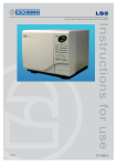
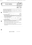
Four Programme Selector Buttons (Fig. 2.1b, SW1
to SW4). These are used to select and start
particular cycles. They can also be used to put the
autoclave in the ‘Engineering’ mode as described
later.
Green Light Emitting Diodes (LED’s) (Fig. 2.1b).
There are eight LED’s which flash primarily to
indicate the cycles available for selection that can
be started and, when this has been done, to indicate
the particular cycle which is in progress.
Power On/Off Switch (Fig. 2.1b). This switch
controls the mains power supply to the autoclave.
ST-SM45g
❑
❑
Overheat Warning Lamp (Fig. 2.1b). Illumination of
this lamp indicates that one of the two protective
overheat cut-outs has operated.
Door Latching Handle (Fig. 2.2, item 3). This handle
operates the door mechanism to secure the door in
the locked position against the chamber face.
Door Safety Latch (Fig. 2.2, item 5). Engages a
safety catch to ensure that the door does not fly
open should there be residual pressure in the chamber
when the door latching handle is operated. It can
also be used to keep the door slightly ajar when the
autoclave is not in use.
Door Interlock Microswitch (Fig. 2.4, item 4). This
is used to signal the controller that the door is
properly closed. It is operated by a simple, adjustable
mechanism and should operate just as the door is
fully closed.
Pressure Door Lock (Fig. 2.3, item 14). This is a
safety device designed to ensure that the door
cannot be opened if the internal chamber pressure
exceeds approximately 0.2 bar (3.0 lbf/in2). The
device comprises a spring-loaded plunger driven by
the chamber pressure via a rubber diaphragm.
Chamber Pressure Safety Indicator (Fig. 2.1a).
Fitted adjacent to the door latching handle (Fig.2.2
item 3) and operated by the pressure door lock
(Fig.2.3 item 14), it indicates that the chamber is
pressurised (red) and it is unsafe to open the door,
or unpressurised (green) and it is safe to open the
door.
Solenoid Door Lock (Fig. 2.4, item 12). The
solenoid door lock prevents the door being opened
by the operator once the cycle has started. The lock
holds the door closed until the sterilizing cycle is
complete. It will also keep the door closed under all
fault conditions. As absence of power is also a
‘fault’ the unit power switch must be set to ‘on’ in
order to open the door.
Note: It is necessary to override the electrical door
lock to clear an error code. This is done by setting
the power switch to ‘off’, then, after a few seconds,
setting it back to ‘on’ again while pressing and
holding the ‘P’ selector (SW5) on the front panel (Fig
2.1b).
Water Reservoir (Fig. 2.2, item 16). This is used to
hold distilled or deionized water or water treated by
reverse osmosis which is admitted into the chamber
via the water fill valve. The water reservoir also
receives hot water and steam vapour discharged
from the chamber towards the end of the cycle, via
the discharge valve. The vacuum pump (Fig. 2.3,
item 7) also discharges into the water reservoir.
Page 7 of 53
Part 2
SES 2000 Vac (LS3) AUTOCLAVE
PART 2 DESCRIPTION
❑
❑
❑
❑
❑
❑
Water Filter. The water filter is fitted on the end of
the water fill pipe in the water reservoir, and filters
the water entering the chamber.
Reservoir Float Switch (Fig. 2.3, item 11). The water
reservoir is fitted with a float switch which will stop
the cycle being started if there is insufficient water
in the reservoir to complete a chamber fill. ‘Fill
Reservoir’ will be displayed should this occur.
Heating Element (Fig. 2.4, item 1). The heating
element consists of a single immersion element
inside the chamber. The heating element is controlled
by a solid state relay and protected from overheating
by a manual reset thermostat. Refer to TECHNICAL
DATA for heater element loading.
Solid-State Relay Board (Fig. 2.4, item 14). See
Appendix B. There are a number of key functions
provided by the relay board:
w Solid state relays (SSR) control the mains
supply to the water heater element (10A), band
heater (10A) and vacuum pump (2A).
w SSR status LEDs, give an indication of drive
status (On/Off).
w Mechanical relay provides additional safety
for heater and pump circuits.
w Fuses for protecting the 20V a.c. supply (3.15A),
condenser fan (2A) and vacuum pump (5A)
see 'Parts List 3'.
w Two voltage regulators.
w Autoclave bleeper.
w Connections for mains loom, signal loom,
temperature and pressure sensors, solenoid
valves, and transformer.
w Interface for front panel, control board, and
printer.
Manual Reset Overheat Cutout (Fig. 2.4, item 21).
The manual reset overheat cutout is fitted at the rear
of the unit and is connected in series with the power
supply switch, band heater overheat cutout,
mechanical and SS relay and heater element. The
manual reset overheat cutout is operated by a fluidfilled capsule clamped to the heating element,
providing protection if the temperature of the heater
surface exceeds 250°C. It will remake electrically if
the reset button at the rear of the cabinet is pressed,
after giving the heater element time to cool.
Band Heater Overheat Cutout (Fig. 2.4, item 24).
The band heater cutout is fitted on the band heater
and is connected in series with the power supply
switch, Manual Reset Overheat Cutout, mechanical
and SS relay and Band Heater. It contains a bimetallic disc thermostat which operates if the
Page 8 of 53
❑
❑
❑
❑
❑
❑
❑
❑
❑
❑
temperature of the heater surface exceeds 250°C.
The cutout will remake electrically if the reset button
is pressed when the heater has cooled.
Fuses. The unit has five fuses:
w Two fuses (Fig. 2.4, item 2) on the rear panel
of the cabinet rated as shown in TECHNICAL
DATA, which are connected in the ‘mains
supply’ to the unit.
w Three more fuses are fitted on the solid-state
relay board (see TECHNICAL DATA).
Transformer (Fig. 2.4, item 17). The transformer
converts the incoming mains voltage to 24V a.c. It
is rated at 50VA.
Water Fill Solenoid Valve (Fig. 2.3, item 4). The
water fill valve controls the water fill sequence. It is
electrically operated from the 24V d.c. supply
generated and signalled from the SSR board.
Water Discharge Solenoid Valve (Fig. 2.3, item 3).
The water discharge valve is used at the end of the
sterilizing cycle to allow water and steam vapour
from the chamber to pass back into the reservoir.
The valve is electrically operated from a 24V d.c.
supply generated and signalled from the SSR board.
Discharge Line Filter (Fig. 2.3, item 12). Prevents
debris from the chamber entering and fouling the
water discharge valve.
Steam Bleed Solenoid Valve (Fig. 2.3, item 2). The
steam bleed solenoid valve operates in conjunction
with the steam bleed valve.
Steam Bleed Valve (Fig. 2.3, item 15). The steam
bleed valve is connected in series with the steam
bleed solenoid valve to bleed steam from the chamber
during the 121°C cycles. It contains a ball and
spring which allows air displaced by the steam
generated in the chamber to pass into the reservoir.
Once steam starts to pass, the ball then lifts and
seals. A small ‘bleed’ remains, however, and it is
quite normal for small quantities of steam to escape
into the reservoir throughout the cycle.
Safety Valve (Fig. 2.3, item 16). The safety valve
is fitted on the chamber tee-piece at the rear of the
chamber, and is factory set to release pressure from
within the chamber. It is a primary safety device and
must not be readjusted.
Air In Solenoid Valve (Fig. 2.3, item 5). The air inlet
valve controls the admission of bacteriologically
filtered air to the chamber during the drying phase.
A non-return valve prevents flow from the chamber
to the bacterial filter to keep it dry.
Vacuum Solenoid Valve (Fig. 2.3, item 1). When
open, this valve allows the vacuum pump to suck air
and steam from the chamber.
ST-SM45g
SES 2000 Vac (LS3) AUTOCLAVE
Part 2
PART 2 DESCRIPTION
❑
❑
❑
❑
❑
❑
❑
❑
❑
Vacuum Pump (Fig. 2.3, item 7). The vacuum pump
is a two stage diaphragm pump used to suck air and
steam from the chamber. Some models were fitted
with a piston pump (see Fig. 3.6) which is no longer
available, in case of fault, replace it with the current
diaphragm pump.
Condenser (Fig. 2.3, item 6). The condenser precools air and steam from the chamber before it
enters the vacuum pump.
Bacterial Filter (Fig. 2.3, item 10). The bacterial filter
filters the air entering the chamber.
Chamber Temperature Sensors (Fig. 2.4, item 16).
These are used to sense the chamber temperature
and are fitted at the rear of the chamber. One sensor
controls the temperature within the chamber and the
other controls the displayed and the printed
temperatures.
Band Heater Temperature Sensor (Fig. 2.4, item
15). The band heater temperature sensor is used to
control the band temperature during the drying
phase.
Thermocouple Entry Port (Fig. 2.4, item 23). This is
used to insert a thermocouple into the chamber to
allow the operating temperature to be measured
and, if necessary, adjusted.
Pressure Test Port (Fig. 2.4, item 22). The pressure
test port is used to insert a pressure measuring
probe to monitor the chamber pressure.
Control Board (Fig. 2.4, item 19). The control board
interfaces with the relay board and front panel board
to control every aspect of management of the
autoclave. The main features are:
w Two microcontrollers (U1 and U12 Idents. on PCB)
which receive information from the front panel and
all the sensors (temperature (3 off), pressure, door
interlock, chamber water level, reservoir level). If
any errors are detected they are shown on the
display, and printed (if a printer is fitted) as error
codes (see Part 2, para. 28 and 29).
w Message memory (U13) in four variants
covering all the main languages spoken by
Eschmann customers.
w Trimmer potentiometers for calibration of the
band heater and temperature/pressure
channels.
w Engineering switch for set-up and calibration
modes (see special operating modes page 30).
w Outputs from the control board control the
heaters, pump, and solenoid valves via the
relay board interface.
Front Panel Board (Fig. 2.4, item 13). This board
incorporates the vacuum fluorescent display,
ST-SM45g
❑
❑
❑
❑
❑
programme select and cancel switches, and
programme indicator LEDs. It interfaces with the
control and relay boards via a 10-way ribbon
connector.
Pressure Transducer (Fig. 2.4, item 7). The pressure
transducer monitors the pressure in the chamber
and generates chamber pressure signals for cycle
monitoring, control, and display.
Printer (Fig. 2.2, item 21). The printer, if fitted, starts
automatically when a cycle button is selected and
will print out a hardcopy of the sterilization cycle.
Details of the printer are given in Appendix A to this
Manual.
Fans (Fig. 2.4, items 10 and 11). Two fans are fitted
in the autoclave. One fan provides cooling for the
condenser and the PCB compartment (via a bleed
conduit). The other fan draws air over the chamber
for rapid cooling between cycles.
Band Heater (Fig. 2.4, item 18). The band heater
heats the chamber during the drying cycle.
EMC Board (Fig. 2.4, item 5). The EMC board
provides electro-magnetic compatibility protection
for the autoclave.
OPERATION CYCLE
6 A detailed knowledge of the operation of the autoclave
is not necessary to be able to repair it effectively;
however, a basic understanding of the various processes
of autoclave operation which occur during a cycle is given
in the following paragraphs.
CAUTION
Ensure that the Autoclave is switched off before
filling the reservoir. DO NOT USE TAP WATER.
Note: When filling the reservoir, consult the 'Instructions
for Use' which provides information on the types of water
that should be used.
7 Power is switched on by selecting the power switch
(O-I) to I (Fig. 2.1b). If the chamber door is open there now
follows a single audible tone accompanied by the display
'SES Vacuum LS3+cycle count+version of software',
which then changes to 'CLOSE THE DOOR'.
8 If the door is closed, when power is switched on, the
display will show 'SES Vacuum LS3+cycle count+version
of software', which then changes to 'OPEN THE DOOR'.
9 After the work trays have been put in the chamber
and the door closed, a programme can be selected and
initiated by pressing one of the programme selector
buttons (Fig. 2.1b). If the autoclave has a printer it will
automatically start when the programme selector button
is pressed.
Page 9 of 53
Part 2
SES 2000 Vac (LS3) AUTOCLAVE
PART 2 DESCRIPTION
10 When the door is closed, with the power switched on,
this is sensed by the control board via the door interlock
switch. If any attempt is made to open the door once the
cycle has begun, the display 'ERROR 2' will appear and
an audible signal will sound. Under these circumstances
it is necessary to switch the autoclave off, wait 5 seconds,
reset the error (see Part 3, para. 54) and restart the cycle.
11 The autoclave operates automatically at the touch of
a single programme selector touch button ( Fig. 2.1b), and
has eight programmes:
❑
134°C Porous load with drying (SW1)
❑
134°C Wrapped load with drying (SW2)
❑
134°C Unwrapped load with drying (SW3)
❑
134°C Unwrapped load (SW4)
❑
121°C Porous load with drying (SW1)
❑
121°C Wrapped load with drying (SW2)
❑
121°C Unwrapped load with drying (SW3)
❑
121°C Unwrapped load (SW4)
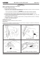
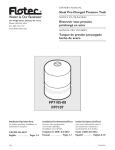
12 Each programme selector button on the control panel
(Fig. 2.1b) will select either the 134°C or 121°C cycles.
The programme indicator lights, at each side of the
programme selector buttons, will change to indicate a
change of selection between 134°C and 121°C each time
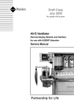
Locked
Door lock position
indicator
Safety catch
behind door plate
Unlocked
Chamber pressure
indicator
Fig. 2.1a Autoclave door handle
the appropriate selector button is pressed. In addition,
the display will show the appropriate programme
description to confirm the programme that has been
selected. Once the programme and the temperature
range has been selected, the sterilization cycle will start
automatically, after a delay of approximately four seconds.
13 The printer, if fitted, will start printing and, as the
cycle progresses, various display messages will appear
in the display window to indicate the programme status.
Note: If a programme is started in error, it can be cancelled
by pressing the 'P' selector button (SW5), provided that the
cycle has not reached the water fill stage.
14 When a cycle is selected (SW1- SW4 pressed),
'CYCLE STARTED' will be displayed, quickly followed by
'VACUUM ON', indicating that the vacuum pump has
started, and the vacuum solenoid valve has opened to
evacuate the air from the chamber.
15 When the pressure in the chamber has decreased to
the required value for the programme selected, the water
fill valve will open and 'FILLING' will be displayed, indicating
that water is being sucked from the reservoir and into the
chamber.
16 When the cycle has started, the door cannot be
opened due to the electric door lock and vacuum force on
the door.
17 When the correct quantity of water has entered the
chamber, the water fill valve closes together with the
vacuum valve. The heater, controlled by the control
board, will switch on, and the pressure in the chamber will
increase. This phase is indicated by 'PULSING' being
shown on the display.
18 The heater is controlled by a system which ensures
that the operating temperature is reached with minimal
overshoot. Initially, the heater will be 'on' continuously
and the measured temperature will be displayed. Note,
however, that the system does not register temperatures
below 92°C.
19 Temperatures are displayed with a resolution of
0.1°C, using signal averaging to ensure a stable, accurate
display.
Fig. 2.1b Autoclave control panel
Page 10 of 53
20 Control of the cycle is fully automatic with temperature
information being monitored by temperature sensors.
Timing is controlled by the control board and cycle times
cannot be adjusted. By comparing measured values with
known time/temperature relationships, the control board
is able to detect faults such as lack of water at the fill
stage, or loss of water and steam during the process, and
ST-SM45g
SES 2000 Vac (LS3) AUTOCLAVE
Part 2
PART 2 DESCRIPTION
it will indicate such problems by displaying errors codes
such as 'ERROR 3' or 'ERROR 4' respectively, which will
be accompanied by an audible warning signal (see Error
Code Table page 12).
DISPLAY MESSAGES
27 Throughout a selected cycle the following symbols
may appear on the digital display:
Display
21 The autoclave operates at temperatures slightly
above the usual recommended minimums. The operating
temperature for the 121°C cycle is set to 122°C, and the
134°C cycle is set for 135°C.
Meaning
OPEN THE DOOR
Door was closed when the
autoclave was switched 'on'.
PLEASE WAIT*
The autoclave is measuring
atmospheric pressure
CLOSE THE DOOR
The door is open and the cycle
cannot start.
READY FOR USE
Waiting programme selection.
CYCLE STARTED
Programme selected and cycle
started.
23 Once the controller detects that chamber temperature
and pressure have fallen to a safe level, the display
'CYCLE COMPLETE' will be shown to indicate that the
cycle is complete. When the chamber door is opened the
display will show 'CLOSE THE DOOR'.
VACUUM ON
Chamber air/steam discharge
in progress.
FILLING
Water entering chamberprior to
steriliszation
Note: If the autoclave has a printer, the printout will
include the following details:
PULSING
Pre-sterilization
treatment.
❑
❑
❑
❑
❑
❑
STERILIZING
Sterilization in progress.
CONDENSING
Discharging water and steam
from chamber.
DRYING
Load being dried (time remaining
to the end of cycle will also be
shown).
CYCLE COMPLETE
Cycle completed successfully.
22 As the cycle enters the sterilization phase, the
display shows 'STERILIZING'. At the end of the sterilizing
phase the heater is turned off and the discharge valve is
opened to discharge water and steam from the chamber.
This phase is indicated by 'CONDENSING' being shown
on the display.
Autoclave type and serial number.
Date and time of sterilization cycle.
Counter indication (five digits with leading zeros).
Sterilization cycle type, e.g. 134°C without drying.
Sterilization cycle time, temperature, and pressure.
Sterilization cycle ended message.
Operating information relating to the printer is given in
Appendix A to this Manual.
24 The overall time for the cycle is not fixed and
depends on many factors such as the supply voltage, the
load, and the ambient temperature. However, the control
board will ensure a satisfactory sterilization cycle even
when these factors vary over wide ranges.
25 If a cycle employing a drying phase is selected,
operation to the end of the sterilizing phase is as described
previously. After discharge of steam and water back into
the reservoir, however, the display 'DRYING' will be
indicated, together with the time remaining to the end of
the cycle. During the drying phase, operation of the
autoclave will alternate between vacuum pulses and
filtered air inlet pulses to achieve optimum drying.
26 The length of the drying phase will vary according to
the programme selected, and the chamber band heater
will operate to promote drying. At the end of the drying
phase, the display 'CYCLE COMPLETE' will appear
indicating that the door can be opened.
ST-SM45g
steam
* Only applicable to software version 5.2 or above (as
shown briefly on display when autoclave first switched on).
ERROR INDICATION
General
28 If an error occurs during the cycle, an error code will
be displayed (see the Error Code Table on page 12).
29 If an error occurs during a cycle, the control board will
cancel the cycle (see Fault Diagnosis, and Errors and
Error Clearing in Part 3).
Note: These error codes will generally require investigation
by an Eschmann trained engineer. If an error occurs
during the cycle, the printer (if fitted) will print out the date
and time, the message 'CYCLE FAILED' and the appropriate
error code. Information relating to the printer, if fitted, is
given in Appendix A to this Manual.
Page 11 of 53
Part 2
SES 2000 Vac (LS3) AUTOCLAVE
PART 2 DESCRIPTION
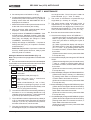
ERROR CODE TABLE
Display
Overheating
Meaning / Cause
POWER FAILURE
(Error 1 not shown)
Temporary failure in the
mains supply to the unit.
Error 2
Faulty or incorrectly adjusted
door switch, or door not fully
closed at start of cycle.
Error 3
Water failed to enter chamber
from reservoir.
Error 4
Water level in chamber has
dropped during run-up to
sterilizing cycle.
Error 5
Heater element not working
during run-up to sterilizing phase.
Error 6
Control channel low temperature.
Error 7
Control
channel
temperature.
high
Error 8
Display
channel
temperature.
low
Error 9
Display
channel
temperature.
high
Error 10
Insufficient first vacuum pulse.
Error 11
Insufficient second vacuum
pulse.
Error 12
No steam pulse.
Error 13
(i) Before filling takes place
= Air Detector test failure
30 In the unlikely event of overheating, the red overheat
warning lamp (see Fig. 2.1b and Fig. 2.4 item 8 ) at the
front of the autoclave will illuminate. If this happens, first
allow 10 to 15 minutes to elapse for the autoclave to cool,
then check the water level in the reservoir and top-up if
required. When the water level is correct, press the
'PRESS TO RESET' button at the rear of the cabinet (Fig.
2.4 item 21) and restart the cycle as normal. If the fault
persists, switch off the autoclave and call an Eschmann
Trained Engineer.
(ii) At beginning of sterilization =
Steam quality error.
Error 14
Insufficient drying vacuum.
Error 15
Sensor system failure.
Error 16
Clock speed error during
sterilizing phase.
Error 17
Band heater not achieving
setpoint temperature during
drying phase.
FILL RESERVOIR
Water level in reservoir has
dropped below 'MIN' mark.
Page 12 of 53
ST-SM45g
SES 2000 Vac (LS3) AUTOCLAVE
Part 2
PART 2 DESCRIPTION
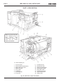
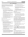
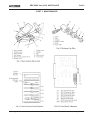
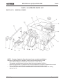
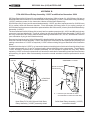
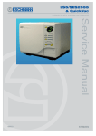
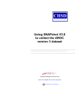
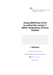
Note: Some autoclaves will have a
different pump to that shown. See
maintenance section and parts list for
pump replacement details.
1
2
3
4
5
6
7
8
9
Process display window
Control panel
Door latching handle
Pressure door
Door latch
Pressure safety indicator
Door cover
Seal retaining disc
Door seal
10
11
12
13
14
15
16
17
18
Seal retaining rim
Aerotight nut
Door safety catch
Pressure chamber assembly
Work tray
Reservoir lid
Reservoir
Cover screw
Unit cover
19
20
21
22
23
24
25
26
Front panel
Chassis
Printer
Foot
Door beam
Door knob
PCB cooling conduit
Link
Fig. 2.2 Autoclave: General Arrangement
ST-SM45g
Page 13 of 53
Part 2
SES 2000 Vac (LS3) AUTOCLAVE
PART 2 DESCRIPTION
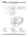
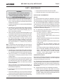
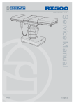
Note: Some autoclaves will
have a different pump to
that
shown.
See
maintenance section and
parts list for pump
replacement details.
'A' - Stud coupling nut
1
2
3
4
5
6
7
8
Vacuum valve
Steam bleed solenoid valve
Water discharge valve
Water fill valve
Air in valve
Condenser
Vacuum pump
Pump foot
9
10
11
12
13
14
15
16
Transducer coil
Bacterial air filter
Reservoir float switch
Discharge line filter
Non-return valve
Pressure door lock
Steam bleed valve
Safety valve
Fig. 2.3 Autoclave: Pipes and Valves
Page 14 of 53
ST-SM45g
SES 2000 Vac (LS3) AUTOCLAVE
Part 2
PART 2 DESCRIPTION
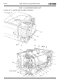
Note: Some autoclaves will have a
different pump to that shown. See
maintenance section and parts list for
pump replacement details.
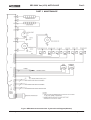
1
2
3
4
5
6
7
8
Heating element
Mains fuses
Mains cable
Microswitch
EMC board
Choke
Pressure transducer
Overheat warning lamp
9
10
11
12
13
14
15
16
ON/OFF (O/I) switch
Enclosure fan
Condenser fan
Solenoid door lock
Front panel board
Solid-state relay board*
Band heater temperature sensor
Chamber temperature sensors
17
18
19
20
21
22
23
24
25
Transformer
Band heater
Control board
Printer
Manual reset overheat cut-out
Pressure test port
Thermocouple entry port
Band heater overheat cut-out
Bulb (for Manual Reset 21)
* see Appendix B
Fig. 2.4 Autoclave: Heater and Process Controls
ST-SM45g
Page 15 of 53
Part 2
SES 2000 Vac (LS3) AUTOCLAVE
PART 2 DESCRIPTION
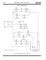
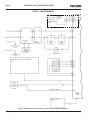
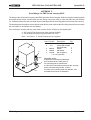
Fig. 2.5 Sterilizing System Schematic Diagram
Page 16 of 53
ST-SM45g
SES 2000 Vac (LS3) AUTOCLAVE
Part 3
PART 3 MAINTENANCE
FUSES (Fig. 2.4 )
1 The autoclave is protected by five fuses. Two mains supply fuses are fitted on the rear cover of the autoclave
(Fig. 2.4 item 2). Three more fuses are fitted to the solid state relay board (Fig. 2.4. item 14). All fuse ratings are given
in the TECHNICAL DATA section.
FAULT DIAGNOSIS
2 A number of typical faults which could occur, their possible causes and how to remedy them are listed below. For
maintenance procedures refer to Parts Replacement and Adjustment.
Note: Cross references in the ‘Remedy’ column (e.g. para.10) refer to paragraphs in the Parts Replacement and
Adjustment section that follow later in Part 3.
WARNINGS
Switch-off and disconnect mains power supply before removing the autoclave cover, or doing
maintenance procedures. During certain procedures mains voltage may have to be present with the
cover removed and extreme care should be taken to avoid contact with mains voltage.
Check that chamber is at atmospheric pressure before opening the door.
Should the door be opened beware of possible very hot water or steam escaping from the chamber.
Fault Diagnosis Table
Fault
(1) Nothing happens when power
switched on (No display).
Possible Cause
(a)
Mains supply failure.
(b)
Main fuses blown
(rear panel).
Faulty power switch.
(c)
(d)
(e)
Solid-state relay board
fuse blown or loose.
Transformer failed.
(f)
Short circuit on
24V circuit.
(g)
Short circuit on solid-state
relay board.
Remedy
(a) Check mains supply, also
plug and supply cable
for loose connections
or breaks.
(b) Replace fuse(s)*.
(c) Replace power switch
(para 31).
(d) Replace fuse*.
(e) Check transformer secondary
voltage (20V a.c. rms).
Replace transformer if
output is zero (para 8).
(f) Check sensor, fill valve, vent
valve etc. for short circuit
Replace where necessary.
(g) Check SSR board is correctly
fitted in bottom guide,
with correct clearance from
dividing panel. Also see
Appendix B
*Note: Blown fuses can indicate further problems. Always investigate the reason for any fuse blowing,
but bear in mind that fuses can ‘age’ and blow for no other reason.
Continued
ST-SM45g
Page 17 of 53
Part 3
SES 2000 Vac (LS3) AUTOCLAVE
PART 3 MAINTENANCE
Fault
(2)
Door cannot be opened.
Possible Cause
(a)
Pressure door lock jammed.
(b)
Pressure in chamber.
(c)
Vacuum in chamber.
(d)
Solenoid door lock
inoperative when autoclave
power is switched on.
Remedy
(a) Replace pressure door lock
(para.10). To open chamber
door, push pressure locking
bolt back with a thin blade
if spring faulty. If spring has
seized, disconnect body from
unit (para.10) and pull it
backwards so that the locking
bolt clears the door.
(b) Switch-on power to release
pressure in chamber.
(c) As (b) to open door then
check discharge filter and
bacteriological filter for
blockage.
(d) Check wiring to solenoid door
lock and check solenoid for
shorting or open circuit.
Replace solenoid door lock if
necessary (para.13).
(3)
Chamber will not fill
(FILL RESERVOIR displayed).
(a)
(b)
No water in reservoir.
Water in float switch.
(a) Fill reservoir.
(b) Fit new float switch (para.32).
(4)
Display shows ERROR 3.
(a)
No water in chamber due to
water fill valve or associated
pipes or filter blocked.
(b)
Sensor not detecting water
in chamber.
(a) Clean or fit new water filter
(para.37). Strip pipework
and clean. Empty and clean
reservoir. Refill with
distilled water (para.9 part 1).
(b) Ensure chamber water level
sensor is clear of obstructions
Also, ensure sensor is not
dirty or corroded.
(a)
Door interlock
microswitch jammed
in closed position.
Switch fault.
Door interlock
microswitch out
of adjustment.
(a) Check switch operating
lever for freedom of
movement.
(b) Check operation of switch.
(c) Adjust switch lever position,
or fit new microswitch if
adjustment is correct (para 12).
(a)
Door opened after
cycle selected.
(b)
Door switch out of
adjustment.
(a) Switch power off, wait
5 seconds, reset error (see
para (53) and restart cycle.
(b) Adjust switch lever position,
or fit new microswitch
(para 12).
(5)
Display still shows
‘OPEN THE DOOR’
after door is opened.
(b)
(c)
(6)
Display shows ‘ERROR 2’
after cycle started.
Continued
Page 18 of 53
ST-SM45g
SES 2000 Vac (LS3) AUTOCLAVE
Part 3
PART 3 MAINTENANCE
Fault
(7)
(8)
(9)
Safety valve leaks (See also
Fault (8)).
Safety valve operates even
though temp is below 136°C
(See also Fault (7)).
Temperature above 137°C
causing safety valve to
operate.
(10) ‘ERROR 4’ displayed
before sterilizing temp.
reached.
Possible Cause
(a)
Dirt on valve seat.
(b)
Check pressure and
temperature to see if
calibration is set too high.
(a)
(b)
Safety valve fault.
Re-calibration needed.
(c)
(d)
Chamber temperature
sensor fault.
Control board fault.
(a)
Failed solid state relay.
(a) Fit new solid state relay
board (para.26). Also see
Appendix B
(a)
Water fill valve leaking.
(b)
Discharge valve leaking.
(c)
Chamber water level
sensor fault.
Wiring loom fault.
Door seal leaking.
(a) Drain reservoir and fit new
water fill valve (para.17).
(b) Strip and clean water
discharge valve or fit a
new one (para.15).
(c) Fit new chamber water level
sensor (para.35)
(d) Check terminations.
(e) Clean mating surface of
gasket around door with a
soapy cloth. If leakage
persists, replace doorseal (para.19).
(d)
(e)
(11) ‘ERROR 5’ displayed.
Remedy
(a)
(b)
Solid state relay
failed (No voltage
across heater).
Heater open-circuit.
(c)
Control board fault.
(a) With low pressure in chamber
carefully operate valve
by hand (Warning: Beware
of risk of scalds from escaping steam). If leakage persists, fit new safety valve
(para .29).
(b) Re-calibrate control board
(para.57 onwards).
(a) Fit new safety valve (para.29).
(b) See Calibration Procedure
(para.57 onwards).
(c) Fit new temperature sensor
(para.14).
(d) Fit new control board
(para.9).
(a) Fit new relay board
(para.26). Also see
Appendix B
(b) Fit new heater if resistance
of element when cold is not
approx. 30ohms (short autoclave) or 20ohms (long autoclave) (para.18).
(c) Fit new control board
(para.9).
Continued
ST-SM45g
Page 19 of 53
Part 3
SES 2000 Vac (LS3) AUTOCLAVE
PART 3 MAINTENANCE
Fault
Possible Cause
Remedy
(12) Temperature differs from
measured value and display
shows ‘Err 6, 7, 8, or 9’.
(a)
Recalibration required.
(a) Recalibrate (para.57 onwards).
(b)
Chamber temperature
sensor fault.
(b) Check sensor fitted
correctly, or fit new
sensor (para.14) and
recalibrate (para.57 onwards).
(13) No discharge of steam/water
at end of cycle.
(a)
Discharge valve fault.
(b)
Wiring fault.
(c)
Blockage in discharge
line.
Control board fault.
(a) Test valve, using ‘Engineering
Mode’(para.40). Replace if
faulty (para.15).
(b) Check connections to
discharge valve.
(c) Strip pipework and clean.
(d)
(14) Cycle time much longer
than usual.
(15) Unusual display when
first switching on power.
(16) Display shows
‘POWER FAILURE’.
(e)
Discharge line
filter blocked.
(a)
(b)
Low mains voltage.
Autoclave overloaded.
(c)
(d)
Slow discharge at end
of cycle.
Faulty vacuum pump.
(e)
Leak in pressure system.
(a)
Control board failed to
re-set properly.
(b)
Control board fault.
(a)
Temporary mains
failure during cycle.
(d) Replace control board
(para.9).
(e) Clean or replace filter
(para.24).
(a) Check supply to autoclave.
(b) Avoid overloading (see Tray
loading in Technical Data
section)
(c) See Fault (13) (c) and (e).
(d) Repair or fit new vacuum
pump (para.20).
(e) Check and repair.
(a) Switch-off power, wait for
approx. 5 seconds and switch
on again.
(b) Fit new control board
(para.9).
(a) Check local supply conditions.
(b) Check supply plug wiring and
power cable for breaks.
(c) Carry out error cancellation
(para.53) then remove load
from chamber. Ensure load is
conditioned (dry) before
restarting appropriate cycle.
Continued
Page 20 of 53
ST-SM45g
SES 2000 Vac (LS3) AUTOCLAVE
Part 3
PART 3 MAINTENANCE
Fault
(17) Overheat warning lamp
illuminates.
(18) Pressure display reads
too high or too low.
(19) Door stiff to rotate/open.
(20) ERROR 10: Insufficient first
vacuum pulse.
Possible Cause
Remedy
(a)
Band heater overheat
thermostat operated.
(b)
Heater element overheat
thermostat operated.
(a)
Incorrect calibration.
(a) Check temperature/pressure
calibration (para.57 onwards).
(b)
Faulty electrical connection.
(b) Check sensor connections
and solid-state relay board
and control board connection.
(a)
Door mechanism requires
lubrication.
(b)
Door seal mating surfaces
sticking.
(c)
Chamber pressure slow to
stabilise at atmospheric
pressure.
(a) Lubricate hinge pivots with
silicone grease (Part
No.306055).
(b) Clean mating surfaces
of door seal and chamber
flange with a clean cloth.
(c) Check for blockages in
discharge line and/or
bacterial filter air inlet line.
(a)
Previous cycle has left chamber (a) Reset chamber condition by
too hot and wet.
running a 134°C unwrapped
with drying cycle and leave
door open for 5 minutes on
completion.
Pressure not less than 20kPa
(b) Carry out leak test (para.55)
on display due to pump
If it fails, check pump
inefficiency.
components for leaks, check
all connections, door seal, and
solenoid valves for leaks.
Pressure calibration error.
(c) Recalibrate pressure channel
(para.57 onwards).
Pump cooling duct not fitted.
(d) Fit cooling duct (para.33) and
(models up to mod state 'E' only)
check cooling fan operation .
(b)
(c)
(d)
(a) Faulty band heater
temperature sensor. Fit new
band heater temperature
sensor (para.30). Or, Solid
state relay faulty. Replace
solid state relay
board (para.26). Also see
Appendix B
(b) Faulty solid state relay.
Fit new solid state relay
board (para.26). Also see
Appendix B. Or, ensure
chamber water level sensor is
clear of obstructions. Also,
ensure sensor is not dirty or
corroded.
Continued
ST-SM45g
Page 21 of 53
Part 3
SES 2000 Vac (LS3) AUTOCLAVE
PART 3 MAINTENANCE
Fault
(21) ERROR 11: Insufficient
second vacuum pulse.
Possible Cause
(a)
(b)
(c)
(d)
Remedy
Previous cycle has left chamber (a) Reset chamber condition by
too hot and wet.
running a 134°C unwrapped
with drying cycle and leave
door open for 5 minutes on
completion.
Pressure not reducing to set
(b) Carry out leak test (para.55)
point due to pump
If it fails, check all
inefficiency.
connections, door seal, and
solenoid valves for leaks.
Pressure calibration error.
(c) Recalibrate pressure channel
(para.57 onwards).
Pump cooling duct not fitted.
(d) Fit cooling duct (para.32) and
check cooling fan operation.
(22) ERROR 12: No steam pulse.
(a)
Display Pressure not reaching
120kPa (Porous and wrapped
cycles) or 98kPa (unwrapped
cycles).
(23) ERROR 13: Steam quality
error, displayed at the
beginning of the
sterilizing phase.
(a)
At beginning of sterilizing phase, (a) Check chamber temperature
pressure displayed is not within
sensors are fitted correctly,
preset limits.
recalibrate pressure and
temperature (para.57 onwards).
Also see Appendix B
(24) ERROR 13: Air detector test
failed, displayed prior to
filling phase.
(a)
Two minute duration leak test
immediately prior to filling stage
has failed. Displayed pressure
has increased by 4kPa over a
two minute period.
(25) ERROR 14: Insufficient
drying vacuum (Display
pressure not reaching 50kPa).
(a)
Insufficient pump efficiency.
(b)
(a) Check heater element (i.e.not
open circuit), solid state relay
(RL2) energised (red LED,
D6 on SSRB Fig.2.4 item14)
and mains voltage is reaching
heater element. Also see
Appendix B
(a) Ensure load is correctly
conditioned (dry) before
starting cycle. Ensure autoclave passes a leak test
(para.55). Ensure chamber
has been ventilated with door
open for at least one minute
before starting cycle.
(a) Check pump function, repair
or replace (para.38 and 20)
if required and check all
connections for leaks.
Pump failed to start at begin(b) Check pump valve seats
ning of drying phase (stalled).
have leakage path.
(models up to mod state 'E' only)
(models up to mod state 'E' only)
(26) ERROR 15: Chamber
temperature sensor failure.
(a)
Temperature readings differ
by more than 5°C during
heat-up through 100°C.
(a) Check chamber temperature
sensors are clamped tightly
to chamber and re-calibrate
(para.57 onwards).
(27) ERROR 16: Clock speed
error during sterilizing phase.
(a)
Real-time clock has stopped.
(a) Re-start clock by resetting
time in SET-UP mode (para.
51). If this is not successful,
replace control board (para.9).
Continued
Page 22 of 53
ST-SM45g
SES 2000 Vac (LS3) AUTOCLAVE
Part 3
PART 3 MAINTENANCE
Fault
(28) ERROR 17:
Insufficient drying.
Possible Cause
Band heater not reaching setpoint
temperature due to:
(a) Calibration error.
(b) Band heater sensor faulty.
(c) Control board faulty.
(d) Faulty solid state relay or
connections.
(e) Faulty band heater.
PARTS REPLACEMENT AND ADJUSTMENT
WARNING
Switch-off and disconnect mains power supply
before removing autoclave cover, or doing
maintenance procedures.
Removal
5
b Pull off silicone tubing from manifold connection.
c Disconnect discharge and fill tubes from the manifold,
ensuring that the manifold fittings do not rotate
whilst releasing the compression nuts.
d Disconnect reservoir float sensor electrical
connections.
Autoclave Cover (Fig. 2.2, item 18)
e Withdraw reservoir and manifold from autoclave,
whilst guiding the drain tube up through the chassis
floor and dividing panel.
Removal
CAUTION
An earth lead is connected between the terminal
block and the earth stud inside the rear of the cover.
Disconnect the lead before removing the cover
completely.
a Unscrew and remove the four cover screws (two on
each side) from the casing lower edge.
b Remove reservoir lid.
c With unit facing towards you, remove the cover
lifting it from the rear of the unit first.
Refitting
4
To refit the cover:
a Re-connect the earth lead between the terminal
block and the earth stud inside the rear panel of the
cover.
b Carefully locate the tabs at the front of the cover into
the slots in the top of the front panel of the unit, then
press the cover down in position.
c Refit the four cover screws and the reservoir lid.
ST-SM45g
Remove reservoir assembly as follows:
a Remove reservoir cover.
When the door is opened beware of possible
very hot water or steam escaping from the
chamber.
To remove the cover:
(a) Check calibration (para.57
onwards ).
(b) Fit new sensor (para.30).
(c) Fit new control board (para.9).
(d) Fit new SSR board if connections satisfactory (para.26).
Also see Appendix B
(e) Fit new band heater (para.34).
Reservoir Assembly (Fig. 2.2, Item 16)
Check that chamber is at atmospheric pressure
before opening the door.
3
Remedy
Cleaning
6
Clean reservoir and manifold as follows:
a Separate the manifold and reservoir.
b Wash the manifold and reservoir in a weak solution
of detergent and tap water.
c Rinse all cleaned components thoroughly with tap
water to remove any residual detergent. Allow
components to dry.
d Clean or replace water filter.
Assembly
7 Assemble and refit reservoir assembly and fill with
distilled water.
Note: If fitting the drain tube to the reservoir connection,
dip the end of the tube in warm water first to soften it.
Transformer (Fig. 2.4, item 17)
8 Detach the transformer connections, noting the
position of each one. Remove cable-tie and two nylon
thumb nuts then withdraw transformer. The replacement
transformer should be an identical unit, rated at 50VA. To
fit replacement transformer, reverse the removal procedure.
Page 23 of 53
Part 3
SES 2000 Vac (LS3) AUTOCLAVE
PART 3 MAINTENANCE
Control Board (Fig. 2.4, item 19)
9 To remove control board, pull on handle provided and
slide control board on tracks. Replacement is the reverse
of the removal procedure, but ensure that board locates
firmly in the solid state relay board.
Note 1: When a new control board is fitted, it will be
necessary to recalibrate it to suit the temperature sensor
fitted in the machine (see Calibration Procedure, para. 57
onwards).
Note 2: When ordering a new control board (part number
424424 for standard or 424425 for long) it is important to
determine what version of software is driving the machine.
The Version state of software for each particular Autoclave
will be displayed momentarily upon switching ON the
Autoclave and on later versions of the control board it is
also printed on the EPROM on the board.
Pressure Door Lock (Fig. 2.3, item 14)
10 To remove pressure door lock for adjustment or
replacement proceed as follows. From front of pressure
door lock remove screw-slotted locking bolt. Detach
plumbing connection from rear of lock body, then slacken
the two hexagon headed screws in the lock housing to
release lock body. Clean old locking compound fragments
out of threaded hole in piston, if re-fitting original lock unit.
To fit the original or a new pressure lock unit, proceed as
follows:
a Apply a drop of thread lock (Part No.306234) to
female thread only in hexagon shaped piston, then
fit lock body into lock housing on chamber neck ring
and secure it with the two hexagon headed screws
(use thread lock part number 306033 on threads).
b Attach and secure plumbing connection.
c Apply a smear of silicone grease (Part No.306055)
to shaft only of locking bolt, avoiding the thread.
d Insert locking bolt into front of lock body and screw
it into piston thread until bolt head stands
1/2mm clear of cabinet front plate. Ensure that bolt
is free to move in and out easily.
e Ensure locking bolt is fully engaged with the door at
its maximum extension.
Note: Do not try to repair a leaking or otherwise
unserviceable door lock.
b Remove steam bleed valve from solenoid elbow
fitting.
c Replacement is the reverse of the removal procedure.
When fitting replacement valve, use PTFE tape
(Part No.301600) to make a leakproof joint.
Note: It is recommended that a valve suspected of
unsatisfactory performance is renewed.
Door Interlock Microswitch (Fig. 2.4, item 4)
12 The door interlock microswitch is operated by an
actuator lever. To remove and dismantle the microswitch
actuator lever proceed as follows (the numbers in brackets
refer to the relevant parts in Fig.3.1) :
a Loosen clamp screw (7) and slide microswitch
actuator lever (5), complete with leaf spring (4), from
actuator lever (2), and then remove nylon washer
(3).
b Withdraw actuator lever (2) from the front of the
panel, and remove nylon washer (1).
c Remove clamp screw (7) and washer (8) to release
leaf spring (4).
d Remove nut (9) and striker screw (6).
e Inspect, and renew all defective items.
Reassemble and adjust the mechanism as follows, refer
to parts list if replacing parts to ensure compatible spare
parts are used:
f Apply a smear of silicone grease (Part No.306055)
to both sides of nylon washer (1) and position it on
spindle of actuator lever (2).
g Apply a little silicone grease (Part No.306055) on
spindle of actuator lever (2) and slide the lever
through the front panel. Apply a smear of silicone
grease to both sides of nylon washer (3) and locate
the washer on the protruding end of the spindle, at
the back of the neck ring.
h Fit leaf spring (4) to microswitch actuator lever (5),
with clamp screw (7) and washer (8).
i
Fit striker screw (6) [use thread lock (part number
306033) on threads] and nut (9) to microswitch
actuator lever (5).
j
Fit microswitch actuator lever (5) to actuator lever
(2) ensuring that the mechanism is located between
limit stops (11).
Steam Bleed Valve (Fig. 2.3, item 15)
11 The steam bleed valve is fitted to the steam bleed
solenoid valve at the rear of the sterilizing chamber. To
remove the valve:
a Disconnect flexible PTFE pipe from steam valve.
Page 24 of 53
k Ensure leaf spring (4) is positioned and adjusted to
keep microswitch actuator lever (5) clear of
microswitch (10).
l
While tightening clamp screw (7), twist levers (2)
and (5) apart to ensure that any slack between the
flats on the spindle and lever is in its worse condition.
ST-SM45g
SES 2000 Vac (LS3) AUTOCLAVE
Part 3
PART 3 MAINTENANCE
m Set microswitch actuator lever (5) by closing the
door and inserting a 0.125mm shim between switch
body and head of striker screw (6). Turn door knob
to lock door. Adjust striker screw (6) until screw
head touches shim and tighten locking nut.
Solenoid Valves (Fig. 2.3, items 1, 2 , 3, 4 and 5)
(a)
Valve Maintenance Note
If the valve assemblies are to be dismantled into
their component parts, make sure that:
(i) Careful note is taken of the connections, and of
the alignment and angles of components and pipes
relative to the valve, to ensure correct re-assembly.
n Open door to remove shim, then close door and
check that microswitch (10) operates correctly.
Solenoid Door Lock (Fig. 2.4, item 12)
(ii) Connections are not overtightened.
13 Maintenance procedures will depend upon whether
the malfunction is mechanical (e.g. bolt or return spring
sticking) or due to solenoid unit failure. Proceed as
follows:
CAUTION
Do not misplace the small internal springs in
the sealing plunger.
a To remove locking bolt, compress the spring with a
suitable spring compressor and open the autoclave
door to provide access to the slotted bolt-head
screw.
b Grip the solenoid plunger, forward of the E-clip, and
insert a screwdriver in the slot of the locking bolt
head to remove the locking bolt.
c Before refitting the locking bolt apply a little threadlock
(Part No.306234) to the thread of the solenoid
plunger.
d Refit the nylon washer in the correct position.
e To remove the solenoid unit, proceed as in (b) and
(c) and detach the electrical connector from the
solenoid coil, then remove the solenoid bracket
fixing screws from the chamber head ring. Fit
replacement solenoid unit by reversing the removal
procedure.
Chamber Temperature Sensors (Fig. 2.4, item 16)
14 Remove cable-tie then loosen 14mm nut on chamber
fitting and slide the clamp plate complete with spring,
sensor pocket, and temperature sensors clear of the
chamber fitting. Remove temperature sensors from the
sensor pocket. When removing the temperature sensors,
carefully note the position of the connectors on the control
board and then disconnect them. When fitting a new unit,
coat sensors and sensor pocket with a thin layer of heat
sink compound (Part No.605092), and ensure that the
assembly is free of dirt and grit.
Note: When a new temperature sensor is fitted, the
autoclave must be re-calibrated (see Calibration Procedure
para.57 onwards).
(b)
All valves on the vacuum autoclave have 14 Watt
coils and are not interchangeable with valves on
other autoclaves.
(c)
The two electrical connections to the solenoid valves
can be made either way round.
Vacuum, Steam Bleed, and Water Discharge Solenoid
Valves (Fig. 2.3, items 1, 2 and 3)
15 To remove and replace valves, proceed as follows:
a Disconnect electrical connections from valve and
release plumbing connections at each side.
b Note carefully the orientation of the valve parts to
ensure correct reconnection. Connection identified
as '2' on valve body should always be connected to
the chamber side.
c Remove pipework from valve, then remove the
valve.
Note: On discharge valve remove the securing screws.
d Examine the valve. If only the valve coil has failed
(e.g. short-circuiting) it can be renewed. The valve
can also be dismantled and cleaned, see Note
preceding para 15.
e Fit new or repaired valve in the same way as the
original one, making connections as noted in (15b).
Air-Inlet Solenoid Valve Assembly (Fig. 2.3 item 5)
16 The air-inlet solenoid valve is removed and refitted
as an assembly as follows:
a Disconnect the two electrical connections to the
valve.
b Support the valve, and undo 1/4 x 5/16 BSPT stud
coupling nut 'A' (Fig.2.3).
c Withdraw valve assembly, and remove the silicon
tube connecting the valve to the bacterial filter.
d Remove the valve assembly from the autoclave.
ST-SM45g
Page 25 of 53
Part 3
SES 2000 Vac (LS3) AUTOCLAVE
PART 3 MAINTENANCE
e Examine the valve assembly. If only the coil has
failed it can be renewed. The valve can be also
dismantled and cleaned, see Note preceding para
15 and note:(i) The non-return valve is connected to the elbow
connection using PTFE tape (Part No.301600) make
sure that the tape does not cover the end of the nonreturn valve.
(ii) The elbow connector is connected to port 1 of the
valve using hydraulic sealant (Part No.306234)
make sure that when it is fitted the non-return valve
is pointing vertically down.
(iii) The long, threaded end of the 1/4 x 5/16 male
stud coupling is connected to port 2 of the valve
using hydraulic sealant (Part No.306234) .
f
Refit a new, or a repaired valve assembly in reverse
removal sequence using a small quantity of Hellerine
oil (Part No.670170) to assist refitting silicon tube.
g Operate the autoclave using a 134°C with drying
cycle, to check that the solenoid valve assembly is
working correctly.
Heating Element (Fig. 2.4, item 1)
18 To replace heating element, proceed as follows:
a Remove electrical connections from element
terminals.
b Remove sterilizing trays and tray carrier, and remove
element clamp from inside chamber, together with
heater thermostat sensor and clip.
c Unscrew and remove large nut from heater mounting
boss at rear of chamber.
d Withdraw heating element through chamber door.
CAUTION
Avoid kinking the capillary tube.
e Fit replacement heating element by reversing order
of removal procedure.
CAUTION
Ensure that the Manual reset cut-out sensor is
correctly positioned, see details para.36 .
Water-Fill Solenoid Valve Assembly (Fig. 2.3 item 4)
Note: Ensure element is horizontal when fitted. Also
ensure that a new sealing washer is used and that the nut
is fully tightened, to avoid leaks.
17 The water-fill solenoid valve is removed and refitted
as an assembly as follows:
Door Seal (Fig. 2.2, item 9)
a Disconnect the two electrical connections to the
valve.
b Support the valve, and undo the nut securing the 90°
elbow to the lower manifold of the chamber (Fig.
2.3).
c Withdraw the valve assembly, and undo the nut
connecting the nylon tube to the solenoid.
d Remove the valve assembly from the autoclave.
e Examine the valve assembly. If only the coil has
failed it can be renewed. The valve can be also
dismantled and cleaned, see Note preceding para.
15 and note:(i) The 90° elbow connector is connected to port 2 of
the valve using hydraulic sealant (Part No. 306234).
(ii) The 135° elbow connector is connected to port 1
of the valve using hydraulic sealant (Part
No. 306234).
f
Refit a new, or a repaired valve assembly in reverse
removal sequence.
g Operate the autoclave using a 134°C without drying
cycle, to check that the solenoid valve assembly is
working correctly.
Page 26 of 53
19 Open chamber door and remove central aerotight
nut, stainless steel washer, seal retaining ring and seal
retaining disk. Remove door seal from seal retaining
disk. When fitting a new door seal ensure that it is
correctly seated on seal retaining disk and that aerotight
nut is tight.
Vacuum Pump (Fig. 2.3, item 7)
20 The vacuum pump (diaphragm type) fitted to most
autoclaves is illustrated in Fig. 2.3, item 7. The piston
pump illustrated in Fig. 3.6 is no longer available. The
diaphragm pump can be refurbished (see para.38). To
remove and replace a diaphragm pump proceed as
detailed in the section that follows.
Note: If the piston pump (see Fig. 3.6) is fitted to the
autoclave this should be replaced (if problems are
encountered) with a diaphragm pump. The kit (part number
111372) contains all the parts and fitting information
required to achieve this replacement.
Diaphragm pump (Fig. 2.3 item 7)
To remove and replace the old diaphragm vacuum pump,
proceed as follows:
a Disconnect electrical connection from vacuum pump.
ST-SM45g
SES 2000 Vac (LS3) AUTOCLAVE
Part 3
PART 3 MAINTENANCE
b Release the plumbing connections from the vacuum
pump, noting the orientation of parts to ensure
correct connection.
c Remove pipework from vacuum pump.
d Remove the nuts and washers securing the vacuum
pump to the AVA mounts and remove the vacuum
pump, noting orientation arrows on pump heads.
e Fit new or refurbished vacuum pump (see para. 38)
in exactly the same way as the original one. If the
vacuum pump is new, remove the two plastic pipe
fittings from each end of the pump and replace with
1/8 in. BSPT fittings.
Condenser (Fig. 2.3, item 6)
21 To remove the condenser, proceed as follows:
a Disconnect electrical connections to fan and vacuum
pump.
b Release plumbing connections to vacuum pump,
noting the orientation of parts for reconnection.
c Remove two screws and washers securing
condenser cover to dividing panel, and four screws
and washers securing the cover to the condenser.
Remove cover complete with fan and pump.
d Release plumbing connections from condenser,
and remove pipework.
e Remove four screws and washers and remove
condenser from chassis.
f
Installation is the reverse of the removal procedure.
Note: When fitting the condenser in the chassis ensure
the condenser is correctly positioned over the PCB
cooling conduit and that the pipe connections face
forward.
c Refit the filter in reverse removal order.
CAUTION
Avoid kinking the silicone tube.
The filter must be changed at the autoclave service
interval, or at least every three months.
Discharge Line Filter (Fig. 2.3, item 12 and Fig. 3.2)
24 The filter in the discharge line should be removed and
cleaned approximately every 12 months as follows:
a Ensure all water has been discharged from chamber
back into the reservoir and switch off the autoclave.
b Remove filter assembly from discharge line,
disassemble components and rinse clean all parts,
using distilled water only.
c Allow components to dry, then reassemble filter
assembly. Ensure that copper washer is correctly
positioned with bevel side against filter body. If
washer is damaged, renew it.
Pressure Transducer (Fig. 2.4, item 7)
25 Remove the transducer as follows:
a Release the plumbing connection at the bottom end
of the pressure transducer.
b Remove the pressure transducer.
c Release the electrical cable from the securing ties
and disconnect from the relay board.
d Refitting is the reverse of the removal procedure.
On completion re-calibrate the autoclave (see para.
57 onwards).
Solid-State Relay Board (Fig. 2.4, item 14)
26 See Appendix B before changing the Solid-State
Relay Board. Remove the relay board as follows:
Cooling Fans (Fig. 2.4, items 11 and 10)
a Remove control board (see para.9).
22 Remove Condenser Fan (Fig. 2.4, item 11) or
Enclosure Fan (Fig. 2.4, item 10) as follows:
b Remove transformer (see para.8).
a Disconnect electrical cables from fan.
c If a printer is fitted, remove fixing screw and move
printer forward.
b Remove screws and washers and remove fan.
d Disconnect relay board electrical connections.
c Installation is the reverse of the removal procedure.
However, when installing Enclosure fan ensure that
the flow arrow points away from the support and that
the electrical wires are positioned at the bottom.
e Remove four nylon thumb nuts, tilt the relay panel
away from the dividing panel and remove it from the
PCB support.
Bacterial Air Filter (Fig. 2.3, item 10)
23 Remove the bacterial air filter as follows:
a Disconnect the outlet silicone tube.
Refit the relay board in reverse removal sequence
.
CAUTION
Ensure bottom edge of relay board is
located in the PCB support slot.
b Release the air filter from the spring clips on the
chamber support bracket.
ST-SM45g
Page 27 of 53
Part 3
SES 2000 Vac (LS3) AUTOCLAVE
PART 3 MAINTENANCE
EMC Board (Fig. 2.4, item 5)
27 See 'Appendix C' before proceeding. Remove the
EMC board as follows:
a Remove cable-tie and lift cover, remove two screws
and washers from the PCB and the choke and then
remove the EMC board with the choke.
b Refitting is the reverse of the removal procedure.
However, ensure cover is installed under EMC
board before the board is refitted.
b Release switch from the front panel by pressing the
retaining lugs in on each side and withdraw.
c Replace new switch by reversing the above ensuring
correct orientation (‘0’ left ‘I’ right).
Float Switch (Fig.2.3, item 11)
32 To remove and replace the float switch proceed as
follows:
a Drain reservoir and disconnect the two in-line bullet
connectors.
Printer (Fig. 2.2 item 21)
b Remove float switch retaining nut and remove switch.
28 Remove the printer as follows:
c Refit by reversing the above ensuring that the
sealing washer of the switch is correctly positioned
(between the switch housing and the reservoir wall)
and the thin section of the float is positioned
uppermost.
a Disconnect all electrical connections noting their
position and orientation for correct reconnection.
b Remove two screws from the printer securing
bracket.
c Withdraw the printer through the front panel.
d Refit the printer using the reverse removal procedure.
Safety Valve (Fig.2.3, item 16)
29 To remove and replace the Safety Valve proceed as
follows:
a Remove safety valve from cross assembly and
clean female thread of cross piece.
b Apply PTFE tape to thread of new valve and refit to
cross assembly.
Band Heater Temperature Sensor (Fig.2.4, item 15)
30 To remove and replace the Band Heater Temperature
Sensor proceed as follows:
a Remove sensor cover from band heater loosen nut
on sensor retaining clamp and remove sensor.
b Release sensor wire from all cable clamps and the
Ferrite clamp by releasing its tie and clips.
c Unplug from the SSR board.
d Refit by reversing the above and coat the sensor
with a light smear of zinc-oxide based heat transfer
compound. Ensure that the sensor is in tight contact
with the band heater by adjusting the clamp if
required.
Note: When a new temperature sensor is fitted, the band
heater must be re-calibrated (see para.57 onwards).
Power Switch (Fig.2.4, item 9)
31 To remove and replace power switch proceed as
follows:
a Remove 4 spade connectors from the switch noting
the terminals each was connected to.
Page 28 of 53
Cooling Ducts
33 There is a cooling duct fitted the Standard autoclave
(a sensor cover). This is fitted as follows:
a The sensor cover is fitted by undoing the rear
chamber clamp band and sliding the tag of the
sensor cover under the clamp band from the rear of
the autoclave. It is positioned on the dividing panel
side of the chamber with its top edge 1cm short of
the top test port. Retighten clamp band after
positioning.
Band heater (Fig.2.4, item 18)
34 To remove and refit the band heater proceed as
follows:
a Remove band heater temperature sensor and
retaining clamp para.30.
b Remove heater connections and the spade
connections to the overheat thermostat.
c Release heater clamp bolts and carefully slide
heater off the chamber vertically by allowing the
heater to open up into a ‘U’ shape.
d Refit new band heater by reversing the above, use
threadlock 670650 on screws and refer to para.30 for
details on how to refit the temperature sensor.
Note: When a new band heater is fitted it must be
recalibrated see calibration para.57 onwards).
Chamber Water Level Sensor
35 To remove and refit the chamber water level sensor
(see Figure on page 46 item 5) proceed as follows:
a Remove nut and washer retaining the wire terminal
and the nut holding the sensor in place at the rear of
the chamber.
ST-SM45g
SES 2000 Vac (LS3) AUTOCLAVE
Part 3
PART 3 MAINTENANCE
b Remove washer and plastic ‘shouldered washer’
from the outside of the chamber and the sensor,
insulation bush and silicone bush (noting orientation
of all components) from inside the chamber.
c Clean internal chamber seating and refit new
components (sensor, insulation bush, silicone bush
and shouldered washer) by the reverse of above.
Manual reset cut-out (Fig.2.4, item 21 & 25)
36 To remove and replace the Manual reset overheat
cut-out switch and attached bulb proceed as follows:
a Ensure mains power is removed from the unit,
remove cover and remove two spade connectors
from the switch noting the terminals each was
connected to.
b Release switch from the mounting panel by removing
two retaining screws.
c Free the bulb inside chamber by releasing the clamp
around bulb and heater element.
d Remove capillary tube and bulb through chamber
wall by undoing the tubes captive nut from the end
of the thermal clamp.
e Release capillary tubing from all constraints noting
the path taken.
f
Replace new switch and bulb by reversing the above
and noting the following :
(i) Apply PTFE tape around the captive nut on the
tube before fitting and allow the tube to turn whilst
tightening. DO NOT OVER TIGHTEN.
(ii) Reposition clamp and bulb approximately 50mm
in from the back of the chamber around the right leg
of the element. Lay the bulb into the clamp alongside
the element and fold the clamp legs over to trap the
bulb with a large pair of pliers.
(iii) Ensure the bulb is held tight in the clamp and that
the tube is routed away from the water level sensor
and not touching it.
g Test new switch and bulb and perform a leak test
(para.55 onwards).
b Whilst gripping the tube pull off the old filter and
replace with new filter (Part No.424261) by pushing
it onto the tube.
c Reposition tube and filter back inside the reservoir
ensuring the tube is not kinked and the filter is
positioned inside the condensing coil.
Vacuum pump maintenance
38 Pump maintenance depends on the type of vacuum
pump fitted. Autoclaves with the piston pump shown in
Fig. 3.6 should have this changed (if problems with it are
encountered) to the diaphram type. The piston pump is no
longer available and a kit (part number 111372) should be
obtained. This kit includes all the parts and information
required to replace and fit a diaphram pump. Autoclaves
with the diaphragm pump (as shown in Fig. 2.3) can be
refurbished as detailed in the following section.
Diaphragm vacuum pump (as shown in Fig. 2.3)
Maintenance of the diaphragm vacuum pump entails the
replacement of the Diaphragm, Valves and ‘O’ ring in both
heads (Part No.759584) , proceed as follows:
a Disconnect the two pipes (one on each head, items
9 and 16 of Figure in Parts List 2) at the olives,
leaving the interconnecting pipe between heads
attached.
b Remove the head bolts and lift off the head assemblies
together. (If head removal is difficult, side blows
from a soft headed mallet may be required, to assist
separation ).
c Remove diaphragm retainer plate screws and lift off
retainer plates, remove diaphragms and discard.
d Place new diaphragms on con-rod tops, replace
retainer plate and screws using Loctite 242 (Part
No.306039) on threads and torque to 2.5Nm.
e Remove valve plate from the head assembly and
discard valves and ‘O’ ring.
f
Fit new valves and ‘O’ rings, replace valve plate and
screws using Loctite 242 and torque to 2Nm.
Reservoir Water filter
g Position one of the diaphragms at the mid stroke
position and ensure that the diaphragm is seated
correctly.
37 To remove and replace the water filter proceed as
follows:
h Replace the head and head bolts and torque in a cross
pattern to 3Nm re-torque the first bolt to each head.
a Remove the reservoir lid and carefully pull the
flexible tubing and filter up and out through the
reservoir top without disconnecting the tube from
the top elbow.
ST-SM45g
i
Reassemble the autoclave and test. If an abnormal
noise is heard, obtain assistance from the Eschmann
After Sales Service Department (details inside front
cover).
Page 29 of 53
Part 3
SES 2000 Vac (LS3) AUTOCLAVE
PART 3 MAINTENANCE
b Switch SW2 - Press to check DISCHARGE valve
solenoid valve and door bolt solenoid.
Display Board (Fig. 2.4, item 13)
39 Remove the display board as follows:
b Disconnect display board electrical connections.
c Switch SW3 - Press to check water heater heating
element is energized, as indicated by red LED (D6)
illuminated on the relay board.
c Remove nylon thumb nuts and remove the display
board.
d Switch SW4 - Press to check WATER FILL solenoid
valve.
Refit the display board in reverse removal sequenc
e Switch SW5 - Press to check that band heater has
energized as indicated by LED (D5) on the relay
board illuminating intermittently.
a Remove the solid state relay board (see para.26).
SPECIAL OPERATING MODES
40 The following switches , ‘held-pressed’ when power
is switched ON, will initiate the following special operating
modes (see Fig.3.3 for SW1-4 and Fig.3.4 for SW6):
❑
Switch 6 (SW6) - Machine set-up mode.
❑
Switches 1 and 2 (SW1+SW2) - Engineering mode.
❑
Switches 1 and 4 (SW1+SW4) - Clock-set mode
❑
'P' button (SW5) - Function test (Door must be
CLOSED).
❑
Switches 2,3 and 4 (SW2+SW3+SW4) - All cycles
temporarily enabled for selection of calibration cycle.
❑
Switches 1 and 6 (SW1+SW6) - Test operation of
the 'Air in' solenoid valve.
❑
Switches 2 and 6 (SW1+SW6) - Test operation of
the 'Steam bleed' solenoid valve.
Note: When setting the clock use the SW1 and SW4
combination, not the set-up procedure. If the set-up
procedure is used the complete set-up procedure will
have to be done.
Engineering Mode
f
LED 1 (to the left of SW1) - illuminates to indicate
that door interlock lever has operated.
g LED 2 (to the left of SW2) - illuminates to indicate
that water level sensor circuit is operative.
h LED 3 (to the left of SW3) - illuminates when the
reservoir is full, and is ‘off’ when the reservoir is
empty.
43 To exit Engineering Mode, switch off power to the
autoclave, wait 10 seconds and then switch it on again.
Machine Set-Up Mode
44 Once started, the Machine set-up procedure must be
completed in full. Do not switch off the power before it has
been completed. If a mistake is made, switch off the
power and start again. On autoclaves fitted with a printer
a printout showing the main items selected within the setup procedure will be printed when the procedure has been
completed.
45 Throughout the Machine set-up procedures the
following switches are used (see Figs.3.3 and 3.4):
CAUTION
Inbuilt protection by the computer does not operate
in Engineering Mode.
❑
Switch 1 (SW1) - Indicates 'Yes' or 'Up'.
❑
Switch 2 (SW2) - Indicates 'No' or 'Down'.
41 To enter the Engineering Mode proceed as follows:
❑
Switch 3 (SW3) - Indicates 'Accept'.
a Switch off power and wait 10 seconds.
❑
Switch 4 (SW4) - The fourth 'Down' control button.
b Push and hold switches SW1 and SW2 (Fig. 3.3)
and switch on power.
❑
Switch 5 (SW5) - The fifth 'Down' control button.
❑
Switch 6 (SW6) - The button on the bottom outer
corner of the control board (Fig. 3.4).
c Release switches SW1 and SW2 when the bleeper
sounds and the message 'ENGINEERING MODE'
shows on the display. Both fans will also start.
42 In Engineering Mode the programme selector
switches SW1 to SW4 toggle on/off sequentially. Switch
SW5 operates in a press-and-hold mode, and programme
indicator LED's operate as follows:
Set-Up Procedure
46 The machine must be set-up as follows:
WARNING
During the following procedure the autoclave
cover is removed and mains voltage is exposed.
a Switch SW1 - Press to check vacuum pump and
AIR OUT solenoid valve. A red LED (D7) should
also be illuminated on the relay board.
Page 30 of 53
ST-SM45g
SES 2000 Vac (LS3) AUTOCLAVE
Part 3
PART 3 MAINTENANCE
a Set mains power on/off switch to 'off' (0).
b Press and hold switch SW6 on control PCB (Fig.3.4)
and set mains power on/off switch 'on' (I). Continue
holding switch SW6 until 'MACHINE SET-UP' is
displayed, then release it.
c Make sure that the two fans (one at the rear and one
at the side of the autoclave) are working.
d After a short time 'SES VACUUM 2000?' will be
displayed. Press switch SW1('Yes').
e Display will show 'STANDARD CHAMBER?'. If the
autoclave has a 'Standard' chamber, press SW1
('Yes'). If the autoclave has a 'long' chamber, press
SW2 ('No') and display will change to 'LONG
CHAMBER?'. Press SW1 ('Yes').
f
Display will change to 'PRINTER?'. If a printer is
fitted, press SW1 ('Yes'), or if a printer is not fitted,
press SW2 ('No').
NOTE: Do not press SW1 if a printer is not fitted as
this may inhibit special functions, always press
SW2 if a printer is not fitted.
Setting the Autoclave Serial Number (Fig. 3.3)
Note: This procedure is only applicable to units fitted with
a printer.
47 The autoclave serial number (which is on the dataplate
on the inside cover of the autoclave door and on the back
of the autoclave cover) comprises 5 parts:
*
*
Prefix letters determined by chamber size
and model
A
Modification state (A through Z)
5
Last digit from Year of manufacture
(e.g. 7 = 1997, 0 = 2000)
H
Month of manufacture (A = Jan, L = Dec).
0123
A
5
H
0123
Serial No comprising two groups: 01 is the
'Hi' group (thousands and hundreds): 23 is
the 'Lo' group (tens and units).
❑
The serial number will be automatically prefixed by
the letters LV or LLV indicating Standard or Long
chamber versions respectively. This is determined
by the set-up procedure in para.48 (d & e).
❑
The modification state is represented by a letter (A
to Z). It is entered into the autoclave as a two digit
code (01 =A, to 26 = Z). Note that on the printout,
the letter will be shown; not the number.
❑
The year of manufacture, which is represented by
the last digit of the year, is entered into the autoclave
ST-SM45g
as a single number. Thus, if the year is 1996 a '6'
will be indicated. (e.g. 7 = 1997, 0 = 2000).
❑
The month of manufacture is represented by a
single letter (A = January, H = August).
❑
The serial number ('hi00' and 'lo00') which is
represented by four digits, is entered into the
autoclave as two, two-digit groups, 'hi' and 'lo' ('hi' =
thousands and hundreds, 'lo' = tens and units).
Thus, for serial number 0123, 'hi' = 01, 'lo' = 23).
48 Enter the autoclave serial number as follows:
a Check that the display shows 'SET SER NO. ?'.
(i) Press switch SW1 to accept (YES) or switch
SW2 to reject (NO). Pressing switch SW2 will
move the cycle direct to ‘Setting the Cycles in
Use’ mode.
(ii) If SW1 is pressed the display will change to
‘SET MOD LEVEL’. Enter the modification state
(01 = A, to 26 = Z) by pressing switch SW1 to
increase the number, or switch SW2 to decrease
the number.
(iii) When the number is correct, press switch SW3
to accept the entry.
b Check that the display has changed to 'SET BUILD
YEAR'.
(i) Enter the last digit of the year of manufacture (7
= 1997, 0 = 2000) by pressing switch SW1 to
increase the number, or switch SW2 to decrease
the number.
(ii) When the number is correct, press switch SW3
to accept the entry.
c Check that display changes to 'SET BUILD MONTH A'.
(i) Enter month code (A = January, to L = December)
by pressing switch SW1 to increase the number,
or switch SW2 to decrease the number.
(ii) When the number is correct, press switch SW3
to accept the entry.
d Check that display changes to 'SET SER NO. (HI)00'.
(i) Enter the first two digits of the serial number by
pressing switch SW1 to increase the number, or
switch SW2 to decrease the number.
(ii) When the number is correct, press switch SW3
to accept the entry.
e Check that display changes to 'SET SER NO. (LO)00'.
(i) Enter the last two digits of the serial number by
pressing switch SW1 to increase the number, or
switch SW2 to decrease the number.
(ii) When the number is correct, press switch SW3
to accept the entry.
Page 31 of 53
Part 3
SES 2000 Vac (LS3) AUTOCLAVE
PART 3 MAINTENANCE
The autoclave serial number is now set and you will be
asked if the serial number is correct. Press switch SW1
if the answer is 'YES', or switch SW2 if the answer is 'NO'.
If serial number is incorrect repeat the procedure to set
the serial number.
Setting the Cycles in Use (Fig. 3.3)
49 Enter the cycles required as follows:
a Check that display shows 'SET CYCLES?'.
(i) Press switch SW1 to accept (YES) or switch
SW2 to reject (NO). Pressing switch SW2 will
move the cycle direct to 'Setting the Display
Language' mode.
(ii) If switch SW1 is pressed, the display will
change to 'ANSWER YES/NO ALL?'. Press switch
SW1 for 'YES', or switch SW2 for 'NO'.
b Check that display changes to '134°C POROUS + DRY'.
(i) Press switch SW1 (YES) if this cycle is to be
set, or switch SW2 (NO) to reject it.
c Check that display changes to '121°C POROUS + DRY'.
(i) Press switch SW1 (YES) if this cycle is to be
set, or switch SW2 (NO) to reject it.
50 Continue the procedure until all possible cycles have
been accepted, or rejected.
Note: At least one cycle must be accepted.
Setting Date and Time (Fig. 3.3)
51 Set the date and time as follows:
a Select 'DATE AND TIME' by pressing SW1 and
SW4 simultaneously, then switch autoclave ‘on’(I).
Release switches after a bleep is heard.
b Check that display shows 'SET DATE AND TIME?'
Then press switch SW1 for 'YES'.
c Check that display shows 'MONTH?01'.
(i) Press and hold switch SW1. Observe that
numbers change to 02, 03 etc. through 12. Also
note that pushing and holding switch SW2 makes
the number decrease.
(ii) Use switches SW1 and SW2 to set the number
corresponding to the month (01 = January etc.).
Push switch SW3 to accept.
d Check that display shows 'DAY?01'.
Use switches SW1 and SW2 to display the day of
the month. Note that the computer will prevent
entry of dates such as 31 November and will allow
for February with respect to leap/non-leap years.
Push switch SW3 to accept the day.
Page 32 of 53
e Check that display shows 'YEAR ? 00'.
Use switches SW1 and SW2 to set any year from
00 to 99. Push switch SW3 to accept year.
f
Check that display shows 'HOURS ? 00'.
Use switches SW1 and SW2 to set the hour; the
system uses a 24 hour clock. Push switch SW3
to accept the hour.
g Check that display shows 'MINS ? 00'.
Use switches SW1 and SW2 to set the minutes.
Push SW3 to accept minutes.
Note: Internally the seconds are set to zero when switch
SW3 is pushed.
Setting Cycle Counter (Fig. 3.3)
52 Set cycle counter as follows:
a Check that display shows 'RESET COUNTER?'.
(i) Push switch SW1 for 'YES' or SW2 for 'NO'.
(ii) If SW1 (YES) is pushed display will change to
'RESET' and cycle counter will reset to '0000'.
ERRORS AND ERROR CLEARING
53 If an error occurs during the operating cycle an error
code will appear on the display, accompanied by
continuous bleeps. If a printer is fitted, the error is
reported together with the date and time of the occurrence
and the message 'CYCLE FAILED' (in double size letters)
is shown. The error codes, together with their meaning,
are shown in Section 2 'Error Code Table'.
54 When an error occurs, autoclave operation is inhibited
until the error is cleared as follows:
a Switch off power to the unit.
b Push and hold in 'P' selector switch (Switch SW5
Fig.3.3) and switch on power.
c Release 'P' selector switch after two seconds.
LEAK TEST PROCEDURE
55 A leak test must be carried out before calibration
takes place and may also be required during fault diagnosis.
The acceptance criteria is 'leak rate not to exceed
0.13 kPa/min (1.3 mbar/min)'. Before doing a leak test
make sure that the chamber is dry and at ambient
temperature.
Leak test
56 The leak test procedure detailed below takes 15
minutes (excluding pump-down time).
Note: A stopwatch, a pressure probe, and a chart
recorder are needed for this procedure. All test equipment
used for calibration procedures should themselves be
regularly calibrated with traceable records.
ST-SM45g
SES 2000 Vac (LS3) AUTOCLAVE
Part 3
PART 3 MAINTENANCE
WARNING
This procedure is done with the autoclave
cover removed, mains power switched ‘on’
and the system pressurized. Take care
when making adjustments.
a Remove the autoclave cover as described in para. 3.
b Insert a pressure probe into the pressure test port
(Fig. 2.4 item 22) making sure that the probe is fully
inserted into the port.
c Close the autoclave door, and select ENGINEERING
MODE (para.41).
d Simultaneously, start the stopwatch and press switch
SW1. Check that the vacuum pump starts, and the
pressure shown on the process display (Fig. 2.2
item 1) decreases steadily.
e After 5 minutes, stop and reset the stopwatch, and
note that the indication shown on the chart recorder
is less than 12kPa, and is decreasing very slowly.
f
Using a small screwdriver, adjust V5 (Fig. 3.4) on
the control board (Fig. 2.4 item 19) to set the
autoclave process display indication to the value
shown on the chart recorder, (clockwise to decrease,
and anticlockwise to increase the pressure
indication).
Note: The autoclave process display can only be set in
steps of 2kPa, and it must be adjusted to the nearest
1kPa of the chart recorder indication, rounded ‘up’ or
‘down’ as necessary.
g Simultaneously, start the stopwatch and press switch
SW1 to stop the vacuum pump, and then record (as
P1, in kPa) the pressure shown on the chart recorder.
h After five minutes (± 10 seconds) has elapsed
record (as P2, in kPa) the pressure shown on the
chart recorder.
i
j
Subtract P2 from P1. If the result (leak-rate) is less
than 0.65kPa continue the leak-test, if greater, stop
the leak-test and check the autoclave for leaks.
After correcting all leaks, the leak-test procedure
must be repeated.
After 15 minutes (± 10 seconds) record (as P3, in
kPa) the pressure shown on the chart recorder (stop
and reset the stopwatch).
k Subtract P3 from P2 and check that the result is less
than 1.3kPa.
l
Press switch SW2 (Fig.3.3) to open the discharge
valve to vent the chamber pressure to the reservoir.
m Remove the pressure probe from the pressure test
port, and refit the test port blanking cap.
ST-SM45g
n Disconnect and remove the chart recorder.
o Refit the autoclave cover as described in para. 4.
AUTOCLAVE CALIBRATION
General
57 The autoclave will retain its calibration over long
periods of time but, occasionally, and when a new sensor
or control board has been fitted, re-calibration is necessary.
58 It is recommended that the calibration is checked at
regular intervals, or if the autoclaves calibration is suspect.
59 For the purpose of this description it will be assumed
that the autoclave is working correctly and that a routine
temperature calibration is required.
60 It is particularly important that the following points
are noted before calibration is started:
(i) There must be no steam leaks (Check by
running a leak test see para.55).
(ii) The chamber steam bleed valve must be
working correctly.
(iii) The machine should have been run sufficiently
to become thoroughly warm.
(iv) Running calibration cycles will not advance the
cycle counter.
(v) Some of the error detection systems are
automatically ‘switched off’ during the calibration
phase.
(vi) A machine with suspect calibration should only
be run using the calibration procedure described
below. This should avoid the possibility of the
safety valve lifting due to excess chamber
pressure, which might happen if the 134°C
programme were to be selected.
Calibration Procedure
Note: During calibration replace the cover (do not fix) to
ensure accuracy. On later models V1-V5 can be adjusted
through the sliding port in the cover.
61 The autoclave control programme contains a special
calibration sequence to ensure accurate calibration in the
shortest possible time. Do not set-up the autoclave by
doing normal sterilizing cycles; it is important to proceed
methodically.
62 Prepare the autoclave for calibration as follows:
a Switch off the autoclave and isolate from mains
supply. Ensure the water reservoir is full and, for
safety reasons, ensure that the reservoir is properly
covered. Ideally a test load should be placed in the
chamber, but this is not essential
Page 33 of 53
Part 3
SES 2000 Vac (LS3) AUTOCLAVE
PART 3 MAINTENANCE
b With the autoclave cover removed, attach the bare
wire tip of a twisted thermocouple tightly against the
top outer surface of the band heater, next to the
protective cover and as close as possible to the
temperature sensor.
CAUTION
Take care not to damage the internal seals in the
test port fitting. Avoid using a sharp pointed
thermocouple probe, if possible.
c Insert temperature probe into the thermocouple
entry port (Fig. 2.4 item 23) on the top chamber
fitting. The end of the probe must be inserted so that
it protrudes approximately 20mm from the face of
the chamber fitting.
d After approximately four minutes from start of cycle,
adjust V5 (clockwise to increase) on control board
(Fig. 3.4) so that the autoclave kPa display reading
matches the digital display on the data-recorder.
Note: The autoclave display can only indicate in steps of
2 kPa, therefore it has to be adjusted to the nearest 1 kPa
of the data recorder reading, rounded up or down as
required.
e During heating to 121°C check that air vent valve
solenoid operates at approximately 104 kPa and
that steam/water then flows out of the exhaust tube
in the reservoir manifold.
d Insert pressure probe into the pressure test port (Fig.
2.4 item 22) on the safety valve chamber fitting.
Ensure that probe is fully inserted into the port.
Make sure the door pressure lock engages before
the pressure reaches 120 kPa. When door pressure
lock engages, check door pressure indicator (Fig2.1a)
changes from full green to full red when viewed
horizontally and level with the indicator.
e Connect autoclave to mains supply and switch on.
g Make sure that there are no audible or visible leaks.
63 Calibrate the autoclave as follows:
a Close the door and push switch SW2 (Fig.3.3) to
start a 121°C WRAPPED + DRY cycle. If the 121°C
cycles are not available for selection use ‘All Cycles’
mode (para.39 fifth bullet point), then select 121°C
WRAPPED + DRY Cycle.
h When the temperature has stabilized in the
'sterilization' phase, adjust V1 (clockwise to increase)
on control board (Fig. 3.4), until as close as possible
to 122°C is indicated on the chart recorder.
b While 'VACUUM ON' is displayed, and before 30
kPa is reached, press-and-hold switch SW6 (Fig.3.4)
on the control board until two bleeps are heard
indicating that 'Calibration Mode' has been selected,
then release switch SW6.
Notes:
(i) The display will continue to work as for a normal
cycle. The unit will heat up to 121°C to allow initial
calibration, with a sterilizing time of 15 minutes.
(ii) To increase to 134°C, press and release switch
SW1 (Fig.3.3). SW1 must be pressed within 15
minutes or the cycle will condense as for a normal
cycle. A single bleep will be heard and the temperature
will rise until the 134°C sterilize conditions are
reached.
(iii) Repeated pressing of switch SW1 will toggle between
134°C and 121°C, resetting the sterilizing time to
one hour at each selection.
c The display will show '121°C WRAPPED + DRY' on
the top line, and initially 'VACUUM ON' on the
bottom line. The pressure (kPa), displayed in the
bottom right hand corner, should be steadily
decreasing.
Page 34 of 53
f
Notes:
(i) If the temperature trace has a 'sawtooth' waveform,
calibrate the peaks to 122°C. The temperature
trace must always be above 121°C.
(ii) The autoclave display is not important at this stage.
i
When the temperature setting is correct, check the
autoclave process display. If necessary, match the
display temperature to the temperature shown on
the chart recorder by adjusting V3 (anti-clockwise to
increase) on control board (Fig 3.4).
j
Push switch SW1 (Fig.3.3). A bleep should be heard
and the temperature will increase. Wait until the
trace on the chart recorder has stabilized in the
'sterilization' phase.
k Adjust V2 (anti-clockwise to increase) on control
board (Fig. 3.4), until as close as possible to 135°C
is indicated on the chart recorder.
Notes:
(i) If the temperature trace has a 'sawtooth' waveform,
calibrate the peaks to 135°C. The temperature
trace must always be above 134°C.
(ii) The autoclave display is not important at this stage.
ST-SM45g
SES 2000 Vac (LS3) AUTOCLAVE
Part 3
PART 3 MAINTENANCE
l
When the temperature setting is correct, check the
autoclave process display. If necessary, match the
display temperature to the temperature shown on
the chart recorder by adjusting of V4 (clockwise to
increase) on control board (Fig. 3.4).
m Check that the autoclave process display
corresponds with the temperature/pressure settings
shown in the table below. If necessary, calibrate the
autoclave process display by making small
adjustments of V6 (clockwise to increase) on control
board (Fig. 3.4).
Temperature/Pressure Settings
Temperature
Display (°C)
(kPa)
Chart Recorder
Pressure trace
DisplayPessure
Set Autoclave
(adjust V6) to
All pressures are absolute and are measured in kPa
121.0
121.5
122.0
122.5
123.0
123.5
124.0
205.0
208.1
211.3
214.7
218.0
221.4
225.0
204/206
208/210
210/212
214/216
216/218
220/222
224/226
134.0
134.5
135.0
135.5
136.0
136.5
137.0
304.6
309.3
313.9
318.5
323.1
327.8
332.4
302/304
308/310
312/314
318/320
322/324
326/328
332/334
n Push switch SW1 (Fig.3.3) to decrease temperature
to 121°C and allow to stabilize for a minimum of five
minutes.
o Make sure that the temperature calibration, as
shown on the chart recorder, is still as specified in
para.63h. If adjustment is required, proceed as
detailed in para.63h.
If calibration of the autoclave display is required,
make small adjustments to V6 (clockwise to
increase) on control board (Fig. 3.4).
q Press switch SW1 (Fig.3.3) to return to 134ºC and
allow to stabilise for 5 minutes, re-check temperature
and pressure calibration. If necessary, re-calibrate
as detailed in paras.63k to 63p.
r
On completion of calibration, seal potentiometers
V1, V2, V3, V4, V5 and V6 on control board with a
small quantity of anti-tamper sealant (Part
No.670678) between the adjuster screw and the
plastic body (not in the screw slots).
Note: If calibration of the autoclave cannot be achieved
using the calibration procedure, replace the control board
and repeat, the calibration procedure.
Pressure relief valve test
WARNING
During testing, high pressure steam will be
released from the pressure relief valve. Ensure
safety of all personnel.
64 The pressure relief valve should be tested every 12
months or at service intervals to ensure free movement
of parts. To test the pressure relief valve, proceed as
follows:
Note: The pressure relief valve is set to operate at
262kPa (gauge) but is allowed an over -pressure margin
of 10% maximum (i.e. 288.2kPa (gauge)).
If dealing with absolute pressure readings, subtract local
atmospheric pressure to obtain gauge values.
a Calibrate the autoclave as detailed in para.57 onwards
and make sure that it is sterilizing at 134°C.
b Whilst in calibration mode press-and-hold switch
SW3. This will operate the heater element until the
switch is released.
c The temperature and pressure should increase until,
at approximately 345 kPa (absolute) as shown on
the chart recorder, the pressure relief safety valve
operates.
d Release switch SW3.
p Check the autoclave display and make sure that it
corresponds to the temperature shown in the
‘Temperature/Pressure Settings’ table in para.63m.
ST-SM45g
Page 35 of 53
Part 3
SES 2000 Vac (LS3) AUTOCLAVE
PART 3 MAINTENANCE
Band heater calibration (Fig. 3.4)
65 Carry out band heater calibration whilst in calibration
mode as follows:
Notes:
(i) A half-turn of V7 (Fig.3.4) clockwise or
anticlockwise, results in approximately 3°C change
of temperature.
(ii) The time period between successive temperature
peaks is approximately three minutes.
(iii) The band heater must be set during the first 15
minutes of 'drying'; an internal timer switches the
heater off for the last five minutes of 'drying'.
a Press switch SW2 (Fig.3.3). This will cause the
chamber to discharge to reservoir and then
automatically start a 'drying' phase for 20 minutes.
b When the 'drying' phase has started, observe the
band heater temperature as shown on the chart
recorder (see para 62b for position of thermocouple).
The temperature peaks must be between 154 and
158°C. If necessary, adjust V7 on control board
(Fig. 3.4).
c When the band heater temperature has been
satisfactorily set wait until the calibration cycle has
ended, stop the chart recorder.
d Seal V7 on control board (Fig.3.4) with a small
quantity of anti-tamper sealant (Part No.670678)
between the adjuster screw and the body, not in the
screw slot.
Functional test
66 Carry out a functional test as follows:
a Close the autoclave door and press switch SW1
(Fig.3.3) to select a 134°C POROUS + DRY cycle.
Make sure that temperature recorded on the chart
recorder is within 134°C to 137°C during the sterilizing
phase.
b On completion remove the chart recording of the
calibration and the functional test.
c Remove the temperature and pressure probes and
refit covers to ports (Fig.2.4 items 23 and 22).
d Refit cover to autoclave.
Page 36 of 53
ST-SM45g
SES 2000 Vac (LS3) AUTOCLAVE
Part 3
PART 3 MAINTENANCE
ST-SM45g
Page 37 of 53
Part 3
SES 2000 Vac (LS3) AUTOCLAVE
PART 3 MAINTENANCE
112507 is only
required with
424138 issue 04
or later.
Fig. 3.5 SES 2000 vacuum autoclave: System Circuit Diagram (Sheet 1)
Page 38 of 53
ST-SM45g
SES 2000 Vac (LS3) AUTOCLAVE
Part 3
PART 3 MAINTENANCE
Fig. 3.5 SES 2000 vacuum autoclave: System Circuit Diagram (Sheet 2)
ST-SM45g
Page 39 of 53
Part 3
SES 2000 Vac (LS3) AUTOCLAVE
PART 3 MAINTENANCE
Note: Not all screws
are indicated.
Fig. 3.6 Piston vacuum pump (as fitted to some autoclaves) no longer available.
Fig. 3.7 Replacement kit for piston vacuum pump, no longer available.
Page 40 of 53
ST-SM45g
SES 2000 Vac (LS3) AUTOCLAVE
Part 4
PART 4 ILLUSTRATED PARTS LIST
PARTS LIST 1: GENERAL SPARES
NOTE: Change of parts for Door, Actuator lever assembly and Washer.
Note when changing a door (424280*) ensure the following parts are used:
Door 490017, Washer 112872 and current issue** Lever 427104.
The washer specified above is thinner than the original washer (307231).
*
Different to door 490017 in that there is a recess in it adjacent to Lever 427104 when door closed.
If door 424280 is already fitted the washer and lever will already be correct.
** The current issue Lever can be identified as the raised boss of the lever is now facing
out and not in.
ST-SM45g
Page 41 of 53
Part 4
SES 2000 Vac (LS3) AUTOCLAVE
PART 4 ILLUSTRATED PARTS LIST
PARTS LIST 1: GENERAL SPARES
Item No
Part No
Standard Long
1
2
*
*
3
4
*
*
*
*
*
5
*
6
7
8
*
9
10
12
424117
424168
307267
111928#
480301
13
*
*
14
*
*
*
*
*
*
*
15
*
*
16
*
*
*
17
*
*
*
Description
Top cover
1
Chassis
1
. Pipe clamp
1
. Screw, self tapping (½")
4
. Foot and screw assy
4
380045
. Spacer
2
301136
. Nut, spire
4
490202
. Chamber, support
1
307223
. . Washer, shakeproof, M5
5
307224
. . Nut, M5
2
604994
Label, earth
3
424169
Dividing panel
1
380032
. Spacer
2
424204
Sub-dividing panel
1
424172
. PCB support
1
696643
. PCB slide
1
300775
. Pop Rivets
4
424109
Front panel (without printer)
1
424108
Front panel (with printer)
1
Pressure chamber
1
assy (See Parts List 2)
490228
490178 . Carrier assy, tray
1
424392
424393 . . Splash barrier
1
301409
. . Drip tray
1
424266
. Reservoir assy
1
424127
. . Reservoir
1
424221
. . Drain tube
1
424165
. . Float sensor
1
424220
. . Fill pipe
1
424261
. . Filter
1
424129
. . Manifold
1
424128
. . Condensing coil
1
424191
. Bracket, thermostat manual reset 1
307249
. . Screw, pan hd, M4 x 8
11
307163
. . Washer, shakeproof, M4
11
424233
. Conduit
1
427005
. Door post
8
307225
. . Washer, shakeproof, M8
8
307221
. . Nut, M8
8
427010
. Door latch
1
307249
. . Washer, shakeproof, M5
1
307163
. . Screw, skt hd, cap, M5
2
# Was 307137 Screw, self tapping (3/8")
Not shown
Page 42 of 53
.
.
.
.
.
.
.
.
.
.
.
.
.
.
.
.
.
.
.
.
Qty
Per
Unit
Recommended
Holding Per Unit
Per Year
4
1
1
-
Continued
ST-SM45g
SES 2000 Vac (LS3) AUTOCLAVE
Part 4
PART 4 ILLUSTRATED PARTS LIST
PARTS LIST 1: GENERAL SPARES
Item No
18
*
*
*
*
*
*
*
*
*
*
*
*
*
*
*
*
*
*
*
*
*
32
33
*
*
34
35
36
37
38
39
40
*
*
41
42
*
*
*
43
44
*
*
*
*
Part No
Standard Long
Description
Qty
Per
Unit
Recommended
Holding Per Unit
Per Year
424116
. Door assy
1
424102
. . Door beam assy
1
424106
. . Door latch
1
427023
. . Wire, spring
2
427009
. . Pin, pivot
2
427012
. . Block, hinge
2
307271
. . Washer, nylon
3
427007
. . Spindle assy
1
427064
. . Washer, anti-friction
1
424124
. . Knob, door
1
301872
. . Washer, nylon
1
307202
. . Screw
1
307215
. . Washer, plain, M4
A/R
424179
. . Circlip
2
424118
. . Spindle assy
1
307231
. . Nylon washer
1
380044
. . Thick nylon washer
1
307157
. . Nut, M3
1
710592
. . Screw, btn, hd, M3 x 16
1
427020
. . Lever
1
307247
. . Screw, hex hd, M3 x 8
1
307159
. . M3 shakeproof washer
1
424280**
. Door assy, pressure
1
427008
. Link
1
307233
. . Circlip
3
307269
. . Washer, spring
1
424238
. Seal retaining rim
1
427037
. Seal
1
427015
. Retaining disc
1
427090
. Washer, seal
1
307232#
. Nut, Aerotight
1
424114
. Wire
1
424103
. Flag
1
424178
. . Pushnut
1
712924
. . Nylon washer
1
424126
. Plate, escutcheon
1
424119
. Cover, door
1
427089
. . Spacer, brass
4
307028
. . Washer, shakeproof, M6
4
307253
. . Nut, M6
4
424125
. Knob, outer door
1
490291
. Printer
1
424242
. . Printer bracket
1
307249
. . M4 x 8 Screw
1
307163
. . M4 shakeproof washer
1
# Now replaced by M6 spring washer (710721) and M6 nut (710372).
Not shown
** See note on page 41
ST-SM45g
1
2
3
1
1
1
1
1
-
Page 43 of 53
Part 4
SES 2000 Vac (LS3) AUTOCLAVE
PART 4 ILLUSTRATED PARTS LIST
PARTS LIST 2: PIPES AND VALVES
Note: Also see
Parts List 3 for
other chamber
fittings and
assemblies.
Page 44 of 53
ST-SM45g
SES 2000 Vac (LS3) AUTOCLAVE
Part 4
PART 4 ILLUSTRATED PARTS LIST
PARTS LIST 2: PIPES AND VALVES
Item No
Part No
Standard Long
1
*
*
*
2
*
*
3
*
*
*
*
*
*
**
**
**
4
5
6
7
8
9
10
11
12
13
14
15
16
17
22
23
24
490040
380040
709924
307163
424324
710119
710733
424152
709863
710412
300832
713963
710372
424335
759584
111372
759792
733587#
427089
424265
424246
424286
424301#
424224#
424219#
301013#
424289#
424290#
424287#
424266
424209
424271
424222
424216
25
424223
26
424247
27
30
33
34
35
36
*
*
*
424210
424306
713580
490394
424217
424208
306234
301600
670170
* Not shown
ST-SM45g
Description
Qty
Per
Unit
Recommended
Holding Per Unit
Per Year
Pressure chamber assy
. Chamber
1
. . Chamber clamp
1
. . Screw, pan hd, M4 x 12
2
. . Washer, shakeproof, M4
4
. Condenser
1
. . Screw, pan hd, M5 x 10
7
. . Washer, shakeproof, M5
8
. Vacuum pump (diaphragm type) 1
. . Washer, M6
4
. . Screw, hex.hd, M6 x 35
2
. . Foot
2
. . Washer, shakeproof, M6
2
. . Nut, M6
2
. . Inline filter
1
. . . Diaphragm and valve repair kit
. . . Piston pump to Diaphragm pump retrofit kit
. . . Diaphragm pump head assy.
. AVA mount
4
. Spacer
4
. Cover assy, condenser
1
424211 . ‘Vacuum’ solenoid valve
1
. ‘Steam bleed’ solenoid valve
1
. Pipe, pump to condenser
1
424213# . Pipe, ‘Vacuum’ sol. valve to cond'r1
. Pipe, pump to reservoir (copper) 1
. Tee
1
. Pipe, tee to reservoir
1
. Pipe, silicone, pump to manifold 1
. Pipe, ‘air bleed’ valve to pump
1
424225 . Pipe, nylon 'Water fill'
1
. Water Fill’ solenoid valve assy
1
. Filter, water
1
424214 . Pipe, ‘Y’ fitting to filter assy
1
. Pipe ‘discharge’
1
solenoid valve to reservoir
424215 . Pipe, pressure lock
1
to chamber tee
. Pipe, ‘air in’ solenoid
1
valve to bacterial filter
. Air-in solenoid valve assy
1
. . Assy. non-return valve
1
. Bacterial filter
1
. Mount assy, filter
1
. Transducer coil
1
. Water discharge solenoid valve 1
. Hydraulic sealant
As reqd
. Tape PTFE
As reqd
. Oil Hellerine
As reqd
490117
1
3
-
# These parts are not required if the piston pump is, or has been, retro fitted.
Page 45 of 53
Part 4
SES 2000 Vac (LS3) AUTOCLAVE
PART 4 ILLUSTRATED PARTS LIST
PARTS LIST 3: HEATER AND PROCESS CONTROLS
Page 46 of 53
ST-SM45g
SES 2000 Vac (LS3) AUTOCLAVE
Part 4
PART 4 ILLUSTRATED PARTS LIST
PARTS LIST 3: HEATER AND PROCESS CONTROLS
Item No
Part No
Standard Long
1
412012
416220
*
2
3
*
4
*
*
*
*
*
*
*
*
5
*
*
*
*
*
*
*
6
*
7
*
*
*
*
*
*
*
8
*
9
10
*
*
*
*
12
416149
490020
380001
380003
301162
307231**
427104**
380044
427022
427020
307247
307159
307157
480314
301806
301807
425124
425121
307044
307061
307112
380012
307249
710894
490080
490081
710897
307163
307161
693640
307215
424156
713932
424190
307231
380034
380033
424145
424146
424157
*
Not shown
301890
301871
Description
.
.
.
.
.
.
.
.
.
.
.
.
.
.
.
.
.
.
.
.
.
.
.
.
.
.
.
.
.
.
.
.
.
.
.
.
.
.
.
.
.
.
Qty
Per
Unit
Heating element (230V, 2kW)
1
Heating element (230V, 2.75kW) 1
. Clamp, thermostat sensor bulb 1
Manual reset overheat thermostat 1
Holder, fuse
2
. Fuse 230V (10A / 15A)
2
Door Microswitch Assy.
1
. Washer, nylon
1
. Actuator lever assy
1
. Washer, nylon
1
. Leaf spring
1
. Lever
1
. Screw, hex hd, M3 x 8
1
. Washer, shakeproof, M3
1
. Nut,M3
1
Sensor assy, water level
1
. Washer, shouldered
1
. Bush, silicone
1
. Bush, insulation
1
. Water level body
1
. Nut, 2BA
1
. Washer, 2BA
2
. 2BA shakeproof washer
2
Terminal block
1
Screw, pan hd, M4 x 8
13
Cable clamp
1
. Mains cable 230V, UK, or,
1
. Mains cable 230V
1
. Nut
1
Washer, shakeproof, M4
19
Nut, M4
7
Metway Clamp
2
Washer, brass
4
EMC board (see Appendix C)
1
. Spacer
2
EMC cover
1
Nylon washer
2
Cable saddle
8
Cable tie
1
Mains loom
1
Signal loom
1
Pressure transducer
1
Recommended
Holding Per Unit
Per Year
2
1
1
1
1
-
** See note on page 41
Continued
ST-SM45g
Page 47 of 53
Part 4
SES 2000 Vac (LS3) AUTOCLAVE
PART 4 ILLUSTRATED PARTS LIST
PARTS LIST 3: HEATER AND PROCESS CONTROLS
Item No
Part No
Standard Long
13
14*
*
15
16
17
*
*
18
*
*
19
*
*
20
*
*
21
*
*
*
*
*
22
*
23
24
25
26
*
27
*
*
*
*
*
*
*
*
*
28
29
*
301127
490306
301862
380000
424308
424258
710210
696583
424162
710129
307163
427035
307218
427060
424140
301796
301862
424138
307152
390371
301797
696207
390467#
424239
424228
424240
424250
424260
424174
695776
424161
424245
424171
744039
424245
710492
490292
425144
695777
380072
424164
424259
307046
*
Not shown
Page 48 of 53
Description
424182
.
.
.
.
.
.
.
.
.
.
.
.
.
.
.
.
.
.
.
.
.
.
.
.
.
.
.
.
.
.
.
.
.
.
.
.
.
.
.
.
.
.
.
Qty
Per
Unit
Neon, overheat
1
. Neon plate
1
. Spacer
7
Switch, ON/OFF
1
Fan assy
1
Support, door lock/fan
1
. Screw, soc hd, M4 x 12
4
. Grommet
1
Fan assy
1
. Screw, soc hd, M4 x 16
4
. Washer, shakeproof, M4
4
Lock, pressure
1
. Bolt, M5 x 10
2
. Bolt, interlock
1
Front panel PCB
1
. Spacer
10
. Spacer
6
Relay board, see Appendix B
1
. Screw, pan hd, M4 x 6
2
. Fuse, F5A, 250V (F4 Pump)
1
. Fuse, T2A, 250V (Fan F2)
1
. Fuse, T3.15A**, 250V (F1 Txr) 1
. Printer lead
1
Temperature sensor, band heater 1
. Chamber fitting, sensor
1
Sensor, chamber temperature
2
Sensor pocket
1
Spring
1
Clamp plate
1
Cable tie
A/R
Transformer
1
. Strap, securing
1
. Nuts, thumb, nylon
14
. Cable-tie
1
Strap
1
Screw, csk hd, M3 x 10
1
Ribbon cable
1
Earth wire
1
Cable tie
2
Ferrite clamp
1
Band heater
1
Cover, band heater
1
. Nut, 4BA
1
** was T2A, T3.15A now prefered
Recommended
Holding Per Unit
Per Year
1
1
1
1
1
1
2
Continued
ST-SM45g
SES 2000 Vac (LS3) AUTOCLAVE
Part 4
PART 4 ILLUSTRATED PARTS LIST
PARTS LIST 3: HEATER AND PROCESS CONTROLS
Item No
Part No
Standard Long
30
*
*
*
31
*
*
32
*
*
*
*
*
33
*
4244241
490334
380073
695777
301739
427078
424368
490025
712924
427060
307152
307163
307249
759647
424444
34
35
36
37
*
*
*
*
*
*
490473
490449
380008
490472
380020
391132
427031
427041
427030
424186
4244251
Description
.
.
.
.
.
.
not reqd. .
.
.
.
.
.
.
.
.
Qty
Per
Unit
Recommended
Holding Per Unit
Per Year
Control PCB (A)
Ribbon cable, printer
Ferrite clamp, printer
Cable tie
Safety pressure relief valve
. Safety valve chamber fitting
Sensor cover
Electric door bolt solenoid
. Washer nylon
. Interlock bolt
. M4 x 6 pan head screw
. M4 shakeproof washer
. M4 x 8 Pand head screw
. Band heater overheat cutout
Calibration spring clip
1
1
1
1
1
1
1
1
2
1
2
4
2
1
1
1
-
Miscellaneous spares fittings
Double 'T' piece
'Y' fitting
Elbow
Cross piece assembly
. ¼" Plug
. ¼" Washer
Chamber fittings nut
Copper washer for chamber fittings
Chamber fittings (top and bottom)
Basic valve assembly
-
-
#
Printer lead-only required for Relay Board 424138 printed ‘Iss D’ (Issue D) or later
##
These parts are not required if the piston pump is, or has been, retro fitted.
*
Not shown
**
NOTE: Printer lead Part No. 390467 is required for Relay Board (424138)
printed ‘Iss D’ (Issue D) or later.”
1
When ordering a new control board (part number 424424 for standard or 424425 for long) it is
important to determine what version of software is driving the machine. The Version state of
software for each particular Autoclave will be displayed momentarily upon switching ON the
Autoclave and on later versions of the control board it is also printed on the EPROM on the board.
New boards will be supplied with software version 5.0 (or later). If an earlier version of software is
fitted to the Autoclave then the EPROM from the original Control PCB must be fitted to the new
Control PCB. (Also see Information sheet No.00010699 supplied with the new board).
ST-SM45g
Page 49 of 53
SES 2000 Vac (LS3) AUTOCLAVE
Appendix A
APPENDIX A
Autoclave Printer
INTRODUCTION
This Appendix contains operating and routine maintenance information for the autoclave printer.
Printer output information:
Machine type ...................................... SES Vacuum LS3
Serial number ..................................... Nine character code
Cycle type .......................................... e.g. 134°C no drying
Time and date started ......................... At hh:mm:ss
On dd:mm:yy
Counter reading .................................. Five digits with leading zeros
Time/temp/pressure information ......... Information prefixed by a three letter code that describes the
stage reached during the cycle.
Cycle ended message
Cycle Stage Abbreviations :
TPV End of first or second vacuum pulse
TPP End of first steam pulse
TSS Start of sterilization
TSE End of sterilization
TDS Start of drying phase
TDE End of drying phase
Error and Error messages :
If an error occurs during the cycle, it is recorded with date and time on the printout and the message CYCLE
FAILED. Errors are designated by error codes as detailed in Section 2 Error Code Table. (N.B. These error
codes will generally require investigation by an Eschmann trained engineer).
Printer Front Panel Controls (Fig. A1)
The following front panel controls are provided:
a Door Latch. To open door (A1-1) push door latch (A1-2) sideways, in direction of arrow, and pull
door open to expose paper roll (A1-4).
b Paper Feed Button. Inoperative until the sterilizer mains on/off switch is ‘on’.
c Press lower part of paper feed button (A1-3) to activate paper feed, which will continue for as long
as the button is pressed.
Paper Roll Renewal (Figs. A1 and A2)
Caution
The quality and size of paper rolls used in the printer, can only be supplied by Eschmann
Equipment. Do not use alternative paper rolls.
Renew paper roll as follows:
a Open autoclave chamber door to provide access.
b Push door latch button (A1-2) sideways, in direction of arrow, and pull door (A1-1) open to expose
paper roll (A1-4).
c If any paper remains in printer, tear end off against paper tear bar (A1-8) and carefully withdraw the
remaining paper from the rear of printer mechanism (A1-5).
d Compress paper roll spring-loaded retainer button (A1-6) and withdraw empty paper spool from
spindle.
e Take new roll of paper, separate paper end from the roll. Remove any damaged or gummed part
of the paper.
f Press paper roll spring-loaded retainer button
(A1-6) and locate new paper roll on spindle with
paper unreeling anticlockwise as seen from open end of spindle (Fig. A1).
g Using scissors, trim end of paper roll at an angle (Fig. A2) and insert this end of paper into paper
input slot (A2-1). Press paper feed actuator arm (A1-7) until mechanism grips paper and pulls it
through to front of printer door.
h Turn paper roll by hand to take-up slack paper.
i Close printer door. Check paper feed, by pressing paper feed button (A1-3) until end of paper is
clear of tear bar. Ensure that paper runs freely from printer.
Page 50 of 53
ST-SM45g
SES 2000 Vac (LS3) AUTOCLAVE
Appendix A
APPENDIX A
Autoclave Printer
Ribbon Cartridge Renewal (Figs. A3 and A4)
Renew ribbon cartridge as follows:
a Remove paper roll (see above).
b Support door with left hand and press upwards with right hand on bottom of printer mechanism
chassis (Fig. A3) and separate chassis from door.
Caution
Do not pull printer mechanism chassis from door until catch has been released.
c Leaving printer door fully open, expose printer mechanism and ribbon cartridge (Fig. A4).
d Pinch the end of ribbon cartridge marked ‘PUSH’ (A4-1) and remove cartridge.
e Fit new cartridge checking that left-hand side of cartridge is correctly located on drive shaft, and
carefully press cartridge into place.
f Ensure ribbon is taut. If necessary, tighten ribbon by turning faceted disc (A4-2) on cartridge,
clockwise, using finger or fingernail.
g Fit paper roll as described above.
Setting Date and Time
Set the date and time as detailed in Section 3 para.50
Spares Pack
A spares pack is available containing 5 paper rolls and 2 ribbon cartridges is available from Eschmann
Equipment under catalogue number 87-034-05.
ST-SM45g
Fig. A1 Printer
Fig. A2 Paper Feed
Fig. A3 Ribbon Cartridge
Fig. A4 Ribbon Cartridge In Position
Page 51 of 53
SES 2000 Vac (LS3) AUTOCLAVE
Appendix B
APPENDIX B
PCA 424138 and Relay Assembly 112507 modification November 2004
SS Relay Board 424138 issue 03 was modified in November 2004 to issue 04. 424138 issue 04 has an
attached loom that connects to a new Solid State Relay Assembly (112507). Solid State Relay Assembly
(112507) switches power for the Immersion Heater and the Band Heater only.
424138 issue 04 (or later) and its associated assembly 112507 are direct replacements for 424138 issue
03 (or earlier) which will become obsolete. From November 2004 any issue 03 (or earlier) versions of
424138 that need replacement should be replaced with a 424138 issue 04 (or later) and a Solid State Relay
Assembly (112507).
The loom attached to 424138 issue 04 (or later) has four spade connectors (A1, A2, B1 and B2) and a 4-way
connector (one lead labelled A). These all connect to the new Solid State Relay Assembly (112507) and
the relay connections are clearly marked with matching identifications A1, A2, B1, and B2 and Control A
(see orientation of plug in the illustration below).
Removal and replacement of 424138 issue 03 is detailed within this manual, removal and replacement of
issue 04 is similar except assembly 112507 will need to be removed first and replaced last (breaking and
making connections on 112507 as required). 112507 utilises existing fixings as identified in the illustration
below.
Should a fault develop in 112507 (e.g. Immersion heater not working but no fault can be found in wiring, fuses
or other components etc.) it can be replaced easily without disturbing other components. The assembly
112507 should be replaced as a complete assembly, do not attempt to replace the relay only. When
replacing 112507 ensure all connections to it have been made before assembling back into the autoclave
and securing it in place. After final assembly ensure the normal autoclave tests are performed to check
function.
112507
424138
ASSEMBLY 112507
Spade connection
identifications
A2
A1
A
3 EXISTING
FIXINGS
CONTRO
LA
B1
B2
CONTRO
LB
A
A = left-hand pin and lead as drawn
and identified on both lead and relay
New Relay PCA (424138) and Solid State
Relay Assembly (112507) assembly detail
Page 52 of 53
Solid State Relay Assembly (112507)
connection details
ST-SM45g
SES 2000 Vac (LS3) AUTOCLAVE
Appendix C
APPENDIX C
New fittings for EMC board January 2005
The fitting of the choke which is part of the EMC board has been changed. Without using the mounting plate
and parts shown below, chokes with the new fitting cannot be used in units that have the old chassis
(i.e. a chassis without the two new hank bushes that align with the two fixing holes on the base of the choke).
The drawing and information shown below detail all the parts required and the fitting instructions to enable
the new choke to be fitted to an old chassis.
If the unit has a chassis with the new hank nuts the choke is fitted to the chassis with:
2 - M3 x 6mm Pan head screw (part number 391086)
2 - M3 shakeproof washers (part number 307159)
Note: The items 1, 3, 4 and 5 below are not required.
Item Part No.
2
5
1
2
112701
n.a.
3
4
5
380044
709860
710390
Description
Qty.
Mounting plate
Choke (part of EMC
board 424156)
Spacer
M3 washer
M3 nut (Nyloc)
1
1
2
2
2
n.a.=not applicable
4
3
1
ST-SM45g
Assembly notes:
If fitted remove the double sided tape
from the base of the choke (item 2).
Fix mounting plate to chassis with:
2 x M4 x 6mm Pan head screws (Part No. 307152)
and 2 x M4 washers (Part No. 710731).
Fit choke onto mounting plate with spacers, nuts
and washers as shown in illustration.
Page 53 of 53
Eschmann Equipment, Peter Road, Lancing, West Sussex, BN15 8TJ, England.
Tel: +44 (0) 1903 753322. Fax: +44 (0) 1903 875789. www.eschmann.co.uk