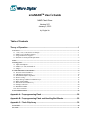
1
smxNANDTM User’s Guide
NAND Flash Driver
Version 2.01
January 3, 2012
by Yingbo Hu
Table of Contents
Theory of Operation ...................................................................................................... 1
1. Overview...............................................................................................................................................................1
1.1 v1.80, v1.90, v2.00, and v2.01 Changes .........................................................................................................1
1.2 Multi-Level Cell (MLC) Support ...................................................................................................................1
1.3 Large Flash Device Support ...........................................................................................................................1
1.4 Flash Device and System Requirements.........................................................................................................2
2. Files .......................................................................................................................................................................2
3. Porting Notes........................................................................................................................................................3
3.1 fdport.h and fdport.c .......................................................................................................................................3
3.2 nandio.c (or .asm) and nandio.h......................................................................................................................3
3.3 fdcfg.h.............................................................................................................................................................6
4. NAND Flash Driver Introduction ......................................................................................................................8
4.1 Structure of the Flash Driver ..........................................................................................................................8
4.2 LRU Block Cache System ............................................................................................................................10
4.3 Flash Block Replace Algorithm....................................................................................................................11
4.4 Wear Leveling ..............................................................................................................................................12
4.5 Physical/Logic Address Translation Layer ...................................................................................................13
4.6 Block Table Handler.....................................................................................................................................13
4.7 Data Protection and Recovery ......................................................................................................................17
4.8 Garbage Collection .......................................................................................................................................20
4.9 Bad Block Handler .......................................................................................................................................20
4.10 Error Correction..........................................................................................................................................21
5. Size and Performance........................................................................................................................................24
Appendix A: Preprogramming Flash ........................................................................ 28
Appendix B: Preprogramming Flash and Handling Bad Blocks ............................ 29
Appendix C: Flash Chip Array .................................................................................. 30
C.1 Parallel.............................................................................................................................................................30
C.2 Serial ................................................................................................................................................................31
© Copyright 2004-2012
Micro Digital Associates, Inc.
2900 Bristol Street, #G204
Costa Mesa, CA 92626
(714) 437-7333
[email protected]
www.smxrtos.com
© Copyright 1999-2004
OSIA Technology
All rights reserved.
smxFFS is a Trademark of Micro Digital Inc.
smxNAND is a Trademark of Micro Digital Inc.
smx is a Registered Trademark of Micro Digital Inc.
Theory of Operation
1. Overview
smxNAND is a NAND flash driver that is built-into smxFFS and an optional driver for smxFS. Previously, this
driver was documented in the smxFFS manual, but it was split out for the benefit of smxFS users.
1.1 v1.80, v1.90, v2.00, and v2.01 Changes
v1.80 and later are incompatible with older versions of smxNAND, since changes were made to the low-level
flash format. To upgrade to a newer version, you must reformat your flash disk. There are several improvements
and changes made in these versions:
•
•
Spare area data read/write operations are 16-bit aligned so it can support 16-bit bus NAND flash chips
better.
Multi-level cell (MLC) support changes were made in v1.80 but support was not complete until v1.90.
v2.00’s porting layer was changed to use smxBase.
v2.01’s API names changed to be consistent with smxNOR (with prefix nand_IO_ and nand_), and all files were
moved from directory XFFS to XFD.
1.2 Multi-Level Cell (MLC) Support
Note:
smxNAND has not been tested on MLC flash. It has been tested with MLC simulation and on new SLC
flash that has similar characteristics, such as the requirement for sequential page programming. If your
design uses MLC flash, we will support you to get it working, but we recommend using SLC flash.
Starting with v1.90, smxNAND supports Multi-Level Cell NAND flash. This flash achieves much higher flash
density than Single-Level Cell (SLC) flash, so the capacity can be much higher in a package the same size.
However, MLC flash has many limitations compared to SLC. Probably most significant is that it is highly unreliable
and requires at least a 4-bit ECC vs. SLC which (in our experience) rarely has errors and 1-bit ECC sufficient.
Calculating 1-bit ECC in software is reasonable, but 4-bit is impractical because it puts an enormous load on the
processor (nearly a billion instructions to calculate one block (256KB) ECC!). It reduces performance to a crawl.
For MLC, you really need to use a hardware 4-bit (or better) ECC controller, which may be combined with an MLC
NAND controller. This may be built into your processor, available as an external chip, or available as IP for your
custom ASIC or FPGA.
Another significant limitation is that page programming must be sequential, and it is not possible to do any partial
programming. Even the spare area must be written at the same time as the data area. To support MLC we had to
modify the block table handling algorithm which makes it wear the flash a little more and waste some flash (using a
whole pages to store flags rather than just bytes in the spare area, for example).
Please see our whitepaper “MLC vs. SLC NAND Flash in Embedded Systems”
(www.smxrtos.com/articles/mlcslc.htm) for more information before you decide to use MLC in your system.
1.3 Large Flash Device Support
Starting with v1.60, smxNAND supports very large NAND flash devices (or arrays of many flash devices), which
have more than 16K blocks. Set NAND_SUPPORT_LARGE_BLOCKNUM to 1 in fdcfg.h if your flash device’s
block number is larger than 16K (214), In this case, the block table nodes and wear counters are each 32-bit.
1
1.4 Flash Device and System Requirements
This is a list of requirements that your flash device and target system must meet in order to be able to use
smxNAND. The details are given in the text below; here we just summarize:
•
•
•
•
•
NAND flash only
For SLC (Single Level Cell) flash:
o At least 16-byte spare area in each page, for flash with 512-byte page size (see note 1)
o Ability to read/write the spare area of each page independently of the rest of the page
o Must support partial programming to a page spare area at least 3 times (see section 4.7 Data
Protection and Recovery)
o Must support non-sequential programming of pages (i.e. writing to different pages in any order).
See note 3 below for SLC flash that does not meet all these requirements.
Maximum flash media size is the lesser of 230 * block_size bytes or block_size/8 * block_size bytes. Up to
512GB is supported for flash media with a 2MB block size (see note 2).
128MB with 16KB block size flash is NOT supported because the Block Table needs to fit within 1 block,
but for that configuration, the Block Table would need to use two blocks (4*8192=32KB). 128MB with
128KB block size flash is supported and has been tested.
RAM requirement: See section 6 below.
Notes:
1.
The spare area is used to store the 6-byte meta information of the page and ECC codes. The ECC codes require
3 bytes (SLC) or 6 bytes (MLC) per 256 bytes. For SLC chips page size larger than 512 bytes, ECC uses 3 *
page_size/256 bytes. Example: 2048-byte page size requires 6 + 3 * 2048/256 == 30 bytes. MLC flash uses 54
bytes for ECC. See section 5.10 Error Correction.
2.
“Maximum flash media size” means the total size of all flash devices. If
NAND_SUPPORT_LARGE_BLOCKNUM is 1, Block Table enries are 32-bit and the upper 2 bits are used as
flags, so there is a maximum of 230 entries. Also, the complete Block Table and Wear Counter Array must be
stored in a single flash block, and since each block table entry is 4 bytes and each wear counter is also 4 bytes,
the maximum number of blocks is further limited to blocksize/8. See sections 4.3 Flash Block Replace
Algorithm and 4.4 Wear Leveling. If NAND_SUPPORT_LARGE_BLOCKNUM is 0, Block Table entries and
Wear Counters are 16-bit and the upper 2 bits are used as flags, so the maximum is 214 * block_size bytes or
block_size/4 * block_size bytes.
3.
For SLC flash that does not meet all the requirements listed above, smxNAND may be able to support it by
enabling MLC_FLASH in flashcnf.h. This uses modified algorithms that work for MLC flash. This is
something you might do if you already designed the flash into your board and it cannot be changed, not
something you should do if you have a choice, since it is slower, wastes flash, and wears the flash faster. See
1.2 Multi-Level Cell (MLC) Support for details.
2. Files
fd*.* are part of smxFD but contain some things needed by smxNAND.
FILE
DESCRIPTION
nandio.c
(nandio.asm)
nandio.h
Low-level flash access functions for NAND flash. This file depends on how
the user designs his hardware.
Low-level flash access function declarations for NAND flash.
nandfd.c
nandfd.h
nandecc.c
nandecc.h
Flash driver’s function implementations.
Flash driver’s API prototype declarations.
Software ECC code (1-bit for SLC and 4-bit for MLC).
Software ECC API prototype declarations.
2
fdcfg.h
fdport.c
fdport.h
EMU\*.*
Flash driver (smxNAND and smxNOR) configuration file. The user can
change the constants without the need to change the source code.
Flash driver (smxNAND and smxNOR) OS-dependent function
implementations. Based on smxBase.
Flash driver (smxNAND and smxNOR) OS-dependent function prototypes
and data type declarations. Based on smxBase.
Emulator files to debug FFS on hard disk
3. Porting Notes
The porting layer consists of these modules:
3.1 fdport.h and fdport.c
The flash driver’s porting layer maps onto smxBase services. Please see the smxBase User’s Guide for detailed
information.
3.2 nandio.c (or .asm) and nandio.h
These contain the functions that are specific to the NAND flash hardware design. The functions listed in nandio.h
are the ones that need to be ported or implemented to run on a different flash device and/or a different hardware
design. nandio.c contains the sample code for those low level functions, it supports 512 byte or 2K page size, and 8or 16-bit bus.
We assume that you are familiar with NAND flash and how it works. We have tested our implementation for
Samsung, Toshiba, SanDisk, and Fujitsu NAND flash of 4, 8, 16 and 32 MB size and Samsung, STMicro, Micron,
and Numonyx 64MB, 128MB (128KB block size), 256MB, and 1GB size.
IMPORTANT:
1.
Your flash chip and hardware design MUST support reading and writing the spare area of each page
independently of the rest of the page. One way to do this is to control the SE pin of the NAND flash chip
and/or issue a different flash command. Our flash driver uses the spare area to store some additional
information. Our general NAND flash driver sample code uses polling to check the R/B signal not the
interrupt. You can use the interrupt by modifying the sample code. We tested the interrupt-driven driver on the
AT91SAM9263EK board. You can ask us for that particular driver as a reference to implement your interruptdriven driver. Normally erase block needs to wait a few milliseconds, and page program needs to wait a few
hundred microseconds. These are long enough to be worth using the interrupt. Page read only needs to wait a
few microseconds, so the overhead of the interrupt handler will decrease the performance 15% to 20% in our
testing.
2.
The code in nandio.c is only sample code. It works for a lot of hardware but may not work for yours. It is
written for hardware that directly connects the NAND flash chip to the microprocessor’s data and address
buses. You can use it as a starting point and modify some macros that are related to the hardware design, such
as the base address and GPIO setting. If you are using a different interface, such as a built-in NAND flash
controller or FPGA, or if you want to use DMA to transfer data between your processor and flash chip, you
need to implement a new driver. You only need to follow the function prototypes defined in nandio.h.
3.
If you are using hardware ECC, for example, a built-in flash controller such as the one on i.MX31 or
LPC3180/3250, or if the flash chip has a built-in ECC engine, you need to disable the software ECC and
implement the hardware ECC generation and result check in the low level driver. If the data is correct, return 0.
If the error is correctable then return RESULT_ECC_FAIL (defined in nandio.h) for nand_IO_Read_Page().
Otherwise, return RESULT_FAIL so the flash driver will do the proper block replacement handling.
3
Basic functions include:
nand_IO_Flash_Reset (uint iChipID);
Reset the flash hardware. Normally issues the 0xFF command to the chip. Please refer to your hardware
spec for details.
nand_IO_Flash_Init (void);
Initialize the interface hardware between your processor and the NAND flash chip, such as GPIO and MMU.
nand_IO_Read_Device_ID (uint iChipID, DEVICE_INFO pDeviceInfo);
Read the device ID so the flash driver can retrieve the hardware information into the DeviceInfo structure.
Please refer to the DeviceInfo definition to see which information is needed by the flash driver.
nand_IO_Write_Page (uint iChipID, byte * write_data, uint32 page_index, uint offset, uint32 data_size);
Write some data to the NAND flash. The flash driver ensures that the whole block is already erased before
writing to it. Please do not erase it before writing to it. Page_index and offset can be used to generate the
physical address you want to write to.
Parameters:
iChipID
write_data
page_index
offset
data_size
The chip index you want to use. Currently only pass 0.
Pointer to the source buffer
Page index number.
Offset from the beginning of the main data area. Currently only pass 0.
Data size to be written. According to the spec for NAND flash, the data_size can be from
1 to page_size + spare_area_size. If the page size is 512 bytes and spare data size is 16
bytes, the data_size can up to 528 bytes. Currently only pass 512/2048 or 528/2112.
Return value:
If the write operation failed, it should return a non-zero value. Otherwise it should return 0.
nand_IO_Read_Page (uint iChipID, byte * read_data, uint32 page_index, uint offset, uint32 data_size);
Read some data from the NAND flash.
Parameters:
iChipID
read_data
page_index
offset
data_size
The chip index you want to use. Currently only pass 0.
Pointer to the target buffer
Page index number.
Offset from the beginning of the main data area. Currently only pass 0.
Data size to be read. According to the spec for NAND flash, the data_size can be from 1
to page_size + spare_area_size. If the page size is 512 bytes and spare data size is 16
bytes, the data_size can up to 528 bytes. Currently only pass 512/2048 or 528/2112.
Return value:
RESULT_OK if data is correct.
RESULT_FAIL if data is incorrect and can not be corrected by ECC
RESULT_ECC_FAIL if the data is corrected by ECC but it is better we should move the data in that
block to another empty block to prevent further damage to the data.
nand_IO_Write_Page_Spare (uint iChipID, byte * write_data, uint32 page_index, uint offset, uint32
data_size);
Write some data to the NAND flash spare area. The flash driver ensures that the whole block is already
erased before writing to it. Please do not erase it before writing to it.
Parameters:
iChipID
The chip index you want to use. Currently only pass 0.
write_data Pointer to the source buffer
page_index Page index number.
4
offset
data_size
Offset from the beginning of the spare area. It must be 16-bit aligned, for example, 2, 4,
or 6 for v1.80 or later. This is used to avoid the location where the hardware ECC is
written (if you use a NAND controller that does ECC).
Data size to be written. According to the spec for NAND flash, the data_size can be from
1 to spare_area_size. If the spare data size is 16 bytes, the data_size can up to 16 bytes.
For v1.80 and later, data size is always 16 bits, that is, 2.
Return value:
If the write operation failed, it will return a non-zero value. Otherwise it will return 0.
nand_IO_Read_Page_Spare (uint iChipID, byte * read_data, uint32 page_index, uint offset, uint32
data_size);
Read some data from the NAND flash spare area.
Parameters:
iChipID
read_data
page_index
offset
data_size
The chip index you want to use. Currently only pass 0.
Pointer for the target buffer
Page index number.
Offset from the beginning of the spare area. It must be 16-bit aligned, for example, 2, 4,
or 6 for v1.80 or later. This is used to avoid the location where the hardware ECC is
written (if you use a NAND controller that does ECC).
Data size to be read. According to the spec for NAND flash, the data_size can be from 1
byte to spare_area_size. If the spare data size is 16 bytes, data_size can up to 16 bytes.
For v1.80 and later, data size is always 16 bits, that is, 2.
nand_IO_Erase_Block (uint32 block_index);
Erase one flash block.
Parameters:
block_index Block index. You may need to generate the block address by multiplying it by block size.
Return value:
If the erase operation failed, it will return a non-zero value. Otherwise it will return 0.
You need to verify your implementation before you try any high level APIs such as smxFS, smxFFS, and smxFLog.
We provide sample code to verify if your porting of the IO routines is correct. Please run it first after you
complete your porting. Then test the integration with your file system. There are two ways you can run the
verification testing:
1.
If you purchased the standalone smxNAND driver without smxFS, smxFFS, or smxFLog, you need to copy
the code in function testNANDIO() in XFD\nandtest.c to your application and modify the output message
functions (print_err() and print()) to make them work on your system. Run it on your hardware and ensure
it does not report any problem. nandtest.c also provides other functions to help you verify the smxNAND
APIs and measure their performance. testNANDDriver() is used to test the NAND flash driver APIs.
testNANDIOPerformance() is used to test the performance of the IO routines.
2.
If you also purchased smxFS, smxFFS, or smxFlog, we also provide APP\DEMO\flltest.c for low-level
flash driver testing. In your project file or makefile, replace fsdemo.c, fstest.c, ffsdemo.c, fldemo.c, or
fltest.c with flltest.c, and rebuild the application. The low-level driver testing code will run instead of the
normal smxFS/FFS/FLog demo code.
Even you are running the driver verified by Micro Digital, we still recommend you run the low level testing code to
make sure it is working properly on your hardware.
5
3.3 fdcfg.h
This file contains configuration options for the NAND flash driver.
NAND_SUPPORT_LARGE_BLOCKNUM
Set to 1 if the block number of the flash chip is larger than 16K.
NAND_RETRY_TIMES
This is the number of times the low level IO routine should retry before it will report an error to the high
level code.
NAND_READ_BADBLOCK_INFO
If “1” the NAND flash driver will try to get the manufacturer’s marked bad block information the first time
the NAND flash driver mounts the chip. You also need to implement
NAND_Read_Chip_Bad_Block_Info() to get the bad block information because each vendor may use
different pattern to mark bad blocks.
NAND_READBACK_VERIFY
If “1” the driver will read back and verify all data written against the original data. Normally
nand_IO_Write_Page() will return an error code in the case of a program failure, but enabling this option
provides an extra check.
NAND_AUTO_FORMAT_FLASH
If “1” the NAND flash driver will automatically format the flash chip when it cannot find valid data
structures on it. smxNAND does NOT assume your NAND flash is empty. If you have some preloaded
data on that flash or run some 3rd party test code on it that does not erase the flash after it is done, it is
necessary to erase the flash. If smxNAND cannot find valid data structures (block table) on it, and if this
flag is set to 1, smxNAND will erase the flash for you.
NAND_MLC_FLASH
Set it to “1” if your flash chip is a MLC instead of SLC flash. The NAND flash driver will use a different
approach to update the block table and to ensure sequential programming of pages in a block. See 1.2
Multi-Level Cell (MLC) Support.
NAND_USE_SOFT_ECC
If “1” software ECC generation for write and correction for read is enabled. Otherwise, code ot use
hardware ECC should be added to the low level routine.
NAND_CACHE_BLOCK_NUMBER
Number of cache blocks. Increase it to improve performance if you are accessing multiple files
simultaneously
NAND_PAGES_PER_CACHE_BLOCK
Number of pages to cache in each cache block. If 0, the whole flash block is cached in each cache block.
Must be power of 2
NAND_USE_SECOND_BLOCK_TABLE
If “1” and you are not using whole flash block cache and it is not a MLC flash, a second block table will be
used to improve the performance of data write.
NAND_SECOND_BLOCK_TABLE_NUM
Number of second block table blocks.
NAND_BLOCK_TABLE_INDEX
Block table block logical index. Normally it should be less than RESERVED_BLOCK_NUM.
6
NAND_BACKUP_BLOCK_INDEX
Backup block table block logical index (to use when the whole flash is full). Normally it should be less
than RESERVED_BLOCK_NUM.
NAND_RESERVED_BLOCK_NUM
Number of reserved blocks for the block table and other system purposes, such as boot loader. Normally it
should be greater than 1.
NAND_START_BLOCK_NUM
Block index of the start of the smxNAND partition. Should be greater than RESERVED_BLOCK_NUM.
NAND_RESERVED_DATA_BLOCK_NUM
Number of reserved blocks used for replacement of bad blocks. It must be larger than the maximum
expected number of bad blocks for your flash chip’s whole life cycle.
NAND_WEAR_LEVELING_GATE
Static wear leveling trigger gate. If the wear level difference exceeds this gate, the NAND flash driver does
static wear leveling
NAND_WEAR_LEVELING_BLOCK_NUM
Maximum number of blocks the NAND flash driver will move during static wear leveling. Increasing it
will increase the static wear leveling time and may add additional file system operation latency.
7
4. NAND Flash Driver Introduction
The Flash Driver makes it appear to the File System as if the flash is an array of read/write units like a disk. This is
difficult because flash bytes cannot be written and rewritten like a disk or RAM. Before a byte can be rewritten, the
block it is in must be erased. This is because a write operation can only change a bit from ‘1’ to ‘0’. Bits are changed
back to ‘1’ only by erasing the whole Block, which is the smallest erasable unit of flash. In order to change a byte in
a block, it is necessary to read the whole block into a buffer, change the byte in the buffer, erase the flash block, and
then write the updated buffer back to the block. Because this is time-consuming and wears out the flash, the Flash
Driver minimizes how often this is done.
A Block is divided into some number of Pages (e.g. 16 or 32). Each page can be separately read/written. You can
read/write any number bytes of a page, anywhere in the page. However, you can only write to a particular page a
specified maximum number of times (to different areas) before erasing it. For example, if the page is blank, it is
possible to write the first 10 bytes and then the last 10 bytes. This feature is called partial programming. The number
of times partial programming can be done to a page depends on the flash chip being used. Please refer the data sheet
of your chip to determine this. This Flash Driver requires that it must be at least 3 for SLC flash. Each page also
contains a spare data area (e.g. 16 bytes), which is used by the flash driver to record additional information such the
status and ECC.
Another difficulty of flash is that there is a finite limit to the number of times a byte of flash can be rewritten before
it fails. To extend the life of the flash, the Flash Driver must try to wear the flash evenly.
The Flash Driver hides all of these complexities.
4.1 Structure of the Flash Driver
The Flash Driver contains the following layers:
Least-Recently Used (LRU) Block Cache System,
Flash Block Replace System (wear leveling and reclaim),
Physical/Logical Address Translation Layer,
ECC Generation and Checking,
Block Table Handler (data protection/recovery, garbage collection),
Bad Block Handler, etc
Figure 6 shows the structure of the Flash Driver.
8
High Level Application such as File
system, Data storage.
Page Read/Write Routine Interface
LRU Block Cache System
Maps Page Read/Write Requests to
Cache Blocks
Flash Block Replace Algorithm
Dynamic Wear Leveling
Physical/Logical Address Translation
Layer
Block Table Handler
Data Protection/Recovery
Garbage Collection
Static Wear Leveling
ECC Generation and Checking
Bad Block
Handler
NAND Flash Low Level I/O Routines
Figure 6: Flash Driver Structure
The NAND Flash driver provides only these functions to the high level application to access data:
nand_Page_Read()/nand_Sector_Read() and nand_Page_Write()/nand_Sector_Write(). The application can only
access the NAND Flash by page/sector. The Flash Driver uses a Least Recently Used (LRU) Cache system to hold
full or partial flash blocks and reads/writes the pages in them. A cache block can be as small as 1 page or as big as a
flash block (it must be a power of 2 * page size). Other parts of the Flash Driver always use the block as the physical
data read/write unit, since the NAND flash can only be erased by block. Although the Cache system may only
cache parts of a block, when writing it back, the whole physical block’s data will be updated at the same time.
That is, the data, which are not in the Cache system, will be read from the old flash block and then copied to
the new flash block. This also simplifies the reclaim and garbage collection procedures. When writing new data to
an empty flash block, only the pages with valid data are written. Later, new data can be written to the remaining
empty pages, since pages can be written independently.
9
4.2 LRU Block Cache System
Because of the way NAND flash works, to write data to an area, the area must be pre-erased (all bytes set to 0xFF).
To improve performance, the system caches the currently active pages in RAM and flushes them to the flash device
only when necessary.
You can select to cache the whole block or only some pages. The macro PAGES_PER_CACHE_BLOCK is used to
control this. For example, set it to 0 to cache a whole flash block; setting it to 2 means to cache only 2 pages of a
flash block. It must be set to a power of 2. 0 is the default and recommended value for flash chips with a block size
less than 32KB. If you are using a NAND flash that has a large block size, for example 2KB page size and 128KB
block size, you can set it to 4, and then you only cache 4 pages (8KB). CACHE_BLOCK_NUMBER in flashcnf.h
specifies how many cache blocks of size PAGES_PER_CACHE_BLOCK are stored in the cache. If RAM is tight in
your system, consider the following guidelines when configuring these settings:
•
•
•
If your flash device’s block size is 8KB or less, we strongly recommend that you use 2 cache blocks that
are each the size of a flash block (i.e. 2 x 8KB).
If the block size is 16KB, we recommend at least 2 cache blocks each of size 8KB.
In general, it is best if the total cache size is at least as big as a flash block or performance may suffer.
Cache blocks are replaced according to the Least Recently Used (LRU) algorithm. Figure 7 shows the LRU Block
Cache Flow Chart:
Read/Write one Page of data
from/to the Flash Device
No
Is the Page
currently in the
Cache? (cache
hit)
Yes
Find the Cache Block to
be replaced according to
the LRU value
Yes
Flush (write)
Cache Block
contents to
Flash Device
Is the
“Changed”
Flag set?
No
Discard old Cache
Block contents
Copy the page data
from/to the Cache,
increase the LRU
value. If Write, set
the “Changed” Flag
Read new Cache Block
from Flash Device
Return
Figure 7: LRU Block Cache Flow Chart
10
4.3 Flash Block Replace Algorithm
When the contents of a block are changed, whether modifying the data there or adding to it, the flash driver will
never write the data to the same place, since data in flash cannot be overwritten. Instead, a spare block is found (that
has not been written to and is the least worn of all spare blocks), and the data (with corrections) is written to this
new block. Then the old block is marked as discarded. The old data in the original block is not changed at all. This
algorithm reduces memory demands and avoids excessive block usage. There are two situations in which the block
will not be replaced:
A. The target block is already a spare block or
B. The new added data will be written to a spare page (i.e. one that is still erased). (The system will directly
write the data to the spare page without the need to erase it.)
The algorithm uses the Block Table to find a spare block and to mark the old block as discarded. The system uses
the spare area of each flash page to record the current page status so the system knows which pages are blank (can
be immediately written to) and which pages need to be erased first. The algorithm tries to find a spare block that has
been used least recently so it can provide wear leveling support. Figure 8 shows the structure of a Block Table entry.
2 bits
Block
Status
14 or 30 bits
Block Physical Index
Figure 8: Block Table Entry Structure
The Block Table entries are each 16 bits in the normal configuration or 32 bits if
SUPPORT_LARGE_BLOCKNUM is enabled in flashcnf.h. The highest 2 bits are reserved for the status of the
Block. The low 14 or 30 bits are the physical index of the block. The system can calculate the physical address of
the block. The highest 2 bits are defined as:
00b
10b
01b
11b
used block; this block contains valid data
discarded block; this block contains old data and needs to be erased
spare block; this block is empty (erased)
bad block; this block contains error bits and should not be used anymore
Note: If you enable SUPPORT_LARGE_FILESYS and SUPPORT_LARGE_BLOCKNUM in ffsdefs.h and
flashcnf.h, then for a 2MB block size, up to 512GB flash is supported. (Each block node plus wear counter is 8
bytes, so a 2MB block can store 256K block table and wear counter entries, which gives a 512GB total flash
size.)
Figure 9 shows the Flash Block Replace procedure. The new/modified data (green color) is written to a new block
(M) and the old data block (N) (yellow color) is unchanged.
11
New
Data
Media
Block Table
..
..
..
..
..
..
Block N
0x10
(used)
Node N
0x34
(=0x0010)
..
..
..
Block M
0x20
(least used
spare block)
..
..
..
Block Table
Media
..
..
..
..
..
..
Node N
0x34
(=0x0020)
Block N
(discarded)
Other used
or
discarded
Nodes
Other used
or
discarded
Nodes
..
..
..
Node M
0x78
(=0x4020)
Node M
0x78
(=0x8010)
Block M
(used)
..
..
..
..
..
..
..
..
..
Find the
least used
apare block,
switch the
index, mask
the status
bits
Figure 9: Flash Block Replace Procedure
During the block update, for SLC flash, if the cache size is less than one block, we will use SecondBlockTable
algorithm to only update the changed page. We will not write the unchanged page to the new block. By doing that, if
the next write operation is to the unchanged page of the same block, we don’t need to write the whole block of data
again just because of a cache miss. This algorithm will greatly improve the performance of a file append operation.
The SecondBlockTable item number is defined in flashcnf.h, SECOND_BLOCK_TABLE_NUM. Normally this
setting should be the same as the cache size, CACHE_BLOCK_NUMBER.
For MLC flash chip, because of the limitation of MLC page programming, we cannot use this SecondBlockTable
algorithm. You need to either cache whole block or we need to update the whole block at once even though only one
page was changed. Since a cache block can be smaller than a flash block (its size is specified in pages), there could
be multiple cache blocks from the same flash block. These are all written to the flash block at once. This is the
sequence of operations: The old block is processed page by page, starting with page 0. If the page is in the block
cache, the data is copied from the block cache into the new flash block. Otherwise, it is copied from the old flash
block. This process is repeated for each page of the old block.
4.4 Wear Leveling
NAND flash memory has limited life expectancy. For any given flash device, there is a limitation to the total
number of erase operations that may be performed on a particular block before it becomes unreliable or damaged.
Flash device lifetimes range from 10,000 write-erase cycles to 1,000,000 cycles, with most rated around 100,000.
When a flash block approaches its rated limit, it may begin to fail or take longer to perform operations. To maximize
the life cycle of a NAND flash device, it must be wear-leveled. Wear leveling is the process of ensuring all blocks
are erased with the same frequency.
Wear-leveling, performed during the garbage collection process, evens usage across the blocks of a flash memory
array and so compensates for the finite number of erase cycles available throughout its life. An effective system of
wear-leveling must address three major issues:
a.
b.
c.
The writing of data cannot be confined to only a certain location in the flash.
Static data in the flash must be moved periodically.
Block deadlocks must be avoided.
12
smxNAND records a wear counter for each block that indicates how many times the block has been written. An
array of these counters is stored in the flash, immediately following the Block Table, so this information is retained
even with power off. The wear counter for a block is incremented each time the block is written. Since each wear
counter is only 16 or 32 bits (just like the Block Table entries), a counter could overflow. smxNAND prevents this
by periodically reducing all counters by the value of the least-worn counter. The Block Table and Wear Counter
Array are treated as a unit; each time the Block Table is written to a new location, the Wear Counter Array is too.
See the Block Table Handler section, below, for more information.
Static files that don’t change, such as the application file, font files, icons, etc, and files that are rarely changed must
be periodically moved, so all flash blocks in the flash device are evenly worn. smxNAND moves these blocks
during garbage collection. Since it takes time to move blocks (and wears the flash), this must not be done too
frequently or system performance will degrade. This is controlled by two configuration settings. The first setting,
WEAR_LEVELING_GATE specifies when to do it: If the difference between the most worn-counter and leastworn counter exceeds this value, some of the static blocks are moved. The second setting,
WEAR_LEVELING_BLOCK_NUM, specifies the maximum number of static blocks to move each time. Each time
garbage collection is done, more of the remaining static blocks are moved.
4.5 Physical/Logic Address Translation Layer
In the Block Table, the system records the Flash Block index in the low 14 or 30 bits so the system can compute the
physical device address for the memory space. Figure 10 shows how a Logical address is converted to a Physical
address by the Block Table.
Logical Memory
Block Table
Physical Memory
..
..
..
..
..
..
..
..
..
Block 10
Node 10
0x0014
Block 10
..
..
..
..
..
..
..
..
..
Block N
Node N
0x0010
Block 14
..
..
..
..
..
..
..
..
..
Figure 10: Logical addresses are converted to Physical addresses by the Block Table
4.6 Block Table Handler
The Block Table is the most important data structure in the Flash Driver, so the system must guarantee it is always
correct even if power is lost or the flash memory is full. Normally the Block Table (and Wear Counter Array) is
stored in a data block (in the Data Area) but in extreme cases when the flash is full, it is stored in the Reserved Area
at the beginning of the flash memory. Almost all NAND flash chips guarantee that block 0 is good. So it is safe to
store the Block Table to block 0.
The size of the Reserved Area is defined by RESERVED_BLOCK_NUM in flashcnf.h. If the user wants to reserve
additional blocks for application use, define the macro START_BLOCK_NUM to be greater than
13
RESERVED_BLOCK_NUM. The flash driver only uses blocks greater than START_BLOCK_NUM for the Data
Area. This is shown in Figure 11.
RESERVED_BLOCK_NUM
Reserved Area
by Flash Driver
S
Reserved Area
by User
START_BLOCK_NUM
Data Area
controlled by
the NAND
Flash Driver.
Figure 11: Physical Memory Map of the NAND Flash Driver
The Data Area holds everything else that should be handled by the file system. Figure 11 shows the low-level
NAND driver view.
smxNAND was designed to avoid having its data structures remain in the same location in the flash, since these are
written frequently, which would wear out the flash faster in these areas. Hence, the Block Table and Wear Counter
Array must be able to move in the flash, as well. A whole block is allocated to store the Block Table and Wear
Counter Array even though they may be much smaller than a block. This allows both to be written several times to
the same block as they are updated. When a new Block Table and Wear Counter Array needs to be written, the
system selects the next spare (empty) pages in the block and then writes to this new place. This algorithm assumes:
a.
b.
The combined Block Table and Wear Counter Array is always page aligned and
Separate flash pages can be written separately.
Once the Block Table has been written to a new block, the old block is marked as discarded so it can be re-used later
to store other data.
This algorithm provides:
a.
b.
Wear leveling for the Block Table area, to avoid writing data to the same area, which would reduce the life
of the flash device.
Data protection — the old Block Table is never destroyed until the new one has been successfully written
to the new place. If any error occurs during this phase, the data can be restored to previous status.
For example, a 16MB flash device has 1024 blocks, so the Block Table size is 1024 * 2 == 2048 bytes, and the
Wear Counter Array size is 1024 * 2 == 2048 bytes. The total size is 8 pages. Each block has 32 pages. The Block
Table update procedure is shown in Figures 12a (SLC) and 12b (MLC).
14
Block Table block
Block Table & Wear
Counter Array
Write New Block Table Contents
Discarded Block Table &
Wear Counter Array
Block Table & Wear
Counter Array
Spare Pages
Update Block Table Twice
Discarded Block Table &
Wear Counter Array
Discarded Block Table &
Wear Counter Array
Discarded Block Table &
Wear Counter Array
Block Table & Wear
Counter Array
Old Block should be marked as
discarded for the next write operation
Discarded Block
Figure 12a: How the Block Table is Updated (SLC)
So for the 16KB block size flash, we can only support up to 64MB flash size. 128MB flash cannot be supported if
the block size is only 16KB because the block table needs 8192*4=32KB data which requires two physical blocks.
128KB block size should be fine and most current 128MB flash chips use 128KB block size.
Since the Block Table can be anywhere in the Data Area, the system uses a special flag to indicate where it is. This
flag is stored in the second byte in the spare area of the last page of the Block Table. This flag is unique and will not
be used by other data blocks. During initialization, smxNAND scans the entire flash memory array, checking all the
possible positions that may contain this flag. If it is found, smxNAND will try to read the information and determine
if it is valid. For details, refer to the following section. See Figure 12c for details about how the status byte is
updated in the spare area for SLC flash.
15
MLC Flash
Because MLC flash does not support partial programming and all data write operations must be done sequentially
from LSB to the MSB, a little modification is needed to update the block table for MLC flash. (Please see the next
section for discussion of the Valid, In-Progress, and Discarded status flags.)
A. We cannot use the same spare area to mark In-Progress and Discarded status of the block table because we
cannot do partial programming. So for each block table, we need one additional page to write the In-Progress
status. We put the In-progress status at the first page’s spare are after the block table.
B. To save the overhead, we don’t write the discarded status unless the whole physical block should be discarded.
When we initialize the flash driver. If we find an In-progress status. We will check the next possible block table
Valid status. If we find a valid status. We know that the In-Progress Block Table is actually a discarded block
table and we need to ignore it. If we found a discarded status at the end of that block then we know we should
ignore the whole block.
Block Table block
Block Table & Wear
Counter Array
Spare Pages
Spare Pages
Spare Pages
Write New Block Table Contents
Discarded Block Table &
Wear Counter Array
Block Table & Wear
Counter Array
Spare Pages
Spare Pages
Update Block Table Twice
Discarded Block Table
& Wear Counter Array
Discarded Block Table
& Wear Counter Array
Discarded Block Table
& Wear Counter Array
Block Table & Wear
Counter Array
Discarded Block Table
& Wear Counter Array
Discarded Block Table
& Wear Counter Array
Old Block should be marked as
discarded for the next write operation
Discarded Block Table
& Wear Counter Array
Discarded Block Table
& Wear Counter Array
Cyan box represents the Valid status in the last page’s spare area. Red box represents the In-Progress status page.
Blue box represents the Discarded status page. It is the last in the group of pages.
Figure 12b: How the Block Table is Updated (MLC)
See Figure 12d for details about how the status byte is updated in the spare area for MLC flash.
16
4.7 Data Protection and Recovery
The NAND flash driver must ensure data is never lost. The Flash Block Replace algorithm provides some data
protection because it will not destroy the old data before the new data is successfully written into the flash . The
Block Table is used to provide the data protection and recovery method. The algorithm is:
Before any data is to be written to the flash or before the Block Table is updated, the current Block Table (in flash)
is first marked as “In-Progress”. When the Block Table is successfully updated, the old Block Table (in flash) is then
marked as “Discarded”. The system uses the spare area of the last page of the Block Table to mark the status of the
Block Table. The status value is defined as follows:
0x7F
0x7E
0x00
Valid. This is the current Block Table.
In-Progress. The Block Table is being moved.
Discarded Block Table.
We write each status value to a different offset in the last page’s spare area. Valid status is at offset 0, In-Progress is
at offset 2 and Discarded is at offset 4. (The values are defined as they are because in early versions of smxNAND,
we wrote the status 3 times to the same location, but we found this was unreliable.) In order to do this, the flash
chip must support partial programming to a page at least 3 times. Writing the data and the Valid status are done
together as the first partial programming. Writing In-progress status is the second partial programming, and Writing
Discarded status is the third partial programming.
If any exception occurred during a write operation, there will always exist an In-Progress block table status but no
Discarded status. When the NAND flash driver is initialized the first time, the system checks to see if an In-Progress
Block Table exists. If so, the system knows the last operation did not complete and some checking must be done.
Specifically, the flash driver does the following:
A. Accept the “In-Progress” Block Table as the current valid Block Table. First, it is copied to another spare
block. Then the old block is erased to ensure Block Table integrity is OK.
B. Check every Spare Block to ensure it is really spare (empty) because the last write operation may have
been writing some data to the block but it did not complete, so the status in the Block Table was not
updated correctly.
After the above checking, the data has been restored to the last valid status. The only problem might be that data in
the cache that had not been flushed will be lost, but the filesystem will be intact.
The following diagrams show how the status byte is updated in the spare area for SLC and MLC flash.
17
Last page of the
current block table
Next block table
Main Area
Spare Area
Valid Status and Block Table Flag
Last page of the block
table that will be updated
Main Area
Next block table
Spare Area
In-progress Status
Last page of the block table
that has been updated
Main Area
New block table that is
being written
Spare Area
Discarded block table
Main Area
Current block table
Spare Area
Discarded Status
Figure 12c: How the Status Byte is Updated (SLC)
18
Last page of the
current block table
Main Area
In-Progress Status Page
Next block table
Spare Area
Valid Status and Block Table Flag
Last page of the block
table that will be
Main Area
In-Progress Status Page
Spare Area
Main Area
Next block table
Spare Area
In-Progress Status
Last page of the block table
that has been updated
Main Area
In-Progress Status Page
Spare Area
Discarded block table
Main Area
Main Area
Spare Area
In-Progress Status Page
Spare Area
Main Area
New block table that is
being written
Current block table
Spare Area
End of block
Discarded block table
In-Progress Status Page
Figure 12d: How the Status Byte is Updated (MLC)
19
Discarded Status Page
4.8 Garbage Collection
As mentioned before, the NAND Flash Driver only marks old data blocks as “discarded”. There should be a method
to erase the discarded block during the idle time to convert it to a spare block so it can be used for a future block
write operation. Garbage Collection performs this task. The Flash Driver, itself, does not provide automatic garbage
collection because it does not know when the system is idle. It only provides a function named
nand_Whole_Cache_Write_Back(). This function flushes the cache (writes the contents to flash) and does the
garbage collection procedure. It is the user’s responsibility to decide when to call this function. It should be called
when the whole system is idle. It is recommended that you call it when you close a file or finish some data
operation. This ensures the flash driver can work without any OS support.
If the file system is full, spare blocks are used from the Reserved Area, since a power fail during this time could
otherwise cause the system to lose important data. If no spare block is found during the Flash Block Replace
procedure, garbage collection is forced to run.
4.9 Bad Block Handler
If the low-level I/O routine returns an error for the write (programming) and/or erase operation, the system will retry
a few times. This is specified by RETRY_TIMES in flashcnf.h. If all retries fail, the system considers the block to
be a bad block. It will find a spare block from the end of the Block Table, write the whole data into the new block,
and then mark the old block as bad. Figure 13 shows the bad block handler procedure.
New
Data
..
..
..
..
Bad
Block
0x10
Block
Node
0x34
(=0x0010)
Find spare
block and
switch the
index value
..
..
..
..
..
Block
Node
0x34
(=0x0020)
Bad
Block
..
..
..
..
..
..
..
..
..
..
Spare
Block
0x20
Block
Node
0x78
(=0x4020)
Block
Node
0x78
(=0xC010
)
New
Data
..
..
..
..
..
..
..
..
..
Figure 13: Bad Block Handler Procedure
(The high 2 bits of the block node (e.g. the 4 in 0x4020) indicate the status of the block. See Figure 8: Block Table
Entry Structure.)
The bad block handler is transparent to the high level application. The application does not need to do any data
replacement operation.
Remember to set RESERVED_DATA_BLOCK_NUM in flashcnf.h to the maximum possible number of bad blocks
expected of your flash chip’s lifetime so the NAND flash driver will find spare blocks to replace bad ones. For
example, if your flash chip may have a maximum of 160 bad blocks at manufacture, we recommend you set
RESERVED_DATA_BLOCK_NUM to 200 to cover additional bad blocks during the normal usage.
20
4.10 Error Correction
After the NAND flash chip has been used for a long time, it may develop some bad bits. Normally for SLC flash
there is only one bad bit in a whole page but for MLC flash, there will be up to 4 bad bits. smxNAND implements
two software ECC algorithms capable of fixing a 1-bit error for SLC or 4-bit for MLC. The ECC code is 3 or 6 bytes
per 256 bytes, and the algorithm will detect if there are any error bits in the page. For SLC flash, if there is only a
1-bit error (from ‘1’ to ‘0’ or vice versa), ECC can also correct it. For MLC flash, if there is only a 4-bit error (or
less), ECC will correct it.
The ECC is generated before the data is actually written to the NAND flash chip. When data is read back from the
flash chip, if it has a correctable error, the corrected data is returned. If the data has an error that cannot be corrected,
an error is reported.
Our ECC algorithm will only process 256 bytes, but a page contains 512 bytes or a multiple of 512 bytes, so each
512 bytes of data requires two ECC codes: one for the first 256 bytes and the other for the second 256 bytes. The
ECC code is stored in the spare area of each page. Also a 6-byte metadata value is stored at the start of the spare
area. Please see the structure definition for PAGE_HEADER in flash.c for details. If your flash chip’s page size is a
multiple of 512 bytes, several ECC codes may be created in the spare area, so your flash chip must have spare areas
larger than 16 bytes. (The ECC codes require 3 or 6 bytes per 256 bytes, so ECC uses 3(or 6) * page_size/256 bytes,
and 6 bytes are required for reserved status. For example a 2048-byte page size SLC flash requires 6 + 3 * 2048/256
== 30 bytes in each spare area and a 2048-byte page size MLC flash requires 6 + 6 * 2048/256 == 52 bytes in each
spare area.) Normally, the manufacturer has handled this already. For example, if the page size is 2048, the spare
area is 64 bytes instead of the normal 16 bytes, which is plenty to store the ECC information.
4.10.1 1-bit ECC Code
We use a Hamming code to implement 1bit ECC.
A. ECC code consists of 3 bytes per 256 bytes
- Actually 22 bit ECC code per 2048 bits
- 22 bit ECC code = 16 bit line parity + 6 bit column parity
B. Data bit assignment table with ECC code
1st byte
2nd byte
3rd byte
4th byte
…………….
253th byte
254th byte
255th byte
256th byte
bit7
bit7
bit7
bit7
bit6
bit6
bit6
bit6
bit5
bit5
bit5
bit5
bit4
bit4
bit4
bit4
bit7
bit7
bit7
bit7
bit6
bit6
bit6
bit6
bit5
bit5
bit5
bit5
bit4
bit4
bit4
bit4
CP00
CP01
CP02
CP00
CP01
CP03
CP04
bit2
bit2
bit2
bit2
bit1
bit1
bit1
bit1
bit0
bit0
bit0
bit0
LP00
LP01
LP00
LP01
LP02
bit2
bit2
bit2
bit2
bit1
bit1
bit1
bit1
bit0
bit0
bit0
bit0
LP00
LP01
LP00
LP01
LP02
CP00
CP01
CP02
CP00
CP01
CP03
bit3
bit3
bit3
bit3
bit3
bit3
bit3
bit3
LP04
LP03
LP05
LP03
CP05
Column Parity is calculated over the entire data block as each data byte is processed. Selected bits of each data byte
are added to the previous value of each Column Parity bit. The equations for the Column Parity bits are:
CP00 = bit7 XOR bit5 XOR bit3 XOR bit1 XOR CP00
CP01 = bit6 XOR bit4 XOR bit2 XOR bit0 XOR CP01
CP02 = bit7 XOR bit6 XOR bit3 XOR bit2 XOR CP02
CP03 = bit5 XOR bit4 XOR bit1 XOR bit0 XOR CP03
CP04 = bit7 XOR bit6 XOR bit5 XOR bit4 XOR CP04
CP05 = bit3 XOR bit2 XOR bit1 XOR bit0 XOR CP05
21
Line parity is calculated over the entire data block as each data byte is processed. If the sum of the bits in one byte is
0, the line parity does not change when it is recalculated. The sum of the bits in 1 byte of data is:
Dall = bit7 XOR bit6 XOR bit5 XOR bit4 XOR bit3 XOR bit2 XOR bit1 XOR bit0
Sixteen line parity bits (LP15-LP00) are computed from 256 bytes of data. An 8 bit counter counts data bytes, bits of
this counter are used as a mask for Line Parity bits. The counter increments by 1 for each new byte of data. Line
Parity is computed by initializing all line parity bits to zero, reading in each byte, computing the byte sum (Dall),
and adding Dall to the line parity bits when they are enabled by the appropriate counter bits.
The equations for the Line Parity bits are:
LP00 = LP00 XOR (Dall AND Counter_bit0)
LP01 = LP01 XOR (Dall AND Counter_bit0)
LP02 = LP02 XOR (Dall AND Counter_bit1)
LP03 = LP03 XOR (Dall AND Counter_bit1)
LP04 = LP04 XOR (Dall AND Counter_bit2)
LP05 = LP05 XOR (Dall AND Counter_bit2)
LP06 = LP06 XOR (Dall AND Counter_bit3)
LP07 = LP07 XOR (Dall AND Counter_bit3)
LP08 = LP08 XOR (Dall AND Counter_bit4)
LP09 = LP09 XOR (Dall AND Counter_bit4)
LP10 = LP10 XOR (Dall AND Counter_bit5)
LP11 = LP11 XOR (Dall AND Counter_bit5)
LP12 = LP12 XOR (Dall AND Counter_bit6)
LP13 = LP13 XOR (Dall AND Counter_bit6)
LP14 = LP14 XOR (Dall AND Counter_bit7)
LP15 = LP15 XOR (Dall AND Counter_bit7)
C. Error detect case
LP
15
LP
14
LP
13
LP
12
LP
11
LP
10
LP
09
LP
08
LP
07
LP
06
LP
05
LP04
LP
03
LP
02
LP
01
LP
00
CP
05
CP
04
CP
03
CP
02
CP
01
CP
00
LP
15
LP
14
LP
13
LP
12
LP
11
LP
10
LP
09
LP
08
LP
07
LP
06
LP
05
LP04
LP
03
LP
02
LP
01
LP
00
CP
05
CP
04
CP
03
CP
02
CP
01
CP
00
code stored in
Flash
XOR
code read
generated
0
1
1
0
0
0
0
0
0
1
1
1
0
0
0
0
0
1
1
0
0
0
0
0
0
1
1
0
0
0
0
0
0
1
1
0
0
0
0
0
0
1
1
0
0
0
0
0
0
1
1
0
0
0
0
0
0
1
1
0
0
0
0
0
0
1
1
0
0
0
0
0
0
1
1
0
0
0
0
0
0
0
2
0
0
1
1
0
No Error
Correctable
Uncorrectable
Code Error
No error
Since there is no difference between the code stored in the flash and the one generated after the read, it is assumed
that there is no error in this case.
Correctable error
Since all parity bit pairs (CP00 and CP01),.....,(LP014 and LP15) have one error and one match in them as the result
of the comparisons between the code stored in flash and the one generated after the read, this case is considered to
be a correctable error.
Uncorrectable error
In this case, both CP00 and CP01 are in error as the results of the comparison between the code stored in flash and
the one generated after the read. This represents a multiple bit error, and is therefore uncorrectable.
ECC code area error
When only one bit (LP13) is erroneous (the result of the comparison between the code stored in flash and the one
generated after the read), it is assumed that the error occurred in the ECC area and not in the data area. This is
because a single erroneous data bit should cause a difference in half of the Line Parity bits (by changing Dall, which
affects half of the Line Parity bits based on the current counter value), and half of the Column Parity bits (based on
the equations for the Column Parity bits, which each include half of the data bits).
22
D. Error Correction
The error location can be found by XORing the ECC parity bits stored in the flash with ECC bits calculated from the
data read out of the flash. The error location is assembled from XORing the following stored and computed line
parity bits:
(LP15,LP13,LP11,LP09,LP07,LP05,LP03,LP01) - this gives the byte address.
(CP05,CP03,CP01) - this gives the bit number.
4.10.2 4-bit ECC Code
There are several algorithms for a 4-bit or more ECC code. BCH (Bose, Ray-Chaudhuri, Hocquenghem) is more
popular because of its improved efficiency over Reed-Solomon code. Although we provide software BCH code it is
impractical to use software 4-bit ECC. Both codes need too many microprocessor cycles. For one 256KB flash block,
it has 256*1024*8=2Mbit. ECC need 48 bit and for each bit we need about 10 instructions to do the computation. So
totally it needs 2M*48*10 (~1 billion) instructions to get one block’s ECC! Even on a 2G Hz Windows PC, it needs
about 400-500 milliseconds.
To use MLC flash, you need a flash controller which has built-in 4 or more ECC engine or some FPGA.
4.10.3 Add Hardware ECC
Hardware ECC should be done within the low level driver the function nand_IO_Read_Page() and
nand_IO_Write_Page(). We will only use the first six (6) byte of the spare area of each page. Other bytes within the
spare area can be used by the hardware ECC to store the generated ECC code.
If hardware ECC does not correct the error, you can use our software ECC code to correct it.
Here are some things we know about hardware ECC or NAND flash controllers:
1.
2.
3.
4.
5.
6.
7.
Atmel AT91SAM9 processors have a 1-bit ECC controller.
Freescale i.MX31 processor has built-in NAND flash controller but only 1-bit ECC
NXP LPC3180/3250 processor has built-in MLC controller and Reed-Solomon ECC engine.
TI Davinci DM355 has built-in ECC engine for 1-bit and 4-bit ECC
TI OMAP 35xx processor has built-in ECC engine for 1-bit (Hamming) and 4-bit (BCH) ECC
Eureka EP501 is a NAND flash controller IP but only has 1-bit ECC
Micron has ECC Module but only 1-bit ECC
23
5. Size and Performance
Code Size
Code size will vary widely depending upon CPU, compiler, and optimization level. Below are two examples.
CPU and Compiler
ARM High C/C++ 4.2f
X86 Borland C++ 32-bit
Size
14 KB
11 KB
Data Size (RAM Requirement)
Numbers shown are examples based upon 256MB flash and the indicated smxNAND configuration settings.
Flash Driver
Values Used Below
CACHE_BLOCK_NUMBER (1) and PAGES_PER_CACHE_BLOCK (1) are defined in the flashcnf.h
BlockNum = total number of flash data blocks = 2048
BlockDataSize = flash data block size = 131072
PageDataSize = flash data page size = 2048
PageSize = flash page block + spare area =2048+64=2112
FlashSize = BlockNum * BlockDataSize = 2048 * 131072= 268435456 bytes (256MB)
CacheBlockSize = PAGES_PER_CACHE_BLOCK*PageSize= 1*2112=2112
CacheSize = CACHE_BLOCK_NUMBER*CacheBlockSize =1*2112 = 2112
BlockTableSize = sizeof(BLOCKNODE)*BlockNum = 2*2048 = 4096
WearCounterSize = sizeof(BLOCKNODE)*BlockNum = 2*2048 = 4096
TmpBufSize = CacheBlockSize = 2112
TmpWearLevelSize = 2048
DriverRAMSize =
BlockTableSize + WearCounterSize + CacheSize + TmpBufSize + TmpWearLevelSize=
4096+4096+2112+2112 = 10616
This memory is allocated when the flash driver is initialized.
DriverTempRAMSize =
TmpWearLevelSize = 2048
This memory is allocated and freed while the system is running.
For MLC flash, we must cache the whole block, so we need more RAM. For 256MB MLC flash, we need about
270KB RAM
Performance
NAND Flash and Test Specifications
1 second = 1000 ms = 1000*1000 us = 1000*1000*1000 ns
CPU: Coldfire core @ 66 MHz
Flash Bus: 220 ns => 4.54 MHz (Reading one 8-bit byte from the NAND flash chip takes 220 ns for this flash
memory, even though the flash chip requires only 50 ns.)
Flash Chip: 8-bit. 528 bytes/per page and 32 pages/per block. No bad blocks.
24
Delay between each page read operation (including command and address time): 50 us
Delay between each page write operation (including command and address time): 300 us
Test File: 4.0MB, non-fragmented in flash. For the write test, all blocks are empty (so there are no erase operations)
Read Tests
Theoretical Minimum Time
for each Page (512 valid data): 220 ns * 528 + 50 us = 167 us
for each Block (512*32 valid data): 167 us * 32 = 5.344 ms
for the whole Test File: 5.344 ms * (4096/16) = 1.37 s
1.37 seconds is the hardware limitation. It is the shortest possible time to read 4MB of data from this flash
memory.
Read Test #1: Without ECC Checking
Actual Testing Result: 2.0 s
Overhead: 2.0-1.37 = 0.63 s
Write Tests
Theoretical Minimum Time
for each Page (512 valid data): 220 ns * 528 + 300 us = 416 us
for each Block (512*32 valid data): 416 us * 32 = 13.3 ms
for the whole Test File: 13.3 ms * (4096/16) = 3.4 s
3.4 seconds is the hardware limitation. It is the shortest possible time to write 4MB of data to this flash memory.
Write Test #1: Without ECC Generation (and without reading back data to verify)
Actual Test Result: 5 s
Overhead: 5-3.4 = 1.6 s
The MCF5282 and LPC2468 tests do not use DMA or software ECC.
Samsung 16MB on MCF5282
NAND Driver raw data
smxFFS with Flash Driver
Reading (KB/s)
2730
2048
Writing (KB/s)
1277
455
ST 128MB on LPC2468
NAND Driver raw data
smxFFS with Flash Driver
Reading (KB/s)
1795
890
Writing (KB/s)
1638
487
AT91SAM9263EK, CPU running at 240MHz. Bus speed is 120MHz. It is using external SDRAM. Instruction
Cache is on and Data Cache is off. ECC is done in software. SAM9263 has hardware ECC engine but we have not
implemented a driver for it.
K9F2G08U on SAM9263 (non DMA)
NAND low level raw data
Flash Driver
smxFFS with Flash Driver
smxFS with Flash Driver
Reading (KB/s)
5041
4266
3961
3373
Writing (KB/s)
4161
1969
1785
1689
K9F2G08U on SAM9263 (DMA)
NAND low level raw data
Flash Driver
smxFFS with Flash Driver
smxFS with Flash Driver
Reading (KB/s)
12483
8533
7787
5953
Writing (KB/s)
7281
3657
3038
2852
K9F2G08U on SAM9263 (SW ECC+DMA)
Reading (KB/s)
Writing (KB/s)
25
Flash Driver
smxFFS with Flash Driver
smxFS with Flash Driver
1828
1801
1719
1505
883
847
NAND Flash Performance vs. Cache Size
The following measurements are based upon a 256 MB NAND flash chip on an AT91SAM9263EK using the
smxNAND flash driver. Entries are KB/sec. CPU is running at 240MHz. Bus speed is 120MHz. It is using external
SDRAM. Instruction Cache is on and Data Cache is off. Driver uses DMA to transfer data. The second block table
feature is disabled.
CACHE
BLOCKS
1
1
1
1
1
1
1
2
PAGES EACH
READ (1)
WRITE (1)
READ (2)
WRITE (2)
1
2
4
8
16
32
64
64
8533
8533
8533
8533
8533
8533
8533
8533
62
124
246
492
948
1828
3657
3657
1828
1828
1828
1828
1828
1828
1828
1828
23
49
91
115
316
673
1505
1505
(1) without ECC (2) with software ECC
AT91SAM9263 (DMA)
9000
8000
Performance (KB/s)
7000
6000
5000
4000
3000
2000
1000
0
Read without ECC
1
2
4
8
16
32
64
8533
8533
8533
8533
8533
8533
8533
62
124
246
492
948
1828
3657
Read with software ECC
1828
1828
1828
1828
1828
1828
1828
Write with software ECC
23
49
91
115
316
673
1505
Write without ECC
Cache Size (Page#)
The above write measurements are writing every page of the flash chip, sequentially. Increasing the number of pages
per cache block increases write performance considerably up to caching one block. This is because the smxNAND
driver must open a new flash block (when second block table feature is disabled) every time the cache is flushed to
it. (I.E. it must copy what has been written so far to a new cache block, then write the contents of the cache after.)
Hence, a considerable performance penalty is paid for caching less than one block. Also wear on the flash chip is
increased. For reading, a one page cache is sufficient.. Software ECC greatly decreases performance. Because of
this, we recommend disabling software ECC and using hardware ECC.
If the second block table feature is enabled (this is true by default for SLC flash), using a one page cache will not
decrease the streaming data performance too much but can save a lot of RAM.
26
For read/modify/write operations, caching multiple blocks (pages) may improve performance, depending upon file
sizes and the nature of the operations performed. This is true of any file system.
27
Appendix A: Preprogramming Flash
If you solder a new flash chip to your board and run your application that includes smxFFS or smxFS + smxNAND,
the filesystem structure will be created on the flash chip automatically. The software takes care of the details of
doing the low-level flash format (including marking any bad blocks encountered), and formatting it with the highlevel filesystem (e.g. smxFFS or FAT). If your device must have some files already saved in the filesystem, one
approach is to run your device and copy the files to it. But this process may be too time consuming.
For manufacturing, it is convenient to be able to preprogram the flash chips before soldering them to the board,
especially to program several at once (gang programming). However, this is complicated because each flash chip
may have bad blocks in different locations, so the image that must be written to each may vary. With some flash
programmers it is possible to define an algorithm for programming the flash, but this is complex and problematic
because:
1.
The algorithm must be changed if any changes are made to the internals of the flash driver (smxNAND).
2.
The algorithm differs depending on the high-level filesystem (smxFFS, FAT12, FAT16, FAT32).
3.
It is not possible to gang-program the devices at the same time because the bad blocks are in different
places. If a gang programmer is used, all flash chips must be programmed individually.
Our solution is a hybrid of the two approaches. It makes the assumption that the first n flash blocks on a device are
almost always good for the first few cycles of writing, where n is the number of flash blocks needed to store the
initial image. Typically, the amount of space occupied by the initial files is a small fraction of total disk space. These
are the steps we recommend:
1.
Use our FlashImage utility to create an image of your flash (BIN\FlashImage). This utility creates the
image in a file on your development PC. This image assumes there are no bad blocks in this area of the
flash. A config file (cfg.h) is used to specify the flash type and list the files to store in the image. It is
necessary to configure and build this utility. See the readme in its directory for directions.
2.
Supply this image to your gang programmer to program all devices simultaneously.
3.
Do a verify operation on each chip. The ones that pass are soldered to the boards. The others are collected;
they can be programmed manually by running the application software on them. We expect that a very
small percentage will require this.
Any bad blocks in the remainder of the media will be handled as encountered during normal use of your device.
The key point is that the utility is built using the same flash driver and filesystem code that is linked to your
application. If any changes are made to the internals of the flash driver, it is only necessary to recompile the utility.
It is not necessary to create and maintain complicated flash programmer files.
Note:
The above solution cannot be used when you need to preprogram a large amount of data in the flash chip,
because the bigger the image is, the more likely it is to span an area that has bad blocks. The smaller your
image is, the higher your preprogramming yields will be. See the next appendix for preprogramming and
handling bad blocks.
28
Appendix B: Preprogramming Flash and Handling Bad Blocks
Appendix A provides a way to preprogram flash without handling bad blocks. If you need to preprogram a large
amount of data into the flash chip, the chances are high that your image will span an area with bad blocks. In this
case, your flash burner must know the internal data structure of the flash driver so it can replace each bad block with
a new block. Here are the steps to do this.
1.
Find and read the Block Table in the image file into a memory buffer.
Calculate the block table size, wBlockNum * sizeof(BLOCKNODE)*2.
Allocate a buffer to hold the block table.
Calculate the page number of the block number.
For each block of the image file, check the block table flag. The block table flag is located on the last page of
the block table, at spare area offset BLOCK_TABLE_FLAG_OFFSET, and the value should be
BLOCK_TABLE_FLAG.
For each possible block table area within that block table, check if that block table area is valid, not the
discarded one.
If we find the valid block table area, then read it out and exit that step.
2.
Mark the Block Table as in-progress.
Write IN_PROGRESS_BLOCK_TABLE flag into offset IN_PROGRESS_BLOCK_OFFSET.
3.
Find an empty block in the Block Table, and mark that empty block in the block table to be used. Mark the bad
block in the block table to be bad.
Scan the whole block table to find a block with status bit SPARE_BLOCK.
Replace the bad block entry by that empty block table entry.
4.
Write the data to the new empty block. If it is still bad, go to step 3 until we get a correct one.
5.
Find a new block table position and write the new block table data to it.
Calculate the next block table position.
Check if the new position is a new block.
Update the block table if we need to (new block case).
Write data to the new place.
Write the current block table flag.
6.
Mark the old block table as discarded.
Write DISCARDED_BLOCK_TABLE flag into offset DISCARDED_BLOCK_OFFSET.
We provide sample code to show this, in badblock.c. See the function ReplaceBadBlock() and TODO comments.
You can translate that C code into your burner’s language.
29
Appendix C: Flash Chip Array
If you need a NAND flash capacity that is larger than a single NAND flash chip or if you want to increase
performance, you need to use an array of multiple flash chips. The smxNAND flash driver can treat the whole flash
chip array as a virtual single flash chip. You may need to write additional code in the low-level hardware routines.
These are defined in flhdw.h
There are two ways to organize the flash chip array: parallel or serial.
C.1 Parallel
Parallel means you are expanding your bus width. Most NAND flash chips use 8-bit or 16-bit bus. You can use four
8-bit NAND flash chips or two 16-bit flash chips to generate a 32-bit bus, as in the following figure:
By using this approach, one physical block on each of the 4 chips will be combined to generate a virtual block that is
4 times bigger.
The advantage of this approach is better performance, since you can begin to program/erase the next physical block
when the previous one is still busy; you do not need to wait until the previous operation is done.
The disadvantages are;
1. The flash driver needs to allocate more RAM to cache this bigger virtual block or virtual page.
2. You may need an FPGA to handle the details about how to parallel program/erase multiple chips.
3. The low-level driver routines are more complex.
4. If one chip has a bad block at certain position, then the corresponding block, located at the same position of
all flash chips also cannot be used. This can waste a lot of flash.
If you are using four 1GB NAND chips to generate a virtual 4GB chip, you will need to report the Device Info to the
flash driver as follows. Notice that the block number is the same as for a single chip, but page size and block size are
four times larger.
uint16 nand_IO_Read_Device_ID(uint iChipID, DEVICE_INFO *pDeviceInfo)
{
pDeviceInfo->wDeviceType
= 4*1024;
pDeviceInfo->wBlockNum
= 8192;
30
pDeviceInfo->wPagesPerBlock = 64;
pDeviceInfo->wPageSize
= 4*2112;
pDeviceInfo->wPageDataSize = 4*2048;
pDeviceInfo->wPageSpareSize = 4*64;
pDeviceInfo->wBlockSize
= 4*135168L;
pDeviceInfo->wBlockDataSize = 4*131072L;
return 0;
}
C.2 Serial
Serial means you are expanding the number of blocks. For example, if one chip has 8192 blocks, a virtual flash chip
with four chips will have 4*8192 blocks. At any time, the flash driver will only access one of those chips, as shown
in the following figure:
By using this approach, block size is the same but the number of blocks is multiplied.
31
The advantages are:
1. The flash driver only needs to allocate more RAM for the block table.
2. You do not need a special controller to handle operation because the flash driver will not access the four
chips at the same time.
3. The low-level routines are relatively simple.
4. Bad blocks in one chip will not affect the other chips.
The disadvantage is that the performance cannot be improved.
If you are using four 1GB NAND chips to generate a virtual 4GB chip, you will need to report the Device Info to the
flash driver as follows. Notice that the block number is four times the number for a single chip, but page size and
block size are the same.
uint16 nand_IO_Read_Device_ID(uint iChipID, DEVICE_INFO *pDeviceInfo)
{
pDeviceInfo->wDeviceType
= 4*1024;
pDeviceInfo->wBlockNum
= 4*8192;
pDeviceInfo->wPagesPerBlock = 64;
pDeviceInfo->wPageSize
= 2112;
pDeviceInfo->wPageDataSize = 2048;
pDeviceInfo->wPageSpareSize = 4*64;
pDeviceInfo->wBlockSize
= 135168L;
pDeviceInfo->wBlockDataSize = 131072L;
return 0;
}
In nand_IO_Read_Page(), nand_IO_Read_Page_Spare(), nand_IO_Write_Page(), or nand_IO_Write_Page_Spare(),
you need to determine which chip to access by testing the page_addr parameter passed to the function. The
following is an example for a flash array of four 1GB chips.
uint16 nand_IO_Write_Page(uint iChipID, byte* write_data, uint32 page_index, uint offset, uint32 page_size)
{
if(page_index >=3*8192*64)
{
AccessChip3(write_data, page_index - 3*8192*64, offset, page_size);
}
else if(page_index >=2*8192*64)
{
AccessChip2(write_data, page_index - 2*8192*64, offset, page_size);
}
else if(page_index >=1*8192*64)
{
AccessChip1(write_data, page_index - 1*8192*64, offset, page_size();
}
else
{
AccessChip0(write_data, page_index, offset, page_size);
}
}
Unless you need high performance, we recommend using serial organization of your flash array.
32