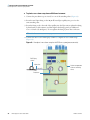
1
Thermo EASY-Spray Ion Source User Guide 60053-97260 Revision A May 2012 © 2012 Thermo Fisher Scientific Inc. All rights reserved. Acclaim, EASY-Column, EASY-nLC, EASY-Spray, Exactive, Foundation, nanoViper, PepMap, Q Exactive, Velos Pro, and Viper are trademarks, and Dionex, LCQ, LTQ, Orbitrap, Thermo Scientific, UltiMate, and Xcalibur are registered trademarks of Thermo Fisher Scientific Inc. in the United States. The following are registered trademarks in the United States and other countries: Dino-Lite is a registered trademark of AnMo Electronics Corporation. IDEX is a registered trademark of IDEX Health & Science LLC. Microsoft and Windows are registered trademarks of Microsoft Corporation. PEEK is a trademark of Victrex plc. All other trademarks are the property of Thermo Fisher Scientific Inc. and its subsidiaries. Thermo Fisher Scientific Inc. provides this document to its customers with a product purchase to use in the product operation. This document is copyright protected and any reproduction of the whole or any part of this document is strictly prohibited, except with the written authorization of Thermo Fisher Scientific Inc. The contents of this document are subject to change without notice. All technical information in this document is for reference purposes only. System configurations and specifications in this document supersede all previous information received by the purchaser. Thermo Fisher Scientific Inc. makes no representations that this document is complete, accurate or errorfree and assumes no responsibility and will not be liable for any errors, omissions, damage or loss that might result from any use of this document, even if the information in the document is followed properly. This document is not part of any sales contract between Thermo Fisher Scientific Inc. and a purchaser. This document shall in no way govern or modify any Terms and Conditions of Sale, which Terms and Conditions of Sale shall govern all conflicting information between the two documents. Release history: Revision A, May 2012 For Research Use Only. Not for use in diagnostic procedures. C Contents Preface . . . . . . . . . . . . . . . . . . . . . . . . . . . . . . . . . . . . . . . . . . . . . . . . . . . . . . . . . . . . . . xi Product Requirements . . . . . . . . . . . . . . . . . . . . . . . . . . . . . . . . . . . . . . . . . . . xii Contents of the EASY-Spray Ion Source Kit . . . . . . . . . . . . . . . . . . . . . . . . . . . xii Safety and Special Notices . . . . . . . . . . . . . . . . . . . . . . . . . . . . . . . . . . . . . . . .xiv Contacting Us . . . . . . . . . . . . . . . . . . . . . . . . . . . . . . . . . . . . . . . . . . . . . . . . . xv Thermo Scientific Chapter 1 Introduction . . . . . . . . . . . . . . . . . . . . . . . . . . . . . . . . . . . . . . . . . . . . . . . . . . . . . . . . . . .1 Advantages of Nanoelectrospray . . . . . . . . . . . . . . . . . . . . . . . . . . . . . . . . . . . . . 2 Functional Description . . . . . . . . . . . . . . . . . . . . . . . . . . . . . . . . . . . . . . . . . . . . 2 Source Housing . . . . . . . . . . . . . . . . . . . . . . . . . . . . . . . . . . . . . . . . . . . . . . . . 3 Controller PCB . . . . . . . . . . . . . . . . . . . . . . . . . . . . . . . . . . . . . . . . . . . . . . . . 4 Controller Power Supply . . . . . . . . . . . . . . . . . . . . . . . . . . . . . . . . . . . . . . . . . 5 Chapter 2 Installing the EASY-Spray Source . . . . . . . . . . . . . . . . . . . . . . . . . . . . . . . . . . . . . . . .7 Installing the Ion Source onto the Mass Spectrometer . . . . . . . . . . . . . . . . . . . . . 8 Connecting the Controller Power Supply . . . . . . . . . . . . . . . . . . . . . . . . . . . . . 10 Adjusting the Emitter Tip Position . . . . . . . . . . . . . . . . . . . . . . . . . . . . . . . . . . 11 Removing the EASY-Spray Source. . . . . . . . . . . . . . . . . . . . . . . . . . . . . . . . . . . 14 Chapter 3 Connecting the LCD Monitor and Video Camera. . . . . . . . . . . . . . . . . . . . . . . . . . .15 Connecting the Monitor and Camera . . . . . . . . . . . . . . . . . . . . . . . . . . . . . . . . 15 Adjusting the Video Picture. . . . . . . . . . . . . . . . . . . . . . . . . . . . . . . . . . . . . . . . 17 Chapter 4 Connecting the LC to the EASY-Spray Column . . . . . . . . . . . . . . . . . . . . . . . . . . . .19 Tools and Supplies . . . . . . . . . . . . . . . . . . . . . . . . . . . . . . . . . . . . . . . . . . . . . . 19 Installing the EASY-Spray Column for the First Time. . . . . . . . . . . . . . . . . . . . 21 Using the nanoViper Fitting . . . . . . . . . . . . . . . . . . . . . . . . . . . . . . . . . . . . . . . 22 Connecting the LC to the EASY-Spray Column . . . . . . . . . . . . . . . . . . . . . . . . 23 Connecting an EASY-nLC 1000 Instrument to the EASY-Spray Column . . . 23 Connecting an EASY-nLC II Instrument to the EASY-Spray Column . . . . . 26 Connecting an RSLCnano System to the EASY-Spray Column. . . . . . . . . . . 28 Chapter 5 Configuring the Mass Spectrometer for NSI Mode . . . . . . . . . . . . . . . . . . . . . . . .31 Selecting Nanospray as the Ion Source . . . . . . . . . . . . . . . . . . . . . . . . . . . . . . . 31 Configuring the nanoESI (NSI) Source Parameters . . . . . . . . . . . . . . . . . . . . . . 32 EASY-Spray Ion Source User Guide iii Contents Chapter 6 Maintenance . . . . . . . . . . . . . . . . . . . . . . . . . . . . . . . . . . . . . . . . . . . . . . . . . . . . . . . . .35 Tools and Supplies . . . . . . . . . . . . . . . . . . . . . . . . . . . . . . . . . . . . . . . . . . . . . . 35 Replacing the Controller PCB . . . . . . . . . . . . . . . . . . . . . . . . . . . . . . . . . . . . . . 36 Chapter 7 Troubleshooting. . . . . . . . . . . . . . . . . . . . . . . . . . . . . . . . . . . . . . . . . . . . . . . . . . . . . . .39 Chapter 8 Replaceable Parts. . . . . . . . . . . . . . . . . . . . . . . . . . . . . . . . . . . . . . . . . . . . . . . . . . . . .41 Spare Parts. . . . . . . . . . . . . . . . . . . . . . . . . . . . . . . . . . . . . . . . . . . . . . . . . . . . . 41 Consumables . . . . . . . . . . . . . . . . . . . . . . . . . . . . . . . . . . . . . . . . . . . . . . . . . . . 41 Glossary . . . . . . . . . . . . . . . . . . . . . . . . . . . . . . . . . . . . . . . . . . . . . . . . . . . . . . . . . . . . .43 Index . . . . . . . . . . . . . . . . . . . . . . . . . . . . . . . . . . . . . . . . . . . . . . . . . . . . . . . . . . . . . . . .45 iv EASY-Spray Ion Source User Guide Thermo Scientific F Figures Figure 1. Figure 2. Figure 3. Figure 4. Figure 5. Figure 6. Figure 7. Figure 8. Figure 9. Figure 10. Figure 11. Figure 12. Figure 13. Figure 14. Figure 15. Figure 16. Figure 17. Figure 18. Figure 19. Figure 20. Figure 21. Figure 22. Figure 23. Figure 24. Figure 25. Figure 26. Figure 27. Thermo Scientific nanoLC/MS system using the EASY-Spray ion source, camera, and monitor . . . . . . . . . . . . . . . . . . . . . . . . . . . . . . . . . . . . . . . . . . . . . . . . . . . . . 1 EASY-Spray source housing . . . . . . . . . . . . . . . . . . . . . . . . . . . . . . . . . . . . . . . . . 3 Controller PCB located on the bottom of the EASY-Spray source . . . . . . . . . . . . 4 Controller power supply assembly (shown with a European input plug) . . . . . . . 5 Ion sweep cone removed from the mass spectrometer’s spray cone . . . . . . . . . . . 8 Locking lever positions . . . . . . . . . . . . . . . . . . . . . . . . . . . . . . . . . . . . . . . . . . . . 9 Ion source housing connection . . . . . . . . . . . . . . . . . . . . . . . . . . . . . . . . . . . . . . 9 Power connection for the controller PCB . . . . . . . . . . . . . . . . . . . . . . . . . . . . . 10 Emitter positioning tool . . . . . . . . . . . . . . . . . . . . . . . . . . . . . . . . . . . . . . . . . . . 11 Gap positions in front of the mass spectrometer’s ion transfer tube . . . . . . . . . . 11 X- and z-axes position controls on the EASY-Spray source . . . . . . . . . . . . . . . . 12 Y-axis position control on the EASY-Spray source . . . . . . . . . . . . . . . . . . . . . . 13 Camera and column installed on the EASY-Spray source . . . . . . . . . . . . . . . . . . 16 EASY-Spray column . . . . . . . . . . . . . . . . . . . . . . . . . . . . . . . . . . . . . . . . . . . . . 21 nanoViper fitting . . . . . . . . . . . . . . . . . . . . . . . . . . . . . . . . . . . . . . . . . . . . . . . . 22 Recommended plumbing locations on the venting tee (nanoViper example) . . 24 Example of a one-column setup with nanoViper fittings. . . . . . . . . . . . . . . . . . 24 Example of a two-column setup with nanoViper fittings and a Viper union . . . . . . . . . . . . . . . . . . . . . . . . . . . . . . . . . . . . . . . . . . . . . . . . . . . . . . 25 LC line with sleeve, ferrule, and nut . . . . . . . . . . . . . . . . . . . . . . . . . . . . . . . . . . 26 Column Out line with smaller fitting from the ZDV adapter union . . . . . . . . . 27 Example of a two-column setup for the EASY-nLC II . . . . . . . . . . . . . . . . . . . 28 Example of a one-column setup for the RSLCnano system (direct injection) . . . . . . . . . . . . . . . . . . . . . . . . . . . . . . . . . . . . . . . . . . . . . . . . . . . 29 Example of a two-column setup for the RSLCnano system (preconcentration) . . . . . . . . . . . . . . . . . . . . . . . . . . . . . . . . . . . . . . . . . . . . 30 Tune Plus window for an NSI-configured Velos Pro (example) . . . . . . . . . . . . . 32 NSI Source dialog box . . . . . . . . . . . . . . . . . . . . . . . . . . . . . . . . . . . . . . . . . . . 33 Controller PCB removed from the EASY-Spray source. . . . . . . . . . . . . . . . . . . 36 Bottom of the EASY-Spray source without the controller PCB. . . . . . . . . . . . . 37 EASY-Spray Ion Source User Guide v Regulatory Compliance Thermo Fisher Scientific performs complete testing and evaluation of its products to ensure full compliance with applicable domestic and international regulations. When the system is delivered to you, it meets all pertinent electromagnetic compatibility (EMC) and safety standards as described in the next section or sections by product name. Changes that you make to your system may void compliance with one or more of these EMC and safety standards. Changes to your system include replacing a part or adding components, options, or peripherals not specifically authorized and qualified by Thermo Fisher Scientific. To ensure continued compliance with EMC and safety standards, replacement parts and additional components, options, and peripherals must be ordered from Thermo Fisher Scientific or one of its authorized representatives. EMC Directive 2004/108/EC EMC compliance has been evaluated by Intertek Semko AB. EN61326-1:2006 Low Voltage Safety Compliance This device complies with Low Voltage Directive 2006/95/EC and harmonized standard EN 61010-1:2001. FCC Compliance Statement THIS DEVICE COMPLIES WITH PART 15 OF THE FCC RULES. OPERATION IS SUBJECT TO THE FOLLOWING TWO CONDITIONS: (1) THIS DEVICE MAY NOT CAUSE HARMFUL INTERFERENCE, AND (2) THIS DEVICE MUST ACCEPT ANY INTERFERENCE RECEIVED, INCLUDING INTERFERENCE THAT MAY CAUSE UNDESIRED OPERATION. CAUTION Read and understand the various precautionary notes, signs, and symbols contained inside this manual pertaining to the safe use and operation of this product before using the device. Notice on the Proper Use of Thermo Scientific Instruments In compliance with international regulations: Use of this instrument in a manner not specified by Thermo Fisher Scientific could impair any protection provided by the instrument. Notice on the Susceptibility to Electromagnetic Transmissions Your instrument is designed to work in a controlled electromagnetic environment. Do not use radio frequency transmitters, such as mobile phones, in close proximity to the instrument. For manufacturing location, see the label on the instrument. WEEE Compliance This product is required to comply with the European Union’s Waste Electrical & Electronic Equipment (WEEE) Directive 2002/96/EC. It is marked with the following symbol: Thermo Fisher Scientific has contracted with one or more recycling or disposal companies in each European Union (EU) Member State, and these companies should dispose of or recycle this product. See www.thermoscientific.com/ rohsweee for further information on Thermo Fisher Scientific’s compliance with these Directives and the recyclers in your country. WEEE Konformität Dieses Produkt muss die EU Waste Electrical & Electronic Equipment (WEEE) Richtlinie 2002/96/EC erfüllen. Das Produkt ist durch folgendes Symbol gekennzeichnet: Thermo Fisher Scientific hat Vereinbarungen mit Verwertungs-/Entsorgungsfirmen in allen EU-Mitgliedsstaaten getroffen, damit dieses Produkt durch diese Firmen wiederverwertet oder entsorgt werden kann. Mehr Information über die Einhaltung dieser Anweisungen durch Thermo Fisher Scientific, über die Verwerter, und weitere Hinweise, die nützlich sind, um die Produkte zu identifizieren, die unter diese RoHS Anweisung fallen, finden sie unter www.thermoscientific.com/rohsweee. Conformité DEEE Ce produit doit être conforme à la directive européenne (2002/96/EC) des Déchets d'Equipements Electriques et Electroniques (DEEE). Il est marqué par le symbole suivant: Thermo Fisher Scientific s'est associé avec une ou plusieurs compagnies de recyclage dans chaque état membre de l’union européenne et ce produit devrait être collecté ou recyclé par celles-ci. Davantage d'informations sur la conformité de Thermo Fisher Scientific à ces directives, les recycleurs dans votre pays et les informations sur les produits Thermo Fisher Scientific qui peuvent aider la détection des substances sujettes à la directive RoHS sont disponibles sur www.thermoscientific.com/rohsweee. P Preface The EASY-Spray Ion Source User Guide describes the hardware components, and provides installation and configuration procedures for the Thermo Scientific™ EASY-Spray™ ion source. Use the EASY-Spray ion source with the following Thermo Scientific mass spectrometers (MSs) for nanoelectrospray (commonly referred to as “nanoES” or “nanospray”) analysis: • Exactive™, Q Exactive™ • Orbitrap™ Series • LTQ™ Series • TSQ Series • LCQ™ Deca XP Max For information about your specific mass spectrometer, refer to the user documentation provided with your instrument. Contents • Product Requirements • Contents of the EASY-Spray Ion Source Kit • Safety and Special Notices • Contacting Us To suggest changes to the documentation Complete a brief survey about this document by clicking the button below. If you have a printed copy of this document, fill out a reader survey online at www.surveymonkey.com/s/PQM6P62 or send an e-mail message to the Technical Publications Editor at [email protected]. Thank you in advance for your help. Thermo Scientific EASY-Spray Ion Source User Guide xi Preface Product Requirements Table 1 lists the environmental requirements for the EASY-Spray source. The requirements for the mass spectrometer supersede these requirements. Refer to the “Operating Environment” chapter in the preinstallation requirements guide for your Thermo Scientific mass spectrometer. CAUTION The EASY-Spray source must connect to a certified Thermo Scientific mass spectrometer, which supplies high voltage capable of delivering a maximum of 8 kV and 100 μA. If you connect the EASY-Spray source to another type of mass spectrometer, you might impair the protection provided by the equipment. Table 1. EASY-Spray source environmental requirements Parameter Specification Altitude Up to 2000 m (6562 ft) Humidity Maximum relative humidity 80% for temperatures up to 31 °C (88 °F), decreasing linearly to 50% relative humidity at 40 °C (104 °F) Operating environment Pollution degree 2 (indoor environment; normally only nonconductive pollution) Temperature Ambient temperature: 15–27 °C (59–81 °F) Contents of the EASY-Spray Ion Source Kit Table 2 lists the parts supplied in the EASY-Spray Ion Source Kit (P/N ES081). For a list of replaceable parts, see Chapter 8, “Replaceable Parts.” Table 2. EASY-Spray Ion Source Kit (P/N ES081) (Sheet 1 of 2) Image Actual temperature C Quantity Part number EASY-Spray source housing 1 —a EASY-Spray column, 15 cm × 3 μm ID 1 ES800 Set temperature 40 45 35 50 30 OFF xii Description 55 C 60 EASY-Spray Ion Source User Guide Heater EASY Spray Thermo Scientific Preface Table 2. EASY-Spray Ion Source Kit (P/N ES081) (Sheet 2 of 2) Image Description Quantity Controller power supply assembly: Part number 1 ES231 Dino-Lite™ digital video camera and power supply unit (not shown) 1 ES216 Monitor, power supply unit, and BNC adapter (not shown) 1 ES217 1 set ES232 • Power supply unit, 24 Vdc output (shown without the input plug) • Power adapter cable (not shown) Tools: • Emitter positioning tool • 3 mm hex key 1.5 mm hex key 1 A/B mixing/venting tee, stainless steel, with three attached ferrules and nuts Sleeves, PEEK™, 1/16 in. OD a Thermo Scientific — 1 set SC901 3 IDEX™, F-233 To order another EASY-Spray source housing, you must order the EASY-Spray Ion Source Kit (P/N ES081) EASY-Spray Ion Source User Guide xiii Preface Safety and Special Notices Make sure you follow the precautionary statements presented in this guide. The safety and other special notices appear in boxes. Safety and special notices include the following. CAUTION Highlights hazards to humans, property, or the environment. Each CAUTION notice is accompanied by an appropriate CAUTION symbol. IMPORTANT Highlights information necessary to prevent damage to software, loss of data, or invalid test results; or might contain information that is critical for optimal performance of the system. Note Highlights information of general interest. Tip Highlights helpful information that can make a task easier. Table 3 lists additional caution-specific symbols that appear in the EASY-Spray Ion Source User Guide. Table 3. Caution-specific symbols and their meanings Symbol Meaning Chemical: Hazardous chemicals might be present in the instrument. Wear gloves when handling carcinogenic, corrosive, irritant, mutagenic, or toxic chemicals. Use only approved containers and procedures for disposing of waste oil. Electric Shock: An electric shock hazard is present in the instrument. Proceed with caution. Hot Surface: Allow heated components to cool before touching or servicing the instrument. Trip Hazard: The power supply cords might present a trip hazard. Be aware of the cords’ locations and secure them in place as needed. xiv EASY-Spray Ion Source User Guide Thermo Scientific Preface Contacting Us There are several ways to contact Thermo Fisher Scientific for the information you need. To copy manuals from the Internet Go to mssupport.thermo.com, agree to the Terms and Conditions, and then click Customer Manuals in the left margin of the window. To order consumable and spare parts Go to www.proxeon.com/easyspray. For part numbers, see page 41. To contact Technical Support Phone 800-532-4752 Fax 561-688-8736 E-mail (North and South America) [email protected] (Other continents) [email protected] Web site www.proxeon.com Address Thermo Fisher Scientific Edisonvej 4 DK-5000 Odense C Find software updates and utilities to download at mssupport.thermo.com. To find local contact information for sales or service Go to www.thermoscientific.com/wps/portal/ts/contactus. –or– Use the list on the following pages. Note The country code is enclosed in square brackets [ ]. The city code or area code is enclosed in parenthesis ( ). • For countries other than the U.S., when you dial from within the specified country, dial the 0 of the city code. • For countries other than Italy, when you dial from outside the country, do not dial the 0 of the city code. Thermo Scientific EASY-Spray Ion Source User Guide xv Preface North America Finland—see Sweden, Norway, and Finland United States France 1400 North Point Pkwy #10 West Palm Beach, FL 33407 E-mail: [email protected] Phone ........................ [1] 800 532 4752 Fax............................. [1] 877 373 4006 (Also representing French-speaking North Africa, Algeria, Morocco, and Tunisia) Canada 2845 Argentia Road, Unit 4 Mississauga, Ontario, L5N 8G6 E-mail: [email protected] Phone ........................ [1] 800 530 8447 Fax............................. [1] (905) 890 9161 Europe Austria Wehlistrasse 27b A-1200 Wien E-mail: [email protected] Phone ........................ [43] (0) 1 333 50 34-0 Fax............................. [43] (0) 1 333 50 34-26 Belgium Clintonpark “Keppekouter” Ninovesteenweg 198 B-9320 ERMEBODEGEM - AALST E-mail: [email protected] Phone ........................ [32] (0) 24 82 30 30 Fax............................. [32] (0) 24 82 30 31 Denmark Fruebjergvej 3 2100 København Ø E-mail: [email protected] Phone ........................ [45] (70) 23 62 67 Fax............................. [45] (70) 23 62 63 xvi EASY-Spray Ion Source User Guide 16 Avenue du Québec Silic 765 Z.A. de Courtaboeuf F-91963 Les Ulis Cédex E-mail: [email protected] Phone......................... [33] (0) 160 92 49 50 Fax ............................. [33] (0) 160 92 48 99 Germany Im Steingrund 4-6 D-63303 Dreieich E-mail: [email protected] Phone......................... [49] (0) 6103 408 1050 Fax ............................. [49] (0) 6103 408 1213 Italy Strada Rivoltana I-20090 Rodano (Milano) E-mail: [email protected] Phone......................... Numero Verde (800) 823 162 Fax ............................. [39] (02) 9532 0225 Netherlands Takkebijsters 1 NL-4817 BL Breda E-mail: [email protected] Phone......................... [31] (0) 76 57 95 555 Fax ............................. [31] (0) 76 58 10 961 Norway—see Sweden, Norway, and Finland Spain C/Valportillo I, no22 1a Planta Edificio Caoba ES-28108 Alcobendas - Madrid E-mail: [email protected] Phone......................... [34] (914) 84 59 65 Fax ............................. [34] (914) 84 35 98 Thermo Scientific Preface Europe—continued Australasia and Asia Sweden, Norway, and Finland Australia Pyramidbacken 3 S-141 75 Kungens Kurva (Stockholm) Sweden E-mail: [email protected] Phone ........................ [46] (0) 855 64 68 20 Fax............................. [46] (0) 855 64 68 08 P.O. Box 9092 5 Caribbean Drive Scoresby, VIC 3179 E-mail: [email protected] Phone......................... [61] 39757 4300 Fax ............................. [61] 9763 1169 Switzerland Japan Neuhofstrasse 11 4153 Reinach E-mail: [email protected] Phone ........................ [41] (617) 16 77 40 Fax............................. [41] (617) 16 77 20 C-2F 3-9 Moriya-cho, Kanagawa-ku Yokohama 221-0022 E-mail: [email protected] Phone......................... [81] (45) 453 9100 Fax ............................. [81] (45) 453 9110 United Kingdom Stafford House 1 Boundary Park Boundary Way Hemel Hempstead Hertfordshire HP2 7GE E-mail: [email protected] Phone ....................... [44] (0) 870 241 1034 Fax............................. [44] (0) 144 223 3667 Thermo Scientific P.R. China 7th Floor, 7F Tower West, Younghe Plaza No. 28, Andingmen East Street Beijing 100007 E-mail: [email protected] Phone (free lines)....... 800 810 5118 ................................... 400 650 5118 Fax ............................. [86] 108 837 0548 EASY-Spray Ion Source User Guide xvii 1 Introduction The Thermo Scientific EASY-Spray ion source, shown in Figure 1, maintains excellent spray stability to ensure efficient evaporation and ionization of the liquid samples—the key to achieving the highest sensitivity at nano-flow rates. Key benefits of the EASY-Spray source are as follows: • Simple, reliable, and robust design • Effortless nano liquid chromatography (nanoLC)/MS integration • Better separation with zero dead volume (ZDV) connections • Increased productivity with the temperature-controlled EASY-Spray column™ Figure 1. nanoLC/MS system using the EASY-Spray ion source, camera, and monitor Thermo Scientific EASY-nLC series instrument Thermo Scientific mass spectrometer with the EASY-Spray ion source Contents • Advantages of Nanoelectrospray • Functional Description Thermo Scientific EASY-Spray Ion Source User Guide 1 1 Introduction Advantages of Nanoelectrospray Advantages of Nanoelectrospray The use of electrospray ionization (ESI) has evolved as a leading technique for generating intact, gas-phase ions from thermally labile, polar analytes in solution. In this technique, ionization is induced by the use of an emitter (a capillary tube or needle) at a controlled distance from a counter electrode. Direct current (dc) voltage is applied, either to the needle or to the solvent, to produce a strong electrical field at the emitter tip. The electric field excites the ions in the solution as they leave the emitter tip. This interaction results in electrohydrodynamic disintegration of the fluid, generation of droplets, and formation of an aerosol jet. Conventional ESI employs flow rates from 1 μL/min to 1 mL/min. Due to the high volume of liquid exiting the emitter, a drying gas, thermal heating, or both are often required to expedite desolvation and droplet shrinkage. A form of ESI that employs low flow rates of 10–1000 nL/min is nanoelectrospray ionization (nanoESI or NSI), which is also known as nanospray ionization (NSI). NSI (or nanoESI) generally does not require a drying gas or thermal heating. Compared with ESI, NSI tolerates a wider range of liquid compositions including pure water. As you lower the flow rate, a lower volume of mobile phase passes through the emitter, producing smaller aerosol droplets. This makes NSI more effective than conventional ESI at concentrating the analyte at the emitter tip, producing significant increases in sensitivity demonstrated by the signal response of the mass spectrometer. Note The Thermo Tune Plus application uses the terms “nanospray” and “NSI.” Functional Description This section describes the following principal components of the EASY-Spray source and their functions: • Source Housing • Controller PCB • Controller Power Supply 2 EASY-Spray Ion Source User Guide Thermo Scientific 1 Introduction Functional Description Source Housing The EASY-Spray source housing (Figure 2) arrives assembled and is easy to install on the mass spectrometer. The source housing includes two locking levers, two observation windows, a position-adjustable column holder, and a controller printed circuit board (PCB). For installation instructions, see “Installing the Ion Source onto the Mass Spectrometer” on page 8. Figure 2. EASY-Spray source housing Opening for the camera Source housing Column holder Using the top and front observation windows, you can view the tip of the emitter positioning tool while you move it into position. To enhance your view of the tool and then later of the emitter, connect the digital video camera and LCD monitor. For instructions, see Chapter 3, “Connecting the LCD Monitor and Video Camera.” The column holder is mounted onto the front observation window and includes a position control knob. Use the control knob to align the z axis (front-to-back) of the emitter positioning tool (Figure 9 on page 11) with the mass spectrometer’s ion transfer tube. To align the tool’s x-axis (side-to-side) and y-axis position (up-and-down), use the controls that are built into the EASY-Spray source housing. For instructions, see “Adjusting the Emitter Tip Position” on page 11. Thermo Scientific EASY-Spray Ion Source User Guide 3 1 Introduction Functional Description Controller PCB The EASY-Spray source contains a controller PCB (Figure 3) that powers and controls the heat generated for the connected EASY-Spray column. The controller PCB includes an input power socket, an output heater socket, a temperature control dial, and an actual temperature display. Figure 3. Controller PCB located on the bottom of the EASY-Spray source Actual temperature display Controller PCB (not visible) Input power connection The controller power supply unit connects to the input power socket, which is located on the bottom, right side of the EASY-Spray source. The cable from the EASY-Spray column connects to the heater socket, which is located on the front and labeled “Heater.” The temperature control dial has an OFF setting and temperature settings in 5 °C increments for the 30–60 °C range. As the column heats up, the actual temperature appears on the display. 4 EASY-Spray Ion Source User Guide Thermo Scientific 1 Introduction Functional Description Controller Power Supply Figure 4 shows the controller power supply assembly that consists of a wall-mounted power supply unit with a detachable input plug and a power adapter cable. The other end of the power adapter cable connects to the input power socket located on the bottom of the EASY-Spray source (Figure 3 on page 4 and Figure 8 on page 10) to provide the 24 Vdc input for the controller PCB. Figure 4. Controller power supply assembly (shown with a European input plug) Power supply unit with output cord Power adapter cable The total length of the output cord and power adapter cable is approximately 9 ft (274 cm). Make sure that there is an electrical wall outlet within reach for the power supply unit and that you provide suitable clearance around it for cooling. Thermo Scientific EASY-Spray Ion Source User Guide 5 2 Installing the EASY-Spray Source Follow these procedures to install or remove the EASY-Spray source. The only tool required is the 3 mm hex key. Note The complete EASY-Spray source installation, including the digital camera and LCD monitor, requires three electrical wall outlets. Ensure that your lab has the appropriate outlets near the nanoLC/MS system. Contents • Installing the Ion Source onto the Mass Spectrometer • Connecting the Controller Power Supply • Adjusting the Emitter Tip Position • Removing the EASY-Spray Source Thermo Scientific EASY-Spray Ion Source User Guide 7 2 Installing the EASY-Spray Source Installing the Ion Source onto the Mass Spectrometer Installing the Ion Source onto the Mass Spectrometer Before you install the EASY-Spray source, follow the procedure to prepare the mass spectrometer. To prepare the mass spectrometer 1. If installed, remove any other source from the mass spectrometer after it has cooled to room temperature. For instructions, refer to the mass spectrometer’s documentation. CAUTION HOT SURFACE Accidental contact with the part of the API probe located inside the housing can severely burn you, as this area of the probe can reach 350 °C (662 °F). In addition, although the exterior surface of the housing and the exposed part of the probe fall below the limit of 70 °C (158 °F) for accessible metal surfaces, they too pose a burn hazard. Therefore, handle ALL parts of the probe and housing with extreme caution. • Before removing the API probe and housing, allow the part to cool to room temperature (approximately 20 minutes) before you touch it. • If the mass spectrometer connects to an LC system, leave the solvent flow from the LC pump on while the probe cools to room temperature. 2. If installed, remove the optional ion sweep cone (Figure 5) from the mass spectrometer by grasping the outer ridges of the ion sweep cone and pulling it off. The spray cone is directly behind the ion sweep cone. Figure 5. Ion sweep cone removed from the mass spectrometer’s spray cone Ion sweep cone (shown is the offset orifice type for ESI, H-ESI, and APCI) 8 EASY-Spray Ion Source User Guide Spray cone Thermo Scientific 2 Installing the EASY-Spray Source Installing the Ion Source onto the Mass Spectrometer To install the EASY-Spray source onto the mass spectrometer 1. Follow the procedure “To prepare the mass spectrometer” on page 8. 2. Rotate the locking levers toward the front of the source to the unlocked position (right lever in Figure 6). Figure 6. Locking lever positions Locked position Unlocked position Top observation window 3. Align the two guide pin holes on the back of the source with the guide pins on the mass spectrometer’s ion source mount assembly (Figure 7). Note Your mass spectrometer might have a slightly different mount assembly, ion sweep cone, or both. Figure 7. Ion source housing connection High voltage (HV) connector Guide pins on the mass spectrometer’s ion source mount assembly Thermo Scientific Guide pin holes on the back of the EASY-Spray source housing EASY-Spray Ion Source User Guide 9 2 Installing the EASY-Spray Source Connecting the Controller Power Supply 4. Carefully press the source onto the mass spectrometer. 5. Rotate the locking levers 90 degrees toward the top window to the locked position (left lever in Figure 6 on page 9). The locked levers are now parallel with the front of the mass spectrometer. Connecting the Controller Power Supply CAUTION To avoid an electric shock, always use the detachable input plug provided with the power supply unit that is suitable for your country or region. To connect the controller power supply unit 1. Turn the temperature dial on the EASY-Spray source to the OFF position. 2. If not already connected, connect the detachable input plug and power adapter cable to the power supply unit (Figure 4 on page 5). 3. Plug the power supply unit into an electrical wall outlet. 4. Connect the power adapter cable to the input power socket located on the bottom, right side of the source (Figure 12 on page 13) as follows: a. Align the red dot on the plug with the red dot on the socket, which is on the right side of the socket (Figure 8). Figure 8. Power connection for the controller PCB Red dot on the socket Red dot on the plug b. Push the plug upward into the socket. CAUTION After completing the power supply connections, route the output cord so that it is not a trip hazard. 10 EASY-Spray Ion Source User Guide Thermo Scientific 2 Installing the EASY-Spray Source Adjusting the Emitter Tip Position Adjusting the Emitter Tip Position Before installing the EASY-Spray column, use the emitter positioning tool (Figure 9) and 3 mm hex key to adjust the position of the column holder. Figure 10 shows the emitter positioning tool touching the mass spectrometer’s ion transfer tube, which then correctly provides a 3 mm gap for the EASY-Spray column’s emitter. Figure 9. Emitter positioning tool Figure 10. Gap positions in front of the mass spectrometer’s ion transfer tube 0 mm gap between the ion transfer tube and the emitter positioning tool Emitter positioning tool Mass spectrometer spray cone 3 mm gap between the ion transfer tube and an actual emitter EASY-Spray column (shown without its cable) Ion transfer tube Thermo Scientific EASY-Spray Ion Source User Guide 11 2 Installing the EASY-Spray Source Adjusting the Emitter Tip Position To adjust the emitter tip position Tip To enhance your view of the emitter positioning tool’s tip, install the video camera and monitor before you begin this procedure. For instructions, see Chapter 3, “Connecting the LCD Monitor and Video Camera.” 1. Retract the z-axis (front-to-back) position by turning the control knob located on the column holder counterclockwise (Figure 11). 2. Insert the emitter positioning tool into the top of the column holder, and then slowly slide it forward until it clicks into place. 3. Align the x-axis (side-to-side) position of the emitter positioning tool to the bore of the ion transfer tube by inserting the hex key into the left-side hex socket-head screw (Figure 11). Figure 11. X- and z-axes position controls on the EASY-Spray source Inserting the emitter positioning tool Z-axis position control (knob) X-axis position control (hex socket-head screw) Y Z X 12 EASY-Spray Ion Source User Guide Thermo Scientific 2 Installing the EASY-Spray Source Adjusting the Emitter Tip Position 4. Align the y-axis (up-and-down) position of the emitter positioning tool to the bore of the ion transfer tube by inserting the hex key into the bottom hex socket-head screw (Figure 12). Figure 12. Y-axis position control on the EASY-Spray source Y-axis position control 5. Adjust the z-axis (front-to-back) position of the emitter positioning tool’s tip by turning the control knob located on the front of the column holder (Figure 11 on page 12). Move the tool’s tip so that it gently touches the bore of the ion transfer tube. IMPORTANT The fused-silica emitter is fragile. Make sure that the emitter positioning tool gently touches the ion transfer tube when you adjust its position or you will damage the actual emitter when fully inserted, requiring you to replace the EASY-Spray column. 6. After you adjust the tool tip’s position, slowly remove the emitter positioning tool. The position of the column holder is now calibrated for use with any EASY-Spray column. You must repeat this procedure if you later change the x-, y-, or z-axis position. Thermo Scientific EASY-Spray Ion Source User Guide 13 2 Installing the EASY-Spray Source Removing the EASY-Spray Source Removing the EASY-Spray Source Follow this procedure if you need to remove the EASY-Spray source from the mass spectrometer. To remove the source from the mass spectrometer 1. In the Tune Plus application, place the mass spectrometer in Standby mode. For instructions, refer to the mass spectrometer’s documentation. 2. Turn the source’s temperature dial to the OFF position. CAUTION HOT SURFACE Although below the maximum safety limit of 70 °C (158 °F), the EASY-Spray source can reach approximately 50 °C (122 °F) with the heater unit turned on, which can severely burn you. Allow the source to cool to room temperature (approximately 20 minutes) before you touch it. 3. Turn off the LC instrument. 4. Disconnect the LC plumbing from the EASY-Spray column, and then remove the EASY-Spray column. Note Do not pull on the cable from the EASY-Spray column. Use the plug to disconnect the column from the heater socket. 5. Remove the camera as follows: a. Unplug the camera power supply unit from the electrical wall outlet. b. Disconnect the camera’s yellow video connector from the back of the monitor and the black power connector from the camera power supply unit. c. Using the 1.5 mm hex key, loosen the hex socket-head screw securing the camera, and then remove the camera. 6. Unplug the controller power supply unit from the electrical wall outlet, and then disconnect the output cable from the source. 7. Rotate the locking levers 90 degrees toward the front of the source to the unlocked position (Figure 6 on page 9). 8. Grasp the source housing with both hands and slowly pull away from the mass spectrometer until it clears the guide pins. After you remove the EASY-Spray source from the mass spectrometer, place it in its original shipping box. The EASY-Spray source does not require cleaning. 14 EASY-Spray Ion Source User Guide Thermo Scientific 3 Connecting the LCD Monitor and Video Camera Follow these procedures to connect the LCD monitor and digital video camera, and to adjust the video picture. The only tool required is the 1.5 mm hex key. Contents • Connecting the Monitor and Camera • Adjusting the Video Picture Connecting the Monitor and Camera To enhance your view of the emitter tip, install the LCD monitor and digital video camera that are provided in the EASY-Spray Ion Source Kit (see Table 2 on page xii). To connect the monitor and camera 1. Follow the procedure “To install the EASY-Spray source onto the mass spectrometer” on page 9. 2. Plug the two power supply units into electrical wall outlets. 3. Install the camera as follows: a. Insert the camera into the opening above the top observation window with the focusing wheel facing toward you (Figure 13). b. Using the 1.5 mm hex key, tighten the hex socket-head screw on the left side of the top observation window (Figure 11 on page 12) until it touches the camera—do not overtighten the screw. c. Connect the camera’s black power connector to its power supply unit. Thermo Scientific EASY-Spray Ion Source User Guide 15 3 Connecting the LCD Monitor and Video Camera Connecting the Monitor and Camera Figure 13. Camera and column installed on the EASY-Spray source Camera light button Camera focusing wheel Hex socket-head screw to secure the camera 4. On the back of the monitor, make the following connections: • BNC adaptor to one of the Video IN ports • Camera’s yellow video connector to the BNC adaptor • Output cord from the other power supply unit to the DC 12V IN socket CAUTION After completing the power supply connections, route the output cords so that they are not a trip hazard. 5. Place the monitor on top of the mass spectrometer near the source by using its support arm. Make sure that the monitor is not too close to the edge. 16 EASY-Spray Ion Source User Guide Thermo Scientific 3 Connecting the LCD Monitor and Video Camera Adjusting the Video Picture Adjusting the Video Picture Use this procedure to focus the picture from the video camera. For additional information, refer to the manuals that came with the monitor and camera. To adjust the video picture 1. Follow the procedure “To connect the monitor and camera” on page 15. 2. Turn on the monitor by pressing its POWER button. The picture appears after a few seconds and is probably blurred. If there is no picture, press the monitor’s SOURCE button to change to the other video input channel. 3. If the picture is too dark, turn on the camera light by pressing its top light button (Figure 13 on page 16). 4. Adjust the picture by using the camera’s focusing wheel (Figure 13 on page 16). Thermo Scientific EASY-Spray Ion Source User Guide 17 4 Connecting the LC to the EASY-Spray Column Follow these procedures to connect the plumbing from the Thermo Scientific LC instrument to the EASY-Spray column. Contents • Tools and Supplies • Installing the EASY-Spray Column for the First Time • Using the nanoViper Fitting • Connecting the LC to the EASY-Spray Column Tools and Supplies Table 4 lists the required tools and supplies for connecting the LC plumbing configurations to the EASY-Spray column. Not all parts are required for each configuration. Note The EASY-Spray Ion Source Kit (P/N ES081) supplies the venting tee, fittings, and sleeves. You are responsible for supplying the remaining parts and tools. Table 4. Tools and supplies (Sheet 1 of 2) Image Description Part number One- and two-column setups A/B mixing/venting tee, stainless steel, SC901 with three attached ferrules and nuts Thermo Scientific Sleeves, PEEK™, 1/16 in. OD IDEX™, F-233 Wrench, open end, 1/4 in. — EASY-Spray Ion Source User Guide 19 4 Connecting the LC to the EASY-Spray Column Tools and Supplies Table 4. Tools and supplies (Sheet 2 of 2) Image Description Part number — Gloves, lint-free and powder-free Fisher Scientific: • • • • 19-120-2947A (small) 19-120-2947B (medium) 19-120-2947C (large) 19-120-2947D (X-large) Thermo Scientific: • 23827-0008 (medium) • 23827-0009 (large) Two-column setup Any nanoViper-equipped precolumn This image shows the Acclaim™ PepMap100 Nano-Trap. (For the PepMap100 Nano-Trap) Fisher Scientific, 164705 Viper™ union (for use with the EASY-nLC 1000) Thermo Scientific Dionex™, 6040.2304 ZDV adapter union (1/16 to 1/32 in.) IDEX, P-881 and plug (not shown) (for use with the EASY-nLC II) — 20 EASY-Spray Ion Source User Guide UltiMate™ 3000 RSLCnano EASY-Spray Application Kit Thermo Scientific Dionex, 6720.0395 Thermo Scientific 4 Connecting the LC to the EASY-Spray Column Installing the EASY-Spray Column for the First Time Installing the EASY-Spray Column for the First Time The EASY-Spray column (Figure 14) contains an integrated heatable column and a fused-silica emitter. For available columns, see Chapter 8, “Replaceable Parts.” IMPORTANT The EASY-Spray column assembly includes an emitter protective cover. If you push back this cover by hand, you could damage the fused-silica emitter and make the EASY-Spray column unusable. Figure 14. EASY-Spray column nanoViper fitting for the LC connection Emitter protective cover Protective cap Heater cable and plug To install the EASY-Spray column 1. Follow the procedure “To adjust the emitter tip position” on page 12. Note You can skip this step after the first time if you have not adjusted the column holder’s position. 2. Remove the protective cap on the end of the EASY-Spray column (Figure 14). 3. With the cable on the bottom, slowly push the tip of the EASY-Spray column into the column holder opening until it clicks into place. As the EASY-Spray column moves forward into the source, the protective cover over the emitter retracts to expose the emitter tip. 4. Connect the cable to the front output heater socket. Note Do not pull on the cable from the EASY-Spray column. Use the plug to connect and disconnect the column. Thermo Scientific EASY-Spray Ion Source User Guide 21 4 Connecting the LC to the EASY-Spray Column Using the nanoViper Fitting 5. Follow the appropriate procedure in “Connecting the LC to the EASY-Spray Column” on page 23. 6. Using the temperature control dial, set the temperature for the EASY-Spray column. Table 5 lists the display readings that can appear on the actual temperature display. Table 5. Readings for the actual temperature display a Display Description -- EASY-Spray column is not connected. xx. Actual temperature while heating up xx Actual temperature, stabilized BL Disconnect and reconnect power to the source.a If the display does not change, you must replace the controller PCB. See “Replacing the Controller PCB” on page 36. Using the nanoViper Fitting For some of the LC instruments, the plumbing connects to the EASY-Spray column through several nanoViper fittings, such as the one shown in Figure 15. Although these fittings can withstand ultra-high-performance LC (UHPLC) backpressures up to ~1034 bar (~15 000 psi), they are fingertight fittings, which require only very small torques to seal. Therefore, you must follow the procedure below to avoid damage by overtightening. Figure 15. nanoViper fitting PEEK sealing surface Removable knurled tightening tool Screw To use a nanoViper fitting 1. Insert the nanoViper fitting into the target port and slowly rotate the screw clockwise until you feel resistance. 2. Using the black knurled fitting tool, tighten the screw clockwise to an angle of 0–45 degrees (1/8-turn). 3. Start operating the system at the desired working pressure and check the backpressure. 22 EASY-Spray Ion Source User Guide Thermo Scientific 4 Connecting the LC to the EASY-Spray Column Connecting the LC to the EASY-Spray Column 4. If the backpressure is too low, check the system for leaks. For instructions, refer to the documentation for the LC instrument. 5. If the backpressure continues to be too low, return the system to atmospheric pressure. IMPORTANT To extend the lifetime of the nanoViper fittings, open and close the connections at only atmospheric system pressures. Opening and closing connections at high system pressures can reduce the lifetime of the fittings. 6. Tighten the screw by as much as an additional 45 degrees. Do not turn the screw beyond an angle of 90 degrees from where you felt the initial resistance. IMPORTANT To prevent damage to the sealing surface of the nanoViper fitting, do not overtighten the fitting. Connecting the LC to the EASY-Spray Column This section describes how to connect the one or two plumbing lines from a nanoLC instrument to the EASY-Spray column in either a one- or two-column configuration. Table 4 on page 19 lists the required parts. Note The EASY-nLC series instruments identify the two solvent lines as “Column Out” and “Waste In.” CAUTION Wear protective gloves when handling the solvent lines. Follow one of these procedures: • Connecting an EASY-nLC 1000 Instrument to the EASY-Spray Column • Connecting an EASY-nLC II Instrument to the EASY-Spray Column on page 26 • Connecting an RSLCnano System to the EASY-Spray Column on page 28 Connecting an EASY-nLC 1000 Instrument to the EASY-Spray Column Follow the appropriate procedure for a one- or two-column setup. The two-column setup includes a precolumn connected in the column-out flow path to the venting tee. Note Remove the nuts and ferrules from the venting tee. • To plumb a one-column setup from an EASY-nLC 1000 instrument • To plumb a two-column setup from an EASY-nLC 1000 instrument (on page 25) Thermo Scientific EASY-Spray Ion Source User Guide 23 4 Connecting the LC to the EASY-Spray Column Connecting the LC to the EASY-Spray Column To plumb a one-column setup from an EASY-nLC 1000 instrument 1. On the Column Out line, insert the nanoViper fitting into the venting tee’s side port as shown in Figure 16, tighten the fitting by hand until you feel resistance, and then tighten the fitting again by an additional 1/8- to 1/4-turn. Do not tighten the fitting by more than a 1/4-turn. Figure 16. Recommended plumbing locations on the venting tee (nanoViper example) Location for the Column Out line Location for the EASY-Spray column Location for the Waste In line CAUTION Because the fittings seal against each other inside the union, do not tighten them by more than 1/4-turn (90 degrees). Overtightening the fittings can irreparably damage their sealing surfaces. For additional information about nanoViper fittings, see “Using the nanoViper Fitting” on page 22. 2. On the Waste In line, insert the fitting into the venting tee’s bottom port, tighten the fitting by hand until you feel resistance, and then tighten the fitting by an additional 1/8- to 1/4-turn. Do not tighten the fitting by more than a 1/4-turn. 3. Connect the venting tee to the EASY-Spray column to complete the one-column setup (Figure 17). Figure 17. Example of a one-column setup with nanoViper fittings Column Out line EASY-Spray column Waste In line 24 EASY-Spray Ion Source User Guide Thermo Scientific 4 Connecting the LC to the EASY-Spray Column Connecting the LC to the EASY-Spray Column To plumb a two-column setup from an EASY-nLC 1000 instrument 1. Assemble and connect the Column Out line as follows: a. Insert the nanoViper fitting on the Column Out line into the Viper union, tighten the fitting by hand until you feel resistance, and then tighten the fitting again by an additional 1/8- to 1/4-turn (45–90 degrees). Do not tighten the fitting by more than a 1/4-turn. Note See the caution statement on page 24. b. Connect the other end of the union to the appropriate end of the nanoViper precolumn. Note Follow the recommended flow direction stated on the precolumn label. c. Insert the fitting on the other end of the precolumn into the venting tee’s side port (Figure 16 on page 24), and then tighten as noted in step 1a. 2. On the Waste In line, insert the fitting into the venting tee’s bottom port, tighten the fitting by hand until you feel resistance, and then tighten the fitting again by an additional 1/8- to 1/4-turn. Do not tighten the fitting by more than a 1/4-turn. 3. Connect the venting tee to the EASY-Spray column to complete the two-column setup (Figure 18). Figure 18. Example of a two-column setup with nanoViper fittings and a Viper union Column Out line EASY-Spray column Waste In line Tip When you install the two-column assembly, clear the One Column Setup check box in the EASY-nLC device section on the Devices page of the Maintenance menu. For instructions, refer to “Setting Up the Properties for the HPLC Device” in Chapter 4 of the EASY-nLC 1000 User Guide. When the One Column Setup check box is clear (not selected), valve W on the EASY-nLC 1000 moves to position 1–6 during the sample loading step. Excess solvent A exits the venting tee and passes through valve W to the waste beaker. Thermo Scientific EASY-Spray Ion Source User Guide 25 4 Connecting the LC to the EASY-Spray Column Connecting the LC to the EASY-Spray Column Connecting an EASY-nLC II Instrument to the EASY-Spray Column Follow the appropriate procedure for a one- or two-column setup. The two-column setup includes a precolumn connected in the column-out flow path to the venting tee. Note Remove the nuts and ferrules from the venting tee. • To plumb a one-column setup from an EASY-nLC II instrument • To plumb a two-column setup from an EASY-nLC II instrument To plumb a one-column setup from an EASY-nLC II instrument 1. Attach the nuts and ferrules to the Column Out and Waste In lines as follows: a. Insert one of the lines into a sleeve, and then slowly push it forward until the line is parallel with the end of the sleeve. b. Slide the nut and then the ferrule onto the sleeved line until the sleeve extends past the ferrule (Figure 19). c. Repeat step 1a and step 1b with the second line. Figure 19. LC line with sleeve, ferrule, and nut Nut Ferrule Sleeve 2. On the Column Out line, insert the fittings into the venting tee’s side port (Figure 16 on page 24), tighten the nut by hand until you feel resistance, and then use the 1/4 in. wrench to tighten the nut until firmly secured—do not overtighten. 3. On the Waste In line, insert the fittings into the venting tee’s bottom port, tighten the nut by hand until you feel resistance, and then use the 1/4 in. wrench to tighten the nut until firmly secured—do not overtighten. 4. Connect the venting tee to the EASY-Spray column to complete the one-column setup. Figure 17 on page 24 shows an example of a one-column setup for the EASY-nLC 1000 instrument, which uses nanoViper fittings. 26 EASY-Spray Ion Source User Guide Thermo Scientific 4 Connecting the LC to the EASY-Spray Column Connecting the LC to the EASY-Spray Column To plumb a two-column setup from an EASY-nLC II instrument 1. Assemble and connect the Column Out line as follows: a. Remove the smaller fitting from the ZDV adapter union, insert the Column Out line into the fitting, and then slowly push the line forward until it extends past the fitting (Figure 20). Figure 20. Column Out line with smaller fitting from the ZDV adapter union Smaller fitting (P/N F-126S) for the adapter union b. With the plug inserted into the ZDV adapter union’s larger end, insert the Column Out line into the union’s smaller end, and then tighten the smaller fitting until you feel resistance. c. Remove the plug from the adapter union, and then connect the adapter union’s larger end to the appropriate end of the nanoViper precolumn. Note Follow the recommended flow direction stated on the precolumn label. d. Insert the fitting at the other end of the precolumn into the venting tee’s side port (Figure 16 on page 24), and then tighten the fitting by an additional 1/8- to 1/4-turn (45–90 degrees). Do not tighten the fitting by more than a 1/4-turn. CAUTION Because the fittings seal against each other inside the union, do not tighten them by more than 1/4-turn (90 degrees). Overtightening the fittings can irreparably damage their sealing surfaces. For additional information about nanoViper fittings, see “Using the nanoViper Fitting” on page 22. 2. Assemble and connect the Waste In line as follows: a. Attach a nut and ferrule to the Waste In line. See step 1a and step 1b in “To plumb a one-column setup from an EASY-nLC II instrument” on page 26. b. Insert the nut and ferrule fittings into the venting tee’s bottom port, tighten the nut by hand until you feel resistance, and then use the 1/4 in. wrench to tighten the nut until firmly secured—do not overtighten. 3. Connect the venting tee to the EASY-Spray column to complete the two-column setup (Figure 21). Thermo Scientific EASY-Spray Ion Source User Guide 27 4 Connecting the LC to the EASY-Spray Column Connecting the LC to the EASY-Spray Column Figure 21. Example of a two-column setup for the EASY-nLC II Column Out line EASY-Spray column Waste In line Connecting an RSLCnano System to the EASY-Spray Column Follow the appropriate procedure for a one- or two-column setup. The two-column setup includes a precolumn connected across the autosampler valve. Note To connect the RSLCnano system to the EASY-Spray column, you must use the Thermo Scientific Dionex UltiMate 3000 RSLCnano EASY-Spray Application Kit (P/N 6720.0395). • To plumb a one-column setup from an RSLCnano instrument • To plumb a two-column setup from an RSLCnano instrument (on page 30) To plumb a one-column setup from an RSLCnano instrument 1. Insert the nanoViper fitting on the 20 μm ID nanoViper capillary into port 5 of the autosampler valve (Figure 22). 2. Insert the fitting on the other end of the capillary into the Viper union, tighten the fitting by hand until you feel resistance, and then tighten the fitting again by an additional 1/8- to 1/4-turn (45–90 degrees). Do not tighten the fitting by more than a 1/4-turn. CAUTION Because the fittings seal against each other inside the union, do not tighten them by more than 1/4-turn (90 degrees). Overtightening the fittings can irreparably damage their sealing surfaces. For additional information about nanoViper fittings, see “Using the nanoViper Fitting” on page 22. 28 EASY-Spray Ion Source User Guide Thermo Scientific 4 Connecting the LC to the EASY-Spray Column Connecting the LC to the EASY-Spray Column 3. Connect the union to the EASY-Spray column to complete the one-column setup (Figure 22). Figure 22. Example of a one-column setup for the RSLCnano system (direct injection) EASY-Spray column 20 μm ID × 65 cm Viper union 20 μm ID Autosampler 1 μL loop Thermo Scientific EASY-Spray Ion Source User Guide 29 4 Connecting the LC to the EASY-Spray Column Connecting the LC to the EASY-Spray Column To plumb a two-column setup from an RSLCnano instrument 1. Connect the precolumn to ports 2 and 5 on one of the switching valves (Figure 23). 2. Insert the nanoViper fitting on the 20 μm ID nanoViper capillary into port 4 on the same switching valve. 3. Insert the fitting on the other end of the capillary into the Viper union, tighten the fitting by hand until you feel resistance, and then tighten the fitting again by an additional 1/8- to 1/4-turn (45–90 degrees). Do not tighten the fitting by more than a 1/4-turn. Note See the caution statement on page 28. 4. Connect the union to the EASY-Spray column to complete the two-column setup (Figure 23). Figure 23. Example of a two-column setup for the RSLCnano system (preconcentration) EASY-Spray column Viper union 20 μm ID 20 μm ID Column compartment with two switching valves Precolumn 30 EASY-Spray Ion Source User Guide Thermo Scientific 5 Configuring the Mass Spectrometer for NSI Mode Follow the applicable procedures to configure the Thermo Scientific mass spectrometer for nanoelectrospray ionization (nanoESI or NSI) mode. Contents • Selecting Nanospray as the Ion Source • Configuring the nanoESI (NSI) Source Parameters Selecting Nanospray as the Ion Source Note This section is for the LCQ Deca XP Max mass spectrometer, which uses the Thermo Xcalibur™ data system version 2.0.7 or earlier. After you install the EASY-Spray source, use the Instrument Configuration window to configure the mass spectrometer for NSI mode. To configure the mass spectrometer for NSI mode 1. If open, close the Xcalibur data system and Tune Plus application. 2. On the Microsoft™ Windows™ taskbar, choose Start > All Programs > Xcalibur > Instrument Configuration to open the Instrument Configuration window. 3. Select the devices to control from the Xcalibur data system if not already selected: a. In the Device Types list, select All. b. Under Available Devices, double-click the icons for the mass spectrometer and nanoelectrospray LC instrument to add them to the Configured Devices list. 4. Double-click the mass spectrometer icon to open the Model Configuration dialog box. 5. In the left pane, select Ion Source to display the ion source configuration page, and then select Nanospray in the Default Source list. 6. Click OK, and then click OK again to close the message box. 7. Configure the LC device if you have not done so. For instructions, refer to the LC instrument documentation. Thermo Scientific EASY-Spray Ion Source User Guide 31 5 Configuring the Mass Spectrometer for NSI Mode Configuring the nanoESI (NSI) Source Parameters 8. In the Instrument Configuration window, click Done. 9. Restart the data system computer and the mass spectrometer. Configuring the nanoESI (NSI) Source Parameters After you complete the instrument configuration, use the Tune Plus application to configure the NSI source parameters in the NSI Source dialog box. To set the NSI source parameters 1. Do one of the following to open the Tune Plus window (Figure 24): • On the Windows taskbar, choose Start > All Programs > Thermo Instruments > model > model Tune, where model is your specific mass spectrometer. • In the Xcalibur application, click the Roadmap View icon, the Instrument Setup icon, the model MS icon, and then Tune Plus. –or– • In the Xcalibur application, click the Roadmap View icon, the Instrument Setup icon, and the model MS icon. Then, from the main toolbar choose model > Start Tune Plus. Figure 24. Tune Plus window for an NSI-configured Velos Pro (example) Icon for the NSI source 32 EASY-Spray Ion Source User Guide Thermo Scientific 5 Configuring the Mass Spectrometer for NSI Mode Configuring the nanoESI (NSI) Source Parameters 2. Click the NSI Source icon (or choose Setup > NSI Source) to open the NSI Source dialog box (Figure 25). Figure 25. NSI Source dialog box Enter the absolute value. 3. In the |Spray Voltage (kV)| box, enter 1.90. Use 1.90 kV as the start value for the spray voltage. If the intensity of the full-scan spectrum is low, gradually increase the spray voltage to improve the spectrum. The recommended range for the spray voltage is 1.40–2.40 kV. 4. Click OK. Thermo Scientific EASY-Spray Ion Source User Guide 33 6 Maintenance This chapter describes how to replace the controller PCB in the EASY-Spray source. For optimal results, follow these guidelines when performing the procedure in this chapter: • Take precautions against electrostatic discharge (ESD), especially when the lab environment is at the lower end of the relative humidity specification (see page xii). For additional guidelines, refer to the “Operating Environment” chapter in the preinstallation requirements guide for your mass spectrometer. • Proceed methodically. • Always place the components on a clean, lint-free surface. • Never overtighten a screw or use excessive force. Contents • Tools and Supplies • Replacing the Controller PCB Tools and Supplies Table 6 lists the required tools and supplies for the maintenance of the EASY-Spray source. Table 6. Tools and supplies Thermo Scientific Description Part number Controller PCB and 2.5 mm hex key ES230 EASY-Spray Ion Source User Guide 35 6 Maintenance Replacing the Controller PCB Replacing the Controller PCB If the controller PCB becomes damaged, the actual temperature display might remain off and the EASY-Spray column might not heat. Follow this procedure to install a new controller PCB. To replace the controller PCB 1. Follow the procedure “To remove the source from the mass spectrometer” on page 14. 2. Using the 2.5 mm hex key, remove the four hex socket-head screws located on the bottom of the source (Figure 12 on page 13). 3. Slowly pull out the enclosure for the controller PCB (Figure 26). IMPORTANT If you remove the controller PCB too quickly or at an angle, you might damage the PCB components or the internal heater cable routed above the controller PCB. Figure 26. Controller PCB removed from the EASY-Spray source 4. Unpack the new controller PCB and make sure it is not damaged. CAUTION To prevent damage to the electronic components on the PCB due to ESD, hold the new controller unit by the metal enclosure instead of the PCB. 36 EASY-Spray Ion Source User Guide Thermo Scientific 6 Maintenance Replacing the Controller PCB 5. Slowly push the new controller PCB enclosure into place, and route the heater cable so that it does not become damaged (pinched) (Figure 27). Figure 27. Bottom of the EASY-Spray source without the controller PCB High voltage cable connects to the column holder. Hole for the hex socket-head screw 6. Using the 2.5 mm hex key, install the four hex socket-head screws into the bottom of the controller PCB enclosure. You can now install the EASY-Spray source back onto the mass spectrometer. To dispose of the old controller PCB, see “WEEE Compliance” on page ix. Thermo Scientific EASY-Spray Ion Source User Guide 37 7 Troubleshooting Table 7 lists some EASY-Spray source and column problems, their causes, and their possible solutions. You can resolve most problems by using a new EASY-Spray column. If you need further troubleshooting assistance, contact your local Thermo Fisher Scientific field service engineer. See “Contacting Us” on page xv. Table 7. EASY-Spray source problems, causes, and solutions (Sheet 1 of 2) Problem Cause Solution The spray is unstable. There is a leak somewhere in the liquid path. Check all of the LC connections. Air bubbles in the emitter might cause the spray to “spit.” Try degassing the mobile phase or purging the line, and then recheck the line for air bubbles. The EASY-Spray column is out of alignment. Follow the procedure “Adjusting the Emitter Tip Position” on page 11. The source high-voltage (HV) connection might be unstable. Check the high voltage contact on the back of the EASY-Spray source (Figure 7 on page 9) and the front of the mass spectrometer. If the problem continues, do the following: 1. Open Tune Plus, choose View > Display Status View, and then click the All tab. 2. Choose Setup > NSI Source to open the NSI Source dialog box. 3. Compare the setting in the NSI Source dialog box to the readback value for the NSI source’s absolute spray voltage. A green check mark ( ) indicates that the parameter is functioning properly. There is an emitter blockage from particles in the sample, other small particles from the flow lines or valves, and so on. Thermo Scientific Try adjusting the spray voltage. If that does not resolve the blockage problem, insert a new EASY-Spray column. EASY-Spray Ion Source User Guide 39 7 Troubleshooting Table 7. EASY-Spray source problems, causes, and solutions (Sheet 2 of 2) Problem Cause Solution The signal intensity is weak. The parameters for the LC, MS, or both might need adjusting. Try these solutions: • Verify that the EASY-Spray column is correctly positioned (that is, clicks on insertion). • Check the LC method and MS tune method parameters. • Run a known standard to check the sensitivity. Heater issues: The column is not heated. The mass spectrometer’s spray cone and ion transfer tube are dirty. Clean both the spray cone and ion transfer tube. For instructions, refer to the mass spectrometer’s documentation. The heater is off, or there might be a loose connection or a damaged PCB. Try these solutions: • Check all of the connections for the controller power supply unit from the electrical wall outlet to the EASY-Spray source. –or– The actual temperature display is blank. 40 • Turn on the heater by selecting a temperature setting. • See “Replacing the Controller PCB” on page 36. The EASY-Spray column is damaged. EASY-Spray Ion Source User Guide Replace the EASY-Spray column. Thermo Scientific 8 Replaceable Parts This chapter lists the consumable and replaceable parts for the EASY-Spray source, and their corresponding part numbers. To order any of these parts, contact your local Thermo Fisher Scientific field service engineer or go to www.proxeon.com/easyspray. Contents • Spare Parts • Consumables Spare Parts A/B mixing/venting tee . . . . . . . . . . . . . . . . . . . . . . . . . . . . . . . . . . . . . . . . . . . . . . EASY-Spray controller PCB (with a 2.5 mm hex key) . . . . . . . . . . . . . . . . . . . . . . . EASY-Spray controller power supply with power adapter cable . . . . . . . . . . . . . . . . . EASY-Spray tools: emitter positioning tool and hex keys (1.5 mm and 3 mm) . . . . . Monitor and power supply unit . . . . . . . . . . . . . . . . . . . . . . . . . . . . . . . . . . . . . . . . Video camera and power supply unit . . . . . . . . . . . . . . . . . . . . . . . . . . . . . . . . . . . . SC901 ES230 ES231 ES232 ES217 ES216 EASY-Spray column, 15 cm × 75 μm ID, PepMap™ C18, 3 μm particles . . . . . . . . . EASY-Spray column, 15 cm × 50 μm ID, PepMap RSLC C18, 2 μm particles . . . . . EASY-Spray column, 25 cm × 75 μm ID, PepMap RSLC C18, 2 μm particles . . . . . EASY-Spray column, 50 cm × 75 μm ID, PepMap RSLC C18, 2 μm particles . . . . . ES800 ES801 ES802 ES803 Consumables Thermo Scientific EASY-Spray Ion Source User Guide 41 G Glossary A B C D E F G H I J K L M N O P Q R S T U V W X Y Z A H API ion transfer tube A tube assembly that assists in desolvating ions that are produced by the ESI, nanoESI (NSI), or APCI probe. H-ESI Heated-electrospray ionization (H-ESI), a type of atmospheric pressure ionization, converts ions in solution into ions in the gas phase by using electrospray ionization (ESI) in combination with heated auxiliary gas. atmospheric pressure chemical ionization (APCI) A soft ionization technique done in an ion source operating at atmospheric pressure. Electrons from a corona discharge initiate the process by ionizing the mobile phase vapor molecules. A reagent gas forms, which efficiently produces positive and negative ions of the analyte through a complex series of chemical reactions. atmospheric pressure ionization (API) Ionization performed at atmospheric pressure by using atmospheric pressure chemical ionization (APCI), electrospray ionization (ESI), or nanoelectrospray ionization (nanoESI or NSI). D dynamic nanoelectrospray See nanoESI nanoLC gradient separation. E electrospray ionization (ESI) A type of atmospheric pressure ionization that is currently the softest ionization technique available to transform ions in solution into ions in the gas phase. Thermo Scientific I ion source A device that converts samples to gas-phase ions. ion sweep cone A removable cone-shaped metal cover that fits on top of the API ion transfer tube and acts as a physical barrier to protect the entrance of the tube. N nano liquid chromatography (nanoLC) Liquid chromatography with typical flow rates of 10–1000 nL/min and 10–150 μm diameter columns. nanoelectrospray ionization (nanoESI or NSI) A type of electrospray ionization (ESI) that accommodates very low flow rates of sample and solvent on the order of 1–20 nL/min (for static nanoelectrospray) or 100–1000 nL/min (for dynamic nanoelectrospray, which is also called nanoESI nanoLC gradient separation). EASY-Spray Ion Source User Guide 43 Glossary: nanoESI nanoLC gradient separation nanoESI nanoLC gradient separation Employs microscale capillary columns to separate the analytes in complex mixtures. The sample is loaded onto a column using an injection valve or a gas pressure vessel. The mixture components are then eluted by a solvent gradient and pumped through the emitter. nanoESI (NSI) source The entire nanoelectrospray ion source. nanoESI (NSI) spray current The flow of charged particles in the nanoESI (NSI) source. The voltage on the NSI spray needle supplies the potential required to ionize the particles. nanoESI (NSI) spray voltage The high voltage that is applied to the spray needle in the nanoESI (NSI) source to produce the NSI spray current as liquid emerges from the nozzle. The NSI spray voltage is selected and set; the NSI spray current varies. nanospray ionization (NSI) See nanoelectrospray ionization (nanoESI or NSI). S source See ion source. static nanoelectrospray A device that performs continuous analysis of small analyte solution volumes over an extended period of time. 44 EASY-Spray Ion Source User Guide Thermo Scientific I Index C camera connecting 15 light button and focusing wheel, locations 16 removing 14 compliance FCC vii regulatory vii WEEE ix consumables 41 contacting us xv controller PCB description 4 power supply for 5 replacing 36 E EASY-Spray column assembly 21 installing 21 EASY-Spray ion source connecting controller power supply unit 10 monitor and camera 15 EASY-Spray column, installing 21 housing description 3 installing 9 kit contents xii replaceable parts 41 locking levers, positions 9 power connection 10 removing 14 x- and z-axes controls 12 y-axis control 13 electrical wall outlets 7 electromagnetic compatibility vii EMC compliance vii Thermo Scientific emitter adjusting the tip position 12 troubleshooting 39 environmental requirements xii F FCC compliance vii figures, list v G gloves, part numbers 20 H heater troubleshooting 40 high voltage connector, location 9 internal cable, location 37 troubleshooting 39 housing see EASY-Spray ion source I ion source see EASY-Spray ion source ion sweep cone 8 K kits EASY-Spray ion source xii UltiMate 3000 RSLCnano EASY-Spray Application 28 EASY-Spray Ion Source User Guide 45 Index: L L S LC connections EASY-nLC 1000, connecting to 23 EASY-nLC II, connecting to 26 RSLCnano system, connecting to 28 tools and supplies 19 locking levers, positions 9 safety standards vii signal intensity, troubleshooting 40 source see EASY-Spray ion source spray voltage readback value 39 setting the value 33 spray, troubleshooting 39 M maintenance controller PCB, replacing 36 guidelines 35 tools and supplies 35 mass spectrometer diagnostics 39 ion source, removing 14 ion sweep cone 8 NSI mode manually, LCQ Deca XP Max 31 power requirements xii preparing for the ion source 8 setting the NSI source parameters 32 monitor connecting 15 video picture, adjusting 17 T temperature control dial, settings 4 display codes 22 display location 4 tools and supplies, connecting the LC 19 troubleshooting 39 Tune Plus, opening 32 V venting tee, recommended LC connections 24 W N WEEE compliance ix nanoelectrospray, advantages of 2 nanoESI see NSI mode nanoViper fittings, using 22 NSI mode manual configuration, LCQ Deca XP Max mass spectrometer 31 setting the spray voltage 33 NSI Source dialog box 33 X x, y, and z coordinates, column holder 12 P power connection, location 4 power supply units, connecting camera 15 controller 10 monitor 15 product requirements xii R regulatory compliance vii replaceable parts 41 46 EASY-Spray Ion Source User Guide Thermo Scientific