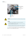
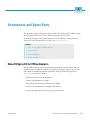
1
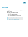
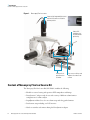
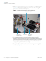
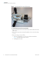
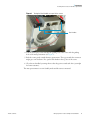
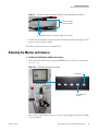
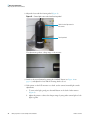
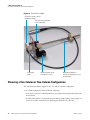
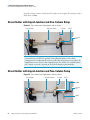
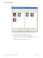
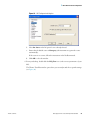
Nanospray Flex Ion
Source
Version 1.0
Getting Connected Guide
60053-97126 Revision A
November 2010
© 2010 Thermo Fisher Scientific Inc. All rights reserved.
Nanospray Flex, DirectJunction, EASY-nLC, and EASY-Column are trademarks and Xcalibur is a registered
trademark of Thermo Fisher Scientifc Inc. in the United States.
The following are registered trademarks in the United States: Nanospray is a registered trademark of AB Sciex
Pte. Ltd. Lemo is a registered trademark of Interlemo Holding S.A. Dino-Lite is a registered trademark of
Anmo Electronics Corporation. Swagelok is a registered trademark of the Crawford Fitting Company.
Thermo Fisher Scientific San Jose has a non-exclusive license with the University of Texas for US Patent
5,572,023. Caprioli: Electrospray methods and apparatus for trace analysis.
All other trademarks are the property of Thermo Fisher Scientific Inc. and its subsidiaries.
Thermo Fisher Scientific Inc. provides this document to its customers with a product purchase to use in the
product operation. This document is copyright protected and any reproduction of the whole or any part of this
document is strictly prohibited, except with the written authorization of Thermo Fisher Scientific Inc.
The contents of this document are subject to change without notice. All technical information in this
document is for reference purposes only. System configurations and specifications in this document supersede
all previous information received by the purchaser.
Thermo Fisher Scientific Inc. makes no representations that this document is complete, accurate or errorfree and assumes no responsibility and will not be liable for any errors, omissions, damage or loss that might
result from any use of this document, even if the information in the document is followed properly.
This document is not part of any sales contract between Thermo Fisher Scientific Inc. and a purchaser. This
document shall in no way govern or modify any Terms and Conditions of Sale, which Terms and Conditions of
Sale shall govern all conflicting information between the two documents.
Release history: Revision A, November 2010
Software version: EASY-nLC 2.5 and later; Xcalibur 1.3 and later
For Research Use Only. Not for use in diagnostic procedures.
Regulatory Compliance
Thermo Fisher Scientific performs complete testing and evaluation of its products to ensure full compliance with
applicable domestic and international regulations. When the system is delivered to you, it meets all pertinent
electromagnetic compatibility (EMC) and safety standards as described in the next section or sections by product name.
Changes that you make to your system may void compliance with one or more of these EMC and safety standards.
Changes to your system include replacing a part or adding components, options, or peripherals not specifically
authorized and qualified by Thermo Fisher Scientific. To ensure continued compliance with EMC and safety standards,
replacement parts and additional components, options, and peripherals must be ordered from Thermo Fisher Scientific
or one of its authorized representatives.
FCC Compliance Statement
THIS DEVICE COMPLIES WITH PART 15 OF THE FCC RULES. OPERATION IS SUBJECT TO
THE FOLLOWING TWO CONDITIONS: (1) THIS DEVICE MAY NOT CAUSE HARMFUL
INTERFERENCE, AND (2) THIS DEVICE MUST ACCEPT ANY INTERFERENCE RECEIVED,
INCLUDING INTERFERENCE THAT MAY CAUSE UNDESIRED OPERATION.
CAUTION Read and understand the various precautionary notes, signs, and symbols contained inside
this manual pertaining to the safe use and operation of this product before using the device.
Notice on the Proper Use of
Thermo Scientific Instruments
In compliance with international regulations: Use of this instrument in a manner not specified by Thermo Fisher
Scientific could impair any protection provided by the instrument.
Notice on the Susceptibility
to Electromagnetic Transmissions
Your instrument is designed to work in a controlled electromagnetic environment. Do not use radio frequency
transmitters, such as mobile phones, in close proximity to the instrument.
For manufacturing location, see the label on the instrument.
WEEE Compliance
This product is required to comply with the European Union’s Waste Electrical & Electronic Equipment (WEEE)
Directive 2002/96/EC. It is marked with the following symbol:
Thermo Fisher Scientific has contracted with one or more recycling or disposal companies in each European Union
(EU) Member State, and these companies should dispose of or recycle this product. See www.thermo.com/
WEEERoHS for further information on Thermo Fisher Scientific’s compliance with these Directives and the
recyclers in your country.
WEEE Konformität
Dieses Produkt muss die EU Waste Electrical & Electronic Equipment (WEEE) Richtlinie 2002/96/EC erfüllen.
Das Produkt ist durch folgendes Symbol gekennzeichnet:
Thermo Fisher Scientific hat Vereinbarungen mit Verwertungs-/Entsorgungsfirmen in allen EU-Mitgliedsstaaten
getroffen, damit dieses Produkt durch diese Firmen wiederverwertet oder entsorgt werden kann. Mehr Information
über die Einhaltung dieser Anweisungen durch Thermo Fisher Scientific, über die Verwerter, und weitere Hinweise,
die nützlich sind, um die Produkte zu identifizieren, die unter diese RoHS Anweisung fallen, finden sie unter
www.thermo.com/WEEERoHS.
Conformité DEEE
Ce produit doit être conforme à la directive européenne (2002/96/EC) des Déchets d'Equipements Electriques et
Electroniques (DEEE). Il est marqué par le symbole suivant:
Thermo Fisher Scientific s'est associé avec une ou plusieurs compagnies de recyclage dans chaque état membre de
l’union européenne et ce produit devrait être collecté ou recyclé par celles-ci. Davantage d'informations sur la
conformité de Thermo Fisher Scientific à ces directives, les recycleurs dans votre pays et les informations sur les
produits Thermo Fisher Scientific qui peuvent aider la détection des substances sujettes à la directive RoHS sont
disponibles sur www.thermo.com/WEEERoHS.
C
Contents
Preface . . . . . . . . . . . . . . . . . . . . . . . . . . . . . . . . . . . . . . . . . . . . . . . . . . . . . . . . . . . . . . ix
Related Documentation . . . . . . . . . . . . . . . . . . . . . . . . . . . . . . . . . . . . . . . . . . .ix
Safety and Special Notices . . . . . . . . . . . . . . . . . . . . . . . . . . . . . . . . . . . . . . . . .ix
Contacting Us . . . . . . . . . . . . . . . . . . . . . . . . . . . . . . . . . . . . . . . . . . . . . . . . . .xi
Disclaimer . . . . . . . . . . . . . . . . . . . . . . . . . . . . . . . . . . . . . . . . . . . . . . . . . . . . .xi
Declaration of Conformity . . . . . . . . . . . . . . . . . . . . . . . . . . . . . . . . . . . . . . . . xii
Thermo Scientific
Chapter 1
Introduction . . . . . . . . . . . . . . . . . . . . . . . . . . . . . . . . . . . . . . . . . . . . . . . . . . . . . . . . . . .1
Content of Nanospray Flex Ion Source Kit . . . . . . . . . . . . . . . . . . . . . . . . . . . . . 2
Unpacking the Ion Source and Preinstallation. . . . . . . . . . . . . . . . . . . . . . . . . . . 3
Installing the Ion Source on the Mass Spectrometer . . . . . . . . . . . . . . . . . . . . . . 5
Chapter 2
Electrical Connections . . . . . . . . . . . . . . . . . . . . . . . . . . . . . . . . . . . . . . . . . . . . . . . . .9
Connecting the Monitor and Cameras . . . . . . . . . . . . . . . . . . . . . . . . . . . . . . . . 9
Adjusting the Monitor and Cameras . . . . . . . . . . . . . . . . . . . . . . . . . . . . . . . . . 11
Chapter 3
DirectJunction Adaptor . . . . . . . . . . . . . . . . . . . . . . . . . . . . . . . . . . . . . . . . . . . . . . . .13
Choosing a One-Column or Two-Column Configuration . . . . . . . . . . . . . . . . 14
Choosing Stainless Steel or Glass Emitters. . . . . . . . . . . . . . . . . . . . . . . . . . . . . 15
Standard Configuration. . . . . . . . . . . . . . . . . . . . . . . . . . . . . . . . . . . . . . . . . . . 16
Assembling the Columns for Standard Configuration . . . . . . . . . . . . . . . . . . 16
Connecting the Columns to a Stainless Steel Emitter . . . . . . . . . . . . . . . . . . 17
Mounting the Column and Emitter Setup onto the DirectJunction
Adaptor . . . . . . . . . . . . . . . . . . . . . . . . . . . . . . . . . . . . . . . . . . . . . . . . . . . 18
Connecting the LC System to the Column Setup . . . . . . . . . . . . . . . . . . . . . 19
Connecting the DirectJunction to HV . . . . . . . . . . . . . . . . . . . . . . . . . . . . . 19
Chapter 4
Alternative Configurations for DirectJunction . . . . . . . . . . . . . . . . . . . . . . . . . . . .21
Stainless Steel Emitter and One-Column Setup. . . . . . . . . . . . . . . . . . . . . . . . . 21
Glass Emitter with Liquid Junction and One-Column Setup . . . . . . . . . . . . . . 22
Glass Emitter with Liquid Junction and Two-Column Setup . . . . . . . . . . . . . . 22
Packed Glass Emitter with Liquid Junction in One-Column Setup . . . . . . . . . . 23
Packed Glass Emitter with Liquid Junction in Two-Column Setup. . . . . . . . . . 24
Setup with a Long Analytical Column . . . . . . . . . . . . . . . . . . . . . . . . . . . . . . . . 25
Nanospray Flex Ion Source Getting Connected Guide
vii
Contents
Chapter 5
Nano Flex Ion Source Configuration . . . . . . . . . . . . . . . . . . . . . . . . . . . . . . . . . . . . .27
Chapter 6
Operation . . . . . . . . . . . . . . . . . . . . . . . . . . . . . . . . . . . . . . . . . . . . . . . . . . . . . . . . . . . .33
Positioning the Emitter Tip. . . . . . . . . . . . . . . . . . . . . . . . . . . . . . . . . . . . . . . . 33
Maintaining Stable Spray . . . . . . . . . . . . . . . . . . . . . . . . . . . . . . . . . . . . . . . . . 35
Using the Optional Gas Connection . . . . . . . . . . . . . . . . . . . . . . . . . . . . . . . . . 36
Appendix A Accessories and Spare Parts . . . . . . . . . . . . . . . . . . . . . . . . . . . . . . . . . . . . . . . . . . .37
Nano ES Spray Kit for Offline Analysis. . . . . . . . . . . . . . . . . . . . . . . . . . . . . . . 37
Accessories List . . . . . . . . . . . . . . . . . . . . . . . . . . . . . . . . . . . . . . . . . . . . . . . . . 38
Limited Warranty . . . . . . . . . . . . . . . . . . . . . . . . . . . . . . . . . . . . . . . . . . . . . . . 38
Additional Support . . . . . . . . . . . . . . . . . . . . . . . . . . . . . . . . . . . . . . . . . . . . . . 38
Index . . . . . . . . . . . . . . . . . . . . . . . . . . . . . . . . . . . . . . . . . . . . . . . . . . . . . . . . . . . . . . . .39
viii
Nanospray Flex Ion Source Getting Connected Guide
Thermo Scientific
P
Preface
This guide provides information on the Thermo™ Nanospray Flex™ ion source, including
setup, installation, and operation.
The Nanospray Flex ion source works in conjunction with these Thermo Scientific mass
spectrometers:
• LTQ™ Series: LTQ, Orbitrap™, FT™, Velos™
• Exactive™
• TSQ™ Series: Quantum™, Quantum Access™, Quantum Discovery MAX™, Quantum
Ultra™, Vantage™
• LCQ™ Deca XP MAX
Contents
• Related Documentation
• Safety and Special Notices
• Contacting Us
• Disclaimer
• Declaration of Conformity
Related Documentation
In addition to this guide, Thermo Fisher Scientific provides the following documents for the
Nanospray Flex ion source available as PDF files:
• Thermo Xcalibur™ manual suite
• Ion Max Source and Ion Max-S API Source Hardware Manual
The software also provides Help.
Safety and Special Notices
Make sure you follow the precautionary statements presented in this guide. The safety and
other special notices appear in boxes.
Thermo Scientific
Nanospray Flex Ion Source Getting Connected Guide
ix
Preface
Safety and special notices include the following:
CAUTION Highlights hazards to humans, property, or the environment. Each CAUTION
notice is accompanied by an appropriate CAUTION symbol.
IMPORTANT Highlights information necessary to prevent damage to software, loss of
data, or invalid test results; or might contain information that is critical for optimal
performance of the system.
Note Highlights information of general interest.
Tip Highlights helpful information that can make a task easier.
CAUTION
• Emitter tips are extremely sharp. Never touch the tips as this may cause injury.
• Always depressurize the LC-system with transfer line before removing emitters from the
source head. Failure to do so may result in the emitter being ejected at high speed.
CAUTION
• Although the ion source is shielded, in certain cases there might be access to the
emitter which is on high voltage (HV). Always turn off the HV before touching the
source head.
• Never connect a power supply able to deliver more than 8kV and 100 μA to this
Nanospray source.
• Do not leave the source unattended while the spray voltage is on.
CAUTION The interface region, especially the cone of the mass spectrometer can be hot.
Do not touch this area.
x
Nanospray Flex Ion Source Getting Connected Guide
Thermo Scientific
Preface
Contacting Us
There are several ways to contact Thermo Fisher Scientific for the information you need.
Y To contact Technical Support
Phone
800-532-4752
Fax
561-688-8736
E-mail
[email protected]
Knowledge base
www.thermokb.com
Find software updates and utilities to download at mssupport.thermo.com.
Y To contact Customer Service for ordering information
Phone
800-532-4752
Fax
561-688-8731
E-mail
[email protected]
Web site
www.thermo.com/ms
Y To get local contact information for sales or service
Go to www.thermoscientific.com/wps/portal/ts/contactus.
Y To copy manuals from the Internet
Go to mssupport.thermo.com, agree to the Terms and Conditions, and then click
Customer Manuals in the left margin of the window.
Y To suggest changes to documentation or to Help
• Fill out a reader survey online at www.surveymonkey.com/s/PQM6P62.
• Send an e-mail message to the Technical Publications Editor at
[email protected].
Disclaimer
• This equipment, including spray capillaries, is designed specifically for creating ions in a
mass spectrometer. (No other use is recommended.)
• This equipment is for laboratory use only and is not a medical device.
• This equipment must not be connected to any power supply delivering more than 8 kV
and 100 μA.
• Do not allow unauthorized or untrained operators to use this equipment.
Thermo Scientific
Nanospray Flex Ion Source Getting Connected Guide
xi
Preface
• Any misuse will be the sole responsibility of the user/owner. Thermo Fisher Scientific
assumes no implied or inferred liability for direct or consequential damages or injuries
from this instrumentation if it is operated or used in any way other than that for which it
is designed.
• Any legal disagreements must be settled before a Danish court of law.
• Only use this equipment if you agree with the conditions above.
Declaration of Conformity
European Safety Standards
Declaration of Conformity
Standard(s) to which
conformity is declared:
IEC 61010-1/ EN61010-1:2001, Second edition - “Safety
Requirements for Electrical Equipment for Measurement,
Control and Laboratory Use.”
Manufacturer’s Name:
Proxeon Biosystems A/S
Manufacturer’s Address
Edisonsvej 4, DK-5000 Odense, Denmark
Type of Equipment:
Laboratory Instrumentation
Model Name:
Nanospray Flex ion source
Model Numbers:
ES071
Serial Number:
ES-001000 and later
Year of Manufacture:
2010–
I, the undersigned hereby declare that the equipment specified above conforms to the above
Directive(s) and Standard(s).
Ole Vorm, Site Manager
xii
Nanospray Flex Ion Source Getting Connected Guide
October 11, 2010
Thermo Scientific
1
Introduction
Nanospray Flex ion sources minimize the liquid flow rate (nL/min) and maintain excellent
spray stability to ensure evaporation and ionization of liquid samples —the key to achieving
the highest sensitivity.
Key benefits of the Nanospray Flex ion source include
• User-friendly design
• Single setup for all online nanoflow applications
• Ability to interface with online nanoscale LC separation techniques
Contents
• Content of Nanospray Flex Ion Source Kit
• Unpacking the Ion Source and Preinstallation
• Installing the Ion Source on the Mass Spectrometer
Thermo Scientific
Nanospray Flex Ion Source Getting Connected Guide
1
1
Introduction
Content of Nanospray Flex Ion Source Kit
Figure 1.
Nanospray Flex ion source
Camera with integrated light source
and one LCD monitor to visualize
emitter position
Robust XYZ
manipulator for
accurate emitter
positioning
Sliding rails for
quick retraction
of emitter
Easy access to fittings and
adaptors for emitters and
columns
Content of Nanospray Flex Ion Source Kit
The Nanospray Flex Ion Source Kit (P/N ES071) includes the following:
• Flexible ion source housing with precision XYZ manipulator and fittings
• DirectJunction™ adaptor ready for use with a variety of different column/emitter
configurations for online analysis
• LiquidJunction MicroCross for one column setup with long packed emitters
• Dual camera setup including one LCD monitor
• Nanobore stainless steel emitters fitting the DirectJunction adaptor
2
Nanospray Flex Ion Source Getting Connected Guide
Thermo Scientific
1 Introduction
Unpacking the Ion Source and Preinstallation
• All necessary cables and connectors for the ion source
• Nanospray Flex Ion Source Getting Connected Guide
Unpacking the Ion Source and Preinstallation
The Nanospray source kit is packed in a single box. To fully protect the components during
transport, the source mechanics, DirectJunction adaptor, and cameras are not assembled
(see Figure 2).
Figure 2.
Nanospray ion source components
Box with
LCD monitor
DirectJunction adaptor
Screwdrivers
Stainless steel emitters
LiquidJunction
Phono-BNC
Dino-Lite
cameras
Body of
Nanospray
source
Y To unpack the ion source
1. After removing the foam from the top of the box, access the accessories for the Nanospray
source.
2. Carefully lift up the next foam bar including the accessories to access the body of the
Nanospray source.
3. Carefully take out the body of the Nanospray source and place it on a table to complete
the assembly of the Nanospray source.
Thermo Scientific
Nanospray Flex Ion Source Getting Connected Guide
3
1
Introduction
Unpacking the Ion Source and Preinstallation
4. Pull back the drawer of the Nanospray source to access the arm on the XYZ manipulator
(see Figure 3). The DirectJunction adaptor has to be mounted to this arm using the
5 mm. screw in the holder of the DirectJunction.
Figure 3.
Assembly of the DirectJunction to the XYZ manipulator arm
DirectJunction adaptor
Drawer of the
Nanospray source
5 mm screw
Arm of the XYZ
manipulator
5. Use the supplied screwdriver to mount the DirectJunction adaptor on the XYZ
manipulator arm. Before tightening the 5 mm screw, position the DirectJunction with the
back of the DirectJunction elevated about 20° above horizontal. Tighten the screw firmly.
The two white boxes in the box contain Dino-Lite™ cameras, which are located in the
opening on the top and left side of the source body.
6. Loosen the small screw which is used to secure the cameras in place with the supplied
screwdriver (see Figure 4).
4
Nanospray Flex Ion Source Getting Connected Guide
Thermo Scientific
1 Introduction
Installing the Ion Source on the Mass Spectrometer
Figure 4.
Small screw to fix
camera in place
Dino-Lite camera placed on
top of the source body
7. Remove the cameras and install the first one in the top of the source body. Note that the
camera can only be placed one way, ensuring optimal alignment. Slowly tighten the screw
until it touches the camera housing. Tighten by another half turn.
8. Repeat the procedure for the second camera, which is located on the left side of the source
body.
You are now ready to install the Nanospray source.
Installing the Ion Source on the Mass Spectrometer
After assembling the body and accessories, you are ready to mount the completed source on
the mass spectrometer.
Thermo Scientific
Nanospray Flex Ion Source Getting Connected Guide
5
1
Introduction
Installing the Ion Source on the Mass Spectrometer
Figure 5.
Thermo Nanospray Flex ion source with DirectJunction
Y To install the ion source on the mass spectrometer
1. Before removing the previous ion source, disconnect any columns and flow lines from the
HPLC system.
2. Refer to the mass spectrometer user manual for guidance on how to remove the existing
ion source.
3. Remove the existing ion source as follows:
a. Turn the two black handles on top of the source in the direction indicated in
Figure 6. The handles might give some resistance.
b. Carefully pull out the source.
6
Nanospray Flex Ion Source Getting Connected Guide
Thermo Scientific
1 Introduction
Installing the Ion Source on the Mass Spectrometer
Figure 6.
Turning the black handles on top of the ion source
Black handles
4. Take the Nanospray source and align the guiding rods of the source with the guiding
holes of the mass spectrometer (see Figure 7).
5. Push the source gently towards the mass spectrometer. The top part with the connectors
might give some resistance. If so, push a little harder in the top area of the source.
6. Close the two handles by turning them so that they point toward each other (you might
feel some resistance).
The mass spectrometer is now in Standby mode and the source is mounted.
Thermo Scientific
Nanospray Flex Ion Source Getting Connected Guide
7
1
Introduction
Installing the Ion Source on the Mass Spectrometer
Figure 7.
Guiding holes on the Nanospray source for mounting on the guiding rods of the mass
spectrometer
Multi pole connector for
the Interlock and
source recognition
HV connector
Guiding rods
8
Nanospray Flex Ion Source Getting Connected Guide
Guiding holes
Thermo Scientific
2
Electrical Connections
For correct operation, use these procedures to connect the cameras and monitor electrically
and to adjust the focus for sharp pictures.
Contents
• Connecting the Monitor and Cameras
• Adjusting the Monitor and Cameras
CAUTION When you push the XYZ manipulator onto the mounting frame of the source,
the HV for the spray emitter switches on. For your protection, always retract the drawer of
the source before working with the source head.
You must use the supplied HV cables and connectors in the Nanospray Flex ion source.
Connecting the Monitor and Cameras
After installing the Thermo Nanospray Flex ion source, you must set up the LCD monitor
and Dino-Lite cameras.
Y To connect and adjust the LCD monitor and Dino-Lite cameras
1. In the ion source kit, remove the monitor from the brown box and place it on top of the
mass spectrometer by using the support arm on the back of the monitor (see Figure 8.)
Thermo Scientific
Nanospray Flex Ion Source Getting Connected Guide
9
2
Electrical Connections
Connecting the Monitor and Cameras
Figure 8.
Back of LCD monitor
Video connectors for the
Dino-Lite cameras
BNC adaptors
Video-IN for the
cameras
12 V power supply
connector for the
LCD monitor
2. Connect the 12 V power supply connector to the monitor.
3. Locate the two BNC adaptors in the ion source kit and, using a quarter-turn, insert them
into the two Video-IN ports on the back of the monitor (Figure 8).
4. Connect the two yellow video connectors from the Dino-Lite cameras onto the two BNC
adaptors.
5. Choose and insert the appropriate connector to the power supply:
a. Locate the power supply for the cameras in the camera box.
The power supply comes equipped with an EU standard net connector. The kit box
contains one U.K. and one U.S. connector.
b. Connect the low-voltage connectors of the two power supplies to the two Dino-Lite
camera power connectors (see Figure 9).
10
Nanospray Flex Ion Source Getting Connected Guide
Thermo Scientific
2 Electrical Connections
Adjusting the Monitor and Cameras
Figure 9.
Connection of the low-voltage connectors to the camera power connectors
Dino-Lite camera
power connectors
Low-voltage connectors on the power supply for the cameras
6. Connect the power adaptors for the two Dino-Lite cameras and the power adaptor for the
monitor to your net power sockets.
The cameras and the monitor are now ready for use.
Adjusting the Monitor and Cameras
Y To adjust the LCD monitor and Dino-Lite cameras
1. Turn on the LCD monitor by pressing the POWER button on the front of the monitor
(see Figure 10).
Figure 10. LCD Monitor setup and control panel
Power button
Switch between
cameras
After a few seconds the picture from one of the two cameras appears. The picture is likely
to be very blurred.
Thermo Scientific
Nanospray Flex Ion Source Getting Connected Guide
11
2
Electrical Connections
Adjusting the Monitor and Cameras
2. Adjust the focus with the focusing wheel (Figure 4).
Figure 11. Camera light source switch and focusing wheel
Switch for the light source in
the camera
Focusing wheel
The adjustments produce a sharp image on the monitor:
3. Switch to the second camera by pressing the SOURCE button (see Figure 10 on
page 11), and adjust the focus with the focusing wheel as above.
4. If the picture on the LCD monitor is too dark, use the camera’s internal light to make
adjustments.
a. To turn on the light, gently press the small button on the back of either camera
(Figure 4).
b. Adjust the picture to achieve the sharpest image by using either camera light or both
lights together.
12
Nanospray Flex Ion Source Getting Connected Guide
Thermo Scientific
3
DirectJunction Adaptor
DirectJunction is a configurable adaptor for the Thermo Nanospray Flex ion source (see
Figure 12). It enables the flexible interchange between most online column and emitter
configurations, and uses stainless steel or glass emitters and a one-column or two-column
setup, with or without a liquid junction.
Contents
• Choosing a One-Column or Two-Column Configuration
• Choosing Stainless Steel or Glass Emitters
• Standard Configuration
• Connecting the DirectJunction to HV
Thermo Scientific
Nanospray Flex Ion Source Getting Connected Guide
13
3
DirectJunction Adaptor
Choosing a One-Column or Two-Column Configuration
Figure 12. DirectJunction adaptor
HV clamp for stainless steel or
coated glass emitters
ZDV union for connecting the
column and emitter
HV protection
shield
Mounting bracket for the
Nanospray ion source
Multipurpose adaptor for
ZDV unions, liquid junctions, and
connecting tees
Choosing a One-Column or Two-Column Configuration
The DirectJunction adaptor supports both a one- and two-column configuration.
A one-column configuration has the following advantages:
• It has fewer connections, which minimize any potential peak broadening that results from
dead volumes.
• It enables MS analysis of compounds that elute during sample loading (as they might not
bind to the column material) because the fluid path leads directly to the MS.
14
Nanospray Flex Ion Source Getting Connected Guide
Thermo Scientific
3 DirectJunction Adaptor
Choosing Stainless Steel or Glass Emitters
A two-column setup (typically a short pre/trap-column with a large inner diameter and a
longer analytical column with a narrower inner diameter) has these advantages:
• A pre/trap-column provides an increased loading capacity and an increased loading flow
rate when compared to loading directly onto the analytical column.
• It directs the loading solvent to waste so that sample “contaminants” do not enter the MS,
reducing the need to clean the MS inlet.
• A pre/trap-column acts as a guard column by protecting the analytical column from
particulate matter.
Choosing Stainless Steel or Glass Emitters
Stainless steel emitters are more robust than glass emitters, and help to maintain a stable and
consistent spray for longer periods of time.
The DirectJunction adaptor enables high voltage (HV) to be applied directly to the stainless
steel emitter through the small HV clamp at the front of the adaptor. By applying voltage
across the entire emitter, you can maintain a constant optimal electrical contact with the
liquid. The result is superior spray stability.
A cross section of scientists consider glass emitters to be more bio-inert than stainless steel
emitters. This state means reducing the risk of non-specific adsorption of biomolecules and
leads to slightly improved sensitivity. However, the degree of this adsorption depends on the
chemical characteristics of the sample.
You can pull glass emitters to produce very small ID emitter openings. However, the very
small opening at the tip often results in stability problems associated with blockage of the tip,
and means that glass emitters rarely last as long as their steel counterparts.
Glass emitters usually have HV applied through a liquid junction. This means that only a
small percentage of the bulk liquid flow is exposed to the electrode carrying the HV.
Tip When using glass emitters, do the following:
• Place the liquid junction at the high-pressure side of the column. Electrochemical
processes occurring at the electrode can otherwise create gas that leads to spray
instability.
• Use glass emitters with small ID emitter tips (<20 μm) to create back pressure in the
emitter and avoid outgassing and consequent spray instability.
Thermo Scientific
Nanospray Flex Ion Source Getting Connected Guide
15
3
DirectJunction Adaptor
Standard Configuration
Standard Configuration
Figure 13 shows the recommended configuration for the EASY-nLC™ nano-flow liquid
chromatography system and EASY-Columns™ with a stainless steel emitter installed on the
DirectJunction prior to mounting onto the Nanospray Flex ion source.
Figure 13. Configuration for the EASY-nLC and EASY-Columns on DirectJunction using a stainless
steel emitter
Stainless steel
emitter
(ES542)
EASY-Column (SC200)
10 cm, 75 μm ID,
3 μm C18 media
EASY-nLC
“Waste in” line
(1/32 in. OD)
Venting tee for two-column setup
(for 1/32 in. OD tubing)
(SC601)
EASY-Column (SC001)
2 cm, 100 μm ID,
3 μm C18 media
EASY-nLC
“Column out” line
(1/32 in. OD)
Zero-dead-volume union
(for 1/32 in. OD tubing)
(SC600)
Assembling the Columns for Standard Configuration
Y To assemble the pre-column and analytical column
1. Remove both red nuts from the ZDV union (SC600).
2. Screw the white blind plug into the union.
Figure 14. ZDV union with white blind plug (SC600)
3. Insert the pre-column (SC001) through a 2 cm (0.79 in.) 1/32 in. OD sleeve (F-385)
with arrows on the label pointing away from the sleeve.
16
Nanospray Flex Ion Source Getting Connected Guide
Thermo Scientific
3
DirectJunction Adaptor
Standard Configuration
4. Insert the sleeved pre-column through a red nut.
5. Screw in the red nut while ensuring that the pre-column and sleeve are firmly pushed
against the white blind plug.
6. Insert the other end of the pre-column through a 1/32 in. OD sleeve (F-385), ferrule, and
nut from the venting tee (SC601).
Figure 15. ZDV union (SC600) and pre-column (SC001) assembly
7. Tighten the nut while ensuring that the pre-column and sleeve are firmly pushed against
the center of the venting tee.
8. Install the analytical column on the other side of the venting tee using a 1/32 in. OD
sleeve (F385). Check the label for the flow, and firmly push the sleeve and column against
the center of the venting tee.
Figure 16. ZDV union (SC600), pre-column (SC001), venting tee (SC601), and analytical column
(SC200) assembly
Connecting the Columns to a Stainless Steel Emitter
Y To connect the columns to a stainless steel emitter
1. Remove both red nuts from a second ZDV union (SC600).
2. Insert the white blind plug into the union.
3. Insert the outlet end of the analytical column through a 1/32 in. OD sleeve (F385) and a
red nut.
4. Screw the outlet end into the union, ensuring that the column and sleeve are firmly
pushed against the white blind plug. Then, remove the white blind plug.
5. Insert the sleeved emitter (ES542) through a red nut.
Thermo Scientific
Nanospray Flex Ion Source Getting Connected Guide
17
3
DirectJunction Adaptor
Standard Configuration
6. Screw the sleeved emitter into the other end of the union, ensuring that the emitter and
sleeve are firmly pressed against the column outlet and sleeve.
Figure 17. Stainless steel emitter with 1/32 inch sleeve (ES542)
Figure 18. ZDV union assembly between analytical column and stainless steel emitter
Mounting the Column and Emitter Setup onto the DirectJunction Adaptor
Y To mount the column and emitter setup onto the DirectJunction adaptor
1. Mount the DirectJunction adaptor onto the Nanospray ion source.
2. Connect the red HV cable to the banana plug on the DirectJunction adaptor.
3. Open the front HV clamp on the DirectJunction adaptor.
4. Mount the ZDV union connecting the emitter and analytical column in the black holder
onto the DirectJunction adaptor, and close the clamp over the emitter.
5. Adjust the position of the multipurpose adaptor on the steel rod, and mount the venting
tee in the adaptor.
Figure 19. DirectJunction adaptor with two-column setup and steel emitter mounted on a
Nanospray Flex ion source
18
Nanospray Flex Ion Source Getting Connected Guide
Thermo Scientific
3
DirectJunction Adaptor
Standard Configuration
Connecting the LC System to the Column Setup
Y To connect the LC system to the column setup
1. Connect the “Column out” line from the EASY-nLC system to the pre-column through
the ZDV union, ensuring the line is firmly pushed against the pre-column and sleeve.
2. Connect the “Waste in” line from the EASY-nLC system to the third port on the
venting tee.
Figure 20. DirectJunction adaptor (as in Figure 19) but with “Column out” and “Waste in” flow
lines connected from the EASY-nLC system
Connecting the DirectJunction to HV
Make sure that the high voltage connector of the DirectJunction adaptor is inserted into the
Lemo™ HV socket on the underside of the Nanospray ion source drawer.
Figure 21.
DirectJunction adaptor
Nanospray ion source drawer
DirectJunction high voltage
connector
Thermo Scientific
Nanospray Flex Ion Source Getting Connected Guide
19
4
Alternative Configurations for DirectJunction
Depending on the specific experimental requirements on columns, emitters, and connections,
the following configurations might work well in different situations.
Contents
• Stainless Steel Emitter and One-Column Setup
• Glass Emitter with Liquid Junction and One-Column Setup
• Glass Emitter with Liquid Junction and Two-Column Setup
• Packed Glass Emitter with Liquid Junction in One-Column Setup
• Packed Glass Emitter with Liquid Junction in Two-Column Setup
• Setup with a Long Analytical Column
Stainless Steel Emitter and One-Column Setup
Figure 22. Stainless steel emitter with one column
ES542
Analytical column
To waste
SC601
Transfer
line
Note EASY-nLC software version 2.5 and later require use of the “Waste in” line
connected to the vent (SC601) upstream of the analytical column in one-column
configurations.
Thermo Scientific
Nanospray Flex Ion Source Getting Connected Guide
21
4
Alternative Configurations for DirectJunction
Glass Emitter with Liquid Junction and One-Column Setup
For earlier software versions or with other LC systems, you can replace the venting tee with a
ZDV union (SC600).
Glass Emitter with Liquid Junction and One-Column Setup
Figure 23. Glass emitter with a liquid junction and one column
Glass emitter
Analytical column
To waste
ES257
Transfer
line
Note EASY-nLC software version 2.5 and later require use of the “Waste in” line
connected to the vent (ES257) upstream of the analytical column in one-column
configurations. For earlier software versions or with other LC systems, you can replace the
Liquid Junction Cross (ES257) with a Liquid Junction Tee (ES258). Use small ID emitter
tips (<20 μm) to prevent out gassing in the tip and subsequent spray instability.
Glass Emitter with Liquid Junction and Two-Column Setup
Figure 24. Glass emitter with a liquid junction and two columns
Glass emitter
Analytical column
To waste
ES257
SC600
Transfer
line
SC001
22
Nanospray Flex Ion Source Getting Connected Guide
Thermo Scientific
4 Alternative Configurations for DirectJunction
Packed Glass Emitter with Liquid Junction in One-Column Setup
Note Use small ID emitter tips (<20 μm) to prevent out gassing in the tip and subsequent
spray instability.
Packed Glass Emitter with Liquid Junction in One-Column Setup
Figure 25. Packed glass emitter with a liquid junction and one column
Packed glass emitter
Transfer
line
To waste
ES257
Note The packed glass emitter contains the stationary phase and has dual roles: as the
analytical column and the emitter. The packed glass emitter is inserted through the ZDV
union, which only serves as positional support.
Note EASY-nLC software version 2.5 and later require use of the “Waste in” line
connected to the vent (ES257) upstream of the analytical column in one-column
configurations. In earlier software versions or with other LC systems, you can replace the
Liquid Junction Cross (ES257) with a Liquid Junction Tee (ES258).
Thermo Scientific
Nanospray Flex Ion Source Getting Connected Guide
23
4
Alternative Configurations for DirectJunction
Packed Glass Emitter with Liquid Junction in Two-Column Setup
Packed Glass Emitter with Liquid Junction in Two-Column Setup
Figure 26. Packed glass emitter with a liquid junction and two columns
Packed glass emitter
To waste
ES257
SC600
Transfer line
SC001
Note The packed glass emitter contains the stationary phase and has dual roles: as the
analytical column and the emitter. The packed glass emitter is inserted through the
ZDV union, which only serves as positional support.
24
Nanospray Flex Ion Source Getting Connected Guide
Thermo Scientific
4
Alternative Configurations for DirectJunction
Setup with a Long Analytical Column
Setup with a Long Analytical Column
Figure 27. Long analytical column
Glass emitter
Long analytical column
(>20 cm)
To waste
Transfer line
ES257
Transfer
line
Note You can easily fit long columns to the DirectJunction adaptor by coiling them
between the ZDV union and the vent (ES257). Figure 27 shows a glass emitter and a
liquid junction, but combinations with a steel emitter, a two-column configuration, or
both of these are also possible.
Note EASY-nLC software version 2.5 and later require use of the “Waste in” line
connected to the vent (ES257) upstream of the analytical column in one-column
configurations. In earlier software versions or with other LC systems, you can replace the
Liquid Junction Cross (ES257) with a Liquid Junction Tee (ES258). Use small ID emitter
tips (<20 μm) to prevent out gassing in the tip and subsequent spray instability.
Thermo Scientific
Nanospray Flex Ion Source Getting Connected Guide
25
5
Nano Flex Ion Source Configuration
When analyzing with nanospray sources, you only need to change a few mass spectrometer
settings in the Xcalibur data sytem. The MS software will automatically recognize the ion
source type.
Y To specify configuration options for the ion source
1. Open the Instrument Configuration window from the computer desktop as follows:
• For Xcalibur 2.0.7 or earlier versions, choose Start > All Programs > Xcalibur >
Instrument Configuration. Or, double-click the Instrument Configuration icon.
• For Xcalibur 2.1.0 or later versions, choose Start > All Programs > Thermo
Foundation 1.0 > Instrument Configuration.
The [Thermo Foundation] Instrument Configuration window appears with a list of the
installed available devices (see Figure 28).
Thermo Scientific
Nanospray Flex Ion Source Getting Connected Guide
27
5
Nano Flex Ion Source Configuration
Figure 28. Thermo Foundation Instrument Configuration window
2. Double-click the icon that represents your MS system (for example, LXQ MS).
A copy of the icon appears in the Configured Devices pane.
3. Complete the configuration of the mass spectrometer as follows:
a. In the Configured Devices pane, double-click the LXQ MS icon (or the icon for your
system).
The LXQ Configuration dialog box appears (see Figure 29).
28
Nanospray Flex Ion Source Getting Connected Guide
Thermo Scientific
5
Nano Flex Ion Source Configuration
Figure 29. LXQ Configuration dialog box
b. Select Ion Source in the left pane if it is not already selected.
c. Ensure that the default source is Nanospray (the instrument recognizes the source
automatically).
If the source is not correct, follow the instructions in the Xcalibur manual.
d. Click OK to close the window.
4. From your desktop, double-click the LXQ Tune icon (or the correct system name of your
MS).
The Thermo Tune Plus window opens where you can analyze and choose specific settings
(see Figure 30).
Thermo Scientific
Nanospray Flex Ion Source Getting Connected Guide
29
5
Nano Flex Ion Source Configuration
Figure 30. Thermo Tune Plus window
5. From the main menu, choose Setup > NSI Source.
The NSI source dialog box opens.
Figure 31. NSI Source dialog box
30
Nanospray Flex Ion Source Getting Connected Guide
Thermo Scientific
5
Nano Flex Ion Source Configuration
6. Set the ion spray voltage for nanospray analysis. Pay attention to these nanospray-specific
settings:
• For online analysis:
I Spray Voltage (kV): 1.40 to 2.40
(Start with 1.80 kV.)
• For offline analysis:
I Spray Voltage (kV): 0.70 to 1.20
(Start with 0.90 kV.)
7. Click OK.
Note Before you begin nanospray analysis, check that the drawer of the Nanospray Flex
ion source is pushed completely toward the frame; otherwise, a message that the source is
open appears and the MS will not scan.
The Nanospray Flex ion source is now be ready for analysis.
Thermo Scientific
Nanospray Flex Ion Source Getting Connected Guide
31
6
Operation
Both for intial setup and regular maintenance, use these procedures to monitor the position of
the emitter tip and the spray voltage/current for optimal performance.
Contents
• Positioning the Emitter Tip
• Maintaining Stable Spray
• Using the Optional Gas Connection
Positioning the Emitter Tip
The correct position of the emitter tip is an important parameter in nano ES analysis.
Y To optimize the position of the emitter tip
1. Position the spray capillary tip almost on-axis with the orifice by using the four knobs on
the XYZ manipulator (see Figure 32).
2. As you make adjustments, observe the magnified inlet/orifice on the monitor.
Thermo Scientific
Nanospray Flex Ion Source Getting Connected Guide
33
6
Operation
Positioning the Emitter Tip
Figure 32. Adjustment knobs on the XYZ manipulator
Left-right adjustment
(sideward movement of
the emitter)
Vertical adjustment of
the emitter
Adjustment toward
the orifice
Fine adjustment toward
the orifice
CAUTION Emitter tips are extremely sharp. Never touch the tips as this may cause injury.
CAUTION
• Although the ion source is shielded, there is easy access to the source head.
• Always turn off the high voltage before touching the source head. Do not leave the
source unattended while the spray voltage is on.
• Always mount the high voltage insulator correctly before turning on the high voltage.
• The interface region of the mass spectrometer can be hot. Do not touch this area.
Figure 33 illustrates some important settings whose values can vary depending on the mass
spectrometer in use. Also, the optimal distance between the emitter tip and orifice depends on
the flow rate, as does the optimal potential on the emitter.
34
Nanospray Flex Ion Source Getting Connected Guide
Thermo Scientific
6 Operation
Maintaining Stable Spray
Figure 33. Schematic setup of the ion source and the mass spectrometer interface
Sample from
HPLC system
Inlet of MS
Stainless steel or fused
silica emitter
0–20°
Optimal flow rate between
50 and 500 nL/min
A
Values for stainless steel or fused silica emitters:
A = 3 to 5 mm and the potential on the emitter, 1400 to 2400 V
Maintaining Stable Spray
For best results, use stainless steel emitters for nano electrospray experiments. These emitters
ensure straightforward initiation of the spray and help to maintain spray stability over
extended periods (up to 1000 hours).
Unstable spray is detrimental to most analyses. Table 1 lists the most common reasons for
unstable spray and ways to correct it.
Table 1. Correcting unstable electrospray
Thermo Scientific
Cause
Possible correction
The HV contact is interrupted.
Check/clean the gold contact in the HV clamp where
the emitter is held in the DirectJunction adaptor.
Check the red cable and connectors. Check if the
mass spectrometer is supplying the correct high
voltage.
Air bubbles in the emitter (if glass)
might cause the emitter to “spit.”
Check if the solvents are degassed properly.
The emitter is blocked because of
particulates in the sample, other
small particles from the flow
lines/valves, and so on.
(Stainless steel emitter only) If sonicating the emitter
does not remove the blockage, replace the emitter.
There is a leak at some point in the
liquid path.
Check if the correct flow is being delivered.
Nanospray Flex Ion Source Getting Connected Guide
35
6
Operation
Using the Optional Gas Connection
Using the Optional Gas Connection
The drawer of the Nanospray Flex ion source is equipped with a gas connector, a Swagelok™
fitting for tubing with 1/8" (OD).
Figure 34.
Swagelok 1/8” gas connector, option
for drying- or curtain gas.
In research analyses, use this optional gas connection for drying gas when you want to work in
a controlled environment around the spray area.
36
Nanospray Flex Ion Source Getting Connected Guide
Thermo Scientific
A
Accessories and Spare Parts
This appendix provides ordering information for the Nano ES Spray Kit for offline analysis,
and spare parts and accessories for the Thermo Nanospray Flex ion source.
For detailed descriptions and ordering information on the full range of spare parts and
accessories for the Nanospray Flex ion source, visit www.proxeon.com.
Contents
• Nano ES Spray Kit for Offline Analysis
• Accessories List
• Limited Warranty
• Additional Support
Nano ES Spray Kit for Offline Analysis
Through offline analysis, you can extract the maximum amount of information from very
limited amounts of sample. You can also average data extensively to improve the S/N-ratio
and conditions optimized for MS/MS experiments. Using the Nano ES Spray Kit (see
Figure 35), you can do the following:
• Work at low flow rates of 10–40 nL/min.
• Utilize nearly 100 percent of sample.
• Work effectively with sample volumes down to 300 nL.
• Avoid cross contamination by using disposable emitters.
• Spray from purely aqueous as well as purely organic solvents.
Thermo Scientific
Nanospray Flex Ion Source Getting Connected Guide
37
A
Accessories and Spare Parts
Accessories List
The Nano ES Spray Kit includes all necessary items for offline analysis. The kit is not
included with the Nanospray Flex ion source but can be ordered separately.
Figure 35. ES259 offline Nano ES Spray Kit
Accessories List
This section lists the part numbers for the followingNanospray Flex ion source accessories:
DirectJunction . . . . . . . . . . . . . . . . . . . . . . . . . . . . . . . . . . . . . . . . . . . . . . . . . . . . . . ES256
LiquidJunction with Cross 1/32 in. . . . . . . . . . . . . . . . . . . . . . . . . . . . . . . . . . . . . . . . ES257
LiquidJunction with Tee 1/32 in. . . . . . . . . . . . . . . . . . . . . . . . . . . . . . . . . . . . . . . . . ES258
Off-line source head kit. . . . . . . . . . . . . . . . . . . . . . . . . . . . . . . . . . . . . . . . . . . . . . . . ES259
One Dino-Lite video camera . . . . . . . . . . . . . . . . . . . . . . . . . . . . . . . . . . . . . . . . . . . ES216
One LCD Monitor 8 in. . . . . . . . . . . . . . . . . . . . . . . . . . . . . . . . . . . . . . . . . . . . . . . . ES217
Limited Warranty
• Thermo Fisher Scientific limits the warranty on repair of supplied Nano ES equipment
and replacement, provided that instrument operation has been in accordance with the
instructions outlined in the instruction manual.
• Abuse or misuse of the Nano ES equipment, or unauthorized repairs void this warranty.
• Limited warranty work is performed only at the factory, and the user bears the cost of
shipment to and from the factory.
• The limited warranty is as stated above and no implied or inferred liability for direct or
consequential damage is intended.
Additional Support
For further assistance, go to www.proxeon.com and click Support and Service in the left
margin of the window.
38
Nanospray Flex Ion Source Getting Connected Guide
Thermo Scientific
I
Index
A
BNC adaptor 10
emitter
glass
liquid junction, one-column setup 22
liquid junction, two-column setup 22
packed glass
liquid junction, one-column setup 23
liquid junction, two-column setup 24
stainless steel and one-column setup 21
emitter tip (caution) 34
C
F
camera
adjusting 11
Dino-Lite 9
column and emitter setup 18
column setup, long analytical 25
compliance
FCC iii
regulatory iii
WEEE v
components, ion source 3
configuring the ion source 27
FCC compliance iii
accessories 38
adaptor
See DirectJunction
analysis, offline 37
B
D
declaration of conformity xii
DirectJunction
alternative configurations 21
column and emitter setup 18
description 13
HV connection 19
mounting 4
Disclaimer xi
E
electromagnetic compatibility iii
EMC compliance iii
Thermo Scientific
G
gas connector 36
H
HV cables and connectors 9
I
installation, ion source on MS 5
instrument configuration window (Xcalibur) 27
ion source
removing existing 6
ion source - MS schematic 35
ion source kit, contents 2
M
mass spectrometers, ion source compatible ix
monitor (LCD)
adjusting 11
connecting to cameras 9
O
offline analysis 37
online/offline analysis 31
Nanospray Flex Ion Source Getting Connected Guide
39
Index: P
P
positioning, emitter tip 33
power supply and connectors 10
preinstallation, ion source 3
R
regulatory compliance iii
S
safety standards iii
spare parts 37
spray capillary 33
spray stability, maintaining 35
U
unpacking the ion source
See preinstallation, ion source
W
warranty information 38
WEEE compliance v
X
Xcalibur, settings for ion source 27
XYZ manipulator 2, 33
XYZ manipulator (caution) 9
40
Nanospray Flex Ion Source Getting Connected Guide
Thermo Scientific


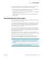


![HESI-II Probe User Guide Version B [FR]](http://vs1.manualzilla.com/store/data/006386286_1-8171fb8e5aed207e113b253f1be7db83-150x150.png)