1
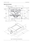
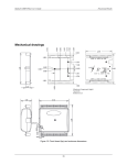
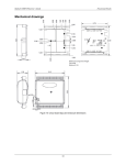
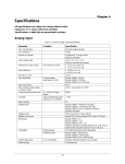
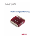
RedLab 1608FS-Plus User's Guide Functional Details For more information on digital signal connections For general information regarding digital signal connections and digital I/O techniques, refer to the Guide to Signal Connections (available on our web site at www.mccdaq.com/signals/signals.pdf). Counter input The CTR terminal is a 32-bit event counter that can accept frequency inputs up to 1 MHz. The internal counter increments when the TTL levels transition from low to high. SYNC I/O The SYNC terminal is a bidirectional I/O signal that can be configured as an input (default) or an output. Configure as an external clock input to pace the A/D conversions from an external source. The SYNC terminal supports TTL-level input signals of up to 100 kHz. Configure as an output that may be used to pace conversions on a second device and acquire data from 16 channels. Refer to page 14 for more information about synchronized operations. Trigger input The TRIG_IN terminal is an external digital trigger input. The trigger mode is software-selectable for edge or level sensitive. Edge sensitive mode is selectable for rising or falling. Level sensitive mode is selectable for high or low. Reserved The RSVD terminal is reserved for future use. Ground The analog ground (AGND) terminals provide a common ground for all analog channels. The digital ground (GND) terminals provide a common ground for the digital, trigger, counter, and sync channels and the power terminal. Power output The PC +5V output terminal can output up to 200 mA maximum. You can use this terminal to supply power to external devices or circuitry. Caution! The PC +5V terminal is an output. Do not connect it to an external power supply or you may damage the device and possibly the computer. The maximum output current that can be drawn by the RedLab 1608FS-Plus is 500 mA. This maximum applies to most personal computers and self-powered USB hubs. Bus-powered hubs and notebook computers may limit the maximum available output current to 100 mA. If the current requirement of the device exceeds the current available from the computer, connect to a self-powered hub or power the computer with an external power adapter. When running applications with the device, each DIO bit can source up to 24 mA. The total amount of current that can be sourced from the PC +5V, SYNC, and digital outputs is 200 mA max. Accuracy The overall accuracy of any instrument is limited by the error components within the system. Resolution is often used incorrectly to quantify the performance of a measurement product. While "16-bits" or "1 part in 65,536" does indicate what can be resolved, it provides little insight into the quality, or accuracy, of an absolute measurement. Accuracy specifications describe the actual measurement achievable with a RedLab 1608FSPlus. Accuracy specifications are listed Seite 16. There are three types of errors which affect the accuracy of a measurement system: offset 12 RedLab 1608FS-Plus User's Guide Functional Details gain nonlinearity The primary error sources in a RedLab 1608FS-Plus are offset and gain. Nonlinearity is small, and is not significant as an error source with respect to offset and gain. Figure 7 shows an ideal, error-free transfer function. The typical calibrated accuracy of a RedLab 1608FS-Plus is range-dependent. We use a ±10 V range as an example of what you can expect when performing a measurement in this range. Figure 7. Ideal ADC transfer function The offset error is measured at mid-scale. Ideally, a zero volt input should produce an output code of 32,768. Any deviation from this is an offset error. Figure 8 shows the transfer function with an offset error. The typical offset error specification for a RedLab 1608FS-Plus on the ±10 V range is ±1.66 mV. Offset error affects all codes equally by shifting the entire transfer function up or down along the input voltage axis. The accuracy plots in Figure 8 are drawn for clarity and are not drawn to scale. Figure 8. ADC transfer function with offset error Gain error is a change in the slope of the transfer function from the ideal, and is typically expressed as a percentage of full-scale. Figure 9 shows the RedLab 1608FS-Plustransfer function with gain error. Gain error is easily converted to voltage by multiplying the full-scale input (±10 V) by the error. 13 RedLab 1608FS-Plus User's Guide Functional Details The accuracy plots in Figure 9 are drawn for clarity and are not drawn to scale. Figure 9. ADC Transfer function with gain error For example, a RedLab 1608FS-Plus exhibits a typical calibrated gain error of ±0.04% on all ranges. For the ±10 V range, this would yield 10 V × ±0.0002 = ±4 mV. This means that at full scale, neglecting the effect of offset for the moment, the measurement would be within 4 mV of the actual value. Note that gain error is expressed as a ratio. Values near ±FS (±10 V) are more affected from an absolute voltage standpoint than are values near mid-scale, which see little or no voltage error. Combining these two error sources in Figure 10, we have a plot of the error band at ±full scale (±10 V). This plot is a graphical version of the typical accuracy specification of the product. The accuracy plots in Figure 10 are drawn for clarity and are not drawn to scale. Figure 10. Error band plot Synchronized operations You can connect the SYNC pin of multiple devices together in a master/slave configuration and acquire data from the analog inputs of all devices using one clock. When the SYNC pin is configured as an output, the internal A/D pacer clock signal is sent to the screw terminal. You can output the clock to the SYNC pin of another device that is configured for A/D pacer input. 14 RedLab 1608FS-Plus User's Guide Functional Details Mechanical drawings Figure 11. RedLab 1608FS-Plus circuit board (top) and enclosure dimensions 15 Chapter 4 Specifications All specifications are subject to change without notice. Typical for 25°C unless otherwise specified. Specifications in italic text are guaranteed by design. Analog input Table 1. General analog input specifications Parameter A/D converter type Number of channels Input configuration Sampling method Absolute maximum input voltage Input impedance Input ranges Sampling rate Throughput Condition Specification BURSTIO ≤ 32,768 total samples (uses onboard FIFO) 16-bit successive approximation type 8 single-ended Individual A/D per channel Simultaneous ±15 V max 100 MΩ min ±10 V, ±5 V, ±2 V, ±1 V 0.01 S/s to 100 kS/s, software-selectable 500 S/s all channels (400 kS/s) / (# of channels) max, 100 kS/s max for any channel (800 kS/s) / (# of channels) max, 100 kS/s max for any channel Signal DC to 25 kHz Software-selectable Software configurable. Up to eight elements – one gain element per unique, ordered channel. 16 bits 16 bits –80 dB External digital: TRIG_IN CHx IN relative to GND Software-selectable per channel Hardware paced Software paced Hardware paced (Note 1) Gain queue Resolution No missing codes Crosstalk Trigger source Note 1: Maximum throughput when scanning in hardware paced mode is machine dependent. Accuracy Analog input DC voltage measurement accuracy Table 2. Calibrated absolute accuracy Range Accuracy (mV) ±10 V ±5 V ±2 V ±1 V 5.66 2.98 1.31 0.68 16 RedLab 1608FS-Plus User's Guide Specifications Table 3. Accuracy components - All values are (±) Range Gain error (% of Reading) Gain error at FS (mV) Offset (mV) ±10 V ±5 V ±2 V ±1 V 0.04 0.04 0.04 0.04 4.00 2.00 0.80 0.40 1.66 0.98 0.51 0.28 Noise performance Table 4. Noise performance Range Typical counts LSBrms ±10 V ±5 V ±2 V ±1 V 10 10 11 14 1.52 1.52 1.67 2.12 Table 4 summarizes the noise performance for the RedLab 1608FS-Plus. Noise distribution is determined by gathering 50 K samples with inputs tied to ground at the user connector. Samples are gathered at the maximum specified sampling rate of 100 kS/s. Digital input/output Table 5. Digital I/O specifications Parameter Specification Digital type Number of I/O Configuration Pull-up/pull-down configuration 5V TTL 8 (DIO0 through DIO7) Independently configured for input or output All pins pulled up to 5V via 47 K resistors (default). May be changed to pull-down using an internal jumper. 2.0 V min Input high voltage threshold Input high voltage limit Input low voltage threshold 5.5 V absolute max 0.8 V max Input low voltage limit –0.5 V absolute min 0 V recommended min 4.4 V min (IOH = –50 µA) 3.76 V min (IOH = –24 mA) 0.1 V max (IOL = 50 µA) 0.44 V max (IOL = 24 mA) Input Output high voltage Output low voltage Power on and reset state 17 RedLab 1608FS-Plus User's Guide Specifications External trigger Table 6. External trigger specifications Parameter Condition Specification Trigger source Trigger mode External digital Software-selectable TRIG_IN Edge or level sensitive: user configurable for CMOS compatible rising or falling edge, high or low level. 2 µs + 1 pacer clock cycle max 1µs min Schmitt trigger, 47 kΩ pull-down to ground 1.01 V typ 0.6 V min 1.5 V max 2.43 V typ 1.9 V min 3.1V max 5.5 V absolute max 1.42 V typ 1.0 V min 2.0 V max -0.5 V absolute min 0 V recommended min Trigger latency Trigger pulse width Input type Schmitt trigger hysteresis Input high voltage threshold Input high voltage limit Input low voltage threshold Input low voltage limit External clock input/output Table 7. External clock I/O specifications Parameter Pin name Pin type Direction, software-selectable Input clock rate Clock pulse width Input clock mode Input type Schmitt trigger hysteresis Input high voltage threshold Input high voltage limit Input low voltage threshold Input low voltage limit Output high voltage Output low voltage Condition Input Output Input Output Specification SYNC Bidirectional Receives A/D pacer clock from external source Outputs internal A/D pacer clock 100 kHz, max 1 µs min 4 µs min Edge sensitive, rising Schmitt trigger, 47 kΩ pull-down to ground 1.01 V typ 0.6 V min 1.5 V max 2.43 V typ 1.9 V min 3.1V max 5.5 V absolute max 1.42 V typ 1.0 V min 2.0 V max -0.5 V absolute min 0 V recommended min 4.4 V min (IOH = –50 µA) 3.80 V min (IOH = –8 mA) 0.1 V max (IOL = 50 µA) 0.44 V max (IOL = 8 mA) 18 RedLab 1608FS-Plus User's Guide Specifications Counter section Table 8. Counter specifications Parameter Specification Pin name Counter type Number of channels Input type Input source Resolution Schmitt trigger hysteresis CTR Event counter 1 Schmitt trigger, 47 kΩ pull-down to ground CTR screw terminal 32 bits 1.01 V typ 0.6 V min 1.5 V max 2.43 V typ 1.9 V min 3.1V max 5.5 V absolute max 1.42 V typ 1.0 V min 2.0 V max -0.5 V absolute min 0 V recommended min 1 MHz max 500 ns min 500 ns min Input high voltage threshold Input high voltage limit Input low voltage threshold Input low voltage limit Input frequency High pulse width Low pulse width Memory Table 9. Memory specifications Parameter Specification Data FIFO EEPROM 32,768 samples, 65,536 bytes 2,048 bytes (768 bytes calibration, 256 bytes user, 1,024 bytes DAQFlex) Microcontroller Table 10. Microcontroller specifications Parameter Specification Type High performance 32-bit RISC microcontroller 19 RedLab 1608FS-Plus User's Guide Specifications Power Table 11. Power specifications Parameter Condition Specification Supply current Supply current +5V power available (Note 2) USB enumeration Including DIO and SYNC output loading Connected to externally-powered root port hub or a self-powered hub < 100 mA < 500 mA 4.5 V min, 5.25 V max Output current (Note 3) 200 mA max Note 2: "Self-powered hub" refers to a USB hub with an external power supply. Self-powered hubs allow a connected USB device to draw up to 500 mA. "Root port hubs" reside in the PC USB host Controller. The USB port(s) on your PC are root port hubs. All externally-powered root port hubs, such as a desktop PC, provide up to 500 mA of current for a USB device. Battery-powered root port hubs provide 100 mA or 500 mA, depending upon the manufacturer. A laptop PC that is not connected to an external power adapter is an example of a battery-powered root port hub. If your laptop PC is constrained to the 100 mA maximum, you need to purchase a self-powered hub. Note 3: Output current is the total amount of current that can be sourced from the PC +5V, SYNC, and digital outputs. General Table 12. General specifications Parameter Specification Device type Device compatibility USB 2.0 (full-speed) USB 1.1, USB 2.0 Environmental Table 13. Environmental specifications Parameter Specification Operating temperature range Storage temperature range Humidity 0 °C to 70 °C –40 °C to 70 °C 0% to 90% non-condensing Mechanical Table 14. Mechanical specifications Parameter Specification Dimensions (L × W × H) USB cable length User connection length 79 × 82 × 27 mm (3.10 × 3.20 × 1.05 in.) 3 m (9.84 ft) max 3 m (9.84 ft) max 20 RedLab 1608FS-Plus User's Guide Specifications Screw terminal connector and pinout Table 15. Connector specifications Parameter Specification Connector type Wire gauge range Screw terminal 16 AWG to 30 AWG Table 16. Connector pinout Pin 1 2 3 4 5 6 7 8 9 10 11 12 13 14 15 16 17 18 19 20 Signal Name CH0 IN AGND CH1 IN AGND CH2 IN AGND CH3 IN AGND CH4 IN AGND CH5 IN AGND CH6 IN AGND CH7 IN AGND RSVD AGND AGND AGND Pin 21 22 23 24 25 26 27 28 29 30 31 32 33 34 35 36 37 38 39 40 Signal Name DIO0 GND DIO1 GND DIO2 GND DIO3 GND DIO4 GND DIO5 GND DIO6 GND DIO7 SYNC TRIG_IN CTR PC +5V GND 21 Meilhaus Electronic GmbH Am Sonnenlicht 2 D-82239 Alling, Germany Phone: +49 (0)81 41 - 52 71-0 Fax: +49 (0)81 41 - 52 71-129 E-Mail: [email protected] http://www.meilhaus.com