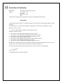
1
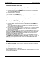
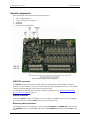
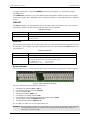
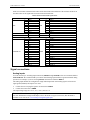
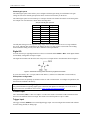
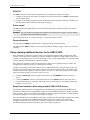
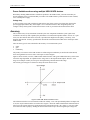
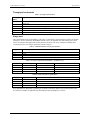
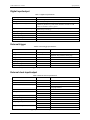
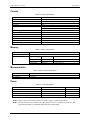
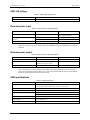
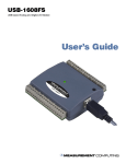
USB-1616FS Analog Input and Digital I/O User's Guide Document Revision 8 May 2012 © Copyright 2012 Your new Measurement Computing product comes with a fantastic extra — Management committed to your satisfaction! Thank you for choosing a Measurement Computing product—and congratulations! You own the finest, and you can now enjoy the protection of the most comprehensive warranties and unmatched phone tech support. It’s the embodiment of our mission: To provide data acquisition hardware and software that will save time and save money. Simple installations minimize the time between setting up your system and actually making measurements. We offer quick and simple access to outstanding live FREE technical support to help integrate MCC products into a DAQ system. Limited Lifetime Warranty: Most MCC products are covered by a limited lifetime warranty against defects in materials or workmanship for the life of the product, to the original purchaser, unless otherwise noted. Any products found to be defective in material or workmanship will be repaired, replaced with same or similar device, or refunded at MCC’s discretion. For specific information, please refer to the terms and conditions of sale. Harsh Environment Program: Any Measurement Computing product that is damaged due to misuse, or any reason, may be eligible for replacement with the same or similar device for 50% of the current list price. I/O boards face some harsh environments, some harsher than the boards are designed to withstand. Contact MCC to determine your product’s eligibility for this program. 30 Day Money-Back Guarantee: Any Measurement Computing Corporation product may be returned within 30 days of purchase for a full refund of the price paid for the product being returned. If you are not satisfied, or chose the wrong product by mistake, you do not have to keep it. These warranties are in lieu of all other warranties, expressed or implied, including any implied warranty of merchantability or fitness for a particular application. The remedies provided herein are the buyer’s sole and exclusive remedies. Neither Measurement Computing Corporation, nor its employees shall be liable for any direct or indirect, special, incidental or consequential damage arising from the use of its products, even if Measurement Computing Corporation has been notified in advance of the possibility of such damages. Trademark and Copyright Information Measurement Computing Corporation, InstaCal, Universal Library, and the Measurement Computing logo are either trademarks or registered trademarks of Measurement Computing Corporation. Refer to the Copyrights & Trademarks section on mccdaq.com/legal for more information about Measurement Computing trademarks. Other product and company names mentioned herein are trademarks or trade names of their respective companies. © 2012 Measurement Computing Corporation. All rights reserved. No part of this publication may be reproduced, stored in a retrieval system, or transmitted, in any form by any means, electronic, mechanical, by photocopying, recording, or otherwise without the prior written permission of Measurement Computing Corporation. Notice Measurement Computing Corporation does not authorize any Measurement Computing Corporation product for use in life support systems and/or devices without prior written consent from Measurement Computing Corporation. Life support devices/systems are devices or systems that, a) are intended for surgical implantation into the body, or b) support or sustain life and whose failure to perform can be reasonably expected to result in injury. Measurement Computing Corporation products are not designed with the components required, and are not subject to the testing required to ensure a level of reliability suitable for the treatment and diagnosis of people. HM USB-1616FS.docx Table of Contents Preface About this User's Guide ....................................................................................................................... 5 What you will learn from this user's guide ......................................................................................................... 5 Conventions in this user's guide ......................................................................................................................... 5 Where to find more information ......................................................................................................................... 5 Chapter 1 Introducing the USB-1616FS................................................................................................................ 6 Functional block diagram ................................................................................................................................... 7 Connecting a USB-1616FS to your computer is easy ........................................................................................ 8 Chapter 2 Installing the USB-1616FS.................................................................................................................... 9 What comes with your USB-1616FS shipment? ................................................................................................ 9 Hardware .......................................................................................................................................................................... 9 Software ............................................................................................................................................................................ 9 Documentation .................................................................................................................................................................. 9 Unpacking........................................................................................................................................................... 9 Installing the software ........................................................................................................................................ 9 Installing the hardware ....................................................................................................................................... 9 Connecting the external power supply .............................................................................................................................10 Connecting the USB-1616FS to your system...................................................................................................................10 Chapter 3 Functional Details ...............................................................................................................................12 Analog input acquisition modes ....................................................................................................................... 12 Software paced .................................................................................................................................................................12 Continuous scan ...............................................................................................................................................................12 Burst scan ........................................................................................................................................................................12 Internal components ......................................................................................................................................... 13 USB OUT connector ........................................................................................................................................................13 USB IN connector ............................................................................................................................................................13 External power connectors ...............................................................................................................................................13 USB LED .........................................................................................................................................................................14 PWR LED ........................................................................................................................................................................14 Screw terminals................................................................................................................................................................14 Signal connections ............................................................................................................................................ 15 Analog inputs ...................................................................................................................................................................15 Digital I/O ........................................................................................................................................................................16 Counter input ...................................................................................................................................................................16 Trigger input ....................................................................................................................................................................16 SYNC I/O ........................................................................................................................................................................17 Power output ....................................................................................................................................................................17 Ground terminals .............................................................................................................................................................17 Daisy chaining additional devices to the USB-1616FS .................................................................................... 17 Sample rate limitations when using multiple USB-1616FS devices ................................................................................17 Power limitations when using multiple USB-1616FS devices .........................................................................................18 Accuracy ........................................................................................................................................................... 18 Synchronized operations ................................................................................................................................... 20 Mechanical drawings ........................................................................................................................................ 21 Chapter 4 Specifications ......................................................................................................................................22 Analog input ..................................................................................................................................................... 22 3 USB-1616FS User's Guide Single board throughput ...................................................................................................................................................23 Multiple board throughput ...............................................................................................................................................23 Throughput benchmarks ..................................................................................................................................................24 Usage note .......................................................................................................................................................................24 Digital input/output........................................................................................................................................... 25 External trigger ................................................................................................................................................. 25 External clock input/output............................................................................................................................... 25 Counter ............................................................................................................................................................. 26 Memory ............................................................................................................................................................ 26 Microcontroller ................................................................................................................................................. 26 Power ................................................................................................................................................................ 26 USB +5V voltage ............................................................................................................................................. 27 External power input ........................................................................................................................................ 27 External power output ...................................................................................................................................... 27 USB specifications ........................................................................................................................................... 27 Environmental .................................................................................................................................................. 28 Mechanical ....................................................................................................................................................... 28 Screw terminals ................................................................................................................................................ 28 Declaration of Conformity ..................................................................................................................29 4 Preface About this User's Guide What you will learn from this user's guide This user's guide describes the Measurement Computing USB-1616FS data acquisition device and lists device specifications. Conventions in this user's guide For more information Text presented in a box signifies additional information and helpful hints related to the subject matter you are reading. Caution! Shaded caution statements present information to help you avoid injuring yourself and others, damaging your hardware, or losing your data. bold text Bold text is used for the names of objects on a screen, such as buttons, text boxes, and check boxes. italic text Italic text is used for the names of manuals and help topic titles, and to emphasize a word or phrase. Where to find more information Additional information about the USB-1616FS is available on our website at www.mccdaq.com. You can also contact Measurement Computing Corporation by phone, fax, or email with specific questions. Phone: 508-946-5100 and follow the instructions for reaching Tech Support Fax: 508-946-9500 to the attention of Tech Support Email: [email protected] 5 Chapter 1 Introducing the USB-1616FS The USB-1616FS is a USB 2.0 full-speed device supported under popular Microsoft® Windows® operating systems. The USB-1616FS provides true simultaneous sampling of up to sixteen 16-bit single-ended analog inputs. Simultaneous input sampling is accomplished through the use of one A/D converter per channel. The module features sampling rates of up to 50 kS/s per channel, and up to 9500 S/s per channel throughput for all channels. You can configure the analog input range of each channel independently via software. An onboard temperature sensor lets you monitor your environment temperature. Eight digital IO lines are independently selectable as input or output. A 32-bit counter can count TTL pulses. A SYNC (synchronization) control line lets you synchronize two USB-1616FS modules to acquire data synchronously from 32 analog inputs. The USB-1616FS is powered by an external +9 V unregulated power supply that is shipped with the board. Power and USB connectors let you power and control multiple MCC USB Series products from one external power source and one USB port in a daisy chain fashion. The USB-1616FS is enclosed in a rugged housing that you can mount on a DIN rail or on a bench (see Figure 1). Figure 1. USB-1616FS 6 USB-1616FS User's Guide Introducing the USB-1616FS Functional block diagram USB-1616FS functions are illustrated in the block diagram shown here. Figure 2. USB-1616FS functional block diagram 7 USB-1616FS User's Guide Introducing the USB-1616FS Connecting a USB-1616FS to your computer is easy Installing a data acquisition device has never been easier. The USB-1616FS relies upon the Microsoft Human Interface Device (HID) class drivers. The HID class drivers ship with every copy of Windows that is designed to work with USB ports. We use the Microsoft HID because it is a standard, and its performance delivers full control and maximizes data transfer rates for your USB-1616FS. No third-party device driver is required. The USB-1616FS is plug-and-play. There are no jumpers to position, DIP switches to set, or interrupts to configure. You can connect the USB-1616FS before or after you install the software, and without powering down your computer first. When you connect an HID to your system, your computer automatically detects it and configures the necessary software. You can connect and power multiple HID peripherals to your system using a USB hub. You can connect up to four USB-1616FS devices to one USB 2.0 port. You can connect up to two devices to a USB 1.1 port. You can connect your system to various devices using a standard four-wire cable. The USB connector improves upon serial and parallel port connectors with one standardized plug and port combination. Data can flow two ways between a computer and peripheral over USB connections. 8 Chapter 2 Installing the USB-1616FS What comes with your USB-1616FS shipment? The following items are shipped with the USB-1616FS. Hardware USB-1616FS USB cable (24 AWG VBUS/GND, 2 meter length) External power supply and cord (CB-PWR-9V3A) – 9 volt, 3 amp DC power supply Software MCC DAQ CD Documentation In addition to this hardware user's guide, you should also receive the Quick Start Guide. This booklet provides an overview of the MCC DAQ software you received with the device, and includes information about installing the software. Please read this booklet completely before installing any software or hardware. Unpacking As with any electronic device, you should take care while handling to avoid damage from static electricity. Before removing the USB-1616FS from its packaging, ground yourself using a wrist strap or by simply touching the computer chassis or other grounded object to eliminate any stored static charge. If your USB-1616FS arrives already damaged, notify Measurement Computing Corporation immediately by phone, fax, or email. For international customers, contact your local distributor where you purchased the USB1616FS. Phone: 508-946-5100 and follow the instructions for reaching Tech Support Fax: 508-946-9500 to the attention of Tech Support Email: [email protected] Installing the software Refer to the Quick Start Guide for instructions on installing the software on the MCC DAQ CD. This booklet is available in PDF at www.mccdaq.com/PDFmanuals/DAQ-Software-Quick-Start.pdf. Installing the hardware Before you connect the USB-1616FS to your computer, connect the external power supply that was shipped with the device. You can connect up to four MCC USB Series devices in a daisy chain configuration to a single USB 2.0 port on your computer. If your system has a USB 1.1 port, you can connect up to two MCC USB Series devices. 9 USB-1616FS User's Guide Installing the USB-1616FS Connecting the external power supply Power to the USB-1616FS is provided with the +9 V external power supply (CB-PWR-9V3A). You must connect the external power supply before connecting the USB cable to the USB-1616FS and your computer. Complete the following steps to connect the power supply to the USB-1616FS: 1. Connect the external power cord to the POWER IN connector on the rear of the USB-1616FS enclosure. This connector is labeled IN on the board. 2. Plug the power supply into a power outlet. The PWR LED is on (green) when +9 V power is supplied to the USB-1616FS. If the voltage supply is less than +6.0 V or more than +12.5 V, the PWR LED is off. Do not connect external power to the POWER OUT connector The power connector labeled POWER OUT on the enclosure (OUT on the board) provides power to an additional MCC USB Series product. If you connect the external power supply to the POWER OUT connector, the USB-1616FS does not receive power, and the PWR LED does not turn on. Connecting the USB-1616FS to your system To connect the USB-1616FS to your system, do the following. 1. Connect the USB cable that was shipped with the device to the USB connector labeled USB IN on the USB-1616FS. The USB cable supplied with the USB-1616FS has a higher gauge wire than generic USB cables, and is required for proper enumeration of the USB-1616FS. 2. Connect the other end of the USB cable to a USB port on your computer or to an external USB hub that is connected to your computer. The PWR LED turns on (green). The USB cable provides power and communication to the USB-1616FS. The USB-1616FS installs as a composite device with separate devices attached. When you connect the device for the first time, a Found New Hardware dialog opens as each device interface is detected. This is normal. After the device is installed its LED will blink and then remain on. This indicates that communication is established between the USB-1616FS and your computer. If you are running Windows XP and connect the device to a USB 1.1 port, a balloon displays the message "Your USB device can perform faster if you connect to a USB 2.0 port." You can ignore this message. The USB-1616FS functions properly when connected to a USB 1.1 port, although USB bandwidth is limited. If the USB LED turns off If communication is lost between the device and the computer, the USB LED turns off. Disconnect the USB cable from the computer and then reconnect it. This should restore communication, and the USB LED should turn on. If your system does not detect the USB-1616FS If a "USB device not recognized" message appears when you connect the USB-1616FS, do the following. 1. Unplug the USB cable from the USB-1616FS. 2. Unplug the external power cord from the POWER IN connector on the enclosure. 3. Plug the external power cord back into the POWER IN connector. 4. Plug the USB cable back into the USB-1616FS. Your system should now properly detect the USB-1616FS hardware. Contact technical support if your system still does not detect the USB-1616FS. 10 USB-1616FS User's Guide Installing the USB-1616FS Removing USB-1616FS boards from Windows XP systems Device Manager may require up to 30 seconds to detect the removal of a USB-1616FS board from a Windows XP system with Service Pack 1 or Service Pack 2 installed. This time increases with each additional connected board. If you remove four boards from your system, the time required for Device Manager to update may be almost two minutes. If you re-attach the USB-1616FS to your system before Device Manager updates, the USB LED will not turn on. Your system will not detect new hardware until Device Manager first detects that hardware has been removed. The InstaCal software will be unresponsive during this re-detection time. Wait until Device Manager updates with the new hardware before running InstaCal. The USB-1616FS is detected by the system when the device LED is on. 11 Chapter 3 Functional Details Analog input acquisition modes The USB-1616FS can acquire analog input data in three basic modes – software paced, continuous scan, and burst scan. Software paced With software paced mode you acquire one analog sample at a time. You initiate the A/D conversion by calling a software command. The analog value is converted to digital data and returned to the computer. Repeat this procedure until you have the total number of samples that you want from one channel. The maximum throughput sample rate in software paced mode is about 250 S/s, but may vary depending on your system. You may receive OVERRUN errors at higher rates on some platforms. Using the burst scan mode (BURSTIO) should resolve these problems. Continuous scan With hardware paced mode you acquire data from up to 16 channels simultaneously. The analog data is continuously acquired, converted to digital values, and written to an on-board FIFO buffer on the USB-1616FS until you stop the scan. The FIFO buffer is serviced in blocks as the data is transferred from the device FIFO buffer to the memory buffer on your computer. You can acquire data with the USB-1616FS from one channel at 50 kS/s and up to 16 channels at 9.5 kS/s each. The throughput rates for 1 to 16 channels are listed in the Specifications section on page 23. You can start a continuous scan with either a software command or with an external hardware trigger event. Burst scan With burst scan mode (BURSTIO), you can acquire data using the full capacity of its 32 k sample FIFO on the device. The acquired data is then read from the FIFO and transferred to a user memory buffer on the computer. You can initiate a single acquisition sequence for any number of input channels by either a software command or an external hardware trigger. Burst scans are limited to the depth of the on-board memory, as the data is acquired at a rate faster than it can be transferred to the computer. The maximum sampling rate is an aggregate rate, where the total acquisition rate for all channels is 200 kS/s divided by the number of channels. The maximum rate for each channel is 50 kS/s. The maximum rate that you can acquire data using burst scan mode is 50 kS/s per channel for one, two, or four channels, and 12.5 kS/s per channel for 16 channels. 12 USB-1616FS User's Guide Functional Details Internal components Major components on the USB-1616FS are shown in Figure 3. Two (2) USB connectors Two (2) external power connectors USB LED PWR LED Four (4) Screw terminal banks Figure 3. USB-1616FS internal components USB OUT connector The USB OUT connector is a downstream hub output port intended for use with other MCC USB Series products only. The USB hub is self-powered, and can provide 100 mA maximum current at 5 V. The USB out connector is labeled USB OUT on the enclosure and on the board. For information on daisy chaining to other MCC USB Series products, refer to Daisy chaining additional devices to the USB-1616FS on page 17. USB IN connector Connect the USB IN connector to the USB port on your computer (or USB hub connected to your computer). The USB in connector is labeled USB IN on the enclosure and on the board. External power connectors The USB-1616FS has two external power connectors labeled POWER IN and POWER OUT on the enclosure. The POWER IN connector is labeled IN on the board, and the POWER OUT connector is labeled OUT on the board. 13 USB-1616FS User's Guide Functional Details To supply external power, connect the POWER IN connector to the supplied +9 V external power supply (CB-PWR-9V3A). The POWER OUT connector lets you power additional daisy chained MCC USB Series devices from a single external power supply. The C-MAPWR-x cable is available from MCC to connect additional MCC USB Series devices. USB LED The USB LED indicates the communication status of the USB-1616FS. This LED uses up to 5 mA of current and cannot be disabled. The table below explains the behavior of the USB LED. USB LED Illumination USB LED Indication Steady green Blinks continuously The USB-1616FS is connected to a computer or external USB hub. Initial communication is established between the USB-1616FS and the computer, or data is being transferred. PWR LED The USB-1616FS incorporates an on-board voltage supervisory circuit that monitors the USB VBUS (5V) and the external 9 V power supply. If the input voltage falls outside of the specified ranges the PWR LED shuts off (see table below). PWR LED Illumination PWR LED illumination Indication Steady green Off USB +5 V power or +9 V external power is supplied to the device. Input power is not supplied, or a power fault has occurred. A power fault occurs when the input power falls outside of the specified voltage range: USB VBUS (+5 V): 4.75 V to 5.25 V External power: (+9 V): 6.0 V to 12.5 V Screw terminals The device has two rows of screw terminals. Each row has 26 connections. Signal labels are shown in Figure 4. Figure 4. USB-1616FS screw terminals The screw terminals provide the following connections: eight digital I/O terminals (DIO 0 to DIO 7) one external digital trigger terminal (TRIG IN) one power terminal (5V) eight ground terminals (GND 0 to 7) one external event counter terminal (CTR) one terminal for external clocking and multi-unit synchronization (SYNC) 16 analog input terminals (CHANNEL IN 0 to 15) 16 analog ground terminals ( AGND 0 to 15) Use 14 AWG to 30 AWG wire for your signal connections. Caution! Keep the length of stripped wire at a minimum to avoid a short to the enclosure! When connecting your field wiring to the screw terminals, use the strip gage on the terminal strip, or strip to 5.5 7.0 mm (0.215" to 0.275") long. 14 USB-1616FS User's Guide Functional Details Each screw terminal is identified with a label on the board and on the underside of the enclosure lid. Refer to the table below for the signal name associated with each board label. Board labels and associated signal names Board label 0 1 2 3 4 5 6 7 DIO TRIG IN 5V CHANNEL IN 0 1 2 3 4 5 6 7 8 9 10 11 12 13 14 15 Signal name DIO 0 DIO 1 DIO 2 DIO 3 DIO 4 DIO 5 DIO 6 DIO 7 TRIG IN 5V CH 0 CH 1 CH 2 CH 3 CH 3 CH 4 CH 5 CH 6 CH 8 CH 9 CH 10 CH 11 CH 12 CH 13 CH 14 CH 15 Board label 0 1 2 3 GND 4 5 6 7 CTR SYNC 0 1 2 3 4 5 6 7 8 9 10 11 12 13 14 15 AGND Signal name GND 0 GND 1 GND 2 GND 3 GND 4 GND 5 GND 6 GND 7 CTR SYNC AGND 0 AGND 1 AGND 2 AGND 3 AGND 4 AGND 5 AGND 6 AGND 7 AGND 8 AGND 9 AGND 10 AGND 11 AGND 12 AGND 13 AGND 14 AGND 15 Signal connections Analog inputs You can connect up to 16 analog input connections (CH0 IN through CH15 IN) to the screw terminals labeled Channel IN 0-15. We recommend that you connect unused analog input terminals to ground terminals during operation. For example, if you are not using CH7 IN, connect this terminal to AGND 7. The analog input channels are configured for single-ended input mode. Each analog signal is referenced to signal ground (AGND), and requires two wires: Connect the wire carrying the signal to be measured to CH# IN. Connect the second wire to AGND. The input voltage ranges are ±10 V, ±5 V, ±2.0 V, and ±1.0 V. For more information on analog signal connections For more information on single-ended inputs, refer to the Guide to Signal Connections (this document is available on our web site at www.mccdaq.com/signals/signals.pdf). 15 USB-1616FS User's Guide Functional Details Channel-gain queue The channel-gain queue feature allows you to configure a different gain setting for each channel. The gain settings are stored in a channel-gain queue list that is written to local memory on the device. The channel-gain queue list can contain up to 16 unique elements. The channel list must be in increasing order. An example of an 8-element list is shown in the following table. Sample channel-gain queue list Element Channel Range 0 1 2 3 4 5 6 7 CH0 CH1 CH2 CH3 CH4 CH5 CH6 CH7 BIP10V BIP5V BIP10V BIP1V BIP2V BIP10V BIP1V BIP5V Carefully match the gain to the expected voltage range on the associated channel or an over range condition may occur. Although this condition does not damage the device, it does produce a useless full-scale reading, and can introduce a long recovery time due to saturation of the input channel. Digital I/O You can connect up to eight digital I/O lines to the screw terminals labeled DIO 0 to DIO 7. Each digital channel is individually configurable for input or output. The digital I/O terminals can detect the state of any TTL-level input. Refer to the schematic shown in Figure 5. Figure 5. Schematic showing switch detection by digital channel DIO0 If you set the switch to the +5 V input, DIO 0 reads TRUE (1). When set to GND, DIO 0 reads FALSE (0). Pull-up/down configuration All digital I/O lines are pulled up by default to USB +5V with a 47 kΩ resistor. To configure for pull-down, the board must be modified at the factory. For more information on digital signal connections For general information regarding digital signal connections and digital I/O techniques, refer to the Guide to Signal Connections (available on our web site at www.mccdaq.com/signals/signals.pdf). Counter input The CTR terminal (CTR) is a TTL level input to a 32-bit event counter. The internal counter increments when the TTL level transitions from low to high. The counter can count frequencies of up to 1 MHz. Trigger input The trigger terminal (TRIG IN) is an external digital trigger input. You can configure this terminal with software for either rising (default) or falling edge. 16 USB-1616FS User's Guide Functional Details SYNC I/O The SYNC terminal is a bidirectional I/O signal that can be configured as an input or an output: Configure as an external clock input to externally clock the A/D conversions. The SYNC terminal supports TTL-level input signals. Configure as an output to synchronize with a second USB-1616FS and acquire data from 32 channels. For more information about synchronized operations see page 20. Power output The +5V terminal (labeled 5V) draws power from either the USB connector VBUS terminal or the external power supply. Caution! The +5V terminal is an output. Do not connect to an external power supply or you may damage the USB-1616FS and possibly the computer. The maximum amount of +5 V current from the +5 V terminal is limited to 50 mA. Ground terminals The analog ground (AGND) terminals provide a common ground for all analog channels. The digital ground (GND) terminals provide a common ground for the digital, trigger, counter, sync and power terminals. Daisy chaining additional devices to the USB-1616FS Daisy chained MCC USB Series products connect to the USB bus through the high-speed hub on the USB1616FS. You can daisy chain a maximum of four MCC USB Series products to a single USB 2.0 port on your computer, or a maximum of two devices to a single USB 1.1 port. Use the supplied cable or an equivalent cable for daisy chaining to additional MCC USB Series products. MCC USB Series products are USB 2.0 full-speed devices that provide a signaling bit rate of 12 Mb/s. The throughput rate is shared by all devices connected to the USB bus. Complete the following steps to daisy-chain two or more USB-1616FS devices. This procedure assumes you already have one USB-1616FS connected to a computer and to the external power source. The USB-1616FS already connected to the computer is referred to as the connected device. The USB-1616FS you want to daisychain to the connected device is referred to as the new device. 1. Connect the Power OUT connector on the connected device to the POWER IN connector on the new device. 2. Connect the USB OUT connector on the connected device to the USB IN connector on the new device. 3. For each additional device you want to add, repeat steps 1-2, with the device you just daisy chained now being the connected device. Sample rate limitations when using multiple USB-1616FS devices The maximum sample rate when using multiple USB-1616FS boards is system-dependent. Multiple board performance is limited by an overall aggregate sample rate. The maximum throughput is in number of samples taken per second. The rate is irrespective of the number of channels sampled or the number of boards installed. The maximum sample rate of any one channel is limited to 50 KS/s. The typical limiting factor for throughput is CPU usage. At maximum system throughput, virtually all available CPU power is consumed by the USB data transfer. When you run your system close to its maximum throughput, the amount of CPU power that is available for running other concurrent processes is limited. Benchmark performance rates are listed in the Specifications chapter on page 23. 17 USB-1616FS User's Guide Functional Details Power limitations when using multiple USB-1616FS devices When daisy chaining additional MCC USB Series products to the USB-1616FS, you must ensure that you provide adequate power to each board that you connect. The USB-1616FS is powered with a 9 VDC nominal, 3.0 A external power supply. Voltage drop A drop in voltage occurs with each board connected in a daisy chain system. The voltage drop between the power supply input and the daisy chain output is 0.5 V maximum. Factor in this voltage drop when you configure a daisy chain system to ensure that at least 6.0 VDC is provided to the last board in the chain. Accuracy The overall accuracy of any instrument is limited by the error components within the system. Quite often, resolution is incorrectly used to quantify the performance of a measurement product. While "16-bits" or "1 part in 65,536" does indicate what can be resolved, it provides little insight into the quality, or accuracy, of an absolute measurement. Accuracy specifications describe the actual measurement that can be relied upon with a USB-1616FS. There are three types of errors which affect the accuracy of a measurement system: offset gain nonlinearity The primary error sources in the USB-1616FS are offset and gain. Nonlinearity is small in the USB-1616FS, and is not significant as an error source with respect to offset and gain. Figure 6 shows an ideal, error-free, USB-1616FS transfer function. The typical calibrated accuracy of the USB1616FS is range-dependent, as explained in the "Usage note" in the Specifications chapter. We use a ±10V range as an example of what you can expect when performing a measurement in this range. The accuracy plot in Figure 6 is drawn for clarity and is not drawn to scale. Figure 6. Ideal USB-1616FS transfer function The USB-1616FS offset error is measured at mid-scale. Ideally, a zero volt input should produce an output code of 32,768. Any deviation from this is an offset error. Figure 7 shows the USB-1616FS transfer function with an offset error. The typical offset error specification for the USB-1616FS on the ±10 V range is ±1.66 mV. Offset error affects all codes equally by shifting the entire transfer function up or down along the input voltage axis. 18 USB-1616FS User's Guide Functional Details The accuracy plots in Figure 7 are drawn for clarity and are not drawn to scale. Figure 7. USB-1616FS transfer function with offset error Gain error is a change in the slope of the transfer function from the ideal, and is typically expressed as a percentage of full-scale. Figure 8 shows the USB-1616FS transfer function with gain error. Gain error is easily converted to voltage by multiplying the full-scale input (±10 V) by the error. The accuracy plots in Figure 8 are drawn for clarity and are not drawn to scale. Figure 8. USB-1616FS transfer function with gain error For example, the USB-1616FS exhibits a typical calibrated gain error of ±0.04% on all ranges. For the ±10 V range, this would yield 10 V × ±0.0004 = ±4 mV. This means that at full scale, neglecting the effect of offset for the moment, the measurement would be within 4 mV of the actual value. Note that gain error is expressed as a ratio. Values near ±FS (±10 V) are more affected from an absolute voltage standpoint than are values near midscale, which see little or no voltage error. Combining these two error sources in Figure 9, we have a plot of the error band of the USB-1616FS at ±full scale (±10 V). This plot is a graphical version of the typical accuracy specification of the product. 19 USB-1616FS User's Guide Functional Details The accuracy plots in Figure 9 are drawn for clarity and are not drawn to scale. Figure 9. USB-1616FS error band plot Synchronized operations You can connect up to four USB-1616FS devices to one USB 2.0 port. You can connect up to two devices to a USB 1.1 port. You can connect the SYNC pin of two USB-1616FS units together in a master/slave configuration and acquire data synchronously from 32 channels. When the SYNC pin is configured as an output, the internal A/D pacer clock signal is present at the screw terminal. You can output the A/D pacer clock to the SYNC pin of a second USB-1616FS configured for A/D pacer input. Change to SYNC pin setting not implemented until first scan When you change the setting of the SYNC pin to input or to output using InstaCal, the change does not take place until you run a scan with the USB-1616FS. Consequently, if you change the SYNC pin from output to input, the SYNC pin remains an output, and connections to this pin are connections to an output, until the first scan runs. This will not damage the USB1616FS. To update the SYNC pin setting before connecting the SYNC pin, run the InstaCal analog Scan Test. 20 USB-1616FS User's Guide Functional Details Mechanical drawings Figure 10. USB-1616FS circuit board dimensions Figure 11. USB-1616FS enclosure dimensions 21 Chapter 4 Specifications All specifications are subject to change without notice. Typical for 25 °C unless otherwise specified. Specifications in italic text are guaranteed by design. Analog input Table 1. AI specifications Parameter Conditions Specification A/D converters Number of channels 16-bit, SAR type 16 single-ended Input configuration Sampling method Absolute maximum input voltage Input impedance Input bandwidth (–3 dB) Input leakage current Input capacitance Offset temperature drift Individual A/D per channel Simultaneous ±15 V max CHx IN to GND 100 MΩ, min 50 kHz typ ±1 µA typ 50 pf typ 15 ppm/°C typ Gain temperature drift Input ranges Sampling rate All ranges Software selectable Scan to PC memory 35 ppm/°C typ ±10 V, ±5 V, ±2 V, ±1 V 0.6 S/s to 50 kS/s, software programmable 20 S/s to 50 kS/s, software programmable Throughput Burst scan to 32 k sample FIFO Software paced Scan to PC memory Refer to the Single Board Throughput and Multiple Board Throughput sections that follow this table. = (200 kS/s) / (# of channels), max of 50 kS/s for any channel Burst scan to 32 k sample FIFO Gain queue Software configurable. Sixteen elements, one gain element per channel. 16 bits 15 bits Resolution No missing codes Crosstalk Calibration voltages 30 S/s to 500 S/s all channels; throughput is system dependant) DC – 25 kHz (sine) –80 dB min 0 V, ±0.625 V, ±1.25 V, ±2.5 V, ±5.0 V, software selectable Calibration voltage accuracy (Note 1) ±0.5% typ, ±1.0% max Temperature sensor range Temperature sensor accuracy Trigger source 0 °C to +70 °C max ±3 °C typ Software selectable External digital: TRIG_IN Note 1: Actual values used for calibration are measured and stored in EEPROM. 22 USB-1616FS User's Guide Specifications Single board throughput The USB-1616FS has an integral USB hub, which allows up to four USB-1616FS devices to be daisy chained and connected to a single USB 2.0 port on the host computer. The data shown in Table 2 reflects the throughput that can be expected in single board systems. For details on throughput in systems using multiple USB-1616FS devices, refer to Multiple board throughput below. Table 2. Single board throughput: Scan to PC memory specifications Number of Input Channels Per-channel Throughput (kS/s) (Note 2) 1 2 3 4 5 6 7 8 9 10 11 12 13 14 15 16 50000 50000 36000 30000 25000 22000 19000 17000 15000 14000 12500 12000 11250 10500 10000 9500 Note 2: The throughput data in Table 2 applies to a single USB-1616FS installation only. Maximum throughput scanning to PC memory is machine dependent. The rates specified in Table 2 is for Windows XP only. Multiple board throughput The USB-1616FS has an integral USB hub, which allows up to four USB-1616FS devices to be daisy chained and connected to a single USB 2.0 port on the host computer. The data shown in Table 2 reflects the throughput that can be expected in single board systems. The transfer of USB-1616FS data over the USB bus is CPU intensive. The transfer rate using multiple USB-1616FS devices is both CPU intensive and system dependent. This makes it impossible for us to provide a guaranteed multi-board maximum sample rate specification. However, the benchmark performance shown below should serve as a guide for what you may expect. Multiple board performance is limited by an overall aggregate sample rate. The maximum throughput will be in number of samples taken per second irrespective of the number of channels sampled* or number of devices installed. For example, if the maximum throughput in a system is 150,000 samples per second, you may sample 20 channels at 7.5 kS/s, 30 channels at 5 kS/s, 40 channels at 3.75 kS/s, and so on. * The maximum sample rate of any one channel is limited to 50 kS/s. 23 USB-1616FS User's Guide Specifications Throughput benchmarks Table 3. Throughput specifications Throughput (kS/s) System 240 2.4 GHz P4 running Win XP, Service Pack 2, using an integrated USB Enhanced Host Controller (EHC) port 2.4 GHz P4, Phoenix BIOS, Win XP, Service Pack 2, integrated USB EHC port 2 GHz, Xeon, Win XP, Service Pack 2, hyperthreading turned OFF, using an integrated USB EHC port 2 GHz, Xeon, Win XP, Service Pack 2, hyperthreading turned ON, using an integrated USB EHC port 2.4 GHz, P4 running Win XP, Service Pack 1, using Belkin PCI-bus USB 2.0 card 2.4 GHz, P4 running Win XP, Service Pack 1, using StarTec PCI-bus USB 2.0 card 240 130 220 260 250 Usage note The typical limiting factor on throughput is CPU usage. At maximum system throughput, virtually all available CPU power will be consumed by the USB data transfer. This is an important note since running your system close to its maximum throughput will certainly limit the amount of CPU power available for running other concurrent processes (for example, plotting or real-time analysis). Table 4. Calibrated absolute accuracy specifications Range Accuracy (mV) ±10 V ±5 V ±2 V ±1 V ±5.66 ±2.98 ±1.31 ±0.68 Table 5. Accuracy components specifications – all values are (±) Range % of Reading Gain Error at FS (mV) Offset (mV) ±10 V ±5 V ±2 V ±1 V 0.04 0.04 0.04 0.04 4.00 2.00 0.80 0.40 1.66 0.98 0.51 0.28 Table 6. Noise performance specifications Range Typical Counts LSBrms ±10 V ±5 V ±2 V ±1 V 10 10 11 14 1.52 1.52 1.67 2.12 Noise distribution is determined by gathering 50 k samples with analog inputs tied to ground (AGND) at the user connector. Samples are gathered at the maximum specified sampling rate of 50 kS/s. 24 USB-1616FS User's Guide Specifications Digital input/output Table 7. Digital I/O specifications Digital type Number of I/O Configuration Pull up/pull-down configuration Digital I/O transfer rate (software paced) Input high voltage Input low voltage Output high voltage (IOH = –2.5 mA) Output low voltage (IOL = 2.5 mA) Power on and reset state CMOS 8 (DIO0 through DIO7) Independently configured for input or output All pins pulled up to USB VBUS via 47 kΩ resistors (default). Positions are available for pull-down to ground (GND). Hardware selectable via 0 Ω resistors is available as a factory option. System dependent, 33 port reads to 1000 port reads/writes or single bit reads/writes per second, typ 2.0 V min, 5.5 V absolute max 0.8 V max, –0.5 V absolute min 3.8 V min 0.7 V max Input External trigger Table 8. External trigger specifications Parameter Conditions Specification Trigger source (Note 3) Trigger mode External digital Software selectable TRIG_IN Edge Sensitive: user configurable for CMOS compatible rising (default) or falling edge. 10 µs max 1 µs min 4.0 V min, 5.5 V absolute max 1.0 V max, –0.5 V min ±1.0µA Trigger latency Trigger pulse width Input high voltage Input low voltage Input leakage current Note 3: TRIG_IN is a Schmitt trigger input protected with a 1.5 k Ohm series resistor. External clock input/output Table 9. External clock I/O specifications Parameter Pin name Pin type Software selectable direction Input clock rate Clock pulse width Input leakage current Input high voltage Input low voltage Output high voltage (Note 4) Output low voltage (Note 4) Conditions Specification Output Input Input Output IOH = –2.5 mA No load IOL = 2.5 mA No load SYNC Bidirectional Outputs internal A/D pacer clock. Receives A/D pacer clock from external source. Rising edge sensitive. 50 kHz, max 1 µs min 5 µs min ±1.0 µA 4.0 V min, 5.5 V absolute max 1.0 V max, -0.5 V absolute min 3.3 V min 3.8 V min 1.1 V max 0.6 V max Note 4: SYNC is a Schmitt trigger input and is over-current protected with a 200 Ω series resistor. 25 USB-1616FS User's Guide Specifications Counter Table 10. Counter specifications Pin name Counter type Number of channels Input type Resolution Counter/timer read/write rates; software paced Schmidt trigger hysteresis Input leakage current Maximum input frequency High pulse width Low pulse width Input low voltage Input high voltage CTR Event counter 1 TTL, rising edge triggered 32 bits Counter read: system dependent, 33 reads to 1000 reads per second Counter clear: system dependent, 33 reads to 1000 writes per second 20 mV to 100 mV ± 1 µA 1 MHz 500 ns min 500 ns min 1.0 V min, -0.5 V max 4.0 V min, 5.5 V max Memory Table 11. Memory specifications Data FIFO EEPROM EEPROM configuration 32,768 samples, 65,536 bytes 1,024 bytes Address range Access Description 0x000-0x07F 0x080-0x1FF 0x200-0x3FF Reserved Read/Write Read/Write 128 bytes system data 384 bytes calibration data 512 bytes user area Microcontroller Table 12. Microcontroller specifications Type Program memory Data memory High performance 8-bit RISC microcontroller 16,384 words 2,048 bytes Power Table 13. Power specifications Parameter Conditions Specification Supply current Supply current (Note 5) User +5V output voltage range (Note 6) User +5V output current (Note 7) USB enumeration Continuous mode Available at the 5V screw terminal Available at the 5V screw terminal <100 mA 350 mA typ 4.0 V min, 5.25 V max 50 mA max Note 5: The total current requirement for the USB-1616FS which includes up to 10mA for the status LEDs. Note 6: Output voltage range assumes input power supply voltage is within specified limits Note 7: The total amount of current that can be sourced from the 5V screw terminal for general use. This specification includes any additional contribution due to DIO loading. 26 USB-1616FS User's Guide Specifications USB +5V voltage Table 14. USB voltage specifications Parameter Specification USB +5V (VBUS) input voltage range 4.75 V min to 5.25 V max External power input Table 15. External power input specifications Parameter Conditions Specification 6.0 V > Vext or Vext > 12.5 V 6.0 V < Vext < 12.5 V MCC p/n CB-PWR-9V3A +6.0 VDC to 12.5 VDC (9 VDC power supply included). PWR LED = Off (power fault) PWR LED = On +9 V ±10%, @ 3 A External power input Voltage supervisor limits – PWR LED. (Note 8) External power adapter (included) Note 8: The USB-1616FS monitors the external +9 V power supply voltage with a voltage supervisory circuit. If this power supply exceeds its specified limit, the PWR LED will turn off indicating a power fault condition. External power output Table 16. External power output specifications Parameter Conditions Specification External power output – current range External power output Note 9 Voltage drop between power input and daisy chain power output C-MAPWR-x 4.0 A max 0.5 V max Compatible cable(s) for daisy chain X = 2, 3 or 6 feet Note 9: The daisy chain power output option allows multiple MCC USB Series products to be powered from a single external power source in a daisy chain fashion. The voltage drop between the device power supply input and the daisy chain output is 0.5 V max Users must plan for this drop to assure that the last device in the chain will receive at least 6.0 VDC. USB specifications Table 17. USB specifications USB "B" connector USB device type Device compatibility USB "A" connector USB hub type Compatible products USB cable type (upstream and downstream) USB cable length Input USB 2.0 (full-speed) Use of multiple USB-1616FS devices requires a USB 2.0 hub. USB 1.1, USB 2.0 Downstream hub output port Supports USB 2.0 high-speed, full-speed, and low-speed operating points Self-powered, 100mA max downstream VBUS capability MCC USB Series devices A-B cable, UL type AWM 2527 or equivalent (min 24 AWG VBUS/GND, min 28 AWG D+/D–) 3 meters, max (9.84 feet) 27 USB-1616FS User's Guide Specifications Environmental Table 18. Environmental specifications Operating temperature range Storage temperature range Humidity 0 ° C to 70 ° C –40 ° C to 85 ° C 0% to 90% non-condensing Mechanical Table 19. Mechanical specifications Card dimensions (L × W × H) Enclosure dimensions (L × W × H) 203.2 × 121.9 × 20.0 mm (8.0 × 4.8 × 0.8 in.) 241.3 × 125.7 × 58.9 mm (9.50 × 4.95 × 2.32 in.) Screw terminals Table 20. Screw terminal specifications Connector type Wire gauge range Screw terminal 14 AWG to 30 AWG Table 21. Screw terminal pinout Board label DIO 0 1 2 3 4 5 6 7 TRIG IN 5V CHANNEL IN 0 1 2 3 4 5 6 7 8 9 10 11 12 13 14 15 Signal name DIO 0 DIO 1 DIO 2 DIO 3 DIO 4 DIO 5 DIO 6 DIO 7 TRIG IN 5V Board label GND 0 1 2 3 4 5 6 7 CTR SYNC Signal name GND 0 GND 1 GND 2 GND 3 GND 4 GND 5 GND 6 GND 7 CTR SYNC CH 0 CH 1 CH 2 CH 3 CH 3 CH 4 CH 5 CH 6 CH 8 CH 9 CH 10 CH 11 CH 12 CH 13 CH 14 CH 15 AGND AGND 0 AGND 1 AGND 2 AGND 3 AGND 4 AGND 5 AGND 6 AGND 7 AGND 8 AGND 9 AGND 10 AGND 11 AGND 12 AGND 13 AGND 14 AGND 15 28 0 1 2 3 4 5 6 7 8 9 10 11 12 13 14 15 Declaration of Conformity Manufacturer: Address: Measurement Computing Corporation 10 Commerce Way Suite 1008 Norton, MA 02766 USA Measurement Computing Corporation declares under sole responsibility that the product USB-1616FS to which this declaration relates is in conformity with the relevant provisions of the following standards or other documents: EU EMC Directive 89/336/EEC: Electromagnetic Compatibility, EN 61326 (1997) Amendment 1 (1998) Emissions: Group 1, Class A EN 55011 (1990)/CISPR 11: Radiated and Conducted emissions. Immunity: EN61326, Annex A IEC 1000-4-2 (1995): Electrostatic Discharge immunity, Criteria C. IEC 1000-4-3 (1995): Radiated Electromagnetic Field immunity Criteria C. IEC 1000-4-4 (1995): Electric Fast Transient Burst immunity Criteria A. IEC 1000-4-5 (1995): Surge immunity Criteria C. IEC 1000-4-6 (1996): Radio Frequency Common Mode immunity Criteria A. IEC 1000-4-8 (1994): Magnetic Field immunity Criteria A. IEC 1000-4-11 (1994): Voltage Dip and Interrupt immunity Criteria A. Declaration of Conformity based on tests conducted by Chomerics Test Services, Woburn, MA 01801, USA in February, 2005. Test records are outlined in Chomerics Test Report #EMI4133.05. We hereby declare that the equipment specified conforms to the above Directives and Standards. Carl Haapaoja, Director of Quality Assurance Measurement Computing Corporation 10 Commerce Way Suite 1008 Norton, Massachusetts 02766 (508) 946-5100 Fax: (508) 946-9500 E-mail: [email protected] www.mccdaq.com