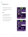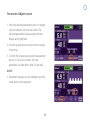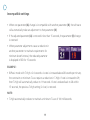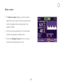
1
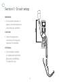
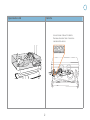
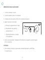
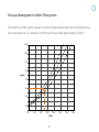
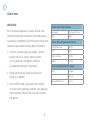
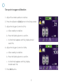
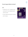
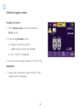
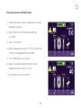
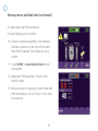
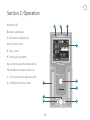
Infant Flow
SiPAP Plus user guide
®
Table of contents
Section 1: Circuit setup.................................. 1
Open bed or crib and isolette.......................... 2
Abdominal sensor........................................... 3
Pressure nomogram for
Infant Flow LP system................................. 4
Alarm test....................................................5-6
Two point oxygen calibration.......................7-8
Disable oxygen sensor..................................... 9
Startup menu and leak test......................10-11
Section 2: Operation.................................... 12
Soft key operation...................................13-14
Operation modes.......................................... 15
Alarm Set/Confirm screen............................. 16
Mode Select screen....................................... 17
Parameter Adjust screen............................... 18
Incompatible settings............................... 19
Main screen.................................................. 20
Monitored Parameter screen......................... 21
Alarm management...................................... 22
Final check and routine inspection................ 23
Troubleshooting............................................ 24
Notes............................................................ 25
i
Section 1: Circuit setup
WARNING:
• Do not attach generator to
patient until verification and
Infant Flow
SiPAP
NCPAP/
Pres Low
L/min
initial setup are complete
Pres High
L/min
14
50
12
10
8
60
5
70
40
80
21
100
90
30
4
3
6
4
2
2
1
CAUTION:
XDCR
• Follow manufacturer’s
instructions for setup and
operation of humidifier
OPTIONAL:
• Use transducer interface
for Apnea and Low Breath
Rate alarm, and BiPhasic
Tr mode (Intl only)
1
PPROX
Open bed or crib
Isolette
Use extension tube with isolette.
Remove extension tube if excessive
condensation occurs.
2
Abdominal sensor placement
1. Connect transducer to driver.
2. Connect respiratory sensor to transducer.
3. Compress the sensor gently; LED on the transducer illuminates.
4. Apply the sensor to the infant:
a. Pressure line perpendicular to tape.
b. Place between the umbilicus
and xiphisternum.
c. Alternative placement—the side
of the abdomen.
5. Verify correct placement. Transducer LED illuminates on expiration, and front panel
LED on inspiration.
OPTIONAL:
• Use transducer interface for Apnea and Low Breath Rate alarm, and BiPhasic
Tr mode (Intl only)
3
Pressure Nomogram for Infant Flow system
The Infant Flow SiPAP system is subject to a direct relationship between the controlled gas flow
and airway pressure. For example, 8 to 9 LPM gas flow provides approximately 5 cmH2O.
15.0
13.0
11.0
9.0
(cmH2O)
7.0
5.0
3.0
1.0
4.0
6.0
8.0
10.0
(LPM)
4
12.0
14.0
16.0
18.0
Alarm test
WARNING:
Alarm test initial settings
Prior to patient application, ensure that all User
Verification testing and calibration procedures are
successfully completed. User Verification testing and
calibration procedures must be done off patient.
Air supply
> 30 psig (2.1 bar)
N/A
High
nCPAP/Press low
9 LPM
1. Connect air and oxygen gas supply. Connect
power cord to AC outlet. Attach patient
circuit, generator and patient interface.
Occlude the opening to the patient.
%O2
30%
Press high flow
3 LPM
Mode
nCPAP
2. Power up the driver and allow Power On
Check to complete.
3. From nCPAP mode, with alarms set, remove
occlusion from opening to patient. Low pressure
alarm activates. Restore the occlusion and rest
the alarms.
5
Infant Flow LP generator/circuit
Use settings below for step 9
Rate
30 bpm
Ti
0.3 sec
Apnea/LBR interval
20 sec
Alarm test (continued)
4. Adjust the nCPAP/Pres Low flow meter to 11 LPM. The high airway pressure alarm activates.
Decrease flow to 8 LPM. Reset the alarms.
5. Adjust the %O2 control to 35%. The High %O2 alarm activates. Return the O2 setting to
30%. Reset alarms.
6. Adjust the %O2 to 25%. The Low %O2 alarm activates. Return the O2 setting to 30%. Reset
the alarms.
7. Disconnect the AC power cord from the wall outlet. The Loss AC alarm activates. Reconnect
the AC power cord. Reset alarms.
8. Occlude exhalation line and increase nCPAP pressure to 11 cmH2O. The High Circuit Pressure
alarm activates. Decrease flow to 8 LPM and reset alarms.
9. Select and confirm BiPhasic mode. Change the mandatory rate control setting to 1. Low
Breath rate alarm activates after the default interval of 20 seconds. Return to rate of 30.
Reset the alarms.
6
Two point oxygen calibration
1. Adjust flow meters and turn on driver.
2. Press the calibration (CAL) button in the Setup screen.
3. Adjust the Oxygen Control to 21%:
a. Allow reading to stabilize.
b. Press the flashing button to confirm.
c. A check mark appears and %O2 display should
read 21%.
4. Adjust the Oxygen Control to 100%:
a. Allow reading to stabilize.
b. Press the flashing button to confirm.
c. A check mark appears and %O2 display
should read 21%.
5.Press Exit button.
7
Two point oxygen calibration (continued)
NOTE:
• If calibration fails, a red “X” is displayed, the alarm
sounds and an Error code is displayed; repeat the
calibration procedure
• Two point calibrations are required with initial setup
and circuit changes
8
Disable oxygen sensor
Disable O2 button
1.From Setup screen, press the calibration
(CAL) button.
2. Press the O2 Disable button:
a. Oxygen monitoring and the
audible oxygen alarms are disabled.
b. Error Code 55 is displayed.
3. Use an external oxygen analyzer to monitor FiO2.
WARNING
• Always use an external oxygen monitor if the
oxygen sensor is disabled.
9
Startup menu and leak test
1. Connect prong or mask to generator; occlude opening to patient.
2. Set nCPAP flow to 9 LPM and High flow
to 3 LPM.
3. Turn on the driver.
4. Verify measured pressure is 5 ±1%. If less than
5 cmH2O is displayed check for leaks.
5. Touch flashing icon to confirm.
6. Adjust O2% dial to desired setting. Verify measured value is within +/- 3%.
7. Touch flashing icon to confirm.
10
Startup menu and leak test (continued)
8. Adjust press High flow as desired.
9. Touch flashing icon to confirm.
10. Connect transducer assembly to the traducer
interface connector on the front of the Infant
Flow SiPAP, if desired. Touch flashing icon to
confirm.
11.Touch NCPAP or Alarm Mute/Reset button
to set alarms.
12. Measured CPAP should be 5 cmH2O. If not, check for leaks.
13. Remove occlusion to prongs or mask. Measured CPAP should drop to 0 to 2 cmH2O. If not, check for occlusions.
11
Section 2: Operation
A.Power LED
A
C
B
B.Alarm warning bar
XDCR
C.Transducer interface LED
D.LCD touch screen
D
E.%O2 control
F. Press high flow meter
Infant Flow®
SiPAP
G.Connection proximal pressure line
NCPAP/
H.Transducer interface connection
L/min
I. Circuit connection inspiratory limb
J. nCPAP/pres low flow meter
Press High
Press Low
L/min
40
30
J
21
50 60 70
80
90
E
100
F
I
H
G
XDCR
12
PPROX
Soft key operation
Description
Example
A button that is enabled.
A button that is inhibited due to non-availability of the designated feature or pending
acknowledgement of an active alarm condition.
A selected mode or control pending confirmation is visually highlighted and intermittently flashes
between yellow and white text.
While a button is pressed, the edges are highlighted to provide a pressed appearance.
13
Soft key operation (continued)
Description
Example
When there is an active alarm associated with a measured value, the measured value concerned
is displayed with RED FLASHING text. The associated limit value (if any) is displayed in RED.
When an alarm that is associated with a measured value is resolved, the device remains in a
LOW priority alarm state, with the measured value displayed in YELLOW FLASHING text and the
associated limit displayed in YELLOW, until the alarms are cleared by the operator.
Manual breath delivers a Biphasic cycle at current settings for T-High, Press High and %O2. Only
one BiPhasic cycle is delivered regardless of button press duration.
If no screen interactions occur for a period of 120 seconds and there are no active alarms, the
screen goes to a “locked” state to prevent inadvertent entries. To unlock the screen, press the
lock icon.
14
Operational modes
CPAP is a constant single level of positive pressure to the infant’s
airway, facilitating the restoration of functional residual capacity
and correction of hypoxemia.
BiPhasic is two levels of pressures, delivered at a set Time High
(T-High) criteria, rate and pressure settings. Small incremental
pressure increases of 2 to 3 cmH2O augment functional residual
capacity and may off load work of breathing.
Low breath rate (LBR) detection is via a respiratory abdominal
sensor. The LBR alarm will be triggered when the set time interval is
exceeded. If the infant’s breath is detected within the next time out
period, the alarm will silence.
15
Alarm set/confirm screen
1.Touch the nCPAP or Alarm button for
3 seconds to set the alarm limits. If neither
button is not touched within 2 minutes,
the alarm limits will automatically be set.
2.The screen will change to Mode
Select screen with the driver operating
in nCPAP mode.
16
Mode Select screen
1.Press the desired mode button. The display will change to the Parameter Adjust screen.
NOTE:
• Only the available modes will be
displayed on the menu bar
1.
• For Low Breath Rate (LBR) modes,
attach the transducer assembly and
respiratory abdominal sensor
17
Parameter Adjust screen
1.Press the desired parameter button to change.
Only the relevant controls are visible. The
selected parameter and associated numeric
display are highlighted.
2.Use the up and down arrow buttons to adjust
the setting.
3.Confirm the change by pressing the parameter
button. If no action is taken, the new
parameter will take effect after 15 seconds.
NOTE:
• Parameter changes can be made during initial
setup and normal operation
18
Incompatible settings
• When one parameter (A) change is incompatible with another parameter (B), the software
will automatically make an adjustment to that parameter (B)
• If the adjusted parameter (A) is restored in less than 15 seconds, the parameter (B) change
is reversed
• When parameter adjustments cause a reduction in
another parameter to maintain requirements for
minimum breath interval, the reduced parameter
is displayed in RED for 15 seconds
EXAMPLE:
• BiPhasic mode with T-High = 2.0 seconds: As rate is increased above 28 breaths per minute,
the constraint on minimum T-Low requires a reduction in T-High. If rate is increased to 29,
then T-High will automatically reduce to 1.9 seconds. If rate is reduced back to 28 within
15 seconds, the previous T-High setting (2.0 sec) is restored.
NOTE:
• T-High automatically reduces to maintain a minimum T-Low of 100 milliseconds.
19
Main screen
• The Main screen displays current mode of
operation alarm status, battery charge status,
monitored parameters and pressure time
graphic display
• Only the active parameters for the selected
mode are available for adjustment
• Press the Change Screen button to access
the Monitored Parameter screen
20
Monitored Parameter screen
1. The Monitored Parameter screen displays
measured values and parameter settings
for all BiPhasic modes.
2. Active parameters are available
for adjustment.
3.Press the Change Screen button to return
to the Main screen.
21
Alarm management
Audible alarm priority • High priority: A series of 10 tones every
10 seconds, flashing red
• Medium priority: Three audible tones every 15 seconds, flashing yellow
• Low priority: Two audible tones every
30 seconds, solid yellow
Silencing audible alarms Pressing the Alarm Reset button will silence
active alarms for up to 30 seconds. A new
high priority alarm condition will cancel the
alarm silence.
Resetting alarms Press the Alarm Reset button for 3 seconds
to clear resolved and low priority alarm and to
rest alarm limits.
22
Final check and routine inspection
Inspect the system at least every 3 to 4 hours to:
• Ensure the patient is receiving the prescribed level of CPAP
• Ensure the generator is stable, secure and not pulling upward on the nose
• Check for deformation or irritation to the nose or surrounding tissue
• Ensure the patient’s septum is clearly visible when using prongs
• Ensure the patient’s eyes are clearly visible and the nares are not blocked, when using masks
• Inspect the fixation device and straps for proper tension and adjust as needed to maintain
a proper fit
• Monitor the patient for gastric insufflation and abdominal distension
• Monitor for excessive condensation in circuit and generator
23
Troubleshooting
Alarm
Priority
Possible cause
Potential actions
%O2 < 18%
High
O2 CAL required
Reset FiO2 above limit, O2 CAL
%O2 < 104%
High
O2 CAL required
Reset FiO2 below limit, O2 CAL
High %O2
High
%O2 setting changed, supply gas
failure, water trap overflow
Correct FiO2, reset alarm limits
Low %O2
High
Blender setting changed, supply gas
failure, water trap overflow
Correct FiO2, reset alarm limits
Over pressure
High
Flow Rate set too high, occlusion of
exhalation limb, blocked silencer/filter
Check exhaust tube/filter, reduce flow
rate, reset alarm limits
Low battery
Warning
Battery charge status change
Connect to AC
Low battery voltage
Medium
Battery disconnect, fails to hold charge
Connect to AC
Loss AC
High
AC power disconnected
Connect to AC
High nCPAP/
Press Low
High
Setting change, circuit disconnect
Reset alarm limits
Low nCPAP/
Press Low
High
Setting change, circuit disconnect, leak
Reset alarm limits, check for leaks
High BiPhasic pressure
High
Press High setting change,
circuit disconnect
Reset alarm limits
24
Notes
25
WARNING—U.S. Federal Law restricts this device to sale by or on the order of a physician.
CareFusion
22745 Savi Ranch Parkway
Yorba Linda, CA 92887
800.231.2466 toll-free
714.283.2228 tel
714.283.8493 fax
carefusion.com
© 2012 CareFusion Corporation or one of its subsidiaries. All rights reserved. Infant Flow, CareFusion and the CareFusion logo are
trademarks or registered trademarks of CareFusion Corporation or one of its subsidiaries. RC767 (0912/2000) L3429 Rev. B