1
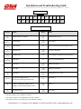
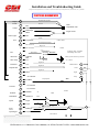
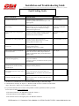
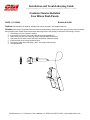
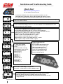
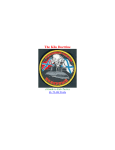
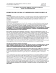
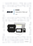
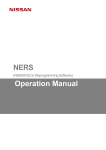
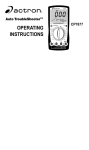
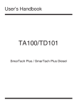
Installation and Troubleshooting Guide
All rights reserved. Reproduction or use of content, in any manner, without express written permission by CDI Electronics, Inc., is prohibited.
Marine Instrument Cluster
VDO Service Manual
(Rev 4)
January 14, 2008
Model Year 2000 Cluster Functions
I/O Cluster Functions:
• Speedometer
Options:
270° cross-coil movement
80 MPH (270° scale)
60 MPH (270° scale)
50 MPH (270° scale)
• Tachometer (6000 RPM)
-
270° cross-coil movement
• Fuel Level
-
90° cross-coil movement, Low Fuel Telltale
• Pressure
-
90° cross-coil movement, Low Oil Pressure Telltale
• Coolant Temperature
-
90° cross-coil movement, High Temp. Telltale
• Voltage Level
-
90° cross-coil movement, Voltage Warning Telltale
• Trim
-
90° cross-coil movement
• Audible Alarm
-
Continuous tone unit, minimum of 100 dBsp, engine
signal warnings and system fault conditions.
• Depth Sounder
-
Single row 4 digit, 7 segment, LC display and
telltales for FEET or METERS, shallow water
alarm.
• Mode and Adj. Button inputs
-
Select modes and update display
• Clock
-
HH:MM, 7 segment, LCD
• Odometer and Trip Odometer
-
0.0 to 9999 miles or km, 7 segment, LCD
• Engine Hours and Trip Hours
-
0.00 to 9999 hours, 7 segment, LCD
• Seawater Temperature
-
30.0 to 104.0ºF or –1.0 to 40.0ºC, 7 segment, LCD
VERY IMPORTANT!! CONNECT THE NEW ADDITIONAL GROUND WIRE FROM
THE CLUSTER TO ENGINE GROUND
(You will have to run additional wire from the cluster through the boat to the engine)
CDI Electronics • 111 Commerce Circle • Madison, AL 35758 • Fax 256-772-5701 • www.cdielectronics.com
Installation and Troubleshooting Guide
All rights reserved. Reproduction or use of content, in any manner, without express written permission by CDI Electronics, Inc., is prohibited.
O/B Cluster Functions:
• Speedometer
Options:
270° cross-coil movement
80 MPH (270° scale)
60 MPH (270° scale)
60 MPH (220° scale)
50 MPH (270° scale)
• Tachometer (7000 RPM)
-
270° cross-coil movement
• Engine System Monitor
-
Red warning telltales and audible alarm for:
Low oil tank level
High engine temperature
No oil pressure
Check Engine
• Fuel Level
-
90° cross-coil movement, Low Fuel Telltale
• Voltage Level
-
90° cross-coil movement, Voltage Warning Telltale
• Trim (Optional)
-
90° cross-coil movement
• Audible Alarm
-
Continuous tone unit, minimum of 100 db’s, engine
signal warnings and system fault conditions.
• Depth Sounder
-
Single row 4 digit, 7 segment, LC display and
telltales for FEET or METERS, shallow water
alarm.
• Mode and Adj. Button inputs
-
Select modes and update display
• Clock
-
HH:MM, 7 segment, LCD
• Odometer and Trip Odometer
-
0.0 to 9999 miles or km, 7 segment, LCD
• Engine Hours and Trip Hours
-
0.00 to 9999 hours, 7 segment, LCD
• Seawater Temperature
-
30.0 to 104.0ºF or –1.0 to 40.0ºC, 7 segment, LCD
CDI Electronics • 111 Commerce Circle • Madison, AL 35758 • Fax 256-772-5701 • www.cdielectronics.com
Installation and Troubleshooting Guide
All rights reserved. Reproduction or use of content, in any manner, without express written permission by CDI Electronics, Inc., is prohibited.
Operator Interface
A four character, 7 segment LCD display and two additional dashboard mounted buttons make up the operator
interface. The display uses a colon (:) for the clock display and a decimal point (.) to show more accurate
values.
To show the various information displays, the operator presses the MODE button to advance through the
available displays. Dial legends surrounding the LCD display are highlighted by pointer symbols above and
below the numeric segments. Depth sounder mode is indicated by lighting the FEET or METERS telltale
located to the right of the LCD.
TRIP
HRS
ºF
1 2:3.4
TRIP
KM
MODE
ºC
ADJ
Buttons
SET/Reset
Note: A quick start guide showing all functions and settings can be found in the back of this booklet.
Main Function Descriptions: V 1.0
Tachometer: 0-6000 RPM I/O, 0-7000 RPM O/B. The Tachometer input is selected at the boat-builder for the
number of pulses per engine revolution using VDO calibration software. Pulse ranges are 1-10 per engine
revolution.
Speedometer: The speed of the boat is measured using the paddle wheel input from the transom
mounted traducer (AIRMAR P-32). The speed values can be adjusted up and down by use of the
VDO calibration software. See Customer Service Bulletin 99-001 (page 10) and Customer Service
Bulletin 6.25.99 (page 11) in the back of this booklet.
Fuel Gauge: The fuel level is measured using a standard US Ohm (240-330 Ώ) sensor (Default) or
selecting a VDO range 10-180 Ώ sensor using the VDO calibration software.
Alarm: A low fuel warning symbol will illuminate when the level reaches 1/6th of a tank or less.
Fault: US Range = less than 15 Ώ or more than 280 Ώ.
VDO Range = less than 3 Ώ or more than 210 Ώ.
In a fault condition, the pointer will return to empty and the horn will “beep” every 2 seconds up
to a max of 10 seconds. The telltale will stay on until the problem is resolved.
CDI Electronics • 111 Commerce Circle • Madison, AL 35758 • Fax 256-772-5701 • www.cdielectronics.com
Installation and Troubleshooting Guide
All rights reserved. Reproduction or use of content, in any manner, without express written permission by CDI Electronics, Inc., is prohibited.
Coolant Temperature Gauge: The temperature is measured using either a standard US range sensor (Default) or a
VDO range sensor can be selected using the VDO calibration software.
Alarm: The Temperature telltale will light, the horn will “Beep” for 10 seconds if the engine temperature rises
above 213º F.
Fault: An Ohm value below 37 Ώ US (27 Ώ VDO) or above 800 Ώ US (500 Ώ VDO) will illuminate the telltale,
“Beep” the horn, and move the pointer to the fully “HOT” position.
OIL Pressure Gauge: Oil pressure (0-80 PSI) is measured using a standard US 240-33 Ώ US range sensor (Default)
or a VDO 10-180 Ώ range sensor can be selected using the VDO calibration software. See Customer Service
Bulletin 07-001 (page 15).
Alarm: The Oil telltale will light and the horn will “Beep” for 10 seconds if the Oil pressure drops below 6 PSI.
Fault: An Ohm value below 15 Ώ US (3 Ώ VDO) or above 280 Ώ US (210 Ώ VDO) will illuminate the telltale,
“Beep” the horn every 2 seconds, and move the pointer to the “zero” position.
Voltage Gauge: The voltage is measured from the ignition switch input with a scale of 10-16 volts.
Alarm: “The Battery” telltale will light and the horn will “Beep” for 10 seconds if the voltage measures below
11 volts or above 16 volts.
Fault: The cluster will shut down if the voltage drops below 7 volts or above 16.5 volts in order to protect
voltage sensitive components. The Clock and Depth default settings may have to be reset.
Trim Gauge: The trim gauge is driven by the OEM engine trim sensors and must be selected using the VDO
Calibration Software. The cluster can be programmed for current Honda, OMC, Mercury and Yamaha trim
values.
Alarm: None
Fault: None.
Outboard System Monitor (O/B clusters ONLY)
The clusters for outboard engine crafts include the outboard engine system monitor. It provides warning
telltales and an audible alarm for the Oil Pressure, Engine Temp, Oil Level and Check Engine signals for OMC
System Check sensor equipped outboard engine.
OIL PRESSURE
The telltale shall turn on any time the Oil Pressure warning switch contact closes and the ignition is on. The
Telltale shall remain on for a minimum of 30 seconds, and remain on until the fault is corrected and the sensor
contact opens or the ignition is turned off.
ENGINE TEMPERATURE
The telltale shall turn on any time the Engine Temperature warning switch contact closes and the ignition is on.
The telltale shall remain on for a minimum of 30 seconds, and remain on until the fault is corrected and the sensor
contact opens or the ignition is turned off.
CHECK ENGINE
The telltale shall turn on any time the Check Engine warning switch contact closes and the ignition is on. The
telltale shall remain on for a minimum of 30 seconds, and remain on until the fault is corrected and the sensor
CDI Electronics • 111 Commerce Circle • Madison, AL 35758 • Fax 256-772-5701 • www.cdielectronics.com
Installation and Troubleshooting Guide
All rights reserved. Reproduction or use of content, in any manner, without express written permission by CDI Electronics, Inc., is prohibited.
contact opens or the ignition is turned off.
OIL LEVEL
The telltale shall turn on any time the Oil Level warning switch contact closes and the ignition is on. The
telltale shall remain on for a minimum of 30 seconds, and remain on until the fault is corrected and the sensor
contact opens or the ignition is turned off.
HORN CONTROL
This audible alarm control sounds the horn any time one of the four described alert conditions occur while the
engine is running above 500 RPM. The horn will sound for 10 seconds and then turn off.
SELF-TEST
When the ignition is turned on, the outboard monitor system will perform a self-test. The self-test shall consist
of a ½ second beep by the audible alarm horn and all four of the warning tell tales shall turn on. At the end of
the test, all four of the telltales will turn off in sequence.
CLOCK DISPLAY
The Clock display is selected by pressing the MODE button. During Clock display, the colon blinks once per
second.
SETTING CLOCK:
To set the time of day, press and hold MODE and ADJUST buttons for 2 seconds while in Clock Display mode.
The MODE button is then used to advance through the time set features. Hours are set first, minutes second and
the 12/24 hour mode last. The selected digits will blink while being set. While in set mode, ADJUST is used to
increment the selected unit of time. Hours are set in the 24 hour format, rolling to zero after 24. Minutes roll to
zero after 60. While setting the 12/24 hour mode, 24 is displayed in the hours position and 12 is displayed in the
minutes position. The current setting will blink (i.e. 12 will blink if the 12 hour mode is set). MODE and ADJUST
are de-bounced for 3/8th’s of a second (You have to press and hold the buttons for over 3/8th’s of a second to
change value). If the ADJUST is pressed and held for 2 seconds while setting a numeric value, the key auto
repeats at a rate of 6 per second (To scroll through all 60 minutes requires 12 seconds). When the ignition is
turned off, the present mode is saved and the LCD displays the time of day. Time setting functions are not
available while the ignition switch is turned off. When the ignition switch is turned back on, the LCD display
returns to it’s prior display mode.
POWER SAVER:
The clock keeps time for up to 21 days after the ignition is turned off. During this time, the system is in it’s power
saving state. After 21 days, the cluster shuts down to conserve battery power. When the ignition switch is turned
back on after 21 days, the clock restarts at midnight in the mode that was active when the ignition switch was
turned off. The time must be reset.
DEPTH DISPLAY
Water depth is measured using an external transducer (AIRMAR “P32 or P19” 200 kHz). It works by measuring
the reflected energy of a 200 kHz pulse as it bounces off of the bottom (The transducer depends upon water to
act as conductor for the pulsed sound waves). Depth measurement is based upon the speed of sound in fresh
water at 68º F (25º C). Small errors can result, depending upon the salinity and temperature of the water.
The display indicates depth in feet (1 to 300 foot range) or tenth of meters (0.5 to 100.0 meter range). Accuracy
beyond 300’ depends upon bottom conditions, salinity, transom angle, transducer installation and aiming of the
transducer. CDI Electronics has no part in the installation of the transducers and cannot warranty the operation of
a part over which we have no control. The 300’ operation in salt water is with an AIRMAR P19-U transducer
pointed fully down. Performance of the transducer at speed is affected by air bubbles in the water and the ability
of the transducer to maintain contact with the wake.
CDI Electronics • 111 Commerce Circle • Madison, AL 35758 • Fax 256-772-5701 • www.cdielectronics.com
Installation and Troubleshooting Guide
All rights reserved. Reproduction or use of content, in any manner, without express written permission by CDI Electronics, Inc., is prohibited.
A shallow water depth alarm feature can be set in increments of 1’ (0.3m). The operator sets the valve by
pressing and holding the dashboard mounted MODE and ADJUST buttons for 2 seconds. Entering shallow water
causes a continuous chirping sound and blinking up/down arrow segments. The shallow water depth alarm setting
is displayed as blinking digits. Currant depth is displayed as steady (Not blinking) digits. If the alarm screen is
blank, no shallow water alarm is set. If the depth screen shows dashes, the depth is zero or indicates a bad
sensor reading.
Pressing the MODE button initiates “Set Mode”. The shallow water alarm setting blinks along with the down
arrows on the display. Pressing ADJUST sets the alarm toward deeper water. Pressing MODE again indicates the
up arrows. With the up arrows on, pressing ADJUST sets the alarm toward shallower water. Pressing and holding
ADJUST for longer than 1 second speeds up the process of making the alarm setting deeper or shallower.
Pressing the MODE button again allows the depth measurement units to be changed. While in “Units Mode”, the
shallow depth alarm setting blinks and the “FEET” or “METERS” telltale flashes. Pressing ADJUST changes
between FEET and METERS. Pressing MODE again allows the depth sounder system to be enabled or disabled.
In this mode, a blinking message “ON” or “OFF” appears. Pressing ADJUST changes between Sounder On and
Sounder Off. In the “OFF” mode, the sounder no longer sends out its periodic sonar ping. The “OFF” mode
should be used when using Fish Finders or other equipment that has the same 200 kHz frequency to
avoid “Cross-Talk”.
Pressing “MODE” again causes a return to normal “Depth Mode”. A time-out feature causes the display to
automatically return to depth mode if no button is pressed within 30 seconds.
In Depth Display Mode, pressing ADJUST displays the shallow water alarm setting and the alarm blinks for 10
seconds. When shallow water is encountered, the up/down arrows blink and the audible alarm beeps. Pressing
ADJUST turns the beeper off, but only for the current low water event. Entering deeper water re-enables the
beeper for the next shallow water encounter.
ODOMETER (LOG) and TRIP ODOMETER (TRIP LOG)
The Log calculates total mileage based on input from the paddlewheel. This value cannot be reset except by the factory
or CDI Electronics and is stored in nonvolatile memory.
The Trip Log is a distance log that can be reset and will display distance accumulated since last reset. The operator
presses both “MODE” and “ADJUST” while in the Trip Log mode to reset to “Zero”.
The Log and Trip Log functions will display Statute Miles when the Depth function displays “FEET”. Kilometers will be
displayed when the Depth function displays “METERS”.
ENGINE HOURS
Total engine running hours (above 500 RPM) will be displayed in 1 hour increments.
TRIP HOURS
This function keeps track of the engine hours with Hour/Minute resolution up to 100 hours maximum. Pressing both
“ADJUST” and “MODE” while in Trip Hour mode resets the values to “Zero”.
SEAWATER TEMPERATURE
This function measures the water temperature at the transducer (AIRMAR P32 or equivalent). When the Depth function is
in “FEET”, the function defaults to “º F” (Fahrenheit). When the Depth function is in “METERS”, the temperature defaults
to “º C” (Centigrade).
CDI Electronics • 111 Commerce Circle • Madison, AL 35758 • Fax 256-772-5701 • www.cdielectronics.com
Installation and Troubleshooting Guide
All rights reserved. Reproduction or use of content, in any manner, without express written permission by CDI Electronics, Inc., is prohibited.
Connector
12
11
10
9
8
7
6
5
4
3
2
1
24
23
22
21
20
19
18
17
16
15
14
13
(Harness Side View)
Electrical Pin-out
Pin No.
1
Signal
Pin No.
13
Depth Transducer Signal In
14
GND (Depth)
Depth Shield
Bare Wire
Black/Purple
3
Depth transducer return
Black
Blue
2
Signal
GND (Signal)
15
Spare (Test/PGM Signal Prototypes only)
16
Seawater Temperature
Black/Purple
4
GND (Power)
Bare Wire
5
Tan/Black
Lighting Input
17
Check Engine Warning Switch (O/B Only)
Trim Input
18
Oil Level Switch (O/B Only)
19
MODE Push-Button
Dark Blue
6
Purple/White
7
Serial TX
Pink/Brown
8
20
Serial RX
ADJUST Push-Button
Pink/Blue
9
21
Fuel Input
Pink
10
Light Blue
11
Speed Sensor (+), 12 V out
Purple/Green
Oil Pressure Input (I/O) or
Oil Pressure Warning Switch (O/B)
Tan
Engine Temperature Input (I/O) or
Engine Temp. Warning Switch (O/B)
12
Tachometer Input
Grey
22
Ignition (B+)
Purple
23
Battery (+)
Red/Blue
24
Speed Input
Grey/Pink
• The pin connectors are an AMP P/N: 770988-1
• The cluster connector is an AMP Mate-N-Lok P/N: 770587-1
• The extractor tool for removing the pins is an AMP P/N: 455822-2
CDI Electronics • 111 Commerce Circle • Madison, AL 35758 • Fax 256-772-5701 • www.cdielectronics.com
Installation and Troubleshooting Guide
All rights reserved. Reproduction or use of content, in any manner, without express written permission by CDI Electronics, Inc., is prohibited.
FUNCTIONAL DIAGRAM WIRE
Depth +
Ground
Ground
Depth Finder Signal In
1
2
Ground
DS01
Blue
Depth Finder Cable
3
Black/Purple
Black/Purple
4
Shield
Cluster Lights
5
Blue
Trim
6
Purple/White
Ground
Engine Ground
Speedo
0.0Ω to 542Ω
Dash Light & Compass
7
N/C Serial TX
8
N/C Serial RX
Engine IO
9
Oil Pressure
10
Light Blue
Pink
Water Temp
11
10
Tan
12
11
Grey
13
12
Black
14
13
Shield
Depth Ground
15
14
16
15
240 Ω @ 6 PSI TO 33Ω @ 100 PSI
75 to 857Ω
Engine IO
Shield Ground
1
Power
2
Engine IO
Red
Engine IO
Signal
1
Green
3
2
Temp
No Connection
Temp Speedo
4
White
Tan/Black
4
17
No Connection
18
No Connection
Sea Water
US Range 10Ω F to 280Ω Ε
VDO Range 3Ω to 210Ω
Potentiometer
Attenuator Black/Pink
Resistor
Fuel Sender
Fuel
Tachometer
Ground
Set Button
19
18
Pink/Blue
Mode Button
20
19
Pink/Brown
Speedo
21
20
Purple
22
Purple
Ground
Set
Black
Mode
3A
Switched 12 V
Power Speedo +12
Power
Power
23
22
Red/Purple
Speeds Signal
24
Grey/Pink
5A
15A
+12V
+12Volt Power
1
24
2,3,4,13 and 14 are grounded internally
CDI Electronics • 111 Commerce
Circle • Madison, AL 35758 • Fax 256-772-5701 • www.cdielectronics.com
24
Installation and Troubleshooting Guide
All rights reserved. Reproduction or use of content, in any manner, without express written permission by CDI Electronics, Inc., is prohibited.
Fault Finding Guide
Observed Problem
Field Procedure
Reference
No function with key on
-Check for voltage on pins 22 & 23.
-Check for ground connection between pin 4 and
engine ground.
See “Volt Gauge”
Erratic function, Pointers flickering and
horn chirping
If Mercury O/B, check for correct inductive spark
plugs necessary on 50, 70, 90 and 120 HP models.
Inductive spark plugs are needed due to voltage
spikes from the ignition coils.
-VDO Bulletin 7.10.99
- Mercury recommended
application.
Speed & Depth stop working at high
speed
-Check for transducer position mounting. Transducer
is likely too low and cavitating. Transom mount
should be nearly flush with bottom.
See AIRMAR installation
Bulletin.
Speedometer not working, Depth OK
-Check connections on 24 pin connector.
-Check for voltage change from 0 to 8 V while
turning paddle one blade at a time.
See VDO Bulletin 6.25.99
Alarm horn sounds, Tank light on, Fuel
level is OK.
-Check tank sending unit for Ohm values.
-Check ground on sensor.
-Remember an open circuit is a fault.
See “Fuel Gauge”
Alarm “chirps” with key on while the
boat is on the trailer.
- The depth transducer will mimic a depth of 0.7 ft
while out of the water. Shallow Depth Alarm will
sound if a depth alarm value is present. Reset alarm
depth to “Zero”
See “Depth”
Trim Gauge will not go full down or
Trim not working properly.
-Check OEM trim sender for positioning and range.
(May not be installed)
-If gauge is erratic as you raise/lower the unit, replace
the trim sender.
Depth and Clock settings reset to “0”
with the key off. Clock not working
with the key off.
Check for voltage on pin 23 (This should read battery
voltage for memory function).
Alarm Sounds, Low Oil Warning Light
stays on but Oil pressure within range of
7 to 80 PSI.
Add a 470Ω ½ watt resister from Light Blue sense
wire to engine ground. If this fixes problem, oil
sending unit was out of calibration. If not fixed, have
cluster repaired
Display shows PROG or ADJ when key
is turned on and will not change.
Disconnect Mode & Adjust switch. If normal display
appears, replace switch. If problem still shows, have
cluster repaired
• An Alarm is a constant tone for 10 seconds, telltale will stay on after tone stops.
• A Fault alarm is caused by an “Open” or “Shorted” sender circuit or a sender out of the normal
range. The tone is a “Beep every 2 seconds for 10 seconds.
• If you cannot determine the root cause of the problem or need a replacement, contact your local
service center or email [email protected].
• The cluster connector is an AMP Mate-N-Lok P/N: 770587-1
• The pin connectors are an AMP P/N: 770988-1
• The extractor tool for removing the pins is an AMP P/N: 455822-2
CDI Electronics • 111 Commerce Circle • Madison, AL 35758 • Fax 256-772-5701 • www.cdielectronics.com
Installation and Troubleshooting Guide
All rights reserved. Reproduction or use of content, in any manner, without express written permission by CDI Electronics, Inc., is prohibited.
Customer Service Bulletins
Four Winns Dash Panels
DATE: 11/11/2003
Bulletin # 99-001
Problem: Speedometer not working, possibly due to wires crossed in the paddle wheel plug.
Solution: Determine if the speedometer circuit has crossed wires by checking the wires going into the male plug before
doing anything else. Please follow the directions below and refer to the drawing to determine if the wiring is correct.
1. If the wiring is correct, check the module.
2. If the wiring is incorrect, remove the male plug from the female plug.
3. Remove the pins from the male plug using the special AMP removal tool.
4. Check the pins for broken wires and loose connections. Clean as needed.
5. Install the wires in the correct numbered hole.
6. Connect the male and female plugs. (Note: The plugs are directional).
7. Test speedometer.
CDI Electronics • 111 Commerce Circle • Madison, AL 35758 • Fax 256-772-5701 • www.cdielectronics.com
Installation and Troubleshooting Guide
All rights reserved. Reproduction or use of content, in any manner, without express written permission by CDI Electronics, Inc., is prohibited.
DATE: 11/11/2003
Bulletin # 6.25.99
Problem: Speedometer not working.
Solution: Determine if the speedometer circuit has failed.
1. Connect a DC voltmeter to the “Green” (Signal) and “Bare” (GND) wires of the transducer.
2. With the keyswitch “on”, rotate the paddle wheel one blade at a time. The voltage should switch between “0”
and “8” volts as the blades pass by the body of the transducer.
3. If the voltage does not change as the paddle is slowly rotated, replace the transducer.
4. When installing a new transducer, always check it before mounting it. Use jumper wires to power the unit.
Transducer Cable Leads Diagram
Red, 12 V+ (Positive)
Black, 12 V (Ground)
Bare, Shield Ground
Blue, Depth Signal
Transducer Cable
Green, Speed Signal
White (Optional Temp)
Tan (Optional Temp)
CDI Electronics • 111 Commerce Circle • Madison, AL 35758 • Fax 256-772-5701 • www.cdielectronics.com
Installation and Troubleshooting Guide
All rights reserved. Reproduction or use of content, in any manner, without express written permission by CDI Electronics, Inc., is prohibited.
Customer Service Bulletins
Four Winns Dash Panels
DATE: 11/11/2003
Bulletin # 7.10.99
Problem:
The 12 V supply from the Mercury 3 and 4 cylinder engines is carrying an unusually high level of RF/EMI noise
due to voltage induction from the ignition coils.
This RF/EMI noise will cause the LCD clusters to “reset” and “Beep” erratically due to the over-voltage protection
built into the LCD cluster. The RF/EMI noise has not been known to damage the LCD clusters. However, the LCD clusters
will not operate correctly until the noise is eliminated. Unprotected sensitive electronics, such as transducers and audio
equipment, can be damaged by the RF/EMI noise.
Solution:
Install INDUCTIVE type spark plugs to eliminate the RF/EMI noise. Check the recommended application. Note:
Inductive NGK spark plugs have a “Z” in the part number (i.e. BUZHW).
Tek Rm: 50ks/s
Sample
Tek Rm: 50ks/s
0.000 VDC
Sample
0.000 VDC
A
A
A-1
100 V 50ms
M 5ms ch1 / 32mV
Figure 1, Before inductive plugs.
100 V 50ms M 5ms ch1 / 32mV
Figure 2, After inductive plugs.
CDI Electronics • 111 Commerce Circle • Madison, AL 35758 • Fax 256-772-5701 • www.cdielectronics.com
Installation and Troubleshooting Guide
All rights reserved. Reproduction or use of content, in any manner, without express written permission by CDI Electronics, Inc., is prohibited.
Customer Service Bulletins
Four Winns Dash Panels
DATE: 11/11/2003
Bulletin # 4.28.99
Problem: Erratic functioning of the Alarm and Alarm Fault circuits.
The Marine Cluster uses voltage comparator circuits for gauge functions and to activate various alarms and/or
fault functions. This design eliminates the need for separate switches and facilitates the ability to program
different parameters. This system requires a good ground path to prevent errors.
Solution:
Install a separate dedicated ground wire (Minimum 16 gauge) from the Engine block (Or Battery Negative post) to
the cluster to ensure proper functioning of the Alarm and Fault Alarm circuits. Be sure to remove the old ground
wire connection between the cluster and fuse panel. See diagram below:
Ground Circuit Diagram
NEW GROUND WIRE,
(16-gauge minimum)
Cluster
--
+
Battery
Fuse Panel
Engine
Lights, etc.
Fuel Sender
CDI Electronics • 111 Commerce Circle • Madison, AL 35758 • Fax 256-772-5701 • www.cdielectronics.com
Installation and Troubleshooting Guide
All rights reserved. Reproduction or use of content, in any manner, without express written permission by CDI Electronics, Inc., is prohibited.
Customer Service Bulletins
Four Winns Dash Panels
DATE: 11/11/2003
Bulletin # 6.3.99
Problem: Erratic functioning/Reset of the Cluster when the signal horn is used .
The Marine Cluster uses voltage comparator circuits for gauge functions and to activate various alarms and/or
fault functions. The signal horn may cause a momentary voltage drop when used (Exceeding the Clusters 7 volt
working lower limit), causing the Cluster to shut off as a protection for the Cluster’s processor. The Cluster will
reset when the horn button is released. However, the depth and clock settings will be reset to default values (“No
depth alarm” and “12:00”) and will need to be reset.
Solution:
Installing a 10uf, 50 V non-polarized Capacitor between the 2 horn wires to eliminate this problem.
The Capacitor may be obtained from most electronics stores (Radio Shack’s P/N: 272-999). See diagram below:
Horn Circuit Modification Diagram
To Switch
(White/Orange)
+
CAP
---
Horn
To Ground
(Black)
CDI Electronics • 111 Commerce Circle • Madison, AL 35758 • Fax 256-772-5701 • www.cdielectronics.com
Installation and Troubleshooting Guide
All rights reserved. Reproduction or use of content, in any manner, without express written permission by CDI Electronics, Inc., is prohibited.
Customer Service Bulletins
Four Winns Dash Panels
DATE: 7/19/2004
Bulletin # 07-001
Problem: Oil Pressure warning horn sounding and oil pressure reading too high or too low in dash meter.
Solution: Determine if the oil pressure is actually low by reading the pressure with a mechanical gauge before
proceeding. Please follow the directions below.
1. If the oil pressure is above 6 PSI or below 80 PSI, use an ohmmeter to check the resistance on the oil pressure
sender (should read less than 240 ohms) from the terminal to engine ground. See the following chart for the
approximate values:
Oil Pressure
6
10
15
20
30
40
50
60
70
80
90
100
Ohms Reading
234
228
210
191
156
130
112
93
72
57
45
33
2. If you read more than 240 ohms at 6 PSI or less than 33 ohms at 80 PSI, the sender is bad and needs to be
replaced.
3. If you read approximately the correct ohms at the different pressures, the sender is working correctly and the
wiring needs to be checked.
4. Check the resistance from the light blue wire in the connector (pin # 10) at the dash to engine ground. Refer to the
chart above and compare the readings to the ones obtained in step 3. If the readings are close, the dash panel
has a fault and needs to be repaired.
CDI Electronics • 111 Commerce Circle • Madison, AL 35758 • Fax 256-772-5701 • www.cdielectronics.com
Installation and Troubleshooting Guide
All rights reserved. Reproduction or use of content, in any manner, without express written permission by CDI Electronics, Inc., is prohibited.
Quick Start
Front Panel Programming Features
For VDO Marine Instrument Module
To determine if Module is Front Panel Programmable switch key to “ON”.
The module will cycle through a self test and then display the software revision
level. This is also indicated on the identification label located next to the harness.
2.3
ProG
A
1
b
0
C
0
d
1
E
0
F
1
END
Software level 2.0 and greater are capable of being configured for the following functions using the
MODE and ADJUST buttons
Press MODE and ADJUST buttons and turn on power module. Hold MODE and ADJUST buttons
for five seconds unit the display shows “P r o G”, release buttons. Press MODE button to select
function and ADJUST to make changes.
A= Tachometer: Adjustable from 1-12 pulses per revolution.
Press and hold ADJUST button with “up” arrows to increase pulses per
revolution. Releasing button displays “down” arrows, press and hold to decrease.
Engines: IO 4cyl = 2 pulses, 6cyl = 3 pulses, 8cyl = 4 pulses
OB All Mercury, OMC, Johnson, and Evinrude = 6 pulses
Yamaha = 6 pulses, except 70 HP and lower = 3 pulses
Suzuki = 6 pulses, except 65 HP and lower = 3 pulses
Tohatsu/Nisssan = 6 pulses, except 70 HP and lower = 2 pulses
Honda = 2 pulses, except on 35 HP - 50 HP = 3 pulses
C= Trim: Press and hold
ADJUST button with “up”
arrows
to increase number, releasing
button displays “down” arrows,
press and hold to decrease.
Mercury IO = O
Mercury OB = 1
OMC IO = 2
Volvo IO = 3
OMC OB = 4
Evinrude OB = 5
Johnson OB = 6
Honda OB = 7
Yamaha OB = 8
b= Speed: Adjustable from
-50% to +50%.
Press and hold ADJUST button with
“up” arrows to increase pulses per
mile (reduce indicated speed).
Releasing button displays “down”
arrows. Press and hold ADJUST
button to reduce pulses per mile
(increase indicated speed).
D= Fuel, E = Coolant temp, F = Oil pressure
U.S. sensor = 1, VDO sensor = 0. Press ADJUST to select
Pressing both MODE and ADJUST buttons for 2 seconds will save change.
Releasing buttons will exit programming mode and restart module.
If no button is pressed for 20 seconds the program will automatically save any
changes and exit.
CDI Electronics • 111 Commerce Circle • Madison, AL 35758 • Fax 256-772-5701 • www.cdielectronics.com
Installation and Troubleshooting Guide
All rights reserved. Reproduction or use of content, in any manner, without express written permission by CDI Electronics, Inc., is prohibited.
Thank you for using CDI Electronics.
8/30/2007
CDI Electronics • 111 Commerce Circle • Madison, AL 35758 • Fax 256-772-5701 • www.cdielectronics.com