1
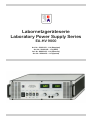
Labornetzgeräteserie Laboratory Power Supply Series EA-HV 9000 Art. Nr.: 26100103 - 114 (Standard) Art. Nr.: 26400103 - 114 (IEEE) Art. Nr.: 26600103 - 114 (Ethernet) Art. Nr.: 2690x103 - 114 (Special) Technische Daten / Technical specifications Modell Model HV 9000-1K2-2000 HV 9000-2K-2000 HV 9000-4K-2000 HV 9000-6K-2000 HV 9000-12K-2000 Ausgangsspannung Ausgangsstrom Ausgangleistung Artikelnummer ** 1200 V 2000 V 4000 V 6000 V 12 kV 1,67 A 1A 500 mA 350 mA 170 mA 2000 W 2000 W 2000 W 2000 W 2000 W 26100103 26100104 26100114 26100105 26100106 Output voltage Output current Output power Article number ** Technische Daten Serie HV 9000 / Technical specifications Series HV 9000 Netzeingang / Mains input Stromaufnahme / Input current consumption Leistungsfaktor / Efficiency Entstörung / Interference suppression Anschlüsse / Terminals Hochspannungs-Ausgang / High voltage output 90...264 VAC / 50/60 Hz max. 10 Aeff (230 V) cos ϕ ≥0,98 EN 50081 Teil 2 und EN 50082-2 Programmierbuchse Sub-D / Analogue interface Sub-D Eingänge / Inputs: Sollwerte U und I, 0...10 V / Target values U & I Referenz-Spannung + 10 V / Reference voltage Interlockschleife / Interlock loop Ausgänge / Outputs: Monitorspannungen für U und I, 0...10 V / Monitors U & I Referenz-Spannung + 10 V / Reference voltage Hochspannungs-Koaxialbuchse mit zusätzlicher Erdbuchse High voltage coaxial socket with additional grounding socket SPANNUNGSREGELUNG / VOLTAGE CONTROL Einstellbereich / Adjustment range Regelgenauigkeit / Regulation accuracy Abweichung bei Eingangsspannung ±10% Difference at input voltage Leerlauf-Vollast-Differenz / No load - full load - difference Spannungseinbruch bei 50% Laststromsprung Voltage breakdown at 50% load current leap Ausregelzeit bei 50% Laststromsprung / Settling time at 50% load change Dynamischer Innenwiderstand / Dynamic internal resistance 1...10 Hz 10...100 Hz 100...10.000 Hz Stabilität über 8 Stunden / Stability over 8 hrs Temperaturstabilität / Temperature stability Restwelligkeit / Ripple 0...100% ≤ 0.05% ≤ 0.05% ca. / approx. 2% ≤ 2 ms ≤ 0,2% von RLnenn / of RLnom )* ≤ 1% von RLnenn / of RLnom )* ≤ 10% von RLnenn / of RLnom )* ≤ 0.01% ≤ 50ppm/K ≤ 0.05% STROMREGELUNG / CURRENT CONTROL Einstellbereich / Adjustment range Regelgenauigkeit / Regulation accuracy Abweichung bei Eingangsspannung ±10% Difference at input voltage +10% Abweichung Kurzschluß/Vollast / Difference short-circuit/full load Stabilität über 8 Stunden / Stability over 8 hrs Temperaturstabilität / Temperature stability Restwelligkeit / Ripple 0...100% ≤ 0.05% ≤ 0.05% ≤ 0.05% ≤ 500ppm/K ≤ 0.05% ANZEIGE / DISPLAY Genauigkeit Spannungwerte / Accuracy of voltage indication Genauigkeit Stromwerte / Accuracy of current indication ±0,2% + 2 Digits ±1% + 2 Digits ANALOGE SCHNITTSTELLE / ANALOGUE INTERFACE Genauigkeit Eingang Uset / Accuracy of input Uset Genauigkeit Eingang Iset / Accuracy of input Iset Genauigkeit Ausgang Umon / Accuracy of output Umon Genauigkeit Ausgang Imon / Accuracy of output Imon < 0,4% < 1,3% < 0,5% < 1% IEEE Schnittstelle / IEEE Interface Auflösung / Resolution Fehler / Error 12 Bit ±1 LSB 19'', 3 HE/U, 466 mm 13 kg Abmessungen (B H T) / Dimensions (W H D) Gewicht / Weight (* RLnenn = Umax / Imax (** der Standardmodelle / of standard models © EA Elektro-Automatik, DE-41747 Viersen, Helmholtzstr. 31-33, Tel. 02162-3785-0, Fax. 02162-16230 3 Allgemeines / General Hochspannungs-Netzgeräte Serie HV 9000 High Voltage Power Supply Series HV 9000 Die Stromversorgungen der Serie HV9000 sind frequenzmodulierte Resonanzkonverter mit Gegentaktschaltfrequenzen bis 200 kHz im Leistungsbereich bis 2000 Watt. Durch trapezförmigen Spannungsverlauf und Schalten im Nulldurchgang liegt der Wirkungsgrad der Schaltstufe bei 99%. Dieses moderne Konzept gestattet in Verbindung mit Mehrfachregelschleifen den Aufbau von präzisen Hochspannungssystemen bis 12 kV mit überlegenen Regeleigenschaften. Die Geräte sind netzseitig leistungsfaktorkorrigiert und für alle Netzspannungen im Bereich von 90...264 V AC ausgelegt. Dadurch ist der Betrieb mit einer Ausgangsleistung bis 2 kW aus einer normalen SchukoSteckdose möglich. The power supplies of the series HV9000 are frequency modulated resonance converters. The push-to-push switching frequencies are up to 200 kHz in the power range of 500 to 2000 W. Because the trapezoid shaped voltage is switched when passing zero the efficiency of the switching stage is nearly 99%. This modern concept in connection with multi-regulation loops allows the construction of precise high voltage systems up to 12 kV with outstanding regulation performances. The mains input is 90...264 V / 50-60 Hz with an active power factor correction. Funktion Function Die Geräte arbeiten nach neuester Technologie und werden als Tischgehäuse ausgeliefert, können aber mit dem beiliegenden Umrüstsatz auf 19" geändert werden. Sie sind mit 10-Gang-Potentiometern zur Einstellung von Spannung und Strom, sowie digitalen Anzeigeinstrumenten und Zustandsmeldungen ausgestattet. Extern sind Spannung und Strom mit 0...10 V programmierbar (SPS-Steuerung) und entsprechend dem augenblicklichen Zustand von Strom und Spannung stehen analoge Monitorspannungen 0...10 V zur Verfügung. In Verbindung mit der IEEE Schnittstelle sind praktisch alle Systemanwendungen möglich. Eine Interlockschleife ist am externen Programmieranschluß vorhanden. Die Geräte der Serie HV9000 sind überschlags- und dauerkurzschlußfest, wobei Spannung und Strom von 0...100% regelbar sind. Nach einem starken Einbruch der Ausgangsspannung schaltet das Gerät für eine kurze, vorgegebene Zeit ab und startet dann mit einer Rampe bis zur eingestellten Spannung. Die in den Ausgang gelangende Energie wird somit auf ein Minimum reduziert. Deshalb sind Anwendungen mit Röhren, Gasentladungsprozessen und Kondensatorladung möglich. Die Ausgangsrestwelligkeit ist kleiner als 5x10⁻⁴ Vpp bei vollem Nennstrom. Diese ist vom entnommenen Ausgangsstrom abhängig und nach wirtschaftlichen und praktischen Gesichtspunkten (Gewicht, Größe) festgelegt. Für 30% des vollen Ausgangsstromes (600 Watt Ausgangsleistung) ist die Restwelligkeit schon kleiner als 1x10⁻⁴ Vpp. The units are delivered as desktop versions, but can be modified to 19" racks with the included kit. Voltage and current are adjusted with 10-turn potentiometers, the values can be preset in standby mode and are displayed on digital meters. The operation modes are indicated by LEDs. The output voltage and current can be externally set by means of an external voltage of 0...10 V for 0...rated value (PLC control). The two external monitor outputs (U & I) each provide an output voltage of 0...10 V for 0...rated value. In connection with the IEEE.2 interface practically all systems applications are possible. An interlock loop is available on the programming terminal. Für Sonderanwendungen wird eine Ausführung mit besonders niedriger Restwelligkeit von unter 0,01% geliefert. For special applications a unit with extreme low ripple <0.01% is available The units of the series HV9000 are flashover- and continuous short-circuit-proof, whereas voltage and current are still adjustable from 0...100%. On a large fallback of the output voltage the unit is switched off for a short time and than automatically starting slowly again from 0 V to the preset voltage. The energy reaching the output is therefore reduced to a minimum. So applications with tubes, plasma-gas discharging processes and capacitor charging are possible. The output ripple is less than 5x10⁻⁴ Vpp on max. rated output current. The ripple depends on the actual output current. On 30% of the rated output current (600 Watts output power) the ripple is less than 1x10⁻⁴ Vpp. © EA Elektro-Automatik, DE-41747 Viersen, Helmholtzstr. 31-33, Tel. 02162-3785-0, Fax. 02162-16230 4 Beschreibung / Description Anzeigeinstrumente Instruments Die Geräte sind mit getrennten digitalen Volt- und Amperemetern ausgerüstet. Die Anzeige erfolgt auf beleuchteten 3½stelligen 13 mm LCD-Anzeigen. Die Anzeigen können unabhängig zwischen den eingestellten Spannungs- und Stromsollwerten und den jeweiligen Istwerten umgeschaltet werden. The units are equipped with separate illuminated 3½ digit 13 mm LCD volt- and ampere meters. In both cases it is possible to independently switch between the value set, the actual value or the OVP value. Ferneinstellung der Ausgangsspannung Remote adjustment of the output voltage Die Ausgangsspannung kann mit einer externen Spannung von 0...10 V für U0 ...Umax ferneingestellt werden. Die Anschlüsse dafür befinden sich auf der Rückseite der Geräte. The output voltage can be externally set by means of an external voltage of 0...10 V for U0 ...Umax. The terminals for the external programming are on the rear of the unit. Ferneinstellung des Ausgangsstromes Remote adjustment of the output current Der Ausgangsstrom kann mit einer externen Spannung von 0...10 V für I0...Imax ferneingestellt werden. Die Anschlüsse dafür befinden sich auf der Rückseite der Geräte. The output current can be externally set by means of an external voltage of 0...10 V for 0...10 V for I0...Imax. The terminals for the external programming are on the rear of the unit. IEEE Bus / Ethernet IEEE bus / Ethernet Die Geräte können mit einer optionalen IEEE- oder Ethernetschnittstelle ausgerüstet werden. Der Anschluß befindet sich jeweils auf der Rückseite der Geräte. Nähere Information über die Meß- und Steuermöglichkeiten finden Sie im Handbuch zur IEEE-Option bzw. zur Ethernet-Option. As an option, the units can be equipped with an IEEE bus interface or an Ethernet interface. The connection terminals are located on the rear of the unit. Further details about measuring and control features of the IEEE or Ethernet option are available in the option's user instruction manual. Hochspannungsausgang High voltage output Der Hochspannungsausgang befindet sich auf der Rückseite. Aufgrund des sehr weiten Ausgangsspannungsbereichs ergeben sich unterschiedliche Ausgangskonfigurationen bzgl. Klemmung der Ausgangspole sowie der Hardware der Ausgangsanschlüsse. Der Ausgang ist mit einem Hochspannungssteckverbinder der Y-Serie von LEMO ausgerüstet. Er ist intern umpolbar (nur im Werk). Serienmäßig ist intern der „-“ auf PE geklemmt, so daß „+“ am Innenleiter des Steckverbinders liegt. Der Schirm (Außenleiter) liegt auf PE. Spannungsführend ist der Innenleiter. The high voltage output is located on the rear of the unit. Because of the wide output voltage range there are different output configurations regarding the termination of polarisation. The output is equipped with a high voltage connector of Yseries from LEMO. The polarity can be reversed internally (only in the factory). By default, the "–“ is internal connected to PE, so "+" is connected with the centre wire of the HV connector. The screen is connected to PE. The centre wire leads the high voltage, the screen may not be used as a part of the load wire. Der Schirm darf nicht als Lastleitung benutzt werden. Die Rückleitung muß auf die PEKlemme geführt werden. GND liegt immer auf PE. The screen may not be used as load connection. The return line must be connected to the PE terminal. GND is always connected to PE. Typenbezeichnungen Hersteller LEMO: HV-Buchse: ERA 1Y405 HV-Stecker: FFA 1Y405 HV-Leitung: 106330 Part names (manufacturer LEMO): HV socket: ERA 1Y405 HV plug: FFA 1Y405 HV lead: 106330 © EA Elektro-Automatik, DE-41747 Viersen, Helmholtzstr. 31-33, Tel. 02162-3785-0, Fax. 02162-16230 5 Beschreibung / Description Ausgänge Outputs Bei den Geräten mit HV und LEMO-Anschlußbuchsen liegt am beiliegenden Verbindungskabel der Schirm (Außenleiter) auf Erdpotential. Stromführend ist der Innenleiter. Der Schirm darf nicht als Lastleitung benutzt werden. Die Last darf nur an den Innenleiter der HV-Leitung (Hi) und an den Minus-Ausgang (Lo) angeschlossen werden. Soll ein Betriebsmittel an die Geräte-Erde angeschlossen werden, so ist dazu die Schutzleiterklemme (PE-Zeichen) zu benutzen. On units with HV and LEMO connection sockets the screen of the supplied connection cable is earthed. Only the centre wire leads the output current. The screen must not be used as load cable. The load must only be connected to the centre wire of the HV cable (Hi) and to the negative output (Lo). In case a load unit should be connected to the earth of the unit use the safety ground connector (PE symbol). Überspannungsschutz (OVP) Overvoltage protection (OVP) Alle Geräte besitzen serienmäßig einen Überspannungsschutz. Mit dem Trimmer auf der Frontplatte läßt sich jeder Spannungswert zwischen 1% und 101% der max. möglichen Ausgangsspannung einstellen. Der eingestellte OVP-Spannungswert wird am Voltmeter angezeigt nachdem der Tastschalter "OVP" betätigt wurde und die LED "Preset" leuchtet. Wird die festgelegte Spannungshöhe aus irgendeinem Grunde (Fehlbedienung, defekte Bauteile, Fremdspannung) überschritten, wird der Taktgeber gesperrt und somit wird keine weitere Energie an den Ausgang geliefert. Die LED "OVP" leuchtet auf. Durch drücken der ResetTaste wird das Gerät erneut betriebsbereit. All units are equipped with an overvoltage protection as standard. Any value between 1% and 101% of the max. rated voltage can be set with the trimmer on the front panel. The preset OVP value is indicated on the voltmeter after activating the "OVP" switch and the "Preset" LED lights on. If the output voltage becomes, for any reason, higher than the preset voltage (e.g. operators fault, defective components, external voltage), the switching oscillator is blocked, and no further energy comes to the output. The LED "OVP" lights on. To reset the OVP to normal, the “Reset” button must be activated. Der OVP schützt die angeschlossene Last vor Überspannung, die in Fehlersituationen entstehen kann. Deshalb sollte die OVP-Einstellung stets auf die aktuelle Situation angepaßt werden The OVP protects connected loads from possible damage due to overvoltage. It is recommended to always adjust the OVP value according to the situation. Bereitschaft (Standby) Standby operation Mit dem Tastschalter "Output" kann der Ausgang abgeschaltet werden. Die LEDs am Schalter zeigen den Zustand des DC-Ausgangs an, aber nur bei manueller Bedienung. Die LED "Off" leuchtet = Ausgang Null. Die LED "On" leuchtet = Ausgang aktiv. The output voltage can be switched off with the pushbutton "Output". The LEDs on the switch indicate the DC output condition, but only during manual control. The LED "Off" lights on = output zero. The LED "On" lights on = output active. Bei Fernsteuerung zeigen die LEDs den Zustand des Ausgangs nicht an! The LEDs do not indicate the DC output condition in remote control! Spannungs- und Stromeinstellung Voltage and current adjustment Die gewünschten Ausgangssollwerte können im Stand-by Betrieb mit 10-Gang Potentiometern vorgewählt werden. Hierzu sind die Tastschalter "Voltage" bzw. "Current" zu betätigen, wobei die LED "Preset" den Modus "Sollwert" und die LED "Actual" den Modus "Istwert" anzeigt. The values of the voltage and current can be preset in standby mode by means of 10-turn precision potentiometers. The push switches "Voltage" respectively “Current” must be activated, the corresponding LED “Preset” lights on and the preset value is indicated on the meters. The LEDs "Actual" indicate that the actual values are displayed on the meters. © EA Elektro-Automatik, DE-41747 Viersen, Helmholtzstr. 31-33, Tel. 02162-3785-0, Fax. 02162-16230 6 Beschreibung / Description Installation Installation Vor Inbetriebnahme des Gerätes sollten das Gehäuse, die Bedien- und Anzeigeelemente sowie das Netzkabel auf Beschädigung hin untersucht werden. Der mitgelieferte Sub-D Stecker muß angeschlossen werden. Falls eine Beschädigung erkennbar ist, sollte das Gerät nicht mit dem Netz verbunden werden. Vor dem Öffnen des Gerätes muß unbedingt der Netzstecker gezogen werden. Before taking the unit into operation it is necessary to inspect the housing, the controls etc. for signs of physical damage. The supplied Sub-D plug must be connected. If any damage is found, the unit may not be operated on the mains. Disconnect the mains plug before opening the unit. Reparatur, Wartung oder Kalibrierung darf nur durch eine Fachkraft erfolgen. Servicing, repairs or calibrations should only be carried out by trained engineers. Der Anschluß des Gerätes darf nur an eine Schutzkontaktsteckdose erfolgen. Falls ein Austausch der Sicherung notwendig ist, sind nur Sicherungen gleichen Typs und Stromwertes zu verwenden. Dabei muß das Gerät vom Netz getrennt sein! The unit must be operated only on the voltage stipulated on the type plate. If it is necessary to change the fuse, it is imperative that it is only replaced by one of same value and physical dimensions as the original supplied fuse. The unit must be disconnected from the mains whilst replacing the fuse. Erdung Grounding Das Gerät ist über das Netzanschlußkabel geerdet. Aus diesem Grunde darf der Netzanschlußstecker nur in eine Schutzkontaktsteckdose eingeführt werden. Diese Schutzmaßnahme darf nicht durch Verwendung einer Verlängerungsleitung ohne Schutzleiter unwirksam gemacht werden. The unit may only be operated using a properly wired and grounded mains plug as the grounding of the unit leads via the earth line of the power cable. This safety feature must not be disabled by using an extension cable without a ground lead. Vorsicht! Am Gerät sind Teile berührbar, die hohe Spannungen führen. Es darf deshalb nicht ohne komplett geschlossenem Gehäuse betrieben werden. Außen am Gerät berührbare Teile, die hohe Spannung führen, sollten wenn möglich mit einem geerdeten Käfig versehen werden, welcher einen Kontakt besitzt, der beim Öffnen die Interlockschleife des Gerätes unterbricht. ATTENTION! The unit generates hazardous voltages. It must not be operated by untrained personnel and not with open cover! Parts leading dangerous voltage should, if possible, be covered by a grounded cage which has an breaker contact that interrupts the interlock loop. Kühlung Cooling Um einen ausreichenden Luftstrom zu gewährleisten, sind die Luftauslaßöffnungen stets frei und sauber zu halten. It is important that the air circulation remains unimpeded at all times. Übertemperaturabschaltung und -meldung (OT) Bei übermäßiger Erwärmung (z.B. Luftein- und austritte verschmutzt, Lüfter defekt usw.) werden die Geräte automatisch abgeschaltet und die LED "OT" leuchtet auf. Die Wiedereinschaltung erfolgt nach Abkühlung automatisch. Die OT-LED meldet zusätzlich, wenn das LOCK-Signal auf der hinteren Analogschnittstelle nicht gebrückt ist. Overtemperature protection (OT) If the unit is overheated (e.g. fan defective, ventilation inand outlets dirty etc.), it will automatically switch off and the LED "OT" will light on. After cooling down the unit will switch on automatically. The OT LED also indicates that the LOCK signal on the analog interface (rear side of device) is not bridged. Umgebungsbedingungen Während des Betriebes, auch bei Dauerbetrieb und Volllast, darf die Umgebungstemperatur 0...50 °C betragen. Die Lagertemperatur kann zwischen -40 °C und +70 °C liegen. Die maximale relative Luftfeuchtigkeit beträgt 90% nicht kondensierend. Ambient conditions During operation, at full load or constant operation, the ambient temperature may lie between 0...50 °C. The storage temperature can be between -40 °C and +70 °C. The relative humidity should not exceed 90%, non-condensing. © EA Elektro-Automatik, DE-41747 Viersen, Helmholtzstr. 31-33, Tel. 02162-3785-0, Fax. 02162-16230 7 Beschreibung / Description Einstellung von Strom und Spannung Setting voltage and current Ausgangsspannung und Ausgangsstrom können mit jeweils einem Potentiometer bestimmt werden. Der Betriebszustand wird von zwei Leuchtdioden angezeigt: “CV” = Spannungsregelung (grün) “CC” = Stromregelung (rot) Output voltage and output current are adjustable with two potentiometers coarse and fine on the front panel. The operation mode is indicated by two LEDs: "CV" = Constant Voltage (green) "CC" = Constant Current (red) Ferneinstellung der Ausgangsspannung Remote setting of the output voltage (ext. voltage) Die Ausgangsspannung kann mit einer Spannungsquelle (0...10 V = 0 V...Umax) extern über die Programmierleiste eingestellt werden. In diesem Fall ist das Potentiometer zur Einstellung der Spannung (auf der Frontplatte) ohne Funktion. Die externe Spannung ist anzulegen gemäß der Pinbelegung auf Seite 14. For remote setting of the output voltage connect a external control voltage of 0...10 V according to the table. An external voltage of zero volt (0 V) is equivalent to 0 V on the output, 10 V external is equivalent to the nominal output voltage of the power supply. The external voltage is connected according to the pin assignment on page 15. The potentiometer for voltage adjustment on the front panel is out of function. Ferneinstellung des Ausgangsstromes Remote setting of the output current Der Ausgangsstrom kann mit einer Spannungsquelle (0...10 V = 0 A...Imax) extern über die Programmierleiste eingestellt werden. In diesem Fall ist das Potentiometer zur Einstellung des Stromes (auf der Frontplatte) ohne Funktion. Die externe Spannung ist anzulegen gemäß der Pinbelegung auf Seite 14. For remote setting of the max. output current connect a external control voltage of 0...10 V. An external voltage of zero volt (0 V)is equivalent to 0 A on the output, 10 V external is equivalent to the nominal output current of the power supply. The external voltage is connected according to the pin assignment on page 15. The potentiometer for current adjustment on the front panel is out of function. Fernsteuerung über digitale Schnittstelle (optional) Remote control via digital interface (optional) Mit einer digitalen, optionalen Schnittstelle (IEEE oder Ethernet) lassen sich mit Hilfe eines Rechners die Sollwerte für Strom und Spannung extern vorgeben und die Istwerte einlesen. Die Umschaltung zwischen Normalbetrieb und Fernsteuerbetrieb erfolgt automatisch, wenn die Schnittstelle von einem Rechner aus angesprochen wird. Am Netzgerät leuchtet dann die LED „EXTERN“. Um den Normalbetrieb wieder herzustellen, wird am Netzgerät der Taster „LOCAL“ betätigt (nur IEEE-Bus). Alternativ setzt der Befehl *RST die Schnittstelle zurück und das Gerät schaltet wieder auf manuelle Bedienung um. Sollte sich digitale Schnittstelle, aus welchem Grund auch immer, mal nicht mehr ansprechen lassen, ist das Gerät aus- und wieder einzuschalten. Folgende Funktionen sind bei diesem Netzgerät nutzbar: The device can be optionally equipped with an IEEE bus or Ethernet interface. With this interface it is possible to control voltage and current by means of a computer. The change-over between manual operation and remote control happens automatically with the first command that is sent to the device. The LED "EXTERN" on the power supply will indicate the state of the external control. To switch back to manual operation, pushbutton "LOCAL" can be used (only with the IEEE bus). Alternatively, the command *RST will also reset the interface and switch the device back to manual control. In case the digital interface does not react anymore, due to any reason, switch the unit off and on again. Istwerte Strom/Spannung messen Sollwerte Strom/Spannung setzen Standby (Ausgang ein/aus) setzen Stromregelung aktiv (CC) erfassen Measure actual values of voltage/current Set values of current/voltage Set standby(output on/off) Read Current Control active state (CC) Following functions are available with this power supply: © EA Elektro-Automatik, DE-41747 Viersen, Helmholtzstr. 31-33, Tel. 02162-3785-0, Fax. 02162-16230 8 Beschreibung / Description Betriebsartenanzeigen Mode indication Mit der LED "CV" wird angezeigt, daß das Gerät als Konstantspannungsquelle, und mit der LED "CC", daß das Gerät als Konstantstromquelle, arbeitet. Diese Umschaltung geschieht vollautomatisch. If the LED "CV" is lit, the unit operates as a constant voltage source, while the LED "CC" indicates that the unit is operating as a constant current source. The change-over happens automatically. Überlastschutz & Stromregelung Overload protection and current regulation Der Ausgang ist dauerkurzschlußfest. Der max. Strom läßt sich kontinuierlich von 0 bis Nennstrom einstellen. The output is protected against a continuous short-circuit. The max. output current is continuously adjustable from zero up to the rated current. Programmierung von Ausgangsspannung und -strom Remote programming of output voltage and current Über die analoge Schnittstelle besteht die Möglichkeit Spannung und Strom fern zu steuern, sowie die aktuellen Strom und Spannungswerte auszuwerten. Die maximalen Spannungs- und Stromwerte sind dabei auf 10 V normiert mit einer Genauigkeit von <0,2%. Die Monitorsignale Spannungs- und Stromistwert sind ohne weitere Beschaltung an den entsprechenden Pinnen verfügbar. Pin 7 = IMON Pin 8 = UMON Die Leitungsenden sollten mit einem Widerstand und einem Kondensator zur Unterdrückung von Störeinflüssen abgeschlossen werden, z.B. 100 kOHM und 470nF. Die Monitorausgänge sind kurzschlußfest und mit 1 mA belastbar. Es sollte eine geschirmte Leitung verwendet werden, wobei der Schirm geräteseitig an Pin 10 angeschlossen wird und am Leitungsende offen bleibt oder mit dem Signal GND verbunden wird. Das Gehäuse des 15 poligen D-Sub-Steckers hat Schutzleiterverbindung und sollte nicht mit dem Schirm der Signalleitung verbunden werden. Die Spannungs- und Stromsollwerte können einzeln oder gemeinsam über die hochohmigen (MOhm) Steuereingänge vorgegeben werden. Die Verbindungen am mitgelieferten Stecker Pin 3 und 4 (Spannung) sowie Pin 5 und 6 (Strom) müssen geöffnet werden. Die + Referenz Pin 2 wird mit einer Seite eines Potentiometers und die 0 V-Referenz Pin 1 mit der anderen Seite des Potentiometers verbunden. Der Schleifer wird mit UPS Pin 3 (Spannung) bzw. mit IPS Pin 5 (Strom) verbunden. Pin 2 und Pin 4 werden nicht beschaltet. It is possible to control output voltage and current externally via the analogue interface as well to monitor the actual values externally. The maximum rated voltage and current values are standardized to 10 V with an accuracy of <0.2%. The monitor signals are available on the respective outputs. Pin 7 = IMON Pin 8 = UMON Fernsteuerung ein/aus Mit dem SB (Pin 9) kann das Schaltnetzteil in den Standby Betrieb versetzt werden. Dazu muß Pin 9 mit +5 V Pin 12 verbunden werden, entweder über einen Relaiskontakt oder über einen Transistor mit offenem Kollektor. Wird diese Verbindung wieder geöffnet, steigt die Ausgangsspannung wieder mit Softstartverhalten auf den voreingestellten Spannungssollwert an. Remote on/off Through the control input SB (Pin 9) the unit can be switched into standby mode (output voltage off). This is effected by connecting Pin 9 to +5 V Pin 12 through a relay contact or a transistor with open collector. After opening this connection the output is switched on again and rises up to the preset value. The end of the monitor cable should be terminated by a resistor (e.g. 100 k Ohm) and a capacitor (e.g. 470nF). The monitor outputs are short-circuit protected and the max. load is 1 mA. The cable should be screened. The screen must be connected to Pin 10 (GND). The housing of the 15-pole Sub-D plug is connected to PE and may not be connected to the screen of the monitor cable. The voltage and current values can both be set via the high impedance control inputs. The connections on the supplied 15-pole plug on Pin 3 and 4 (Voltage) and Pin 5 and 6 (current) must be opened. The + reference Pin 2 is to be connected to one side of a potentiometer and the 0 V reference Pin 1 to the other side of the potentiometer. The slider of the potentiometer must be connected to UPS Pin 3 (Voltage) resp. to IPS Pin 5 (Current). Pin 2 and Pin 4 are not connected. © EA Elektro-Automatik, DE-41747 Viersen, Helmholtzstr. 31-33, Tel. 02162-3785-0, Fax. 02162-16230 9 Bedienelemente / Operating controls Bedienelemente Frontplatte Front panel 1. Netzschalter 1. Mains switch 2. Schalter Ausgang Ein - Aus (Standby) Stellung On = Ausgangspannung vorhanden Stellung Off = keine Ausgangsspannung 2. Switch output on/off (standby) Position on = output voltage on Position off = output voltage off 3. Reset-Taster Dieser dient zur Rücksetzung der OVP. 3. Reset switch Serves to reset the OVP. 4. Schalter Preset/Normal für OVP In Stellung Preset wird die gewünschte Überspannungsschwelle mit einem Schraubendreher an dem Trimmer OVP (Nr. 5) eingestellt. Nach Einstellung wieder auf Normal schalten! 4. Switch Preset/Normal for OVP In position "Preset" the desired OVP threshold can be set by means of a screw driver with the trimmer OVP (No. 5) Switch back to normal operation after setting it! 5. Trimmer zur OVP-Einstellung Mit diesem Trimmer wird die gewünschte Spannung eingestellt, bei der die OVP ansprechen soll. 5. Trimmer for setting OVP threshold This trimmer sets the OVP threshold voltage. 6. Local Mit diesem Taster kann von IEEE-Bus Betrieb auf Normalbetrieb umgeschaltet werden. Funktioniert nicht bei Ethernet! 6. Local This switch is used to switch from IEEE bus mode back to standard mode. Does not work with Ethernet option! 7. Schalter Preset/Actual Spannung In der Stellung Preset zeigt das Voltmeter 13 die vorgewählte Spannung an, eingestellt mit Regler 9. In der Stellung Actual wird die tatsächliche Ausgangsspannung angezeigt. 7. Switch Preset/Actual Voltage In position Preset the voltmeter 13 indicates the preset voltage, adjusted with potentiometer 9. In position Actual the actual voltage is indicated. 8. Schalter Preset/Actual Strom In der Stellung Preset zeigt das Amperemeter 14 den vorgewählten max. Ausgangsstrom an. Regler 12. In der Stellung Actual wird der tatsächliche Ausgangsstrom angezeigt. 8. Switch Preset/Actual current In position Preset the ampere meter 14 indicates the preset max. output current, adjusted with potentiometer 12. In position Actual the actual current is displayed. 9. Potentiometer Spannung Potentiometer zur Einstellung der Ausgangsspannung. 9. Potentiometer Voltage Potentiometer for the output voltage adjustment. 10. Potentiometer Strom Regler zur Einstellung der Strombegrenzung. 10. Potentiometer Current Potentiometer for the max. output current. 11. Voltmeter Das Voltmeter dient zur Anzeige der gewünschten Ausgangsspannung, der gewünschten Spannungsschwelle zur Überspannungsabschaltung sowie der tatsächlichen Ausgangsspannung. 11. Voltmeter The voltmeter displays the preset and the actual value of the output voltage, as well as the OVP threshold. 12. Amperemeter Das Amperemeter dient zur Anzeige des gewünschten Ausgangsstromes, sowie des tatsächlichen Ausgangsstroms. 12. Ammeter The ammeter displays the preset and the actual value of the output current. © EA Elektro-Automatik, DE-41747 Viersen, Helmholtzstr. 31-33, Tel. 02162-3785-0, Fax. 02162-16230 10 Betrieb / Operation Hinweise zum Betrieb Notes for the operation Der Betrieb mit kapazitiven Lasten ist nicht problemlos möglich. Bedingt durch den internen Aufbau des Gerätes ist folgendes zu beachten: Es dürfen nicht beliebig hohe Kapazitäten am DCAusgang angeschlossen und aufgeladen werden. Die max. verträgliche Kapazität ist vom Modell abhängig: 1,2 kV Modell: 4 mF 2 kV Modell: 1 mF 4 kV Modell: 250 μF 6 kV Modell: 100 μF 12 kV Modell: 35 μF Operating the high voltage power supply with a capacitive load is not unproblematic. Due to the internal construction of the devices, following restrictions apply: • It is not allowed to connect any capacity to the DC output, in order to charge/discharge it • The max. allowed capacity on the DC output is depending on the model: 1,2 kV model: 4 mF 2 kV model: 1 mF 4 kV model: 250 μF 6 kV model: 100 μF 12 kV model: 35 μF Müssen für einen bestimmten Anwendungszweck größere Kapazitäten verwendet werden, so kann das nur durch eine Anpassung des Gerätes (intern) möglich gemacht werden. Die Anpassung ist auf Anfrage erhältlich und wird im Werk durchgeführt. Kontaktieren Sie uns für Einzelheiten. In case it is absolutely required to connect higher capacities, the device would have to have an internal modification installed. This modification can be done upon request, but only in the factory. Please contact us for details. • • © EA Elektro-Automatik, DE-41747 Viersen, Helmholtzstr. 31-33, Tel. 02162-3785-0, Fax. 02162-16230 11 Frontansicht / Front view 11 1 2 3 4 5 6 7 8 12 9 10 1 Netz / Ein-Aus Schalter / Mains switch 2 Ausgang: Ein/Aus (Standby) / Output: on/off (standby) 3 Reset (Rücksetzung bei IEEE-BUS) / Reset (resets the IEEE bus) 4 Preset/Normal (Einstellung OVP) / Preset/Normal (adjustment OVP) 5 Trimmer zur OVP Einstellung / Adjusting the OVP threshold 6 Local (Umschaltung IEEE-Normalbetrieb) / Switch back to normal mode 7 Preset/Actual Spannung / Voltage 8 Preset/Actual Strom / Current 9 Spannungseinstellung / Voltage adjustment 10 Stromeinstellung / Current adjustment 11Voltmeter 12Amperemeter © EA Elektro-Automatik, DE-41747 Viersen, Helmholtzstr. 31-33, Tel. 02162-3785-0, Fax. 02162-16230 12 Rückansicht / Rear view A B C D E Rückansicht Standardmodell / Rear view of standard model A DC-Plus-Ausgangsbuche HV (DC-Minus-Ausgangsbuchse bei Modellen mit umgekehrter Polung) B Erdebuchse (DC-Minus bei Standardausführung, DC-Plus bei Modellen mit umgekehrter Polung C Luftauslaß mit Lüfter D Öffnungen für optionale GPIB/RS232-Schnittstelle E Analogschnittstelle (zum Normalbetrieb mit Brückenstecker U und I) A DC Plus output socket HV (DC minus output socket at models with reversed polarity) B Ground socket (DC minus at standard models, DC plus at models with reversed polarity C Air exhaust with fan D Slot for optional GPIB/RS232 interface E Analog interface (during normal operation used with bridge plug for U and I) © EA Elektro-Automatik, DE-41747 Viersen, Helmholtzstr. 31-33, Tel. 02162-3785-0, Fax. 02162-16230 13 Analoge Schnittstelle Pinbelegung der analogen Schnittstelle (Sub-D, 15polig) 1 2 3 4 5 6 7 8 9 10 11 12 13 14 15 0 V-Referenz + Referenz (0...10 V) UPS (Eingang Sollwert-Spannungs-Potentiometer 0...10 V UPOT (Ausgang Sollwert-Spannungs-Potentiometer 0...10 V IPS (Eingang Sollwert-Strom-Potentiometer 0...10 V) IPOT (Ausgang Sollwert-Strom-Potentiometer 0...10 V) IMON (Ausgang Istwert-Strom 0...10 V) UMON (Ausgang Istwert-Spannung 0...10 V) SB (Stand-by) Steuereingang: +5 V = Stand-by, offen = Betrieb GND (Masse/0 V für externe Programmierung) LOCK (Sicherheitsschleife/Verriegelung für HV-Last) +5 V Ausgang. Für SB-Betrieb auf Pin 9 legen Nicht belegt +15 V Ausgang Nicht belegt Grundeinstellung für normalen Betrieb Bei normalem Betrieb des Gerätes müssen die folgenden Verbindungen an der analogen Schnittstelle gemacht werden: Pin 3 - Pin 4 (Durchschleifung Spannungssollwert) Pin 5 - Pin 6 (Durchschleifung Stromsollwert) Pin 10 - Pin 11 (Lock-Schleife) Diese Verbindungen bestehen bereits an dem mitgelieferten Sub-D Stecker. Ausgangsanschlüsse auf der Rückseite (grün/gelb) + oder – Ausgang an innerem Kontakt, je nach Polung (Standard ist +) Schirm ist mit Schutzleiter PE verbunden und darf nicht als Rückleiter für den Laststrom benutzt werden. PE Schutzleiter und Rückleitung für die Last Schnittstellen (je nach Ausführung) 24-poliger Buchsen - Anschluß IEEE-Bus Schnittstelle (wenn vorhanden) 9-poliger Sub-D Anschluß RS-232 Schnittstelle (wenn vorhanden, zusammen mit IEEE oder Ethernet) 15-poliger Sub-D Anschluß Analoge Schnittstelle (muß immer beschaltet sein) RJ45-AnschlußEthernet-Port (wenn vorhanden) © EA Elektro-Automatik, DE-41747 Viersen, Helmholtzstr. 31-33, Tel. 02162-3785-0, Fax. 02162-16230 14 Analogue interface Pin connection on the analogue interface, Sub-D 15 pole 1 0 V-Reference 2 + Reference (0...10 V) 3 UPS (Input preset voltage potentiometer 0...10 V 4 UPOT (output preset voltage potentiometer 0...10 V 5 IPS (Input pre set current potentiometer 0...10 V) 6 IPOT (output pre set current potentiometer 0...10 V) 7 IMON (output actual value current 0...10 V) 8 UMON (output actual value voltage 0...10 V) 9 SB (Standby) control input: +5 V = OFF (standby), open = ON 10 GND (GND/0 V for external programming) 11 LOCK (safety loop / inhibit for HV load) 12 +5 V output (for standby mode connect to pin 9) 13N.C. 14 +15 V output 15N.C. Fundamental settings for normal operation For normal operation the following connections must be carried out on the analogue interface: Pin 3 - Pin 4 (loop-through of voltage set value) Pin 5 - Pin 6 (loop-through of current set value) Pin 10 - Pin 11 (LOCK loop-through) These connections are already made at the included Sub-D plug. Output terminals on the rear side + or – output on the central contact, depending on polarity (standard is +) The screen is connected to the safety ground PE and must never be connected to the load. (green/yellow) PE safety earth, return path for the load Interfaces (according to setup) 24-pole socket 9-pole Sub-D connector 15-pole Sub-D connector RJ45 connector IEEE bus interface (if equipped) RS-232 interface (if equipped, always with IEEE or Ethernet) Analogue interface (must always be plugged) Ethernet port (if equipped) © EA Elektro-Automatik, DE-41747 Viersen, Helmholtzstr. 31-33, Tel. 02162-3785-0, Fax. 02162-16230 15 Hinweise / Hints Hinweise zur Bedienung Hints and tips - Der Netzanschlußstecker muß an eine frei zugängliche Steckdose angeschlossen werden. - The mains plug must be connected into a free accessible mains socket. - Der Ausgang kann innerhalb des Gerätes mit der Platine "UMPOLER" umgepolt werden. Dieses darf jedoch nur von entsprechendem Fachpersonal durchgeführt werden. - The polarity of the output can be internally reversed by means of the PCB "UMPOLER". This may only be carried out by trained personnel. -- Der Überspannungsschutz (OVP) kann auf der Frontplatte mit einem Schlitzschraubendreher eingestellt werden. Der eingestellte Wert kann über die "Preset" Taste abgelesen werden. Nach Auslösen der OVP kann mit dem "Reset" Taster das Gerät wieder betriebsbereit gemacht werden. - Die analoge Schnittstelle muß immer mit dem beiliegenden 15-poligen Sub-D Stecker bestückt sein, weil sonst keine Ausgangsspannung erzeugt wird. Siehe Seite 13. - The overvoltage protection (OVP) can be adjusted on the front panel by means of a screw driver. The value can be indicated on the voltmeter after pressing the "Preset" button. In case the OVP is activated, the unit can be reset to normal operation by activating the "Reset" button. - The included plug must always be plugged in to the analogue interface socket, else there will be no output voltage. See page 13. © EA Elektro-Automatik, DE-41747 Viersen, Helmholtzstr. 31-33, Tel. 02162-3785-0, Fax. 02162-16230 16 EA-Elektro-Automatik GmbH & Co. KG Entwicklung - Produktion - Vertrieb Helmholtzstraße 31-33 41747 Viersen Telefon: 02162 / 37 85-0 Telefax: 02162 / 16 230 [email protected] www.elektroautomatik.de