1
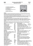
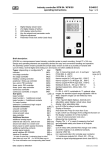
Industrial controller KFM 902 / 93
Operating instructions
1
1
2
3
4
5
6
- Page 1 of 2 -
2
Supply
LCD display for relay function
Descriptive text for displayed values
Digital value displays
Unit of display
Key for setpoint and parameter mode
Setpoint adjustment
B 902 E
Return
285
282
°
°
certifications: DIN, GL, BV
F92-lcd0710117
5
6
General:
KFM 902 is an industrial microcomputer-based controller series in control panel format 96 x 96 mm with a
performance range of up to 8 relay outputs, various signal inputs and outputs as well as numerous possible
optional extras. Communication with control systems is also possible.
All relay contacts are implemented as potential-free changeover contacts. Normally, the N.O. contacts of all
relays are internally permanently wired with RC elements. Optionally, the RC elements for relays K1…K3 are
led on terminals for the selective connection (N.O. contact factory-connected). The scope of delivery
includes plugable terminal blocks.
The transflective LCD indication with white background lighting is easy to read in both light and dark
environments. In operating mode up to 4 values (actual values, setpoint values, control settings, ..) can be
displayed including freely adjustable description text and unit of display. Additional displays for operating and
malfunction messages, including the corresponding hardware or custom display masks are optionally
available.
Stage controllers and three-point step controllers with auxiliary contact (e.g. burner controller) are fitted as
standard with a 2nd measuring input, continuous controllers have an extended measuring input range.
Types (depending on configuration):
Type
Measuring inputs:
Type suffix
Indicator
9020..
(max. 4, depending on version)
Pt100/standard signal, 0...400°C/adj.
without (or 0)
Single-stage controller
9021..
Pt100/standard signal, -200...+800°C/adj. 99mb14b
Two-stage controller
9022..
Thermal element NiCr-Ni (K)0...1200°C
Three-point controller
9023..
Fe-CuNi (J)0... 900°C, PtRh-Pt (S)0...1700°C
qt
Positioner / follow-up controller
9024..
Two-point PID controller
9025..
Remote resistance transmitter 0…100/1000:
qw
Three-point PID controller
9026..
Feature for meas. input 2 with equipment external setpoint:
Three-point step controller
9027..
Standard signal configurable to ext. setpoint value, the
Continuous controller
9028..
Pt100 input is extra usable
Continuous controller with 2 outputs
9029..
Ranges:
Sub-types:
suffix
Pt 100: 0..400°C (switching controllers), -200..+800°C
Basic function
00
(continuous controllers), switchable to °F,
Basic function + 1..8 additional contacts 01..08
standard signal: Display adjustable -999 to 9999,
Basic function double, triple, quadruple 20,30,40
setpoint range can be limited via menu
Logic output 0/24V max 40mA
..L
Binary inputs:
Function extensions:(*)
Max. 20 inputs, alt. for potential-free contacts or for
Difference controller
991d
ext. voltage 0 / 24V, for status messages (can
Limitation controller
991g
optionally be saved) or control functions.
Cascade controller
991k
Displays:
Program controller
991p
Max. 4-four-digit value displays with selectable
Ramp setpoint
991r
decimal point, each including adjustable descriptive
Malfunction modul
991s
text and unit of display, optional add. message texts,
Stage controller
991t
custom display masks, up to 8 displays for relay
Additional devices:(*)
functions.
Additional analog inputs
(99) a.
External setpoint incl. switching
(99) bwa. Outputs:
Up to 8 relays as setting outputs or additional contacts, with
Second setpoint incl. switching
(99) bwz.
potential-free changeover contacts, switching power 250V 2A
Binary inputs for special functions
(99) b..
incl. spark extinction (on the N.O. contact)
Further additional contacts
(99) f
up to 6 continuous outputs 0/4...20mA, 0/2...10V
Analog signal outputs
(99) o.
(load <= 500 :), as setting or signal output
Interface by external module for
up to 3 logic outputs 0/24V max. 40 mA, alternatively
Profibus, Modbus, Ethernet, ..
(99) s..
16 outputs open collector, max 24 V / 100 mA
*See also data sheets 99.. !
subject to alterations
902_ve.doc / 1110307
Industry controller type 902 / 93
Technical data
Characteristics: (parameters dep. on sub type:)
Adjustment on parameter level, code locked,
pre adjusted on customer´s demand.
Proportional band Xp: 0,1...999,9 %
Integral action time Tn: 0,0...999,9 min
Rate time Tv: 0,0...99,9 min
Sensitivity of response Xsh: 0,1...1,0 %
Travel time of the actuator Tm: 6...600 sec
Switching frequency cy: 2...120 sec
Function characteristics: direct / inverted
Switching interval SA (add. contacts): 0..100,0 K
Switching difference Sd: 0,1...100,0 K
Additional contact functions:
As switching interval above and below setpoint or
independent adjustable with own setpoint and
measuring input, switching function adjustable
(ref. to chapter additional switching contacts)
Installation dimensions:
B 902 E
- Page 2 of 2 -
stage controller (inverted)
K2
on
off
K1
Sd2
Sd1
SA2
actual value
SP
three- point- step- controller (inverted)
K1(+)
on
K2(-)
off
actual value
Sh
SP
continuous controller
single output
double output
100%
AP
0%
in..
di..
in
di
P
-100%
Y1
Y2
P1
SP
td td
SP
P2
..di
..in
l92-d4990419
Other data:
Housing for panel mounting, 96 x 96 mm
Power supply: 100..250 VAC, about 14 VA
alternative 24 V AC / DC
B +0,8
Protective system EN 60529: IP54 (terminals IP20)
+0,8
H
Permissible ambient temperature: 0...60°C
Nominal temperature: 20°C
Climatic category: KWF to EN 60529
Relative humidity <= 75 % yearly average,
Form 96x96: L=150mm, B=92mm, H=92mm
no condensation
EMC: referring to EN 61326
Wiring diagram: (Example, valid for each delivered controller is the wiring diagram on its casing only)
L
SPE
analog-, m easuring inputs
a99 +18V
a11
a1
*
a12
a
s
a2
a13 (-)
e
a3 (-)
ai1 a14 I
a4 I
a15 U
a5 U
a99 +18V
a99 +18V
a16
a6
*
a17
a
s
a7
a18 (-)
e
a8
ai2 a19 I
a9 I
a20 U
a10 U
SPE* a99 +18V
a0 (-)
a21
a22
(with Konf. SPE the
a23 (-)
Pt100 input of ai2 is
a24 I
additionally usable!) a25 U
a99 +18V
*= option
a26
a27
service
a28 (-)
interface
a29 I
KFM 2.0
a30 U
a
s
e
a
s
e
a
s
e
a
s
e
binary inputs
b99 (+) 24VDC
b0 (-) 0V
ai3 b1 Bin.1
b2 Bin.2
b3 Bin.3
b4 Bin.4
*
b5 Bin.5
b6 Bin.6
ai4 b7 Bin.7
b8 Bin.8
b9 Bin.9
b10 Bin.10
*
:
:
:
:
ai5 :
:
b17 Bin.17
b18 Bin.18
b19 Bin.19
*
b20 Bin.20
*
b0
b0
b21
b22
b23
b24
b25
b26
b27
b28
b29
b30
:
:
:
b37
b38
b39
b40
(-) 0V
(-) 0V
Bin.21
Bin.22
Bin.23
Bin.24
Bin.25
Bin.26
Bin.27
Bin.28
Bin.29
Bin.30
:
:
:
Bin.37
Bin.38
Bin.39
Bin.40
anal.-, logic outp. pow er supply, relays
35 (+) 0/24V
27 L+ (100..250V-type:
36 (-) logic out 1 28 L- internal fuse
37 (+) 0/24V
29
T 0,5 A )
36 (-) logic out 2 50a
62
38 (+) 0/24V
50
63
K5
K1 #
36 (-) logic out 3 51
64
30 (+) 0/4..20mA 52
65
31 (-) Y1
53a
66
K6
32 (+) 0/4..20mA 53
67
K2 #
31 (-) Y2
54
68
40 (+) 0/4..20mA 55
69
K7
31 (-) Sout 1
56a
70
41 (+) 0/4..20mA 56
71
K3 #
31 (-) Sout 2
57
72
K8
42 (+) 0/4..20mA 58
73
31 (-) Sout 3
59
74
43 (+) 0/4..20mA 60
K4
75
K9
31 (-) Sout 4
61
76
(Protect relay outp. by ext. fuse 2A)
ai6 with 2 binary input cards the
terminals b0 of each card
are linked (factory setting)
Optionally, RC element selective
connectable, see below,
N.O. contact factory-connected
#
Wiring, examples for input 1 and output 1 respectively:
Pt100
a1
a2 3-w ire
a3
a1
a2 2-w ire
a3
data subjects to alteration
standard signal
(-) a3
0/4..20mA
(+) a4
(-) a4 4..20mA
(+) a99 2-w ire-Tr.
(-) a3
0/2..10V
(+) a5
others
a1 thermoa2 couple
a
s
e
binary inputs
b99 pot.free
b1 contact
+
a1
feedback a2
device
a3
relay contact
actuator
50a w ithout RCup
50 element
50a N.O. contact
M
b1 external
50 w ith RC
dn
b0 voltage. 24V
50a N.C. contact
N
L
51 w ith RC
#
50a
50
51
52
53a
53
54
55
902_re.doc / 1110301