1
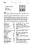
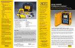
Industrial controller KFM 902 / 93
Operating instructions
1
1
2
3
4
5
6
LCD display for relay function
Descriptive text for displayed values
Digital value displays
Unit of display
Key for setpoint and parameter mode
Setpoint adjustment
B 902 E
- Page 1 -
2
Supply
Return
285
282
°
°
certifications: DIN, GL, BV
F92-lcd0710117
5
6
General:
KFM 902 is an industrial microcomputer-based controller series in control panel format 96 x 96 mm with a
performance range of up to 8 relay outputs, various signal inputs and outputs as well as numerous possible
optional extras. Communication with control systems is also possible.
All relay contacts are implemented as potential-free changeover contacts. Normally, the N.O. contacts of all
relays are internally permanently wired with RC elements. Optionally, the RC elements for relays K1…K3 are
led on terminals for the selective connection (N.O. contact factory-connected). The scope of delivery
includes plugable terminal blocks.
The transflective LCD indication with white background lighting is easy to read in both light and dark
environments. In operating mode up to 4 values (actual values, setpoint values, control settings, ..) can be
displayed including freely adjustable description text and unit of display. Additional displays for operating and
malfunction messages, including the corresponding hardware or custom display masks are optionally
available.
Stage controllers and three-point step controllers with auxiliary contact (e.g. burner controller) are fitted as
standard with a 2nd measuring input, continuous controllers have an extended measuring input range.
Types (depending on configuration):
Type
Measuring inputs:
Type suffix
Indicator
9020..
(max. 4, depending on version)
Pt100/standard signal, 0...400°C/adj.
without (or 0)
Single-stage controller
9021..
Pt100/standard signal, -200...+800°C/adj. 99mb14b
Two-stage controller
9022..
Thermal element NiCr-Ni (K)0...1200°C
Three-point controller
9023..
Fe-CuNi (J)0... 900°C, PtRh-Pt (S)0...1700°C
qt
Positioner / follow-up controller
9024..
Two-point PID controller
9025..
Remote resistance transmitter 0…100/1000:
qw
Three-point PID controller
9026..
Feature for meas. input 2 with equipment external setpoint:
Three-point step controller
9027..
Standard signal configurable to ext. setpoint value, the
Continuous controller
9028..
Pt100 input is extra usable
Continuous controller with 2 outputs
9029..
Ranges:
Sub-types:
suffix
Pt 100: 0..400°C (switching controllers), -200..+800°C
Basic function
00
(continuous controllers), switchable to °F,
Basic function + 1..8 additional contacts 01..08
standard signal: Display adjustable -999 to 9999,
Basic function double, triple, quadruple 20,30,40
setpoint range can be limited via menu
Logic output 0/24V max 40mA
..L
Binary inputs:
Function extensions:(*)
Max. 20 inputs, alt. for potential-free contacts or for
Difference controller
991d
ext. voltage 0 / 24V, for status messages (can
Limitation controller
991g
optionally be saved) or control functions.
Cascade controller
991k
Displays:
Program controller
991p
Max. 4-four-digit value displays with selectable
Ramp setpoint
991r
decimal point, each including adjustable descriptive
Malfunction modul
991s
text and unit of display, optional add. message texts,
Stage controller
991t
custom display masks, up to 8 displays for relay
Additional devices:(*)
functions.
Additional analog inputs
(99) a.
External setpoint incl. switching
(99) bwa. Outputs:
Up to 8 relays as setting outputs or additional contacts, with
Second setpoint incl. switching
(99) bwz.
potential-free changeover contacts, switching power 250V 2A
Binary inputs for special functions
(99) b..
incl. spark extinction (on the N.O. contact)
Further additional contacts
(99) f
up to 6 continuous outputs 0/4...20mA, 0/2...10V
Analog signal outputs
(99) o.
(load <= 500 :), as setting or signal output
Interface by external module for
up to 3 logic outputs 0/24V max. 40 mA, alternatively
Profibus, Modbus, Ethernet, ..
(99) s..
16 outputs open collector, max 24 V / 100 mA
*See also data sheets 99.. !
subject to alterations
902_e1.doc / 1110307
Industry controller type 9...
Installation and connection
B 9... E
- page 2 -
Installation:
Before installation inspect the controller for any visible signs of damage caused during transport.
Check power supply acc. to name plate.
Push the housing from the front into the DIN- panel cut-out and secure from behind with the
fastening devices supplied.
Electrical wiring:
Plug bar on the back face of the controller; connect up the controller at the rear following the
wiring diagram; wire cross section max. 1,5 mm2
- To avoid cross interference all low voltage measuring lines and pilot wires must be encased
in a shielded cable (the shielding must be earthed one-sided).
- The control leads must be fused externally to protect the output relays.
- Phase wire and neutral wire must not be transposed.
Putting into operation:
Switch on power supply. Digital display and control lamps (if available) will light up according to
the setpoint after some seconds. If nothing happens check the fine-wire fuse (if available) on
the back panel of the controller and the electrical wiring. Adjust set value and check other
adjustments.
Maintenance:
All electronic controllers in the product range of the manufacturer are virtually maintenance-free.
Provided that the controller is correctly installed and put into operation and is protected against
mechanical damage and inadmissible operating conditions, it should give years of trouble-free
service. In case of faults repair work by the customer should be restricted to the externally
accessible leads and connections and components the customer is expressly permitted to deal
with himself (bridge circuits, fuses).
All further work, especially on internal components will terminate warranty, makes subsequent
inspection and fault repair more difficult and can cause considerable damage to the circuitry.
For repair remittance remove plug board with connected leads on the rear side,
loosen fastening devices and remove controller from the panel.
In case of remittance please give precise details of the fault to reduce time and cost of repair.
Error messages:
Err 1...6
Err 55
Fault on measuring input nr. ...
check measuring lines for short circuit or breakage
check measuring input by connecting a RTD
Fault on loading the parameter;
press any key, the controller starts in emergency operation mode,
configuration of the parameters has to be checked
Err 50
Err 52
Hardware error in program section
Hardware error in data section
no further operation possible, remit controller for repair
Err 58
Err 59
Err 60
Err 61
Binary inputs out of function (status = 0), remit controller for repair
Digital outputs out of function (switched off), remit controller for repair
Relay outputs out of function (switched off), remit controller for repair
Analogue outputs out of function (0 %), remit controller for repair
Err 202
Err 205
Err 206
data subjects to alteration
Error messages during self adaptation:
Ambient conditions are not suitable for self adaptation;
adjust parameter manually
routine exceeded the setpoint
raise setpoint or lower actual value and start adaptation again
Fault on measuring input during adaptation;
check the wiring and start adaptation again
9_E2.DOC /0910527
Industrial controller type 902 / 93..
Operation
B 902 E
- Page 3 -
Operating status:
1
2
ACT.VAL.1
2 3 5. 8
°C
ACT.VAL.2
2 3 1. 2
°C
SETPOINT
2 3 6. 0
°C
ACT.VAL. 1
2 3 5. 8
°C
ACT.VAL.2
2 3 1. 2
°C
3
o
o
o
o
12:09
T EMP ERT URE
12:26
L EV E L
B I N. ME
WA T E R
S MOK E
ST EAM
PRESS U
BURNE R
BURNE R
CI RC. P
CI RC. P
S
L
G
T
R
SAG
EVE
AS
E MP
E L
OP E
MA X
U MP
U MP
H I GH
L OW
ES P1 / 2
L
L OW
T E MP H I GH
H I GH
I MI T T E R
RA T I ON
L OA D
ST EP 1
ST EP 2
Analog values: Depending on the configuration, up to three values in 10 mm size
or two values in 10 mm and two values in 3 mm size can be displayed. A dedicated
unit for each value can be configured if desired. The corresponding descriptive
texts are changeable by means of the PKS PC software.
Depending on equipment, the status of the relays is shown at the left side of the
display via the respective number (K) 1, 2, ..
In conjunction with the option of binary input messages, the corresponding texts
are shown in the two lower 3 mm display lines if the binary inputs are activated.
The corresponding value displays are hidden during this time.
- button (do not hold)
Message list: Briefly press the
The display now shows a list of message texts for all activated binary inputs in the
order of their occurrence. Additionally, messages which are configured to the
collective relay are marked with a circle symbol. This flashes until the message has
been confirmed by means of binary input 1.
Setpoint value setting:
Briefly press the
1
ACT.VAL.1
2 3 5. 8
°C
ACT.VAL.2
2 3 1. 2
°C
3
4
SP=236.0
SET PO INT CHAN NEL 1
SP
- button (do not hold)
A flashing frame with the description SP shows the activated setpoint level.
The upper text display shows the parameter name “SP=” and the adjusted value,
the lower text display optionally shows a description text.
The displayed value can now be changed using the (smaller) and (larger)
buttons.
A setpoint change is effective immediately, without any further operational steps.
‘Arrow’ button acceleration effect:
longer pressing causes faster changing.
return to operating mode:
- button (or automatic after > 30 sec)
briefly press the
optional:
*SPB
*SP
SP2 / 3 / ..
SPE
SP-F
Briefly press the
- button again each time:
Bus setpoint, forced by an external bus adapter (e.g. 99spde..)
setpoints of additional control loops (*=no)
additional setpoints for the control loops
external setpoint (display only);
flashing description signifies for this version:
value is presently not active.
Switch over menu SP / SPE (only in case of adjustment SP-F=MENU (Conf-level))
Manual operation: (optional)
Press and hold the -button, then additionally press the - button, then release
both. (Option: Switch on and off using the extra button )
(For multi-channel controllers, first select the channel number CH..
using the ... . buttons and continue with the
-button, after which:)
MAN.
The upper text display shows “MAN. *", plus the setting variable, if it exists.
The control function is switched off.
Manual control is now possible using the ... . buttons
return to operating mode: only with
-button (or. ),
no automatic switching back from manual operation!
Optional: Start self-optimisation (see chapter Optimisation):
press the
-button >5 sec whilst in manual control function;
the lower display jumps to "-Ad-".
Abort: press the
-button again >5 sec
subject to alterations
902_e3.DOC / 1010419
Industrial controller type 902 / 93..
Parameter setting
B 902 E
- Page 4 -
Access from the operating level
1
ACT.VAL.1
2 3 5. 8
°C
ACT.VAL.2
2 3 1. 2
°C
3
4
COD2 = 0
PAR1
CODE NUMBER 2
After polling (see instructions for level PARA 1 / 2), a flashing frame with the
description PAR1 / PAR2 shows the activated parameter level.
The upper text display shows the first parameter name and the adjusted value,
the lower text display optionally shows a description text.
continue to the next parameter and/or confirm entry:
- button
briefly press each time the
To change the setting displayed: Press the
...
buttons
Settings in detail:
(existence depends on version and type):
PARA 1
- button >5 sec,
Polling: press and hold the
release it after the display reacts.
COD2
CH..
P
I
D
SH
SA.
SP.
SD.
Code number 2 (password) for parameter levels (1…9999)
1
(only) for multi-channel controllers: Selection of desired channel (no.)
Proportional range Xp (%) (for more details, see “Optimisation”)
25.0
Integral action time Tn (min) (for more details, see “Optimisation”) 7.0
Rate time Tv (min) (for more details, see “Optimisation”)
0.2
Response sensitivity (“dead zone”) Xsh (%)
0.1
Setpoint distance (absolute) for following switching contact no.
5.0*
Independent setpoint for switching contact no.
0.0
Hysteresis (switching difference on/off) for switching contact no.
3.0
(*..201,701/SA3 :10.0)
return to operating mode:
- button (or automatic after > 30 sec)
briefly press the
PARA 2
- button, additionally press the
- button,
Polling: press and hold the
hold both buttons for >5 sec, release them after the display reacts:
COD2
Unit
*BLO/*BHI
*ELO/*EHI
*SLO/*SHI
NST
*Lo / *HI
CRST
DSP1
DSP2
DSP3
Code number 2 (password) for parameter levels (1…9999)
1
Switches the unit of display (°C / °F)
C
(only) for voltage / current input: start / end of display range
#
(only) for external setpoint: start / end of setpoint range
#
(only) for information signal output: start / end of range
#
Number of decimal places of the display (0 / 1 / 2, depending on range) 0
Setpoint setting range, lower / upper limit
#
Contrast setting for display (0…20)
32
Variable shown in first display line (10mm) (OFF / SP / Y / IST..)
IST1
Variable shown in second display line (10mm) (OFF / SP / Y / IST..)
IST2
Variable shown in third display line (10mm if DSP4=OFF, otherwise 3mm)
(OFF / SP / Y / IST..)
SP
Variable shown in fourth display line (3mm) (OFF / SP / Y / IST..)
OFF
(SP = setpoint, Y=setting variable, Ist * = Actual value channel / measuring input*)
Unit of measurement for corresponding display line(°C / °F / % / bar /
mbar / mPas / cSt / Kgm3 / mm / KPa / L / m3/h) Note: no conversion! C
Desription text for corresponding display line1..4: choose from a 1= ACT.VAL1
predefined list (ACT.VAL..,SETPOINT, SUPPLY,RETURN),
2= ACT.VAL1
resp. 1 additionally editable text.. ,changeable by PKS-software 3= SETPOINT
DSP4
EIN1..4
Text1/2/3/4
Factory setting
Notes
___
___
___
___
___
___
___
___
___
___
___
___
___
___
___
___
___
___
___
___
___
___
___
___
return to operating mode:
- button (or automatic after > 30 sec)
briefly press the
subject to alterations
902_e4.doc / 1110125
Industry controller type 9..
Optimization
B 9... E
- page 5 -
1. manual optimization
An optimum adaptation of the control parameters (P,I,D) is necessary in order to balance
an appearing deviation as quickly, non-oscillating and exactly as possible,
according to the given operating conditions.
Generally these adjustments require a lot of professional knowledge that cannot be replaced
by this brief information.
The following informations are for help purpose only:
P = proportional band Xp (%):
lower value = longer impulses, more sensitive reaction
higher value = shorter impulses, less sensitive reaction
Examples: - Oscillating temperature without distinct initial overshot: Xp too low;
- The setpoint is reached very slowly after initial exceeding: Xp too high.
I = integral action time Tn (min):
lower value= shorter impulse gaps, faster balancing
higher value= longer impulse gaps, slower balancing
Examples: - the set value is reached very slowly without overshooting: Tn too high;
- high initial overshot followed by fading oscillation: Tn too low.
D = rate time Tv (min):
increases the controller reaction in case of fast actual value or setpoint alterations
(adjust only if necessary). Higher values cause higher increase.
2. Self-adaptation
The self-adaptation is an automatic procedure that determines and self-adjusts
the optimum control parameters Xp, Tn and Tv.
Operation, if contained in supply schedule:
(Parameter-safety-switch on the rear panel of the controller (if available) has to be unlocked:
position "u")
Check starting assumptions:
Actual value at least 20% below the adjusted set value,(e.g.:heating phase), otherwise first:
Lower actual value adequately by manual operation (position of final control element) (quick circuits)
or increase setpoint adequately, if admissible. (faster procedure for slower circuits)
- key (optional: seperate key).
Call manual operation level: Press - key plus
Check controller output: must not be higher than 85% , reduce if necessary.
- key for more than 5 sec. on manual operation level.
Start self-adaptation: Hold down
During operation the lower display shows: "-Ad-",
the upper display still shows permanently the actual value.
Information about computer operation: First the self-adaptation program waits for stabilization
of the actual value according to the given controller output (actual value alteration < 0,1% / min),
then it increases the output signal about 10% or, in case of three- point- step controller operation,
it triggers an output impulse with about 10% of the adjusted regulating time.
The optimum parameters are computed according to the unit- step response.
Cancel: Press
- key for more than 5 sec. = return to manual operation level
After successfully finishing the procedure the controller will return automatically
to operating level.
Unsuccessful adaptation ( Display shows error code, ref.to chapter error messages):
- key again: Return to manual operation level
Press
eliminate the indicated error
start adaptation again:
- key > 5 sec.
or return to operating level:
- key shortly
data subjects to alteration
9_E5.DOC / 0810331
Industrial controller type 902 / 93
Configuration
B 902 E
- Page 6 -
Access from the operating level
1
ACT.VAL.1
2 3 5. 8
ACT.VAL.2
2 3 1. 2
3
4
°C
°C
CONF
CODE = 1
CODE NUMBER
Polling: press and hold the
- button, additionally press the
- button,
hold both buttons for >5 sec, release them after the display reacts:
A flashing frame with the description CONF shows the activated parameter
level. The upper text display shows the first parameter name and the
adjusted value, the lower text display optionally shows a description text.
continue to the next parameter and/or confirm entry:
- button
briefly press each time the
To change the setting displayed:
Number values: Press the
... buttons, text values:press the
Settings in detail:
(existence depends on version and type):
CODE
COD1
COD2
LNG
CONF
- button
Factory setting
Notes
Code number for configuration level (1…9999),
1
Alternatively: Hold the
button for more than 10 sec after code entry:
Possibility of setting the code number for the configuration level(option).1
Possibility of setting the code number for the parameter levels(option). 1
Language selection of the menu text(Deutsch,English,User def, Off)Deutsch
Selection of the configured controller function (if existent)
return to operating mode: Briefly press the
___
___
___
___
- button
or: continue to the following settings: press the
-button and hold it > 5 sec:
Note: when continuing after changing a function, the display first flashes for a
few seconds, only then does the desired switching over or back take place
Configuration external/second setpoint “BIN” (activation by binary input)
/ “MENU” (activation from the setpoint level) / “SP2” / “AUS”=OFF
MENU
Input type for input no.*: "RTD / 0-20 / 4-20(mA) / 0-10 / 2-10(V) /
RTD
AUS=OFF" (note different terminals for I/U!)**
Correction value for changing the controller display (+/-)
0.0
Type of effect of second / external setpoint: "Add/ Sub/ AbS"
AbS
(adding / subtracting / absolute value)
Setting time of the controlled drive “6…600” (sec)
60 sec
Switching frequency in two-point controllers: "2...120" (sec.)
20 sec
Setting output signal "0...20 / 4...20" (mA) /0...10 / 2...10 (V)“
4...20 mA
Setting output characteristic: direct / inverse "di / in"
in
(with 2 outputs: "in in / in di / di in / di di")
inin
For 2 outputs: dead zone between outputs 1 and 2 “0…10%”
0
Output signal working point (-100…+100)
50
Automatic adjustment of remote transmitter input (see extra sheet 99ar)
Assignment of inform. output signal(s)* (act. value/setp., setting var..) Ist1
Type of information output signal(s)* “0..20/4..20(mA)/0..10/2..10(V)” 4...20 mA
(* Sout= Signal 1; Sou2 = Signal 2)
Behaviour of the setting output in the event of measurement line error:
Relay position: "rel1 / rel2 / OFF"
rel2(70.),rel1(20.)
Continuous output: "0...100" (%)
0
___
___
BIN*
BIN*
BIN*
Sub-menu for binary input configurations
-button and hold it > 5 sec:
Polling: press the
Direction of control action binary input* direct / inverse (di/in)
Assignment of collective relay: Stat=none, SREL= collective relay
Switch-on delay (0…300 sec)
di
stat
0
___
___
___
REL*
REL*
REL*
Adr
BAUD
Function mode of additional contact (relay no.)
Measuring input / control loop assigned to additional contact
Add. contact – relay pos. in event of meas. line error "SiE/SiA"(on/off)
if equipped with interface: bus address (number)
if equipped with interface: baudrate (9600/19200/38400)
SoA(701),StA(201)___
Ist 1
___
Si A
___
5
___
38400
___
SPEF
AIN*
IST*
SP 2/E
*YM
*CY' '
*OUT
*OUT
*td
*AP
FG A/E
Sou*
Sou*
*Y_S
bin. Eing
return to operating mode: briefly press the
___
___
___
___
___
___
___
___
___
___
___
___
___
- button again
* = ID number in case of several inputs / outputs or control loops.
**= Rtd input of ain2 is additionally usable if equipped with ext. setpoint and activation using SP-F.
subject to alterations
902_e6.doc / 1110125
Industrial controller type 9..
Facilities for Setting Supplementary Contacts
B 9... E
- page 7 -
Selectable switching functions (depending on version):
For setting please refer to configuration level under „reL...“
Switching functions for trailing contacts:
on
Break contact on either side of setpoint
(Limit comparator). Relay drops out as
deviation increases (Aus = off)
off
Make contact on either side of setpoint
(Limit comparator). Relay picks up as
deviation increases (Ein = on)
off
Su A
Break contact below setpoint. Relay drops
out as actual value decreases (Aus = off)
off
Su E
Make contact below setpoint. Relay picks
up as actual value decreases (Ein = on)
LC A
LC E
So A
So E
St A
SA
SA
Sd
on
Sd
SA
SA
Sd
on
Sd
SA
on
off
Break contact above setpoint. Relay drops
out as actual value increases (Aus = off)
on
Make contact above setpoint. Relay picks
up as actual value increases (Ein = on)
on
Heating stage below setpoint. Relay
drops out actual value increases (Aus =
off)
Sd
Sd
SA
off
SA
off
SA
Sd
Sd
on
off
Sd
SA
actual value
SP
(setpoint)
Switching functions for independent contacts:
on
US A
Relay drops out with increasing actual
value (Aus = off)
off
US E
Relay picks up with increasing actual
value (Ein = on)
Sd
on
off
Service function:
Sd
actual value
SP
Switching point
Ein/Aus contact is constantly switched on (Ein) or
off (Aus) respectively
Special function:
SF6
as SoA but switching point at setpoint, control output around SA below
In each case additional settings follow under "rEL." after the selection is acknowledged (P key)
(depending on version):
Ist./ Y
assigned value: actual value no. ... or Y (actuating signal)
CH../.SP.(only) for trailing contacts: assigned control circuit / channel (no.) or
assigned setpoint (1SP., rSP, SP.1, ..)
for independent contacts: assignment of parameter input (channel no..)
SI E
SI A
"Safety" shut down (in case of measuring line fault):
Relay for "Safety" behaviour in event of measuring circuit error: relay on
Relay for "Safety" behaviour in event of measuring circuit error: relay off
Subject to technical changes
9_E7.DOC / 1110125
Industry controller type 902 / 93
Technical data
Characteristics: (parameters dep. on sub type:)
Adjustment on parameter level, code locked,
pre adjusted on customer´s demand.
Proportional band Xp: 0,1...999,9 %
Integral action time Tn: 0,0...999,9 min
Rate time Tv: 0,0...99,9 min
Sensitivity of response Xsh: 0,1...1,0 %
Travel time of the actuator Tm: 6...600 sec
Switching frequency cy: 2...120 sec
Function characteristics: direct / inverted
Switching interval SA (add. contacts): 0..100,0 K
Switching difference Sd: 0,1...100,0 K
Additional contact functions:
As switching interval above and below setpoint or
independent adjustable with own setpoint and
measuring input, switching function adjustable
(ref. to chapter additional switching contacts)
Installation dimensions:
B 902 E
- Page 8 -
stage controller (inverted)
K2
on
off
K1
Sd2
Sd1
SA2
actual value
SP
three- point- step- controller (inverted)
K1(+)
on
K2(-)
off
actual value
Sh
SP
continuous controller
single output
double output
100%
AP
0%
in..
di..
in
di
P
-100%
Y1
Y2
P1
SP
td td
SP
P2
..di
..in
l92-d4990419
Other data:
Housing for panel mounting, 96 x 96 mm
Power supply: 100..250 VAC, about 14 VA
alternative 24 V AC / DC
B +0,8
Protective system EN 60529: IP54 (terminals IP20)
H +0,8
Permissible ambient temperature: 0...60°C
Nominal temperature: 20°C
Climatic category: KWF to EN 60529
Relative humidity <= 75 % yearly average,
Form 96x96: L=150mm, B=92mm, H=92mm
no condensation
EMC: referring to EN 61326
Wiring diagram: (Example, valid for each delivered controller is the wiring diagram on its casing only)
L
SPE
analog-, m easuring inputs
a99 +18V
a11
a1
*
a12
a
s
a2
a13 (-)
e
a3 (-)
ai1 a14 I
a4 I
a15 U
a5 U
a99 +18V
a99 +18V
a16
a6
*
a17
a
s
a7
a18 (-)
e
a8
ai2 a19 I
a9 I
a20 U
a10 U
SPE* a99 +18V
a0 (-)
a21
a22
(with Konf. SPE the
a23 (-)
Pt100 input of ai2 is
a24 I
additionally usable!) a25 U
a99 +18V
*= option
a26
a27
service
a28 (-)
interface
a29 I
KFM 2.0
a30 U
a
s
e
a
s
e
a
s
e
a
s
e
binary inputs
b99 (+) 24VDC
b0 (-) 0V
ai3 b1 Bin.1
b2 Bin.2
b3 Bin.3
b4 Bin.4
*
b5 Bin.5
b6 Bin.6
ai4 b7 Bin.7
b8 Bin.8
b9 Bin.9
b10 Bin.10
*
:
:
:
:
ai5 :
:
b17 Bin.17
b18 Bin.18
b19 Bin.19
*
b20 Bin.20
*
b0
b0
b21
b22
b23
b24
b25
b26
b27
b28
b29
b30
:
:
:
b37
b38
b39
b40
(-) 0V
(-) 0V
Bin.21
Bin.22
Bin.23
Bin.24
Bin.25
Bin.26
Bin.27
Bin.28
Bin.29
Bin.30
:
:
:
Bin.37
Bin.38
Bin.39
Bin.40
anal.-, logic outp. pow er supply, relays
35 (+) 0/24V
27 L+ (100..250V-type:
36 (-) logic out 1 28 L- internal fuse
37 (+) 0/24V
29
T 0,5 A )
36 (-) logic out 2 50a
62
38 (+) 0/24V
50
63
K5
K1 #
36 (-) logic out 3 51
64
30 (+) 0/4..20mA 52
65
31 (-) Y1
53a
66
K6
32 (+) 0/4..20mA 53
67
K2 #
31 (-) Y2
54
68
40 (+) 0/4..20mA 55
69
K7
31 (-) Sout 1
56a
70
41 (+) 0/4..20mA 56
71
K3 #
31 (-) Sout 2
57
72
K8
42 (+) 0/4..20mA 58
73
31 (-) Sout 3
59
74
43 (+) 0/4..20mA 60
K4
75
K9
31 (-) Sout 4
61
76
(Protect relay outp. by ext. fuse 2A)
ai6 with 2 binary input cards the
terminals b0 of each card
are linked (factory setting)
Optionally, RC element selective
connectable, see below,
N.O. contact factory-connected
#
Wiring, examples for input 1 and output 1 respectively:
Pt100
a1
a2 3-w ire
a3
a1
a2 2-w ire
a3
data subjects to alteration
standard signal
(-) a3
0/4..20mA
(+) a4
(-) a4 4..20mA
(+) a99 2-w ire-Tr.
(-) a3
0/2..10V
(+) a5
others
a1 thermoa2 couple
a
s
e
binary inputs
b99 pot.free
b1 contact
+
a1
feedback a2
device
a3
#
relay contact
actuator
50a w ithout RCup
50 element
50a N.O. contact
M
b1 external
50 w ith RC
dn
b0 voltage. 24V
50a N.C. contact
N
L
51 w ith RC
50a
50
51
52
53a
53
54
55
902_e8.doc / 1110125