1
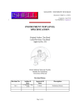
iSense GPS Module User Guide
coalesenses
research to innovate
Coalesenses GmbH
Maria-Goeppert-Str. 1
23562 Lübeck
Germany www.coalesenses.com
[email protected]
iSense GPS Module User Guide
Document history
Version
Date
Changes
1.0
12.05.2009
Initial version
coalesenses
research to innovate
2 / 27
iSense GPS Module User Guide
Contents
1.
About this User Guide .................................................................................................................... 4
2.
General Description ........................................................................................................................ 5
3.
4.
5.
2.1.
Handling and Security Instructions .......................................................................................... 6
2.2.
Mounting the CPG Module on an iSense Module Stack ......................................................... 7
2.3.
GPS Module Fix Indicator LED .............................................................................................. 9
GpsModule API Description ........................................................................................................ 10
3.1.
Constructor............................................................................................................................. 10
3.2.
Destructor............................................................................................................................... 11
3.3.
enable ..................................................................................................................................... 11
3.4.
disable .................................................................................................................................... 11
3.5.
enabled ................................................................................................................................... 12
3.6.
satellites.................................................................................................................................. 12
3.7.
fix_state .................................................................................................................................. 13
3.8.
PositionHandler interface....................................................................................................... 13
GPS Module Demo Application ................................................................................................... 15
4.1.
Obtaining the GPS Module Demo Application ..................................................................... 15
4.2.
Compiling the GPS Module Demo Application .................................................................... 15
4.2.1.
Using Eclipse ............................................................................................................... 15
4.2.2.
Using the Command Line ............................................................................................ 18
4.3.
GPS Module Demo Application functionality ....................................................................... 19
4.4.
Flashing the GPS Module Demo Application........................................................................ 23
References .................................................................................................................................... 26
coalesenses
research to innovate
3 / 27
iSense GPS Module User Guide
1. About this User Guide
In this user guide,
•
files and folders are represented in the Arial typeface,
•
code fragments, function names etc. are represented in the Courier New typeface,
•
GUI elements such as button descriptions etc. are represented in “quotation marks”,
•
titles of other documents are presented in Italic type.
This manual assumes that the reader has successfully installed the iSense development environment,
and obtained the iSense standard firmware. For further information on theses steps, consult the
Development Environment Setup User Guide [1].
In addition, it is assumed that the user is familiar with the use of iShell. For further information on
iShell, consult the iShell User Guide [2].
For further information on iSense firmware programming concepts and on application development, it
is recommended to read the Writing iSense Applications User Guide [3].
coalesenses
research to innovate
4 / 27
iSense GPS Module User Guide
2. General Description
The iSense GPS Module supplies position information to iSense sensor nodes in all outdoor
deployments. Like this, nodes equipped with the this module can not only serve as anchors for location
protocols, but can also provide continuous location updates for mobiles sensor nodes
The iSense GPS Module is based on the SiRF Star 3 chipset. Due to its 200,000 correlators and 20
channel support it is known for its outstanding accuracy and sensitivity. It is capable of SBAS
(WAAS, EGNOS, MSAS), and combines low power consumption with extremely fast fixing times.
The module features a high-performance patch antenna, a build-in micro battery to preserve system
data for rapid satellite acquisition and an LED for GPS fix indication.
The GPS Module can be switched on and off by an iSense Core Module via an API call (see Section
3.3 and Section 3.4).
coalesenses
research to innovate
5 / 27
iSense GPS Module User Guide
With the 34 pin connector (X2) on the top side, the GPS Module can be connected to other iSense
modules such as the iSense Core Module.
2.1. Handling and Security Instructions
Note that all iSense Modules are sensitive to electro-static discharge. Appropriate protection measures
have to be taken.
If not protected by an appropriate housing, all iSense components must be protected from humidity,
mechanical impact, and short circuiting by contact with conductive materials.
Note that all cable plugs and headers are designed to be extremely compact, and are not intended for
frequent plugging and unplugging. Never pull the cables to remove the plugs from the corresponding
modules, always pull the plug itself. If required, use an appropriate tool (or the pulling cord if
available). Even though all plugs/headers are coded, be sure to pay attention to the proper orientation.
Never apply force. Never use cables if their insulation is damaged.
Note that iSense modules are not intended for hot-plugging, (dis-)connecting modules from or to other
modules in operation can result in a reset of the Core Module and other undesired effects.
All delivered components are intended for use in research application. For using these components
within other application domains, consult coalesenses prior to use.
Coalesenses products are not intended for use in life support systems, appliances or systems where
malfunction of these products can reasonably be expected to result in personal injury, death or severe
property or environmental damage. Coalesenses customers using or selling these products for use in
such applications do so at their own risk and agree to fully indemnify coalesenses for any damages
resulting from such use.
Do not connect components or devices to any iSense component that are not manufactured or
distributed by coalesenses without prior consultation of coalesenses. Note that doing so regardless of
consultation will void the warranty and the declaration of CE conformity. Coalesenses customers
connecting third party devices do so at their own risk and agree to fully indemnify coalesenses for any
damages or injury resulting from such use.
coalesenses
research to innovate
6 / 27
iSense GPS Module User Guide
2.2. Mounting the CPG Module on an iSense Module Stack
The iSense GPS Module consists of two parts, the GPS engine board and the holder board which it is
mounted onto with three screws.
In order to mount the GPS Module onto a stack of other iSense Modules and to fix it with both stack
mounting screws, you have to unmount the GPS engine board from the holder board. To do so, loosen
the three screws that attach the GPS engine board to the holder board.
coalesenses
research to innovate
7 / 27
iSense GPS Module User Guide
Use M2 x 8 mm spacers between the top iSense Module and the GPS holder board (A).
B
A
When mounting the iSense GPS holder module onto an iSense module stack, be sure that the stack
mounting screw/bolt does not get into mechanical contact with the GPS engine board. To ensure this,
make sure that the stack mounting screw/bolt does not stand out of the holder module more than 2mm
(B) before you remount the GPS engine board onto the holder module. Screw together the iSense
module stack.
B
Finally, remount the GPS engine board onto the holder board.
coalesenses
research to innovate
8 / 27
iSense GPS Module User Guide
2.3. GPS Module Fix Indicator LED
The iSense GPS Module features a LED (C) that indicates the module’s position fix state according to
the table below.
LED activity
GPS state
off
module not active
flashing fast
no fix available
flashing once per second
position fix available
C
coalesenses
research to innovate
9 / 27
iSense GPS Module User Guide
3. GpsModule API Description
The GpsModule class in the isense namespace contains all software functionality for operating the
CPS Module-specific features, including
•
switching the GPS Module on and off,
•
registering for position fix information,
•
reading out additional information such as fix state or satellite count.
The GpsModule class is defined in src/isense/modules/gps_module/gps_module.h in the
iSense directory.
The iSense firmware is structured into a large number of software modules that can be (de-)activated
separately. The below API description for each function specifies the required modules that must be
activated to use the functions, and names both the web compilation module name as well as the
according code define. An asterisk (*) indicates that the respective module is activated in the iSense
standard firmware.
The API description also indicates the make targets for which the different functions are available.
3.1. Constructor
GpsModule::GpsModule(Os &os, PositionHandler* ph);
Description:
Initializes the GpsModule class. By default, the module is switched off. After the module is
enabled, ph.handle_position(...) will be called upon position fix. For details on the
PositionHandler, please refer to Section 3.8.
Parameters:
os
Reference to the operating system class Os
ph
Reference the PositionHandler that shall be called upon a position fix. See
Section 3.8 for details.
Required modules:
GPS Module*
#define ISENSE_ENABLE_GPS_MODULE
GPS Time Fixing*
#define ISENSE_ENABLE_GPS_TIME
Available for the targets:
JN5139R, JN5139R1
coalesenses
research to innovate
10 / 27
iSense GPS Module User Guide
3.2. Destructor
GpsModule::~GpsModule();
Description:
Disabled the GPS Module in case it was switched on.
Parameters:
none
Required modules:
GPS Module*
#define ISENSE_ENABLE_GPS_MODULE
Available for the targets:
JN5139R, JN5139R1
3.3. enable
bool GpsModule::enable();
Description:
Enables the GPS Module (if it is disabled). Enabling the GPS Module prevents the sensor node
from going to sleep.
Parameters:
none
Returns:
true if the GPS Module was disabled before and is now enabled, false if the module was
already enabled before
Required modules:
GPS Module*
#define ISENSE_ENABLE_GPS_MODULE
Available for the targets:
JN5139R, JN5139R1
3.4. disable
void GpsModule::disable();
Description:
Disables the GPS Module (if it is ebabled).
Parameters:
coalesenses
research to innovate
11 / 27
iSense GPS Module User Guide
none
Required modules:
GPS Module*
#define ISENSE_ENABLE_GPS_MODULE
Available for the targets:
JN5139R, JN5139R1
3.5. enabled
bool GpsModule::enabled();
Description:
Return the activity state of the GPS Module.
Parameters:
none
Returns:
true if the GPS Module is enabled, false otherwise
Required modules:
GPS Module*
#define ISENSE_ENABLE_GPS_MODULE
Available for the targets:
JN5139R, JN5139R1
3.6. satellites
bool GpsModule::satellites();
Description:
Returns the number of satellites used for the last position fix.
Parameters:
none
Returns:
Number of satellites, or ISENSE_IVALID if the last fix was invalid or the GPS Module is
disabled
Required modules:
GPS Module*
#define ISENSE_ENABLE_GPS_MODULE
Available for the targets:
JN5139R, JN5139R1
coalesenses
research to innovate
12 / 27
iSense GPS Module User Guide
3.7. fix_state
FixState GpsModule::fix_state();
Description:
Returns the fix state of the last position fix.
Parameters:
none
Returns:
ISENSE_GPS_FIX_STATE_INVALID
Fix not available or invalid, or the GPS Module is disabled
ISENSE_GPS_FIX_STATE_GPS
GPS SPS Mode, fix valid
ISENSE_GPS_FIX_STATE_DGPS
Differential GPS, SPS Mode, fix valid
ISENSE_GPS_FIX_STATE_DEAD_RECKONING
Dead Reckoning Mode, fix valid
Required modules:
#define ISENSE_ENABLE_GPS_MODULE
GPS Module*
Available for the targets:
JN5139R, JN5139R1
3.8. PositionHandler interface
virtual void PositionHandler::handle_position(
uint8 latitude_degrees,
uint8 latitude_minutes,
uint16 latitude_frac,
DirectionIndicator lat_ind,
uint8 longitude_degrees,
uint8 longitude_minutes,
uint16 longitude_frac,
DirectionIndicator long_ind,
Time time
) = 0;
Description:
In order to be called upon position fixes, a class must inherit from PositionHandler and
has to overwrite the pure virtual handle_position method.
coalesenses
research to innovate
13 / 27
iSense GPS Module User Guide
After the GPS Module is enabled, handle_position(...) will be called upon position
fix. The passed time will be the current UTC time if the “GPS Time Fixing” module is enabled
in the firmware, or INVALID_TIME otherwise.
Parameters:
latitude_degrees
latitude degrees (0...90)
latitude_minutes
latitude minutes (0...59)
latitude_fraction
fraction of latitude minutes (given in ten thousands)
lat_ind
latitude indicator (northern or southern hemisphere):
ISENSE_GPS_LATITUDE_NORTH northern hemisphere
ISENSE_GPS_LATITUDE_SOUTH southern hemisphere
longitude_degrees
longitude degrees (0...180)
longitude_minutes
longitude minutes (0...59)
longitude_fraction fraction of longitudes minutes (given in ten thousands)
lat_ind
longitude indicator (western or eastern hemisphere):
ISENSE_GPS_LONGITUDE_WEST western hemisphere
ISENSE_GPS_LONGITUDE_EAST eastern hemisphere
time
UTC time. Only works if the GPS time fixing functionality
(ISENSE_ENABLE_GPS_TIME) is enabled. If so, a millisecond
precision UTC time is passed. Otherwise, INVALID_TIME is
passed.
Required modules:
GPS Module*
#define ISENSE_ENABLE_GPS_MODULE
GPS Time Fixing*
#define ISENSE_ENABLE_GPS_TIME
Available for the targets:
JN5139R, JN5139R1
coalesenses
research to innovate
14 / 27
iSense GPS Module User Guide
4. GPS Module Demo Application
The GPS Module demo application exemplifies how an application can make use of the GpsModule
API. It shows how to
•
register as a PositionHandler,
•
switching the GPS Module on,
•
deal with position fixes,
•
query the number of satellites.
4.1. Obtaining the GPS Module Demo Application
Go to coalesenses web site, click on “Downloads”, and then on “iSense Hardware”. In the “GPS
Module” section, click on the icon at the right in the “GPS Module Demo Application” row, and
download GpsModuleDemoApplication.zip.
Extract the content of GpsModuleDemoApplication.zip to the iApps directory.
4.2. Compiling the GPS Module Demo Application
The next step is compiling the GPS Module Demo Application.
4.2.1.
Using Eclipse
If you want to use Eclipse for compiling the GPS Module Demo Application, open Eclipse, and
change to the “C++” perspective.
You can now import the application into Eclipse. Choose “File” “Import” from the menu bar to
open the “Import” dialog.
coalesenses
research to innovate
15 / 27
iSense GPS Module User Guide
Choose “Existing projects into workspace”, and click on “Next”.
Click on the “Browse…”, and select the directory of the GPS Module demo application, i.e.
GpsModuleDemoApplication in the iApps directory.
coalesenses
research to innovate
16 / 27
iSense GPS Module User Guide
After doing do, the “GpsModuleDemoApplication” project should appear in the projects list of the
“Import” dialog.
If it doesn’t, the typical reason is that there is already a project called “GpsModuleDemoApplication”
in Eclipse, i.e.
•
you imported the GpsModuleDemoApplication before or
•
you created or imported a project with the same name before.
Be sure not to check “Copy projects into workspace” in the above dialog. Finish the import by clicking
on the “Finish” button.
As a result, you will find the “GpsModuleDemoApplication” project in the “Project Explorer”.
coalesenses
research to innovate
17 / 27
iSense GPS Module User Guide
In addition, the “GpsModuleDemoApplication” will appear in the “Make Targets” view. Double click
on “all” to build the demo application for all targets.
As a result, the “Console” view displays the compiler output during the build process. After that, it
should look similar to the output depicted below.
4.2.2.
Using the Command Line
If you want to use the command line tools for building the GPS Module Demo Application, open a
console window, change to the GpsModuleDemoApplication directory in your iApps directory, and
type “make”.
coalesenses
research to innovate
18 / 27
iSense GPS Module User Guide
After the build finished, the console output should look similar as shown above.
4.3. GPS Module Demo Application functionality
The
source
file
of
the
GPS
Module
demo
application
is
located
at
GpsModuleDemoApplication/src/GpsModuleDemoApplication.cpp.
The
class
GpsModuleDemoApplication is derived from isense::Application, and additionally
inherits from isense::PositionHandler.
class GpsModuleDemoApplication :
public Application,
public PositionHandler
{
public:
GpsModuleDemoApplication(Os &os);
// inherited from application, called upon device boot
void boot();
// inherited from isense::PositionHandler, called upon GPS Module
position fix
virtual void handle_position( uint8 latitude_degrees,
uint8 latitude_minutes,
uint16 latitude_frac,
DirectionIndicator lat_ind,
uint8 longitude_degrees,
uint8 longitude_minutes,
uint16 longitude_frac,
DirectionIndicator long_ind,
Time time );
private:
GpsModule* gps_;
};
GpsModuleDemoApplication overwrites isense::Application::boot(), which is
called upon the start up of the iSense sensor node.
coalesenses
research to innovate
19 / 27
iSense GPS Module User Guide
void
GpsModuleDemoApplication::
boot ()
{
//output a boot notification via a potentially connected Gateway Module
os().debug("App::Booting GPS Demo Application");
// allocate a GpsModule instance, pass this application as
// PositionHandler
gps_ = new GpsModule(os(), this);
// if allocation was successful
if (gps_!= NULL)
{
// enable GPS Module
gps_->enable();
// set logging mode to "Radio only"
os().set_log_mode(ISENSE_LOG_MODE_RADIO);
}
else // output error message via a potentially connected Gateway Module
os().fatal("Could not allocate GpsModule");
}
Within the boot() method, a GpsModule object is created, and a reference to the operating system
and a pointer to the application is are passed to the constructor. Like this, the application is registered
at the GpsModule as the PositionHandler. This is possible because the application implements
the pure virtual method from isense::PositionHandler (see Section 3.8).
If the allocation was successful, the GPS Module is enabled. This will start the position acquisition.
Note that while the GPS Module is enabled, the sensor node is prevented from going to the sleep
mode, because receiving position updates from the GPS Modules requires the node to be awake. As
soon as the GPS Module is disabled again, the node can go to sleep again (unless other components
prevent sleep, too).
After that, the log mode of the operating system is set the “Radio only” (no option but
ISENSE_LOG_MODE_RADIO is set).
You can send character output to the outside world using the methods Os::debug and Os::fatal:
//------------------------------------------------------** Logs the given string depending on the log mode to a uart or radio.
*/
void Os::debug( const char *format, ...);
//------------------------------------------------------/** Logs the given string depending on the log mode to a uart or radio.
*/
void Os::fatal( const char *format, ...);
coalesenses
research to innovate
20 / 27
iSense GPS Module User Guide
They work similar to the well-known sprintf functions in regular C, i.e. integer values etc. can be
printed using the % notation. For example
uint16 i = 128;
os().debug("value of i is %d, hex=%x", i, i);
will output „value of i is 128, hex=0x80“. The destination of the debug output can be set using
Os::set_log_mode, the corresponding constants can be found in iSense/src/isense/os.h.
/** Sets the log mode to the given value, e.g.
* (ISENSE_LOG_MODE_UART0 | ISENSE_LOG_MODE_RADIO)
*/
void Os::set_log_mode( uint8 mode ) {log_mode_ = mode; }
By default, the output destination is set to UART0, i.e. the output is sent to a PC via a connected
iSense Gateway Module.
In the GpsModuleDemoApplication::boot() method, the first boot notification message as
well as the fatal message at the end are hence sent via a potentially connected iSense Gateway
Module, while all other messages of the application will be sent out via the radio. These messages that
are sent out via the radio can be picked up with an iSerAerial node (see Section 4.4).
After the GpsModuleDemoApplication::boot() method enabled the GPS Module and passed
the itself as the PositionHandler, the GPS Module will start to acquire a valid position fix.
Whenever
a
new
fix
is
available,
the
GpsModuleDemoApplication::
handle_position(...) method is called.
void
GpsModuleDemoApplication::
handle_location( uint8 latitude_degrees,
uint8 latitude_minutes,
uint16 latitude_frac,
DirectionIndicator lat_ind,
uint8 longitude_degrees,
uint8 longitude_minutes,
uint16 longitude_frac,
DirectionIndicator long_ind,
Time time )
{
// convert DirectionIndicators into characters
char indicators[4] ={'N', 'S', 'W', 'E'};
// output via the radio
os().debug("%c %d° %d.%d' %c %d° %d.%d' #sat=%d",
indicators[lat_ind], latitude_degrees,
latitude_minutes, latitude_frac,
indicators[long_ind], longitude_degrees,
longitude_minutes, longitude_frac, gps_->satelites());
coalesenses
research to innovate
21 / 27
iSense GPS Module User Guide
// if the "GPS Time fixing" feature is enabled in the firmware
#ifdef ISENSE_ENABLE_GPS_TIME
uint8 hour, min, sec, day, month;
uint16 year, ms;
// convert the time stamp into conventional date/time data
time.to_date_time(year, month, day, hour, min, sec, ms);
// output via the radio
os().debug("UTC=%t (%d-%d-%d %d:%d:%d.%d)",
&time, year, month, day, hour, min, sec, ms);
#endif
}
There, the received position is output using Os::debug and. For convenience, the
DirectionIndicator is converted into characters by using the below values defined in
src/isense/modules/gps_module/gps_module.h in the iSense directory.
typedef enum {
ISENSE_GPS_LATITUDE_NORTH
ISENSE_GPS_LATITUDE_SOUTH
ISENSE_GPS_LONGITUDE_WEST
ISENSE_GPS_LONGITUDE_EAST
} DirectionIndicator;
=
=
=
=
0,
1,
2,
3
/**<
/**<
/**<
/**<
Northern hemisphere */
Southern hemisphere */
Western hemisphere */
Eastern hemisphere */
In addition, the number of satellites involved in the last fix is queried from the GPS Module and
output as well.
If the “GPS time fixing” feature is enabled in the firmware (#ifdef ISENSE_ENABLE_GPS_TIME
will
be
true),
the
time
stamp
passed
to
GpsModuleDemoApplication::
handle_position(...) is converted into conventional date and time information and is output
via Os::debug(...). Note that the date and time information is given with respect to UTC, i.e. it
ignores local time zones and day light saving.
All in all, the GpsModuleDemoApplication enables the GPS Module and outputs the position
via the radio upon an available position fix.
coalesenses
research to innovate
22 / 27
iSense GPS Module User Guide
4.4. Flashing the GPS Module Demo Application
Running the GPS Module demo application involves two iSense sensor nodes, the “GPS node” and the
“iSerAerial node”:
Node
Configuration
GPS node
•
an iSense Core Module,
•
an iSense Battery Module and
•
an iSense GPS Module
as well as
iSerAerial node
•
an additional iSense Gateway Module with USB or serial cable
•
an iSense Core Module and
•
an iSense Gateway Module with a USB cable
•
an iSense Core Module,
•
an iSense Battery Module and
•
an iSense Gateway Module with a serial cable
or
First of all, disconnect the GPS Module from the GPS mode, attach the additional Gateway Module
instead and plug the USB/serial cable to the PC. Be sure that the Core Module is switched on.
Start iShell, configure the correct communication port, and change to the “Flash Loader” view. Select
the appropriate binary (depending on the chip version of the Core Module) according to the table
below.
Chip
Binary file
JN5139R
iApps/GpsModuleDemoApplication/bin/JN5139R/GpsModuleDemoApplication.bin
JN5139R1 iApps/GpsModuleDemoApplication/bin/JN5139R1/GpsModuleDemoApplication.bin
For details regarding the identification of the chip version, refer to Section 2.4 of the iSense Core
Module User Guide [4]. Then flash the binary to the connected iSense sensor node. After flashing
completed, the output line “Booting GPS Demo Application” should appear in the “Serial Monitor”
view.
coalesenses
research to innovate
23 / 27
iSense GPS Module User Guide
Close iShell, switch off the GPS node, disconnect the Gateway Module from the node, and connect the
GPS Module instead.
Now, connect the iSerAerial node to the PC, switch it on, and restart iShell. Obtain the iSerAerial
application binary [5] that matches the chip version of the Core Module of the iSerAerial node from
the coalesenses website, and flash it to the iSerAerial node.
This makes the iSerArerial node to act as a Radio-to-Serial and Serial-to-Radio bridge. Besides other
functions, it forwards debug or fatal message sent out via the radio to the connected iShell whenever it
receives them.
Now, switch on the GPS node, place it in a location where it can receive GPS signals (e.g. at a
window) and where wireless communication with the iSerAerial node is possible. The fix indication
should flash fast for a while, and then change to flashing every second, i.e. whenever a position fix is
available.
coalesenses
research to innovate
24 / 27
iSense GPS Module User Guide
Observe output at the iShell to which the iSerAerial node is connected. At the time when the flashing
mode changes, position information should appear in the “Serial Monitor” text field.
Position acquisition of the GPS node may take up to 90 seconds (usually less than 20 seconds). If the
node does not acquire a fix after a certain time, try a different location.
If no output appears even though the GPS node flashes every second, try to move the iSerAerial node
closer to the GPS node (both should be in the same room). If that does not help, be sure that both
nodes operate on the same channel, i.e. that you did not set a different channel on any of the nodes.
coalesenses
research to innovate
25 / 27
iSense GPS Module User Guide
5. References
[1] coalesenses Development Environment Setup User Guide, online available at
http://www.coalesenses.com/download/UG_development_environment_setup_v1.9_web.pdf
[2] coalesenses iShell User Guide, online available at
http://www.coalesenses.com/download/UG_ishell_v1.3.pdf
[3] coalesenses
Writing
iSense
Applications
User
Guide,
online
available
http://www.coalesenses.com/download/UG_writing_isense_applications_1v1.pdf
at
[4] coalesenses iSense Core Module User Guide, online available at
http://www.coalesenses.com/download/UG_CM10X_1v0.pdf
[5] coalesenses iSerAerial application binary, online available at
http://www.coalesenses.com/index.php?page=isense-applications
coalesenses
research to innovate
26 / 27
iSense GPS Module User Guide
coalesenses GmbH
Maria-Goeppert-Str. 1
23562 Lübeck
Germany
www.coalesenses.com
[email protected]
coalesenses
research to innovate
27 / 27