1
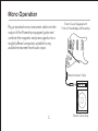
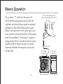
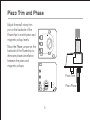
USER GUIDE
POWERCHIP
Welcome
Thank you for making Fishman a part of your acoustic experience. We are proud
to offer you the finest acoustic amplification products available: high-quality
professional-grade tools which empower you to sound your very best.
Troubleshooting
If you are unfamiliar with this product, please pay close attention to the requirements for installation. Failure to do so can result in permanent damage to the pickup.
Installation by a qualified professional is strongly recommended.
Technical support, troubleshooting tips and installation information can be
found at http://www.fishman.com/support/
Description and Features
The Powerchip is a miniature onboard piezo / magnetic pickup mixing preamp,
dedicated to the Fishman Powerbridge system. The preamp, mounted to the
underside of a piezo volume pot, allows guitarists to combine or split piezo and
magnetic pickups without any additional outboard signal routing electronics.
2
Mono Operation
Plug a standard mono instrument cable into the
output of the Powerchip equipped guitar and
combine the magnetic and piezo signals into a
single buffered composite, suitable for any
available instrument level audio input.
Electric Guitar Equipped with
Fishman Powerbridge and Powerchip
Mono Instrument Cable
3
Electric Guitar Amp
Stereo Operation
Plug a stereo “Y” cable into the output of
the Powerchip equipped guitar and split the
magnetic and piezo pickup signals to separate
destinations. Send the buffered piezo signal
(Ring) to any instrument level audio input, such
as an acoustic instrument amplifier or PA system.
Send the unbuffered, “immaculate” magnetic
pickup signal (Tip) to a traditional electric guitar
amplifier, with no added coloration or signal
treatment between the magnetic pickup and
the amplifier.
4
Electric Guitar Equipped with
Fishman Powerbridge and Powerchip
Stereo Y-Cable
Powerbridge
Signal (Ring)
Magnetic
Signal (Tip)
Acoustic Guitar Amp
Electric Guitar Amp
Piezo Trim and Phase
Adjust the small rotary trim
pot on the backside of the
Powerchip to match piezo and
magnetic pickup levels.
Move the Phase jumper on the
backside of the Powerchip to
eliminate phase cancellation
between the piezo and
magnetic pickups.
Piezo Trim
Piezo Phase
5
Prepare the Instrument
Telecaster style guitars
File or sand down the corners of the 9-pin jack
to fit the standard Telecaster mounting hole.
Stratocaster style guitars
You will need to drill out the back
wall of the jack cavity to accommodate the supplied 9-pin jack.
Remove the output jack from the
jack plate, then replace the jack
plate on the guitar. Use a pencil
through the jackplate to mark the
center where your drill will enter
the back of the jack cavity. Use a
¾” (19mm) spade bit to drill out
the back of the jack cavity.
Jack Plate
9 Pin Jack
6
Installation and Connections
Warning: The solder pad terminals and the adjacent components on the
Powerchip circuit board are quite fragile and can be easily overheated. Use only
a low wattage soldering iron (30 watts max) to make your wire connections. To
best utilize the space inside the guitar, solder the wires to the circuit board so
that they exit toward the volume pot terminals.
1. Strip 3⁄32” (2.4mm) and tin the wire ends of the pickups.
2. Solder the piezo pickup wire to the circuit board.
Red
Battery
The pads are located on the side of the board
Wire
opposite the volume pot. The piezo hot wire
goes to the pad on the right edge of the
board, directly under and to the right of the
Piezo Hot
little white trimmer pot. Solder the piezo
Piezo Ground
ground wire (which should be left with the
Common
Output Ground
braid intact) to the pad labeled “G” on the
Ground
(Sleeve)
right edge of the board, directly under the
piezo hot wire.
7
3. Solder the magnetic pickup hot wire to the circuit board.
The pad for the hot wire is located on the same side of the board as the volume
pot. This pad, labeled “M,” is on the left edge of the board, ¾” (19mm) from the
bottom of the board. A common system ground is located on the opposite side
of the board, on a second pad marked “G,” adjacent to the piezo ground. Since
there is room for only one wire on this pad, we suggest that you tie all grounds to
the body of the magnetic volume pot, and run a jumper wire to the ground pad
on the circuit board.
Note: If you install the Powerchip
with active magnetic pickups (such
as EMG), the Powerchip and the
active pickups will share the same
battery. Connect the positive battery
wire from the magnetics to the +9V
pad on the Powerchip. Connect
the negative battery wire from the
magnetics to terminal #1 on the
9-pin jack.
Output (Tip)
Magnetic In
Output (Ring)
3-Position
Switch (Optional)
8
4. Solder the 9-pin jack to the system.
A prewired output cable from the Powerchip is to be soldered to the provided
9-pin jack. Prepare the jack by soldering a jumper wire between the sleeve
terminal, located on the business end of the jack, and terminal #2, directly below.
Solder the jack as follows:
a. Solder the shield from the output cable to terminal #2.
b.Solder the red wire from the output cable to terminal #4.
c. Solder the white wire
from the output cable
the terminal #8.
Sleeve
d.Solder the black
battery wire (negative)
to terminal #1.
Output Ground
(Sleeve)
Black
Battery
Wire
Jumper
Wire
Terminal
#2
9
Red Output
Wire (Tip)
White Output
Wire (Ring)
Optional Accessories
• Battery Compartment—a flush mounted, pivoting compartment allows
easy access and quick battery changes.
• Piezo/Magnetic Pickup Selector Switch—a three position switch for
selecting between piezo and magnetic pickup combinations (see below).
Optional Piezo/Magnetic
Pickup Selector Switch
10
Specifications
Battery Life:
Current Draw:
Frequency Range:
Trim Control Range:
Maximum Output Voltage:
200 Hours
Less than 2.8mA
20–20,000 Hz
18dB
15V peak to peak
11
WWW.FISHMAN.COM
009-074-001 Rev E 5-10