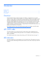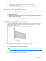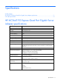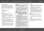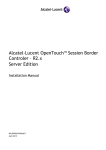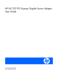
1
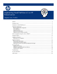
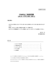
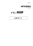
HP NC364T PCI Express Quad Port Gigabit Server Adapter User Guide Part Number 445893-00B June 2007 (First Edition) © Copyright 2007 Hewlett-Packard Development Company, L.P. The information contained herein is subject to change without notice. The only warranties for HP products and services are set forth in the express warranty statements accompanying such products and services. Nothing herein should be construed as constituting an additional warranty. HP shall not be liable for technical or editorial errors or omissions contained herein. Audience assumptions This document is for the person who installs, administers, and troubleshoots servers and storage systems. HP assumes you are qualified in the servicing of computer equipment and trained in recognizing hazards in products with hazardous energy levels. Contents Technician notes ........................................................................................................................... 4 Where to go for additional help.................................................................................................................. 5 HP contact information ..................................................................................................................... 5 Introduction .................................................................................................................................. 6 Overview ................................................................................................................................................. 6 UTP CAT5 cable ....................................................................................................................................... 6 LED indicators ........................................................................................................................................... 6 Installing an adapter ..................................................................................................................... 8 Installation overview .................................................................................................................................. 8 Preventing electrostatic discharge ................................................................................................................ 8 Installing a low profile bracket .................................................................................................................... 9 Installing an adapter in a server .................................................................................................................. 9 Connecting the network cable................................................................................................................... 10 Specifications ............................................................................................................................. 11 HP NC364T PCI Express Quad Port Gigabit Server Adapter specifications..................................................... 11 UTP cable specifications........................................................................................................................... 12 Regulatory compliance notices ..................................................................................................... 13 Regulatory compliance identification numbers ............................................................................................. 13 Federal Communications Commission notice............................................................................................... 13 Class B equipment................................................................................................................................... 13 Declaration of conformity for products marked with the FCC logo, United States only....................................... 14 Modifications.......................................................................................................................................... 14 Canadian notice ..................................................................................................................................... 14 European Union regulatory notice ............................................................................................................. 15 Japanese class B notice............................................................................................................................ 15 Korean class B notice............................................................................................................................... 15 BSMI notice ............................................................................................................................................ 16 Disposal of waste equipment by users in private households in the European Union ......................................... 16 Electrostatic discharge ................................................................................................................. 17 Preventing electrostatic discharge .............................................................................................................. 17 Grounding methods to prevent electrostatic discharge .................................................................................. 17 Acronyms and abbreviations........................................................................................................ 18 Index......................................................................................................................................... 20 Contents 3 Technician notes In this section Where to go for additional help ................................................................................................................ 5 WARNING: Only authorized technicians trained by HP should attempt to repair this equipment. All troubleshooting and repair procedures are detailed to allow only subassembly/module-level repair. Because of the complexity of the individual boards and subassemblies, no one should attempt to make repairs at the component level or to make modifications to any printed wiring board. Improper repairs can create a safety hazard. WARNING: To reduce the risk of electric shock, personal injury, and damage to the equipment: • Do not attempt to service any parts of the equipment other than those specified in the following procedure. Any other activities may require that you shut down the server and remove the power cord. • Installation and maintenance of this product must be performed by individuals who are knowledgeable about the procedures, precautions and hazards associated with the product. WARNING: To reduce the risk of electric shock or damage to the equipment: • Do not disable the power cord grounding plug. The grounding plug is an important safety feature. • Plug the power cord into a grounded (earthed) electrical outlet that is easily accessible at all times. • Unplug the power cord from the power supply to disconnect power to the equipment. • Do not route the power cord where it can be walked on or pinched by items placed against it. Pay particular attention to the plug, electrical outlet, and the point where the cord extends from the server. CAUTION: To properly ventilate the system, you must provide at least 7.6 cm (3.0 in) of clearance at the front and back of the server. CAUTION: The server is designed to be electrically grounded (earthed). To ensure proper operation, plug the AC power cord into a properly grounded AC outlet only. NOTE: Any indications of component replacement or printed wiring board modifications may void any warranty. Technician notes 4 Where to go for additional help 1. Go to the HP website (http://www.hp.com). 2. Click Software & Driver Downloads from the left menu bar. 3. Type the product name in the For product box and press Enter. For example, type NC370T. 4. Download the drivers, firmware, or documentation as needed. HP contact information For the name of the nearest HP authorized reseller: • In the United States, see the HP US service locator webpage (http://www.hp.com/service_locator). • In other locations, see the Contact HP worldwide (in English) webpage (http://welcome.hp.com/country/us/en/wwcontact.html). For HP technical support: • • In the United States, for contact options see the Contact HP United States webpage (http://welcome.hp.com/country/us/en/contact_us.html). To contact HP by phone: o Call 1-800-HP-INVENT (1-800-474-6836). This service is available 24 hours a day, 7 days a week. For continuous quality improvement, calls may be recorded or monitored. o If you have purchased a Care Pack (service upgrade), call 1-800-633-3600. For more information about Care Packs, refer to the HP website (http://www.hp.com). In other locations, see the Contact HP worldwide (in English) webpage (http://welcome.hp.com/country/us/en/wwcontact.html). Technician notes 5 Introduction In this section Overview ................................................................................................................................................ 6 UTP CAT5 cable ...................................................................................................................................... 6 LED indicators .......................................................................................................................................... 6 Overview The HP NC364T PCI Express Quad Port Gigabit Server Adapter is a high-performance, low-profile, Quad-Port PCI Express Ethernet adapter that delivers up to 1000 Mb/s Ethernet over twisted-pair (copper) category 5 or better cabling. It is powered by an Intel 82571EB chipset. The NC364T adapter, which ships with a standard-height chassis bracket and also includes a low-profile chassis bracket, has a fully integrated controller capable of auto-negotiating a link at 10, 100, or 1000 Mb/s. Network connection is made through the four RJ-45 connectors. LED indicators show the link speed and activity. See LED indicators (on page 6) for details. The adapter is a supported option for selected HP ProLiant servers. The adapter must be installed in a PCI Express slot. For the latest functionality, features, and operating system support for this adapter, see the HP website (http://h18004.www1.hp.com/products/servers/networking/index-nic.html). UTP CAT5 cable The NC364T adapter can use existing UTP CAT5 (or better) cable to deliver Gigabit Ethernet over copper, according to the IEEE 802.3ab specifications. For new installations, CAT5e (enhanced CAT5) cable is recommended. For troubleshooting and other information about cabling, see UTP Cable Specifications (on page 12). LED indicators The NC364T adapter has four auto-negotiating 10/100/1000 RJ-45 ports. LED indicators show activity, link and port speed. Standard-height and low-profile brackets are shown below with RJ-45 ports and LED indicators. Introduction 6 The NC360T Gigabit Server Adapter LED indicators operate as described in the following table. LED indicator Status Description ACT/LINK On This mono-color green LED indicates that the link to the adapter is established. The adapter is receiving power and the cable connection is working. Off No link to the adapter is established. The adapter is not receiving power or the cable connection is faulty. Flashing The adapter is sending or receiving network data at 10/100/1000 Mb/s, as indicated by the 10/100/1000 (speed) LED. The adapter is receiving power, and the cable connection is working. Off The adapter is connected at 10 Mb/s. Green The adapter is connected at 100 Mb/s. Orange The adapter is connected at 1000 Mb/s. Speed Introduction 7 Installing an adapter In this section Installation overview ................................................................................................................................. 8 Preventing electrostatic discharge............................................................................................................... 8 Installing a low profile bracket ................................................................................................................... 9 Installing an adapter in a server................................................................................................................. 9 Connecting the network cable.................................................................................................................. 10 Installation overview This section describes installation precautions, how to install the adapter, and how to connect the network cable. WARNING: To reduce the risk of personal injury or damage to the equipment, consult the safety information and user documentation provided with the server before attempting the installation. Many servers are capable of providing energy levels that are considered hazardous and are intended to be serviced only by qualified personnel who have been trained to deal with these hazards. Do not remove enclosures or attempt to bypass any interlocks that may be provided for the purpose of removing these hazardous conditions. WARNING: Installation of this adapter should be performed by individuals who are both qualified in the servicing of computer equipment, and trained in the hazards associated with products capable of producing hazardous energy levels. This adapter is intended to be installed in Certified (UL or CSA) ITE equipment having instructions for adding and removing user installed components such as PCI, PCI-X, and PCI Express devices. Refer to the equipment instructions to verify that it is suitable for user installed components and that it has the power capacity to support all of the installed components. NOTE: Before removing the cover of your server, refer to the HP documentation for the proper methods for installing a PCI Express card and avoiding electric shock hazards. Preventing electrostatic discharge To prevent damaging the system, be aware of the precautions you need to follow when setting up the system or handling parts. A discharge of static electricity from a finger or other conductor may damage system boards or other static-sensitive devices. This type of damage may reduce the life expectancy of the device. To prevent electrostatic damage: • Avoid hand contact by transporting and storing products in static-safe containers. • Keep electrostatic-sensitive parts in their containers until they arrive at static-free workstations. Installing an adapter 8 • Place parts on a grounded surface before removing them from their containers. • Avoid touching pins, leads, or circuitry. • Always be properly grounded when touching a static-sensitive component or assembly. Installing a low profile bracket You may have to install a low profile bracket to complete the product installation. The low profile bracket replaces the existing standard profile bracket shipped on the product. To install a low profile bracket: 1. Using a correctly sized slotted screwdriver, carefully remove the two board lock screws located at the top and bottom of the connector. 2. Remove the standard profile bracket and place the low profile bracket over the connector. Be careful not to damage the connector or bind the low profile bracket to the connector. Installing an adapter in a server The NC364T can be installed in a standard or low-profile PCI Express slot. The kit includes brackets for both slot types. See the HP ProLiant server documentation for additional information on how to safely install a PCI Express card in the server. 1. Power down the server, unplug the power cord from the power outlet, and then remove the server access panel. 2. Remove the expansion slot cover from a PCI Express slot. WARNING: To reduce the risk of personal injury from hot surfaces, allow the drives and the internal system components to cool before touching them. 3. Firmly seat the adapter in a PCI Express slot and secure the adapter bracket. 4. Replace the access panel and plug in the power cord. Installing an adapter 9 Connecting the network cable To secure the cable, plug the cable connector into the RJ-45 port. Ensure that the tab on the plug clicks into position indicating that it is properly seated. For more information, see UTP cable specifications (on page 12). Installing an adapter 10 Specifications In this section HP NC364T PCI Express Quad Port Gigabit Server Adapter specifications ................................................... 11 UTP cable specifications.......................................................................................................................... 12 HP NC364T PCI Express Quad Port Gigabit Server Adapter specifications Specification Value Network Controller Chipsets Two intel® 82571GB Dual MAC/PHY Bus Type x4 PCI Express v1.0a Bus Width Four lane On-board Memory 96 KB Data Transfer Method Bus Master DMA Boot ROM Support Yes Management Capabilities WOL, PXE 2.2, ACPI 1.1a Power Requirement 1250 mA @ 12V maximum Data Transmission Rate 10 Full/10 Half, 100 Full/100 Half, 1000 Full Standards Supported IEEE 802.3, IEEE 802.3u, IEEE 802.3ab, IEEE 802.3x (flow control), IEEE 802.3ad (link aggregation), IEEE 802.1p (QoS), IEEE 802.1q (VLAN tagging), IEEE802.3z Dimensions 12.95 cm x 6.86 cm [5.1 in x 2.7 in (L x W)] (without bracket) Connector and Distances 10BASE-T: Category 3, 4, or 5 UTP 100 M (328 ft) 100BASE-TX: CAT5 UTP 100 M (328 ft) 1000BASE-TX: CAT5 UTP 100 M (328 ft) Interrupts Supported Automatically configured Temperature Range Operating: 0°C to 55°C (32°F to 131°F) Storage: -65°C to 85°C (-85°F to 185°F) Relative Humidity (noncondensing) Operating: 10% to 90% Safety Compliance UL Mark (US and Canada) Storage: 5% to 95% CE Mark EN 60590 RoHS (European Union) Specifications 11 UTP cable specifications The NC364T adapter can use existing UTP CAT5 (or better) cable to deliver Gigabit Ethernet over copper, according to the IEEE 802.3ab specifications. For new installations, CAT5e (enhanced CAT5) cable is recommended. Maximum distances for Gigabit over copper cable are 100 meters (328 feet). To connect to the network, the NC364T uses the following cable for 1000Base-T transmission: • CAT5 UTP or better twisted-pair • 22-26 AWG, 100Ω @ 1 MHz • EIA/TIA 568a or EIA/TIA 568b Specifications 12 Regulatory compliance notices In this section Regulatory compliance identification numbers ........................................................................................... 13 Federal Communications Commission notice ............................................................................................. 13 Class B equipment.................................................................................................................................. 13 Declaration of conformity for products marked with the FCC logo, United States only..................................... 14 Modifications......................................................................................................................................... 14 Canadian notice .................................................................................................................................... 14 European Union regulatory notice ............................................................................................................ 15 Japanese class B notice........................................................................................................................... 15 Korean class B notice.............................................................................................................................. 15 BSMI notice ........................................................................................................................................... 16 Disposal of waste equipment by users in private households in the European Union....................................... 16 Regulatory compliance identification numbers For the purpose of regulatory compliance certifications and identification, this product has been assigned a unique regulatory model number. The regulatory model number can be found on the product nameplate label, along with all required approval markings and information. When requesting compliance information for this product, always refer to this regulatory model number. The regulatory model number is not the marketing name or model number of the product. Federal Communications Commission notice Part 15 of the Federal Communications Commission (FCC) Rules and Regulations has established Radio Frequency (RF) emission limits to provide an interference-free radio frequency spectrum. Many electronic devices, including computers, generate RF energy incidental to their intended function and are, therefore, covered by these rules. These rules place computers and related peripheral devices into two classes, A and B, depending upon their intended installation. Class A devices are those that may reasonably be expected to be installed in a business or commercial environment. Class B devices are those that may reasonably be expected to be installed in a residential environment (for example, personal computers). The FCC requires devices in both classes to bear a label indicating the interference potential of the device as well as additional operating instructions for the user. Class B equipment This equipment has been tested and found to comply with the limits for a Class B digital device, pursuant to Part 15 of the FCC Rules. These limits are designed to provide reasonable protection against harmful interference in a residential installation. This equipment generates, uses, and can radiate radio frequency energy and, if not installed and used in accordance with the instructions, may cause harmful interference to radio communications. However, there is no guarantee that interference will not occur in a particular installation. If this equipment does cause harmful interference to radio or television reception, which can Regulatory compliance notices 13 be determined by turning the equipment off and on, the user is encouraged to try to correct the interference by one or more of the following measures: • Reorient or relocate the receiving antenna. • Increase the separation between the equipment and receiver. • Connect the equipment into an outlet on a circuit that is different from that to which the receiver is connected. • Consult the dealer or an experienced radio or television technician for help. Declaration of conformity for products marked with the FCC logo, United States only This device complies with Part 15 of the FCC Rules. Operation is subject to the following two conditions: (1) this device may not cause harmful interference, and (2) this device must accept any interference received, including interference that may cause undesired operation. For questions regarding this product, contact us by mail or telephone: • Hewlett-Packard Company P. O. Box 692000, Mail Stop 530113 Houston, Texas 77269-2000 • 1-800-HP-INVENT (1-800-474-6836). (For continuous quality improvement, calls may be recorded or monitored.) For questions regarding this FCC declaration, contact us by mail or telephone: • Hewlett-Packard Company P. O. Box 692000, Mail Stop 510101 Houston, Texas 77269-2000 • 1281-514-3333 To identify this product, refer to the part, series, or model number found on the product. Modifications The FCC requires the user to be notified that any changes or modifications made to this device that are not expressly approved by Hewlett-Packard Company may void the user’s authority to operate the equipment. Canadian notice This Class B digital apparatus meets all requirements of the Canadian Interference-Causing Equipment Regulations. Cet appareil numérique de la classe B respecte toutes les exigences du Règlement sur le matériel brouilleur du Canada. Regulatory compliance notices 14 European Union regulatory notice This product complies with the following EU Directives: • Low Voltage Directive 2006/95/EC • EMC Directive 2004/108/EC Compliance with these directives implies conformity to applicable harmonized European standards (European Norms) which are listed on the EU Declaration of Conformity issued by Hewlett-Packard for this product or product family. This compliance is indicated by the following conformity marking placed on the product: This marking is valid for non-Telecom products and EU harmonized Telecom products (e.g. Bluetooth). This marking is valid for EU non-harmonized Telecom products. *Notified body number (used only if applicable—refer to the product label) Hewlett-Packard GmbH, HQ-TRE, Herrenberger Strasse 140, 71034 Boeblingen, Germany Japanese class B notice Korean class B notice Regulatory compliance notices 15 BSMI notice Disposal of waste equipment by users in private households in the European Union This symbol on the product or on its packaging indicates that this product must not be disposed of with your other household waste. Instead, it is your responsibility to dispose of your waste equipment by handing it over to a designated collection point for the recycling of waste electrical and electronic equipment. The separate collection and recycling of your waste equipment at the time of disposal will help to conserve natural resources and ensure that it is recycled in a manner that protects human health and the environment. For more information about where you can drop off your waste equipment for recycling, please contact your local city office, your household waste disposal service or the shop where you purchased the product. Regulatory compliance notices 16 Electrostatic discharge In this section Preventing electrostatic discharge............................................................................................................. 17 Grounding methods to prevent electrostatic discharge ................................................................................ 17 Preventing electrostatic discharge To prevent damaging the system, be aware of the precautions you need to follow when setting up the system or handling parts. A discharge of static electricity from a finger or other conductor may damage system boards or other static-sensitive devices. This type of damage may reduce the life expectancy of the device. To prevent electrostatic damage: • Avoid hand contact by transporting and storing products in static-safe containers. • Keep electrostatic-sensitive parts in their containers until they arrive at static-free workstations. • Place parts on a grounded surface before removing them from their containers. • Avoid touching pins, leads, or circuitry. • Always be properly grounded when touching a static-sensitive component or assembly. Grounding methods to prevent electrostatic discharge Several methods are used for grounding. Use one or more of the following methods when handling or installing electrostatic-sensitive parts: • Use a wrist strap connected by a ground cord to a grounded workstation or computer chassis. Wrist straps are flexible straps with a minimum of 1 megohm ±10 percent resistance in the ground cords. To provide proper ground, wear the strap snug against the skin. • Use heel straps, toe straps, or boot straps at standing workstations. Wear the straps on both feet when standing on conductive floors or dissipating floor mats. • Use conductive field service tools. • Use a portable field service kit with a folding static-dissipating work mat. If you do not have any of the suggested equipment for proper grounding, have an authorized reseller install the part. For more information on static electricity or assistance with product installation, contact an authorized reseller. Electrostatic discharge 17 Acronyms and abbreviations ACPI Advanced Configuration and Power Interface APM advanced power management CSA Canadian Standards Association DMA direct memory access IEEE Institute of Electrical and Electronics Engineers LED light-emitting diode MDI medium dependent interface MDI-X medium dependent interface-crossover NIC network interface controller PCI Express Peripheral Component Interconnect Express PXE Preboot Execution Environment RoHS Restriction of Hazardous Substances Acronyms and abbreviations 18 UTP unshielded twisted pair VDC voltage direct-current WOL Wake-on LAN Acronyms and abbreviations 19 Index C cable configuration 11 cable connectors 11 cables, networking 9 E electrostatic discharge 7, 16 F features 5 G grounding methods 16 I installation overview 7 installing adapters 8 N NIC LEDs 5 R regulatory compliance notices 12 S specifications 10 U UTP CAT5 cable 11 Index 20