1
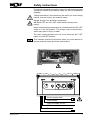
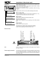
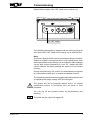
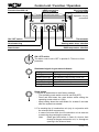
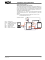
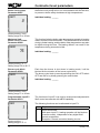
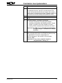
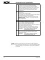
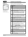
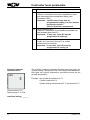
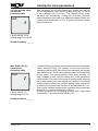
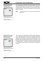
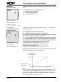
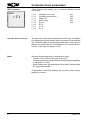
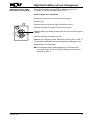
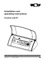
Installation and
operating instructions
Control unit R1
Wolf GmbH · Postfach 1380 · D-84048 Mainburg · Tel. +49-8751/74-0 · Fax +49-8751/741600 · Internet: www.wolf-heiztechnik.de
3061809_1210
Subject to modifications
GB
Index
Safety instructions.......................................................................3
Standards / Regulations..............................................................4
Installation / Electrical work..................................................... 5-6
Commissioning............................................................................7
Control unit / Function / Operation ....................................... 8-10
Displaying / Modifying control parameters................................11
Contractor level parameters................................................ 12-28
Setting the eBUS address.........................................................29
Parameter setup report.............................................................30
High limit safety cut-out changeover.........................................31
Sensor resistances....................................................................32
Wiring diagram boiler control unit R1........................................33
Specification..............................................................................34
Fault messages.........................................................................35
2
3061809_1210
Safety instructions
The following symbols are used in conjunction with these important
instructions concerning personal safety as well as operational
reliability.
"Safety instructions" are instructions with which you must comply
exactly, to prevent injury and material losses.
Danger through 'live' electrical components.
NB Switch OFF the ON / OFF switch before removing the
casing.
Never touch electrical components or contacts when the ON / OFF
switch is in the ON position. This brings a risk of electrocution,
which may result in injury or death.
The main supply terminals are 'live' even when the ON / OFF
switch is in the OFF position.
NB
This indicates technical instructions which you must observe to
prevent material losses and boiler malfunctions.
Burner supply cable
Boiler sensor
High limit safety cut-out
Earth terminal
Thermometer
3061809_1210
3
Standards / Regulations
Installation / Commissioning The boiler control unit complies with the following regulations:
ECDirectives
- 2006/95/EC
- 2004/108/EC
LowVoltageDirective
EMCGuideline
DIN/ENStandards
EN60335-1,EN60730-2-9,EN14597,
DIN3440,EN50165,EN55014-1
Regarding the installation, observe the following regulations, rules
and directives.
- Theinstallationandcommissioningoftheheatingsystem
- LocalEMCregulations
- DIN VDE 0100 Regulations regarding the installation of high voltage
systemsupto1000V
- DINVDE105Operationofelectricalsystems
- EN50156Electricalequipmentincombustionsystems
- EN12828Heatingsystemsinbuildings
Appropriate use
TheWolfR1controlunitisdesignedexclusivelyforuseinconjunctionwith
Wolfboilers.TheR1controlunitisequippedwithatemperaturecontroller/
limiterandahighlimitsafetycut-out.Thecontrolunitregulatessinglestage
burners.Thesetboilertemperaturecanbeselectedbetween38-90°C.
The R1 control unit can be extended with a BM programming unit for
weather-compensatedtemperaturecontrolwithtimeprogram.
Other applicable documents
Boilerinstallationandoperatinginstructions.
Instructionsforallaccessoriesused.
Warnings
- Neverremove,bypassordisablesafetyandmonitoringequipment.
- Only operate the system in perfect technical condition. Immediately
remove/remedyanyfaultsanddamagewhichmayimpactonsafety.
- Alwaysensurethatcoldwaterismixedinwithhotwater,whentheDHW
temperature is set above 60 °C or when operating the pasteurisation
system(65°C)(riskofscalding).
Maintenance / Repair
-Regularlychecktheperfectfunctionofallelectricalequipment.
-Onlyqualifiedpersonnelmayremovefaultsorrepairdamage.
-OnlyreplacefaultycomponentsorequipmentwithoriginalWolfspare
parts.
- Alwaysmaintainprescribedelectricalprotectionvalues(seespecification).
NB
4
AnydamageorlossresultingfromtechnicalmodificationstoWolfcontrol
unitsisexcludedfromourliability.
3061809_1210
Installation / Electrical work
Installation
When installing this control unit ensure that sensor capillaries are
neither kinked nor twisted.
Never route on-site sensor and remote control leads / cables
together with mains power cables.
Implement the electrical wiring in accordance with the wiring
diagram.
Open the rear control unit cover after releasing both screws.
Burner supply cable
Boiler sensor
High limit safety
cut-out
Burner supply cable
Guide it through the aperture in the control unit bracket (l.h. / r.h.),
subject to the side to which the boiler door opens.
Boiler sensor
Insert into any opening of the boiler sensor well.
Earth terminal
High limit safety cut-out
Insert sensor capillaries into any opening in the boiler sensor
well.
Thermometer
Earth terminal
Insert into the control unit panel.
Thermometer for boiler water temperature display
Insert into any opening of the boiler sensor well.
LP = Primary pump
Mains 230 V
KKP = Boiler circuit pump
A1 = Programmable output
AF = Outside temp. sensor
SF = Cylinder sensor
E1 = Programmable input
eBUS
Electrical work
Info
Insert all plugs that are not used into the plug-in strip. Observe
the colour coding.
Power supply connection
Join the power supply cable to the plug supplied. Insert the plug
into the marked-up location in the plug-in connector strip, and
secure the cable with its strain relief. Route the cable through the
boiler back cutout.
3061809_1210
5
Installation / Electrical work
Pump connection
Wolf boiler circuit and DHW cylinder primary pumps are factoryfitted with plugs. Route the cable through the boiler back cutout.
Insert the plug into the marked-up locations in the plug-in connector
strip, and secure the cables with their strain relief.
A1
programmable output
Join the cable of output A1 to the plug supplied. Insert the plug
into the marked-up location in the plug-in connector strip, and
secure the cable with its strain relief. Route the cable through the
boiler back cutout.
Outside temperature
sensor
(accessory)
Join the on-site lead of the outside temperature sensor with the
plug supplied. Insert the plug into the marked-up location in the
plug-in connector strip, and secure the lead with its strain relief.
Route the lead through the boiler back cutout. Fit the outside
temperature sensor to the north or northeast wall, 2 to 2.5m
above ground level.
DHW sensor
(accessory)
Push the DHW cylinder sensor (accessory) into the cylinder sensor
well. Route the lead through the boiler back cutout. Insert the plug
into the marked-up location in the plug-in connector strip, and
secure the lead with its strain relief.
E1
programmable input
Join the cable of input E1 with the plug supplied. Insert the plug
into the marked-up location in the plug-in connector strip, and
secure the cable with its strain relief. Route the cable through the
boiler back cutout.
eBUS accessories
Remote control, radio clock module, radio clock module with outside
temperature sensor, receiver for wireless outside temperature
sensor and wireless analog remote control.
Join the on-site accessory cable with the green plug supplied
(designated eBUS). Insert the plug into the marked-up location
in the plug-in connector strip, and secure the cable with its strain
relief. Route the cable through the boiler back cutout.
Note:
If several eBUS accessories are to be connected simultaneously,
connect these in parallel at the eBUS terminal.
6
3061809_1210
Commissioning
Switch ON the system ON / OFF switch at the control unit.
ON / OFF switch
The heating system starts to operate with the factory settings as
soon as the ON / OFF switch at the control unit is switched ON.
Note:
The factory settings of the control unit represent empirical values.
Subject to system or equipment level, control parameters other
than those chosen at the factory can be selected. Make changes
via the Wolf control accessories or via a PC / laptop with Wolf
control software. All factory settings are stored in a non-volatile
memory.
During commissioning, the control unit automatically recognises
any connected cylinder and / or outside temperature sensor.
The outside temperature sensor is logged off by disconnection and
by switching the supply voltage OFF and ON again.
The system will not be protected against frost if no outside
temperature sensor is connected; only the boiler is frost
protected.
You can log off the cylinder sensor by disconnecting and
resetting.
NB
3061809_1210
The boiler sensor cannot be logged off.
7
Control unit / Function / Operation
Fine-wire fuse M 6.3 A
eBUS connection
for PC / Laptop
High limit safety
cut-out (STB)
Operation only by
contractors
ON / OFF switch
Thermometer
Illuminated ring
Heating water temp. selection
Reset button
DHW temperature selection
ON / OFF switch
The boiler control unit is OFF in position 0. There is no frost
protection.
Illuminated signal ring as status indicator
Display
Flashing green
Constant green light
Flashing yellow
Constant yellow light
Flashing red
Explanation
Standby (power supply ON, no heat demand)
Heat demand: pump running, burner OFF
Emissions test mode
Burner ON, flame steady
Fault
Reset button
1. Resets all parameters to their factory settings.
- The operating mode switch must be set to O (OFF).
- Press and hold down the reset button whilst setting the
operating mode switch to I (ON).
- Keep holding down the reset button for at least 2 seconds
after the system has started.
2. For resetting the oil combustion unit (only in conjunction with
the relevant Wolf components)
- In case of a burner fault, the oil combustion unit is reset via
a reset relay by pressing the reset key.
Note:
Reset gas fired boilers in case of a burner fault
directly at the gas combustion unit, i.e. through an
opening in the silencer hood.
8
3061809_1210
Control unit / Function / Operation
DHW temperature selection (rotary selector)
When boilers are combined with a DHW cylinder, setting 1-9
corresponds to a cylinder temperature of 15-60 °C. The adjustment
made at the DHW temperature selector is ineffective when the
system is used in conjunction with a digital room temperature
controller or a weather-compensated controller. The temperature
will then be selected at the controller (accessory).
Heating water temperature selection (rotary selector)
The setting range 2 - 8 corresponds to a heating water temperature
of 38 to 75 °C (factory setting).
The adjustment at the heating water temperature controller is
ineffective when the system is used in conjunction with a digital
room temperature controller or a weather-compensated controller
(exception: emissions test mode).
The heating water temperature is calculated from the controller
setting.
Winter mode (position 2 to 8)
In winter mode, the boiler heats to the temperature selected at
the heating water temperature controller. According to the pump
operating mode, the circulation pump operates constantly (factory
setting) or only in parallel with the burner activation / run-on
period.
Summer mode
The winter mode is disabled and summer mode is enabled by rotating
the heating water temperature selector into position
. Summer
mode (heating OFF) means only DHW heating. Frost protection
for the heating system and pump anti-seizing protection, however,
remain enabled.
Emissions test mode
The emissions test mode is enabled by rotating the heating water
. Any previous burner cycle block will
temperature selector to
be cancelled. The signal ring flashes yellow. The heating system
will not operate in weather-compensated mode, when the emission
test has been enabled. Instead it operates at maximum output and
tries to hold a mean constant boiler water temperature of 60 °C.
Only the burner will operate, i.e. the pump is OFF, if the boiler
water temperature is lower than 60 °C. The boiler circuit pump
will be started when the boiler water temperature exceeds 60 °C.
The DHW cylinder primary pump only runs until the set DHW
temperature has been reached. The burner is switched OFF when
the max. boiler water temperature has been reached, if the heating
energy supplied cannot be transferred.
The emissions test mode terminates either after 15 minutes or
automatically, if the maximum flow temperature has been exceeded.
For a repeat activation, turn the heating water temperature selector
first anti-clockwise and then back into position
.
3061809_1210
9
Control unit / Function / Operation
Thermometer
to display the current heating water temperature.
Fine-wire fuse
M 6.3 A to protect the control PCB.
eBUS connection
for data transfer between the control unit and the PC / laptop
with the software set for boiler control units (accessory).
High limit safety cut-out STB
factory-set to 110 °C; adjustable to 100 °C, if required.
Anti-seizing pump
protection
10
In summer mode, the circulation pump operates for approx. 10
seconds after a maximum idle period of 24 hours. Then, the
cylinder primary pump and the DHW circulation pump (if installed)
will run for 20 seconds. This prevents the pump from seizing up.
The burner will be switched OFF for approx. two minutes if it is
operating when the anti-seizing pump protection is enabled.
3061809_1210
Displaying / Modifying control parameters
The control parameters can only be modified or displayed via Wolf control accessories
with eBUS capability. For procedures, check the operating instructions of the relevant
accessories.
NB
Modificationsmustonlythecarriedoutbyarecognisedheatingcontractor
orbytheWolfcustomerservice.
NB
Incorrectoperationcanleadtosystemfaults.
Please note when adjusting parameterA09 (frost protection / outside
temperature), that frost protection is no longer safeguarded if you set
temperatureslowerthan0°C.Thiscanresultindamagetotheheating
systemandallitscomponents(e.g.pipes,radiators,etc.).
Parameter overview
(Settingsandfunctionsonthefollowingpages)
Parameter
Setting range
-20to+10°C
Factory setting
A09
Frostprotectionlevel
A10
A14
HG01
ParallelDHWoperation
HG06
Pumpoperatingmode
HG07
Boilercircuitpumprun-ontime
0to30min
3min
HG08
MaximumlimitboilercircuitTV-max
40to90°C
75°C
HG09
Burnercycleblock
1to30min
4min
HG13
ProgrammableinputE1
1 to 11
1
HG14
ProgrammableoutputA1
0 to 14
0
HG15
Cylinderhysteresis
HG19
Cylinderprimarypumprun-ontime
HG20
Max.cylinderheatingtime
0to5h
2h
HG21
MinimumboilerwatertemperatureTK-min.*
38to90°C
38°C
HG22
MaximumboilerwatertemperatureTK-max.
50to90°C
80°C
HG24
DHWsensoroperatingmode
HG25
BoilerexcesstemperatureduringDHWcylinder
heating
HG26
Boilersoftstart
0/1
1
HG32
Returntemperatureraising**
0to70°C
30°C
HG33
Hysteresistime
1to30min
10min
HG34
HG35
HG50
eBUSfeed
HG70
Display
Multifunction
-50sensorshortcircuitorcontactclosed
inputE1
ActualtemperatureheadersensorHG13=7
MaximumDHWtemperature
Burnerswitchingdifferential(dynamic)
0-5Vinputfortelecontrolsystem
Testfunctions
+2°C
0/1
0
60to80°C
5 to 30 K
65°C
15 K
0/1/2
0
1 to 30 K
5K
0to10min
3min
1/2/3
1
0 to 40 K
10 K
0/1/2
2
0/1
1 to 5
0
-
-60sensorleadbreakorcontactopen
ActualtemperaturereturnsensorHG13=11
* setto50°Cforpressurejetgasburners
** setto40°Cforpressurejetgasburners
3061809_1210
11
Contractor level parameters
Frost protection limit
Parameter A09
A09
The boiler circuit pump operates constantly if the outside
temperaturestaysbelowtheselectedvalue.Theburnerstartsand
heatstheboilertoamin.of38°C,iftheboilerwatertemperature
fallsbelow+5°C.
2.0
Note:
Onlychangethefactorysettingifyoucanensurethattheheating
system and its components will not freeze up at low outside
temperatures.
Factorysetting:2°C
Settingrange:-20to+10°C
Individual setting: ______
Parallel DHW operation
Parameter A10
A10
0
Factorysetting:0
Settingrange:0/1
Individual setting: ______
NB
Maximum DHW
temperature
Parameter A14
A14
The boiler circuit pump is switched OFF during DHW cylinder
heating with DHW priority (0). The boiler energy will then be
used exclusively for heating the DHW cylinder. The cylinder
primary pump will only start, if the boiler water temperature is
5 °C higher than the actual cylinder temperature. The burner
shutsdownandtheheatingcircuitpumpisstarted,assoonas
thecylinderhasreacheditssettemperature.Thecylinderprimary
pumprunsonforthemaximumperiodselectedunderparameter
HG19(cylinderprimarypumprun-ontime).
Theheatingcircuitpumpcontinuestooperateinparallel DHW
mode (1).Thecylinderprimarypumpstarts,iftheboilerwater
temperatureis5°Cwarmerthanthecylindertemperature.The
cylinder is fully heated up when the cylinder has reached the
selectedwatertemperature.Thecylinderprimarypumprunson
forthemaximumperiodselectedunderparameterHG19(cylinder
primarypumprun-ontime).
IntheparallelDHWmode(1),theheatingcircuitcantemporarily
beoperatedatahighertemperature.
This temperature can be enabled at 80 °C, if for commercial
reasonsahigherDHWtemperatureisrequired.
Ifpasteurisationhasbeenactivated(BM),theDHWcylinderwill
beheatedtotheselectedmaximumDHWtemperatureduringthe
firstcylinderheatingoftheday.
65.0°C
Factorysetting:65°C
Settingrange:60to80°C
Individual settings: _________
NB
12
Takeadequatemeasurestopreventscalding.ParameterHG22
(maximumboilerwatertemperature)shouldbesetatleast5K
higherthantheselectedmaximumDHWtemperature.
3061809_1210
Contractor level parameters
Burner switching differential The burner switching differential regulates the burner temperature
(dynamic)
within a set range by switching the burner ON and OFF. The higher
Parameter HG01
the ON / OFF temperature differential, the higher the boiler water
temperature fluctuation around the set value, resulting in longer
burner runtimes and vice versa. Longer burner runtimes protect
HG01
the environment and extend the service life of wearing parts
Factory setting: 15 K
Setting range: 5 to 30 K
Individual setting:_______
Switching differential (K)
15
Selected switching differential 15 K
Hysteresis time 10 minutes
Burner runtime (min.)
Fig.:
Time sequence of the dynamic burner switching differential for a
user-defined burner switching differential of 15 K and a selected
hysteresis time (parameter HG33) of 10 minutes.
3061809_1210
13
Contractor level parameters
Pump operating mode
Parameter HG06
HG06
0
Pump operating mode 0:
Heating circuit pump for heating systems without cascade
control and without low loss header
The heating circuit pump runs constantly when there is a heat
demand.TheheatingcircuitpumpwillbeswitchedOFFduring
DHWheating,ifDHWpriorityhasbeenselected.
Factorysetting:0
Settingrange:0/1
Individual setting: ______
Pump operating mode 1:
Feed pump for heating systems with cascade control and /
or low loss header
Heatingcircuitpumpbecomesthefeedpump.
Theheadersensoraffectstheheatingoperationaswellascylinder
heating.Thefeedpumprunsonlywhenthereisaburnerdemand.
Pumprun-oninaccordancewithparameterHG07.
Softstarting:AtTKIst < TKmin(38°C)feedpump"OFF".
MKP and cylinder primary pump continue to run with soft
starting.
Note: Increase the pump run-on time from 3 min to 15 min.
SettheparameterHG13to7.
Hydraulicscheme:
MK1
MKP
ZUP = Feedpump
SPL = Cylinderprimarypump
PLP = Bufferprimarypump
SF = Cylindersensor
SAF = Headersensor
MK1 = Mixercircuit
MKP= Mixercircuitpump
14
SAF
Oil/gasboiler
ZUP
Lowloss
header
orbuffer
cylinder
SF
Cylinder
SPL
3061809_1210
Contractor level parameters
Pump operating mode 2:
Buffer primary pump for BSP cylinder
Theheadersensor(buffer)onlyaffectstheheatingoperation.In
caseofcylinderheating,thereferencetemperatureisprovided
bytheinternalboilersensor.Inheatingmode,thebufferprimary
pumprunsonlywhenthereisaburnerdemand.Pumprun-onin
accordancewithparameterHG07.
Soft starting:At TKIst < TKmin (38 °C) buffer primary pump and
cylinder primary pump "OFF". MKP continues to run with soft
starting.
Note: Increasethepumprun-ontimefrom3minto15min.
SettheparameterHG13to7.
Hydraulicscheme:
MK1
MKP
ZUP = Feedpump
SPLP= Cylinderprimarypump
PLP = Bufferprimarypump
SF = Cylindersensor
SAF = Headersensor
MK1 = Mixercircuit
MKP = Mixercircuitpump
Wood
boiler
Buffercylinder
SF SPLP
PLP
Oil/gasboiler
SAF
Solarthermalsystem
integration
3061809_1210
15
Contractor level parameters
Run-on time
Boiler circuit pump
Parameter HG07
HG07
3
Subjecttotherebeingnoheatdemandfromtheheatingcircuits,
theboilercircuitpumpwillrun-oninaccordancewiththesettime,
topreventaboilersafetyshutdownathightemperatures.
Individual setting: ______
Factorysetting:3min
Settingrange:0to30min
Maximum limit
Boiler circuit TV-max.
Parameter HG08
HG08
75
Thisfunctionlimitstheboilerwatertemperatureupwardsinheating
mode,andtheburnershutsdown.Thisparameterhasnofunction
duringcylinderheating,andtheboilerwatertemperaturemayalso
behigherduringthistime."Re-heatingeffects"canresultinthe
temperaturebeingexceededalittle.
Individual setting: ______
Factorysetting:75°C
Settingrange:30to90°C
Burner cycle block
Parameter HG09
HG09
4
Each time the burner is shut down in heating mode, it will be
blockedforthedurationoftheburnercycleblock.
TheburnercycleblockisresetbyswitchingtheON/OFFswitch
OFFandONorbybrieflypressingtheresetbutton.
Individual setting: ______
Factorysetting:4min
Settingrange:1to30min
Programmable input E1
Parameter HG13
HG13
ThefollowingfunctionscanbeallocatedtoinputE1:
1
Factorysetting:1
Settingrange:1to11
16
ThefunctionsofinputE1canonlybescannedandadjustedwith
WolfcontrolaccessorieswitheBUScapability.
No.
Explanation
1
Roomthermostat
WithopeninputE1,heatingoperationwillbeblocked
(summermode),independentofanydigitalWolf
controlaccessories.
Exception:Remotecontrolledheatingcircuits
3061809_1210
Contractor level parameters
No.
Explanation
2
Maximumthermostat
Toenabletheburner,inputE1mustbeclosed.The
burnerwillremainblockedforaslongasthecontactis
open,eveninemissionstestmode,cascademodeand
forDHWandcentralheatingfrostprotectionmode.
3
N/A
4
N/A
5
Fluegasdamper/ventilationairdamper
Functionmonitoringofthefluegasdamper/
ventilationairdamperwithfloatingcontact.Closed
contactConditionforburnerenableincentral
heating,DHW,cascadeandemissionstestmode.
Important: A1 (HG 14 = 7) must be programmed for
flue gas damper / ventilation air damper
function.
6
3061809_1210
DHWcirculationpushbutton(onsite)
Afteractivatingthisbutton,theDHWcirculationpump
isoperatedfor5minutes,independentof
thetimeprogramorthepositionoftheprogram
selector(BM).
Important: In any case, output A1 must be
programmed to setting 13.
17
Contractor level parameters
NB
18
7
Centralsensor(lowlossheaderorbuffer)
Inheatingmode,theboilerwatertemperature
controlisnolongergovernedbytheactualboiler
sensortemperature,butinsteadbythecentralsensor.
Theboilerwatertemperaturesensorcontinuesto
monitortheminimumandmaximumboilerwater
temperatures.
8
Burnerblock
Contactclosed,burnerblocked.
Theheatingcircuitandcylinderprimarypumpsoperate
instandardmode,butwithoutsoftstart.
Theburnerisenabledinemissionstestandinfrost
protectionmode.
(Switchingoutput1ifHG14=12,divertervalvehas
beenprogrammed).
9
N/A
10
Externalburnerdemand,inputE1closed
(e.g.airheater,swimmingpooldemand,
secondcylinderheatingviathermostat)
Thesetboilerwatertemperatureissettothemaximum
boilerwatertemperatureminus5K
limitedbythemaximumflowtemperature.Heating
circuitandcylinderprimarypumpinstandardmode.
Important:
In any case, output A1 must be
programmed to setting 14.
11
Returnsensor
OnlyinconjunctionwithparameterHG32(return
temperatureraising).
Important:
In any case, output A1 must be
programmed to setting 12.
NeveruseinputE1fortheconnectionofsafetyequipment
(e.g.secondhighlimitsafetycut-out,lowwaterindicator,safety
pressurelimiter).Inthisconnection,seetheboilerinstallation
instructions.
3061809_1210
Contractor level parameters
Programmable
output A1
Parameter HG14
HG14
0
ThefunctionsofoutputA1canonlybescannedandadjustedwith
WolfcontrolaccessorieswitheBUScapability.
ThefollowingfunctionscanbeallocatedtooutputA1:
No.
Explanation
0
N/A
NocontrolofoutputA1.
Factorysetting:0
Settingrange:0to14
1
DHWcirculationpump100%
TheoutputA1iscontrolledbycontrolaccessories(BM),if
DHWcirculationhasbeenenabled.OutputA1isconstantly
enabledwhennoaccessorycontrollerisinstalled.
2
DHWcirculationpump50%
TheoutputA1iscontrolledbycontrolaccessories(BM)
incyclesof5minutesONand5minutesOFF,ifDHW
circulationhasbeenenabled.OutputA1isconstantly
cycledin5minutecycleswhennoaccessorycontrolleris
installed.
3
DHWcirculationpump20%
TheoutputA1iscontrolledbycontrolaccessories(BM)
incyclesof2minutesONand8minutesOFF,ifDHW
circulationhasbeenenabled.OutputA1cyclesconstantly
whennoaccessorycontrollerisinstalled.
4
Alarmoutput
OutputA1iscontrolledafterafaultandexpiryof4minutes.
5
Flamedetector
OutputA1iscontrolledafteraflamehasbeenrecognised.
6
N/A
7
Fluegasdamper/ventilationairdamper
OutputA1isclosedbeforetheburnerstarts.Feedback
ischeckedviainputE1(HG13=5).IfinputE1does
notclose,theburnerwillnotstart,andaftertwo
minutesFC8willbegenerated.
Individual setting: ______
Important: Input E1 must be programmed as flue gas/
ventilation air damper.
3061809_1210
8
Externalventing
OutputA1iscontrolledinvertedtotheburner.
SwitchingOFFexternalventilation(e.g.extractorfan)
duringburneroperationisonlyrequired,iftheboileris
operatedasopenfluesystem.
9
Supplyvalve
OutputA1iscontrolledafteraflamehasbeenrecognised.
10
N/A
11
Feedpump
OutputA1iscontrolledateveryheatdemand(heating
circuitorcylinderheating).
19
Contractor level parameters
Cylinder hysteresis
Parameter HG15
HG15
5
No.
Explanation
12
Bypasspumpforreturntemperatureraising
OutputA1iscontrolledifthereturntemperatureislower
thantheselectedreturntemperatureraisingvalue
(parameterHG32).
Important: Input E1 must, in any case, be
programmed to setting 11 or if an external
burner block input E1
(HG13 = 8) has been programmed.
13
DHWcirculationpump
OutputA1iscontrolledfor5minutesafterapushbuttonhas
beenactivated(pulseinputE1).
Important: In any case, input E1 must be
programmed to setting 6.
14
OutputA1ON
OutputA1iscontrolledifinputE1isclosed
(externalburnerdemand).
Important: In any case, input E1 must be
programmed to setting 10.
The cylinder hysteresis regulates the start and stop points for
cylinderheating.ThehighertheON/OFFtemperaturedifferential,
the higher the cylinder temperature fluctuation around the set
cylindertemperature.
Example: Setcylindertemperature60°C
Cylinderhysteresis5K
Cylinderheatingcommencesat55°Candendsat60°C.
Factorysetting:5K
Settingrange:1to30K
Individual setting: ______
20
3061809_1210
Contractor level parameters
Cylinder primary pump
run-on time
Parameter HG19
HG19
3
After completing the cylinder heating (the cylinder has reached
the set temperature), the cylinder primary pump will run on up
to the maximum set run-on time. The cylinder primary pump
will switch OFF prematurely if, during the run-on time, the boiler
water temperature has fallen to a differential between boiler and
cylinder water temperature of 5 K, to prevent the boiler cooling
down too severely.
Factory setting: 3 min
Setting range: 0 to 10 min
Individual setting:_______
Max. DHW cylinder
heating time
Parameter HG20
HG20
2
Factory setting: 2 h
Setting range: 0 to 5 h
Cylinder heating commences as soon as the cylinder temperature
sensor demands heat. The heating circuit pump would be
constantly switched OFF, if the boiler was undersized, the cylinder
was scaled-up or if DHW was constantly drawn off during DHW
priority mode. The accommodation cools down severely. An
option enables a max. cylinder heating time to be specified to
limit this effect. The control unit reverts to heating mode, when the
set cylinder heating time has expired and cycles in the selected
rhythm between heating and cylinder heating mode, irrespective
of whether the cylinder has reached its set temperature or not.
This function remains enabled even in parallel mode (parameter
A10 set to 1). It is only disabled if it is set to 0.
Set this parameter to 0 in heating systems with a high DHW
consumption, e.g. hotels, sports facilities, etc.
Individual setting:_______
3061809_1210
21
Contractor level parameters
Minimum boiler water
temperature TK-min.
Parameter HG21
HG21
38
The control unit is equipped with an electronic boiler thermostat,
with an adjustable minimum switch-ON temperature. The burner
is switched ON subject to the cycle block if this temperature is
not achieved when heat is demanded. The minimum boiler water
temperature TK‑min. is also not necessarily achieved when there
is no heat demand.
Note:
Set this parameter to 50 °C when using a pressure-jet
gas burner.
Factory setting: 38 °C
Setting range: 38 to 90 °C
Individual setting:_______
Maximum boiler water
temperature TK-max.
Parameter HG22
HG22
80
The control unit is equipped with an electronic boiler thermostat,
with an adjustable maximum shutdown temperature (maximum
boiler water temperature). The burner is switched OFF if this
temperature is exceeded. The burner will be started again, when
the boiler water temperature has fallen by as much as the burner
switching differential. The boiler circuit pump will also be started
in "summer mode", if the boiler water temperature falls below
95 °C (possible re-heat effect). This prevents an overheating of
the boiler.
Factory setting: 80 °C
Setting range: 50 to 90 °C
Individual setting:_______
22
3061809_1210
Contractor level parameters
DHW sensor mode
Parameter HG24
HG24
1
Factorysetting:1
Settingrange:1to3
Individual setting: ______
Note:
Afterchangingthe
sensoroperatingmode,
switchthesystemfirst
OFFandthenONagain.
Boiler excess temperature
during cylinder heating
Parameter HG25
HG25
10
UsingtheDHWsensoroperatingmode,threeseparatemodes
canbeappliedtotheDHWsensorinput.
Operating mode 1 is the factory setting for the cylinder
heating mode with electronic cylinder temperature sensors
(accessories).
Operating mode 2isdesignedforelectronicallycontrolledcylinder
heatingwithcylindertemperaturesensorandalsoforanexternal
thermostatdemand.Inthiscase,theexternalthermostat(zerovolt)
willbewiredonsiteparalleltotheelectroniccylindertemperature
sensor.Cylinderheatingwillbeimplementedasstandardforas
longastheexternalthermostatdemandsnoheat(contactopen).
Theboilercircuitandcylinderprimarypumpareactivatedwhen
theexternalthermostatdemandsheat(contactclosed).Theburner
heatstheboileratmaximumoutputtoTK-max.Contactorcontrol
providedonsitemustensurethatanexternalpumptransfersthe
heattotheexternalconsumer(e.g.airheater,swimmingpool).
Eveninstandbymode,thethermostatdemandhaspriorityover
allotherheatdemands.
Operating mode 3 is designed to control the cylinder primary
pumpwithanexternalthermostatorelectroniccylindertemperature
sensor,howeverwithoutsoftstart.Thecylinderprimarypumpalso
operatesiftheactualboilertemperatureislowerthantheDHW
temperature.Theexternalthermostatisconnectedwithzerovoltat
thecylindersensorterminal(SF).ThisenablestheDHWcylinder
primary pump output to be used to control the DHW cylinder
or for other purposes. The switching time program for cylinder
heating (programming module) remains enabled even when if
it operates only as thermostat. The burner heats the boiler to
thesetcylindertemperature+excessboilertemperatureduring
cylinderheating.
Sensorinputclosed:
PumpON
Sensorinputopen:
PumpOFF
The excess temperature differential between the cylinder
temperature and the boiler water temperature during cylinder
heating is selected with parameter HG25. The boiler water
temperature continues to be limited by the maximum boiler
watertemperature(parameterHG22).Thisensuresthat,evenin
springandautumn,theboilerwatertemperatureishigherthan
thecylindertemperature,therebyensuringshortheatingtimes.
Theheatingcircuitpumpstartsautomaticallyforalimitedtime,to
preventthehighlimitsafetycut-outbeingtriggered,iftheboiler
water temperature exceeds 95 °C in summer mode whilst the
cylinderisbeingheated.
Factorysetting:10K
Settingrange:0to40K
Individual setting: ______
3061809_1210
23
Contractor level parameters
Boiler soft start
Parameter HG26
HG26
1
Factory setting: 1
Setting range: 0 / 1
The optional boiler soft start protects the boiler against corrosion
that can occur when the boiler is heated from a cold state, i.e.
through condensate separation in the dew point range. The boiler
circuit pump will be switched OFF, if the boiler water temperature
falls 2 K below the set value TK‑min. The pump will be enabled
when the boiler water temperature has exceeded the minimum
limit TK-min.
TK-min. cannot be achieved and the heating circuit and cylinder
primary pumps remain OFF, if the burner is blocked through
external safety circuits (e.g. flue gas thermostat on solid fuel
boilers).
Individual setting:_______
Raising the return
temperature
Parameter HG32
HG32
Ensure the return temperature is raised in heating systems with
a water content greater than 20 l/kW output. For boilers with a
pressure-jet oil burner or atmospheric gas burner, the minimum
return temperature is 30 °C, for boilers with pressure-jet gas
burner 40 °C.
30
Factory setting: 30
Setting range: 0 to 70 °C
Individual setting:_______
Hysteresis time
Parameter HG33
HG33
10
Factory setting: 10 min
Setting range: 1 to 30 min
Individual setting:_______
24
The control unit is equipped with a dynamic burner switching
differential to optimise the selected burner switching differential
at various boiler loads. This function corrects the selected burner
switching differential (parameter HG01) through load-dependent
burner runtimes. The burner switching differential is reduced to a
minimum value of 5 K, if the burner operating time increases up to the
selected hysteresis time. This makes the selected burner switching
differential effective at low boiler loads (rapid heat-up = short
burner runtime). This effectively prevents short burner runtimes
and cycling. With longer burner runtimes (high heat demand), the
switching differential will be reduced to 5 K. This prevents the boiler
being heated to unnecessarily high temperatures. This optimises
the energy consumption of the heating system.
This function prevents short burner runtimes and frequent cycling.
This protects the environment and minimises wear.
3061809_1210
Contractor level parameters
eBUS feed
Parameter HG34
HG34
ParameterHG34enablestheselectionofthreetypesofeBUS
feed.
Thesettingshavethefollowingmeaning:
0→eBUSfeedswitchedOFF
1→eBUSfeedswitchedON
2→automaticeBUSfeed
2
Factorysetting:2
Settingrange:0/1/2
Individual setting: ______
0 - 5 V input
for telecontrol system
Parameter HG35
HG35
ParameterHG35enablesaswitchingofthe0-5Vinputfora
telecontrolsystem.
0
Factorysetting:0
Settingrange:0/1
Individual settings: _________
Thesettingshavethefollowingmeaning:
0 → Outside temperature sensor connection
Duringcommissioningthecontrolunitcheckswhetherandwhere
anoutsidetemperaturesensorisconnected.
1 → 0 - 5 V input (no outside temperature sensor connected)
Thevoltagesignalatthe0-5Vinputisusedascontrolvariablefor
defaultingthesetheaderboilerwatertemperature(independentof
thesettingoftheprogrammingselectorattheBM).
LimitingthesetflowtemperaturebyTVmax.orTKmax..
Theboilercircuitpumpbecomesthefeedpump.
PumpONwithburnerdemand.
Pumprun-oninaccordancewithparameterHG07.
Dependingonthetransferfunction(seediagram),thesettemperature
iscalculatedsubjecttotheinputvoltage.
Setboilerheader
temperaturein[°C]
90
Setboilerheader
frostprotection
38
Inputin[V]
1
5
Note:
Priortoconnectingthetelecontrolsystem,setparameterHG35to1.Set
systemparameterA06(settingtheexternalsensor)to"0".Switchoffthe
mainspower,connectthetelecontrolsystemtoplug"AF".Switchthe
mainspowerONagain.Otherwiseanoutsidetemperaturesensorcould
alreadybedetectedatlowvoltage→FC15.
3061809_1210
25
Contractor level parameters
TEST functions
HG50
rEL
These test functions enable you to check the following control
unit outputs.
rEL1
rEL2
rEL3
rEL4
rEL5
rEL6
rEL7
rEL8
Heating circuit pump Cylinder primary pump
Output A1 Reset relay
Burner
N/A
N/A
N/A
ON
ON
ON
ON
ON
High limit safety cut-out test
The maximum boiler water temperature limit TK-max. is disabled
by holding down the reset button when the control unit is switched
ON. The boiler heats to the selected temperature of the high limit
safety cut-out and locks out. This enables you to check the perfect
function of the high limit safety cut-out.
Reset
Observe the following steps to implement a reset:
- The ON / OFF switch must be set to O (OFF).
- Press and hold down the reset button whilst setting the operating
mode switch to I (ON).
- Keep holding down the reset button for at least 2 seconds after
the system has started.
All parameters (individual settings) are returned to their factory
settings by a reset.
26
3061809_1210
Contractor level parameters
The operating mode can only be displayed via WOLF control accessories with
eBUS capability. For procedures, check the operating instructions of the relevant
accessories.
Operating mode
(displayontheBM
programmingmodule)
Status HG
Explanation
0
1
3
5
6
7
8
15
16
17
20
21
22
23
Standby
Emissiontestmode
Heatdemand(heatingmode)
Heatdemandwithcycleblock
Cycleblock
Frostprotection-heating
Softstart
Cylindermode
Frostprotection-cylinder
Pumprun-on-cylinder
Parallelcylindermode
Max.cylinderheatingtimeexceeded
Sensoroperatingmode2,contactclosed
Sensoroperatingmode3,contactclosed
3061809_1210
Notes
max.15min.
seeHG09
seeA09
seeHG26
forboilers
<+5K
seeHG19
seeA10
seeHG20,MI09
seeHG24
seeHG24
27
Contractor level parameters
The temperature (set / actual temperature) can only be displayed via Wolf-control
accessories with eBUS capability. For procedures, check the operating instructions
of the relevant accessories.
Set / actual values
(displayontheBM
programmingmodule)
Display
OUT TEMP
Name
Actualcylindertemperature
Setcylindertemperature
Outsidetemperature
ES AVERAGE
Averageoutsidetemperature
ES MAX MIN
RETURN
Maximumoutsidetemperature(0to24h)
Minimumoutsidetemperature(0to24h)
Actualroomtemperature
Setroomtemperature
Operatingmode-heatingcircuit
(sun,moon,standby)
Actualheadertemperature(°C)
Setheadertemperature(°C)
Actualboilerwatertemperature
Setboilerwatertemperature
Actualreturntemperature
Status HG
Boilerstatus
BURN RUN H
Burnerhoursrun
BURN START
Boilerburnerstarts
DHW TEMP
ROOM TEMP
MODE HC
HEADER TEMP
BOILER TEMP
28
3061809_1210
Setting the eBUS address
Setting the eBUS address
for cascade mode
Whenoperatingseveralboilers(upto4controlunitsR1)inconjunction
withacascadecontrollerKM,adjusttheeBUSaddressoftheboilersin
accordancewiththetable,below.
YouadjusttheeBUSaddressbyholdingdowntheresetbuttonwiththe
systemoperating.After5seconds,thecorrespondingflashingcodeappears
(inaccordancewiththetable)atthesignalring.Selectthecorresponding
eBUSaddresswiththeDHWtemperaturerotaryselector.Yourselectionof
therequiredeBUSaddressissavedbyreleasingtheresetbutton.
Boiler in
cascade
mode
individual
boiler*
1
eBUS
address
Position rotary
selector DHW
temp. selection
Display signal
ring
1
1
redflashing
2
3
2
3
2
3
4
4
4
yellowflashing
yellow/red
flashing
yellow/green
flashing
greenflashing*
*Factorysetting(individualboilerwithoutcascademode)
*Inconjunctionwithacascademodule,thefirstboilermustbesetto
BUSaddress1.
BUS address setting
TheassignmentofgasboilersorBUSaddresses(1),(2),(3)and(4)must
bemadeon-site.AllocateeachBUSaddressonlyonce.
Note: IfonlyoneBUSsubscriber(boilerorKM)isisolatedfromthepower
supply,thenstopandstartallsubscribersviaasystemswitch.
Resetbutton
Temperature
selectionDHW
Cascade operation
InconjunctionwiththeKMcascadecontroller,between1and4R1control
unitscanbelinkedup.
Communication is realised via the two-wire BUS. Each boiler has an
eBUSaddressassigned.TheKMprovideseachboilerwiththemodulation
level(0...100%)andanenablecommand,uponwhicheveryboilermust
operate.
TheR1startsassoonastheKMissuesamodulationlevelgreaterthan
0.CylinderheatingcontinuesintheR1.Theemissionstestoperationcan
onlybeenabledviatheheatingrotaryselectorattheR1.
Aftertheburnerhasbeenshutdowntherewillbenomorecyclingblock.
Incascademode(modulationlevel>0)theboilercircuitpumpautomatically
becomesthefeedpump.
Ifmodulationlevel>0thenpumpON.
3061809_1210
29
Parameter setup report
Wolfrecommendsyoucompletethesettingreportcarefullyandtokeepitsafetoenableaquick
solutiontobefoundduringserviceandincaseofafullreset.
Parameter
A09
Frostprotectionlevel
-20to+10°C
Factory
setting
+2°C
A10
a14
ParallelDHWoperation
MaximumDHWtemperature
Burnerswitchingdifferential
(dynamic)
Pumpoperatingmode
0/1
60to80°C
5 to 30 K
0
65°C
15 K
0/1/2
0
Run-ontime
Boilercircuitpump
Maximumlimit
BoilercircuitTV-max
Burnercycleblock
0to30min
3min
40to90°C
75°C
1to30min
4min
HG01
HG06
HG07
HG08
HG09
Setting range
HG13
ProgrammableInputE1
1 to 11
1
0 to 14
0
1 to 30K
5K
HG14
ProgrammableOutputA1
HG15
Cylinderhysteresis
HG19
Run-ontime
Cylinderprimarypump
Max.cylinderheatingtime
0to10min
3min
0to5h
2h
Minimumboilerwater*
temperatureTK-min.
Maximumboilerwatertemperature
TK-max.
DHWsensoroperatingmode
38to90°C
38°C
50to90°C
80°C
1/2/3
1
0 to 40 K
10 K
HG26
Excessboilertemperatureduring
cylinderheating
Boilersoftstart
0/1
1
HG32
Returntemperatureraising**
0to70°C
30°C
HG33
Hysteresistime
1to30min
10min
HG34
HG35
eBUSfeed
0-5Vinputfortelecontrolsystem
Testfunctions
Display
Multifunction
inputE1
HG20
HG21
HG22
HG24
HG25
HG50
HG70
* setto50°Cforpressurejetgasburners
** setto40°Cforpressurejetgasburners
30
Individual
setting
0/1/2
2
0/1
0
1 to 5
-50sensorshortcircuitorcontactclosed
-60sensorleadbreakorcontactopen
ActualtemperatureheadersensorHG13=7
ActualtemperaturereturnsensorHG13=11
3061809_1210
High limit safety cut-out changeover
Adjustment of the high
limit safety cut-out (STB)
The high limit safety cut-out (STB) is factory-set to 110 °C.
If required, it can be changed over to 100 °C.
Such changes are irreversible.
Disconnect the control unit from its power supply.
Remove cap.
Remove the cover from the high limit safety cut-out.
Release the high limit safety cut-out fixing screws.
Release the fixing screws of the control unit front cover and pivot
forward.
Remove the high limit safety cut-out.
Release the clamping screw. Adjust the setting disc to 100 °C
in accordance with the scale and retighten the clamping screw.
Reassemble in reverse order.
NBThe maximum boiler water temperature (TK‑max) must
not be set to 90 °C, if the high limit safety cutout has been
adjusted to 100 °C.
3061809_1210
31
Sensor resistances
NTC
Sensor resistances
Temp.
°C
-21
-20
-19
-18
-17
-16
-15
-14
-13
-12
-11
-10
-9
-8
-7
-6
-5
-4
-3
-2
-1
0
1
2
3
4
5
6
7
8
9
10
11
12
13
32
Resist.
Ohm
51393
48487
45762
43207
40810
38560
36447
34463
32599
30846
29198
27648
26189
24816
23523
22305
21157
20075
19054
18091
17183
16325
15515
14750
14027
13344
12697
12086
11508
10961
10442
9952
9487
9046
8629
Boiler sensor, cylinder sensor, outside temperature sensor,
return sensor, central sensor
Temp.
°C
14
15
16
17
18
19
20
21
22
23
24
25
26
27
28
29
30
31
32
33
34
35
36
37
38
39
40
41
42
43
44
45
46
47
48
Resist.
Ohm
8233
7857
7501
7162
6841
6536
6247
5972
5710
5461
5225
5000
4786
4582
4388
4204
4028
3860
3701
3549
3403
3265
3133
3007
2887
2772
2662
2558
2458
2362
2271
2183
2100
2020
1944
Temp.
°C
49
50
51
52
53
54
55
56
57
58
59
60
61
62
63
64
65
66
67
68
69
70
71
72
73
74
75
76
77
78
79
80
81
82
83
Resist.
Ohm
1870
1800
1733
1669
1608
1549
1493
1438
1387
1337
1289
1244
1200
1158
1117
1078
1041
1005
971
938
906
876
846
818
791
765
740
716
693
670
649
628
608
589
570
Temp.
°C
84
85
86
87
88
89
90
91
92
93
94
95
96
97
98
99
100
101
102
103
104
105
106
107
108
109
110
111
112
113
114
115
116
117
118
Resist.
Ohm
552
535
519
503
487
472
458
444
431
418
406
393
382
371
360
349
339
330
320
311
302
294
285
277
270
262
255
248
241
235
228
222
216
211
205
3061809_1210
3061809_1210
Power supply 230V / 50 Hz
S1
- ON / OFF switch
F1
- M 6.3 A
X1-20 - Terminal strip
STB - High limit safety cut-out
KKP - Boiler circuit pump
A1
- Programmable output A1
LP
- Primary pump
PE
- Earth conductor, boiler casing
AF
- Outside temperature sensor
KF
- Boiler sensor
SF
- Cylinder sensor
E1
- Programmable input E1
eBUS - eBUS
On-site emergency
stop switch
Burner stage 1
* Accessories
** Remove jumper when using the programmable input E1 (parameter HG 13).
Remote reset
(option)
Wiring diagram boiler control unit R1
33
Specification
Specification
Supply voltage:
230 V ± 10%
Rated frequency:
50-60 Hz
Device fuse:
Max. 6.3 A / medium slow
Power consumption:
5 VA (control unit and accessories,
excluding burner and pumps, standby)
Breaking capacity, pumps:Each 230 V / 4(2)A acc. to EN 60730,
part 1
34
Ambient temp.:
0....50 °C
Storage temperature:
-20 to 60 °C
Data memory:
EEPROM
3061809_1210
Fault messages
Ifafaultisindicatedbythesignalringofthecontrolunitflashingred,afaultcodeisdisplayed
viatheWolfcontrolaccessorywitheBUScapabilitythatallowscauseandeffecttobeallocated
usingthefollowingtable.
Thislistoffaultmessagesisdesignedtoallowyourheatingcontractortotracethefaultmore
easily.
No. Fault
1
TBexcesstemperature
4
Burnerfault
6
TWexcesstemperature
8
Fluegas/ventilationair
damperdoesnotmove
12
Boilersensorfaulty
14
Cylindersensorfaulty
40
Faultmaximumthermostat,systempressure
limiter
52
Max.cylinderheating
time exceeded
Outsidetemperature
sensorfaulty
15
79
Faultmulti-functionsensor(centralsensor)
79
Faultmulti-functionsensor(returnsensor)
81
91
FaultEEPROM
FaulteBUSparameter
3061809_1210
Cause
Theexternaltemperaturelimiterhasshutdown
thesystem
Duringtheburnerstart
noflamewasestablished
Effect / Remedy
BurnerOFF,pumpON
Requestaservice
BurnerOFF,pumpON
Presstheresetbuttonatthecombustioncontrollerorthecontrolunit.
Ifthefaultcannotberemovedby
pressingtheresetbuttonseveral
times,requestaservice.
BurnerOFF,pumpON
Theboilerwatertemperaturehasexceeded Requestaservice
thelimitforTW(e.g.
95°C)
Fluegasdamper/ven- BurnerOFF,pumpON
tilationairdamperorits
feedbackfaulty
Boilertemperature
BurnerOFF,pumpON
sensororleadfaulty
Requestaservice
SensorfortheDHW
Forheatingmode:
temperatureorforthe Noeffect
leadfaulty
Cylinderprimarypumpandheating
circuitpumpcycle
alternately
1hON,
1hOFF
Requestaservice
Thesystempressure
BurnerOFF,pumpOFF
switchorthemaximumthermostathas
responded
Cylinderheatingtakes Alternatingcylinderheatingand
longerthanpermitted
centralheatingmode
Sensorfortheoutside Effectasperoutsidetemperature
temperaturefaulty
belowfrostprotectionlimit
(shortcircuitorbreak)
Requestaservice
Centralsensorfaulty
Controlunitatsetboilerwatertemp.
(shortcircuitorbreak)
Noeffectontheboileroperation
Requestaservice
Sensorforthereturn
Noeffectontheboileroperation
sensorfaulty(short
bypasspumpcontinuestorun
circuitorbreak)
Requestaservice
Internalequipmentfault Requestaservice
OneBUSaddresswas Requestaservice
allocatedmorethan
once
35
36
3061809_1210